for personal use only - asxoct 27, 2015 · the information in this report that relates to...
TRANSCRIPT

ASX ANNOUNCEMENT
By e-lodgement
27 October 2015
Major New Graphite Discovery at Namangale
Highlights:
Thick intercepts up to 100m (and remaining open) from surface intersected
All mineralisation was intersected from surface
Majority of mineralisation logged as medium or high grade with coarse flake graphite
observed
Thicker area of mineralisation includes 100, 94, 75, 73, 47 and 35 metres over 960m width
A total of 12 holes completed with mineralisation intersected over 10 holes at 160m
spacing
The drilling program is now mobilising to the next line 400m to the north east where
graphite outcrop is mapped on the surface
Intercepts targeted on the centre of large EM anomaly which is 1800m in length
Excellent infrastructure in place with deep water port only 140km from site with
electricity, water and sealed roads available
Introduction Mozambi Resources Limited (ASX: MOZ, “Mozambi”, “the Company”) is pleased to announce a
major new graphite discovery at the Company’s flagship prospect, Namangale. Drilling returned multiple
large intercepts up to 100m thickness of graphite mineralisation, with drill several holes remaining open
at depth. The Company is delighted to confirm that all mineralisation intersected was from surface. The
majority of mineralisation logged as medium and high grade with coarse flake graphite observed.
Assay results are expected in approximately 4 weeks’ time.
The drilling was conducted using 160m spacing and has defined two zones of mineralisation - the first
960m in width averaging 71m in thickness and the other 640m in width averaging 41m in thickness.
The drilling completed is targeting a large EM anomaly, which has previously been defined and has a
strike length of over 1800m.
Managing Director Alan Armstrong said, “The Company is extremely excited to announce a new major
graphite discovery at Namangale. The results confirm mineralisation occurs over very substantial
thickness from surface and is coincident with the large EM anomaly defined by a survey conducted
earlier in October. The width and thickness of the mineralisation shows the Namangale Prospect hosts
a very large amount of graphite mineralisation. Drilling is being fast tracked in order to define a large
tonnage JORC Resource in the coming months”.
Figure 1 shows the location of the Nachingwea Project tenements and the main graphite prospects.
Following completion of the first 12 RC drill holes at Namangale, the drill rig has now been mobilised
400m to the north where outcropping graphite mineralisation has been mapped. The program also
For
per
sona
l use
onl
y

includes several diamond holes to obtain metallurgical samples to test the flake size of fresh graphite
mineralisation from the prospect.
Figure 1 Location of the Nachingwea Project tenements
Namangale RC Drilling Results 12 RC holes for a total of 665 metres have now been drilled at the Namangale Prospect, with 10 holes intersecting graphite schist mineralisation. The mineralisation tested a large EM anomaly coincident with graphite schist outcrops. Where mineralisation was intersected, it was intercepted from surface and drilling is now planned to test the northern and southern extent of the EM anomaly. A summary of the results of the first 12 holes based on visual estimation carried out during the geological logging is provided in Table 1 below. Table 1 Graphite Intercepts Namangale
Hole ID Easting Northing Azi/Dip RL Depth From To Width
NMRC0001 517,279 8,861,794 90/0 323 85 0 73 73
NMRC0002 517,159 8,861,899 90/0 298 78 0 75 75
NMRC0003 517,038 8,862,004 90/0 324 100 0 100 100
NMRC0004 516,917 8,862,109 90/0 306 94 0 94 94
NMRC0005 516,796 8,862,214 90/0 297 49 0 35 35
NMRC0006 516,676 8,862,319 90/0 323 22 NSI
NMRC0007 517,400 8,861,689 90/0 317 52 0 47 47
NMRC0008 517,521 8,861,584 90/0 314 28 0 17 17
NMRC0009 517,642 8,861,479 90/0 328 82 0 76 76
NMRC0010 517,762 8,861,374 90/0 310 43 0 43 43
NMRC0011 517,883 8,861,269 90/0 310 16 0 5 5
NMRC0012 518,004 8,861,164 90/0 314 16 NSI *NSI indicates no significant intercepts
For
per
sona
l use
onl
y

Drilling was completed using vertical holes into the mineralisation which is expected to be gently undulating based on both geological mapping and the results of the EM survey. Figure 2 below shows the RC rig on the first hole where 73 metres of mineralisation was intercepted from surface. The majority of holes were able to penetrate the full width of mineralisation however three holes reached 43, 94 and 100m with mineralisation remaining open at depth. The ridge in the background of figure 2 is a cretaceous sandstone unit covering the older Proterozoic sequence which form the low undulating hills in the foreground that hosts the graphite mineralisation at Namangale. Figure 3 shows mineralised RC chips recovered from the drilling program at Namangale.
Figure 2 RC Drill-Hole on the First hole at Namangale
Figure 3 A sample of mineralised RC chips from the Namangale Prospect
For
per
sona
l use
onl
y

A map showing the location of the first drill line compared to the location of the ground EM anomaly for the Namangale Prospect is shown below in Figure 4. The drilling program was primarily designed to test this EM anomaly and started near where there was a substantial area of graphite schist outcrop. The results of the drilling indicate a strong correlation between the thickness of mineralisation and the size of the EM anomaly. As can be seen in Figure 4, the EM anomaly is striking to the North East with a similar intensity to the area already drill tested.
Figure 4 RC Drill-Hole Location Map over the Ground EM Anomaly
For
per
sona
l use
onl
y

A map of the drill hole collar location showing the location of the first drill line is shown in Figure 5. Substantial areas of graphite schist occur to the south of a large sandstone ridge with less exposure to the south where there is limited outcrop. The current drill program will test approximately 2km of strike length covering the area where outcrops are exposed and the Company believes there remains potential for the deposit to continue under cover to the north east and south west.
Figure 5 Geological Mapping and the Collar Location of the first 12 holes drilled at Namangale
For
per
sona
l use
onl
y

A cross section across the first drill line is provided in Figure 6 showing the two zones of mineralisation which are interpreted to be the result of gentle folding of a generally flat lying mineralised unit.
Figure 6 Cross section showing the interpreted graphite mineralisation in the first drill line
Diamond Core Drilling Diamond drilling is expected to commence in the coming days with drilling targeting fresh samples of
graphite schist mineralisation that will be tested for flake size distribution and purity. Metallurgical results
from diamond drilling will evaluate the size of the coarse flake graphite observed.
Expanded RC Drilling Program Due to the results of the current round of drilling, Mozambi will increase the current RC drilling program
with an additional 2000m to complete a further three or four drill lines. This will expand the amount of
drilling from the planned 1800m to 3800m of RC drilling.
Existing Infrastructure
Mozambi Resources enjoys excellent infrastructure, with the deep-water Mtwara Port only 140km
from site. Power and sealed roads are available 10km from the deposit location. The existing
sealed road connects all the way to port. Figure 7 shows the port, which has existing present capacity
of 400,000 metric tonnes per annum and could handle up to 750,000 metric tonnes per annum with the
same number of berths if additional equipment is put in place for handling containerised traffic i. The
port is currently heavily underutilised, with only approximately 34% of its existing capacity being utilised ii.
For
per
sona
l use
onl
y
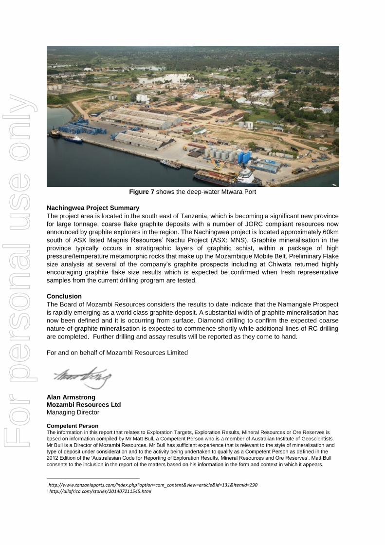
Figure 7 shows the deep-water Mtwara Port
Nachingwea Project Summary
The project area is located in the south east of Tanzania, which is becoming a significant new province
for large tonnage, coarse flake graphite deposits with a number of JORC compliant resources now
announced by graphite explorers in the region. The Nachingwea project is located approximately 60km
south of ASX listed Magnis Resources’ Nachu Project (ASX: MNS). Graphite mineralisation in the
province typically occurs in stratigraphic layers of graphitic schist, within a package of high
pressure/temperature metamorphic rocks that make up the Mozambique Mobile Belt. Preliminary Flake
size analysis at several of the company’s graphite prospects including at Chiwata returned highly
encouraging graphite flake size results which is expected be confirmed when fresh representative
samples from the current drilling program are tested.
Conclusion
The Board of Mozambi Resources considers the results to date indicate that the Namangale Prospect
is rapidly emerging as a world class graphite deposit. A substantial width of graphite mineralisation has
now been defined and it is occurring from surface. Diamond drilling to confirm the expected coarse
nature of graphite mineralisation is expected to commence shortly while additional lines of RC drilling
are completed. Further drilling and assay results will be reported as they come to hand.
For and on behalf of Mozambi Resources Limited Alan Armstrong Mozambi Resources Ltd Managing Director Competent Person The information in this report that relates to Exploration Targets, Exploration Results, Mineral Resources or Ore Reserves is
based on information compiled by Mr Matt Bull, a Competent Person who is a member of Australian Institute of Geoscientists.
Mr Bull is a Director of Mozambi Resources. Mr Bull has sufficient experience that is relevant to the style of mineralisation and
type of deposit under consideration and to the activity being undertaken to qualify as a Competent Person as defined in the
2012 Edition of the ‘Australasian Code for Reporting of Exploration Results, Mineral Resources and Ore Reserves’. Matt Bull
consents to the inclusion in the report of the matters based on his information in the form and context in which it appears.
i http://www.tanzaniaports.com/index.php?option=com_content&view=article&id=131&Itemid=290 ii http://allafrica.com/stories/201407211545.html
For
per
sona
l use
onl
y

JORC Code, 2012 Edition
Table 1
1
Section 1 Sampling Techniques and Data
Criteria JORC Code explanation Commentary
Sampling techniques
Nature and quality of sampling (eg cut channels, random chips, or specific specialised industry standard measurement tools appropriate to the minerals under investigation, such as down hole gamma sondes, or handheld XRF instruments, etc). These examples should not be taken as limiting the broad meaning of sampling.
Include reference to measures taken to ensure sample representivity and the appropriate calibration of any measurement tools or systems used.
Aspects of the determination of mineralisation that are Material to the Public Report.
In cases where ‘industry standard’ work has been done this would be relatively simple (eg ‘reverse circulation drilling was used to obtain 1 m samples from which 3 kg was pulverised to produce a 30 g charge for fire assay’). In other cases more explanation may be required, such as where there is coarse gold that has inherent sampling problems. Unusual commodities or mineralisation types (eg submarine nodules) may warrant disclosure of detailed information.
Sampling was carried out using RC Drilling using 1m samples. The full 1m interval was collected before being weighed then riffle spilt into samples weighing approximately 1.5kg.
All samples were geologically logged by a suitably qualified geologist and mineralized intercepts selected for assay at SGS in Johannesburg South Africa.
Drilling techniques
Drill type (eg core, reverse circulation, open-hole hammer, rotary air blast, auger, Bangka, sonic, etc) and details (eg core diameter, triple or standard tube, depth of diamond tails, face-sampling bit or other type, whether core is oriented and if so, by what method, etc).
RC Drilling is being conducted by JCIL Drill. Bit diameter was 4.5 inches face sampling bit.
Drill sample recovery
Method of recording and assessing core and chip sample recoveries and results assessed.
Measures taken to maximise sample recovery and ensure representative nature of the samples.
Whether a relationship exists between sample recovery and grade and whether sample bias may have occurred due to preferential loss/gain of fine/coarse material.
RC Recovery was recorded by weighing the recovered sample before splitting. Sample size was found to be consistent.
Logging Whether core and chip samples have been geologically and geotechnically logged to a level of detail to support appropriate Mineral Resource estimation, mining studies and metallurgical studies.
Whether logging is qualitative or quantitative in nature. Core (or costean, channel, etc) photography.
The total length and percentage of the relevant intersections logged.
Logging was carried out on each of the samples including lithology, amount of weathering by a suitably qualified geologist.
Data is initially conducted on paper logging sheets and is then transferred to excel logging sheets
Logging is semi-quantitative based on visual estimation.
For
per
sona
l use
onl
y

JORC Code, 2012 Edition
Table 1
2
Criteria JORC Code explanation Commentary
Sub-sampling techniques and sample preparation
If core, whether cut or sawn and whether quarter, half or all core taken.
If non-core, whether riffled, tube sampled, rotary split, etc and whether sampled wet or dry.
For all sample types, the nature, quality and appropriateness of the sample preparation technique.
Quality control procedures adopted for all sub-sampling stages to maximise representivity of samples.
Measures taken to ensure that the sampling is representative of the in situ material collected, including for instance results for field duplicate/second-half sampling.
Whether sample sizes are appropriate to the grain size of the material being sampled.
RC samples were taken at 1m intervals and then split into 1.5kg samples with a reference sample also taken.
All RC intervals were geologically logged and mineralized intervals selected for sampling at SGS in Johannesburg
Duplicate samples were taken at a ratio of 1 in 20 by retaining the final riffle split
QC measures also include blank samples and certified standards both of which are inserted at a ratio of 1:20. SGS also has its own internal QA/QC controls to ensure assay quality
All sampling was carefully supervised with ticket books containing pre-numbered tickets placed in the sample bag and double checked against the ticket stubs and field sample sheets to guard against mix ups
Quality of assay data and laboratory tests
The nature, quality and appropriateness of the assaying and laboratory procedures used and whether the technique is considered partial or total.
For geophysical tools, spectrometers, handheld XRF instruments, etc, the parameters used in determining the analysis including instrument make and model, reading times, calibrations factors applied and their derivation, etc.
Nature of quality control procedures adopted (eg standards, blanks, duplicates, external laboratory checks) and whether acceptable levels of accuracy (ie lack of bias) and precision have been established.
Blanks, duplicated and certified standards were inserted by the company at a ratio of 1:20.
The samples were sent to Mwanza in Tanzania for sample preparation before being were sent to South Africa for analysis for Total Graphitic Carbon (TGC) using the method GRAP_CSA05V LECO Total Carbon
The TGC analysis has been carried out by an industry accepted and recognized laboratory - SGS
TGC is the most appropriate method of Analysis for graphitic carbon.
SGS inserted its own standards and blanks.
Verification of sampling and assaying
The verification of significant intersections by either independent or alternative company personnel.
The use of twinned holes.
Documentation of primary data, data entry procedures, data verification, data storage (physical and electronic) protocols.
Discuss any adjustment to assay data.
Data was recorded by the sampling geologist and stored in the company’s master spreadsheet. The samples will be transported to the SGS Lab in Mwanza for initial preparation before SGS transported for Assay at their lab in Johannesburg, South Africa.
Location of data points
Accuracy and quality of surveys used to locate drill holes (collar and down-hole surveys), trenches, mine workings and other locations used in Mineral Resource estimation.
Specification of the grid system used.
A hand-held GPS was used to identify the position of all samples (xy horizontal error of 5 metres) and reported using ARC 1960 grid and UTM datum zone 37 south.
For
per
sona
l use
onl
y

JORC Code, 2012 Edition
Table 1
3
Criteria JORC Code explanation Commentary
Quality and adequacy of topographic control.
Data spacing and distribution
Data spacing for reporting of Exploration Results.
Whether the data spacing and distribution is sufficient to establish the degree of geological and grade continuity appropriate for the Mineral Resource and Ore Reserve estimation procedure(s) and classifications applied.
Whether sample compositing has been applied.
Drill spacing was carried out on a pattern of 400m by 160m currently only the first line is completed
Whether the data spacing and distribution is sufficient to calculate a Resource estimate is dependent on the grade continuity which will be determined after assays have been received
No compositing has been applied
Orientation of data in relation to geological structure
Whether the orientation of sampling achieves unbiased sampling of possible structures and the extent to which this is known, considering the deposit type.
If the relationship between the drilling orientation and the orientation of key mineralised structures is considered to have introduced a sampling bias, this should be assessed and reported if material.
Surface mapping and interpretation of ground EM data was used to orient the drill lines to get the most unbiased sampling of the mineralisation.
Drilling was planned to intersect the mineralization as close as possible to right angles. Results indicate the drill holes intersect the mineralisation at between 70-90 degrees.
Sample security
The measures taken to ensure sample security.
Transportation will occur at the completion of the program
Audits or reviews
The results of any audits or reviews of sampling techniques and data.
No audits or reviews have yet been under taken
For
per
sona
l use
onl
y

JORC Code, 2012 Edition
Table 1
4
Section 2 Reporting of Exploration Results
(Criteria listed in the preceding section also apply to this section.)
Criteria JORC Code explanation Commentary
Mineral tenement and land tenure status
Type, reference name/number, location and ownership including agreements or material issues with third parties such as joint ventures, partnerships, overriding royalties, native title interests, historical sites, wilderness or national park and environmental settings.
The security of the tenure held at the time of reporting along with any known impediments to obtaining a licence to operate in the area.
The prospecting license PL10718 which was granted on the 18th of July 2015 for a period of four years for the exploration of Graphite. The area covered by the prospecting licenses is 239.17km2. The License is situated in the Ruangwa District The License is located within the Lindi region of south-east Tanzania.
The PL is held by Nachi Resources Ltd, which in turn is 100% owned by Mozambi Resources. The surface area is administered by the Government as native title. The area is rural, with wilderness areas and subsistence farming occurring on the PL. The Tenements are subject to a 3% royalty on production to the previous owners of Nachi Resources, which can be reduced to 1.5% under an agreement with the previous owner. There are no other known issues that may affect the tenure.
Exploration done by other parties
Acknowledgment and appraisal of exploration by other parties.
There is no written record of previous exploration available for this area known to Mozambi Resources, The location of some graphite outcrops on the PL’s was known by the previous owners.
Geology Deposit type, geological setting and style of mineralisation.
The exploration targets occur in the basement rocks of the Mozambique belt system which principally comprise metamorphic rocks ranging from schist to gneisses including marbles, amphibolites, graphitic schist, mica and kyanite schist, acid gneisses, hornblende, biotite and garnet gneisses, quartzites, granulites, and pegmatite veins. Initial exploration has
focused on areas where there no overlying younger sedimentary sequences remaining.
Drill hole Information
A summary of all information material to the understanding of the exploration results including a tabulation of the following information for all Material drill holes:
A summary of this information including; eastings and northings of drill hole collars, RL, dip/azimuth, down hole length and hole length are provided in table 1.
For
per
sona
l use
onl
y

JORC Code, 2012 Edition
Table 1
5
Criteria JORC Code explanation Commentary
o easting and northing of the drill hole collar
o elevation or RL (Reduced Level – elevation above sea level in metres) of the drill hole collar
o dip and azimuth of the hole o down hole length and
interception depth o hole length.
If the exclusion of this information is justified on the basis that the information is not Material and this exclusion does not detract from the understanding of the report, the Competent Person should clearly explain why this is the case.
Data aggregation methods
In reporting Exploration Results, weighting averaging techniques, maximum and/or minimum grade truncations (eg cutting of high grades) and cut-off grades are usually Material and should be stated.
Where aggregate intercepts incorporate short lengths of high grade results and longer lengths of low grade results, the procedure used for such aggregation should be stated and some typical examples of such aggregations should be shown in detail.
The assumptions used for any reporting of metal equivalent values should be clearly stated.
No assays are reported in this Announcement
Relationship between mineralisation widths and intercept lengths
These relationships are particularly important in the reporting of Exploration Results.
If the geometry of the mineralisation with respect to the drill hole angle is known, its nature should be reported.
If it is not known and only the down hole lengths are reported, there should be a clear statement to this effect (eg ‘down hole length, true width not known’).
Drill lines are planned to be as close as possible to right angles to the mapped mineralization.
The width of mineralization ranges from close to 100% of the intercepts to approximately 85% of the interval as the mineralization is gently folded. Closer spaced drilling is required to find the exact relationship.
Diagrams Appropriate maps and sections (with scales) and tabulations of intercepts should be included for any significant discovery being reported These should include, but not be limited to a plan view of drill
A drill hole plan is provided in Figures 4 and 5 showing mineralised width
A cross Section is provided in Figure 6 showing the orientation of drilling relative to the interpreted geology.
For
per
sona
l use
onl
y

JORC Code, 2012 Edition
Table 1
6
Criteria JORC Code explanation Commentary
hole collar locations and appropriate sectional views.
Balanced reporting
Where comprehensive reporting of all Exploration Results is not practicable, representative reporting of both low and high grades and/or widths should be practiced to avoid misleading reporting of Exploration Results.
No assays are reported
Other substantive exploration data
Other exploration data, if meaningful and material, should be reported including (but not limited to): geological observations; geophysical survey results; geochemical survey results; bulk samples – size and method of treatment; metallurgical test results; bulk density, groundwater, geotechnical and rock characteristics; potential deleterious or contaminating substances.
Previous results from Namangale include. Ground EM survey results have also been reported previously. The announcement also includes a simplified geological map of the area.
Further work The nature and scale of planned further work (eg tests for lateral extensions or depth extensions or large-scale step-out drilling).
Diagrams clearly highlighting the areas of possible extensions, including the main geological interpretations and future drilling areas, provided this information is not commercially sensitive.
Exploration is now at the drilling stage with the aim of defining a JORC resource in the near future based in the area of the current line and at least 2 further planned lines to the north east and south west that will be drilled in the coming weeks.
For
per
sona
l use
onl
y