for prostream 5000 platform - harmonic inc
TRANSCRIPT

ProStream 5000 Platform
Platform Installation and Startup GuideVERSION 1.1
Rev B
Manual Part No. MAN-PS5K-PLAT-1.1

© 2010 Harmonic Inc. All rights reserved.
Disclaimer
Harmonic reserves the right to alter the equipment specifications and descriptions in this publication without prior notice. No part ofthis publication shall be deemed to be part of any contract or warranty unless specifically incorporated by reference into suchcontract or warranty. The information contained herein is merely descriptive in nature, and does not constitute a binding offer forsale of the product described herein. Harmonic assumes no responsibility or liability arising from the use of the products describedherein, except as expressly agreed to in writing by Harmonic. The use and purchase of this product do not convey a license underany patent rights, copyrights, trademark rights, or any intellectual property rights of Harmonic. Nothing hereunder constitutes arepresentation or warranty that using any products in the manner described herein will not infringe any patents of third parties.
Trademark Acknowledgments
Harmonic and all Harmonic product names are trademarks of Harmonic Inc. All other trademarks are the property of their respectiveowners.
Compliance and Approval
This equipment has been tested and found to comply with the limits for a Class A digital device, pursuant to Part 15, Subpart B of theFederal Communications Commission (FCC) rules.
These limits are designed to provide reasonable protection against harmful interference when the equipment is operated in acommercial environment.
This equipment generates, uses, and can radiate radio frequency energy. It may cause harmful interference to radio communicationsif it is not installed and used in accordance with the instructions in this manual. Operation of this equipment in a residential area islikely to cause harmful interference. If this occurs, the user will be required to correct the interference at his or her own expense.
This device complies with Part 15 of the FCC rules. Operation is subject to the following two conditions: (1) this device may notcause harmful interference, and (2) this device must accept any interference received, including interference that may causeundesired operation.
Connections between the Harmonic equipment and other equipment must be made in a manner that is consistent with maintainingcompliance with FCC radio frequency emission limits. Modifications to this equipment not expressly approved by Harmonic mayvoid the authority granted to the user by the FCC to operate this equipment.
WEEE/RoHS Compliance Policy
Harmonic Inc. intends to comply fully with the European Union’s Directive 2002/96/EC as amended by Directive 2003/108/EC, onWaste Electrical and Electronic Equipment, also known as “WEEE,” and Directive 2002/95/EC, as amended, on the Restriction ofuse of Hazardous Substances, also known as “RoHS.”
Harmonic will ensure that product which cannot be reused will be recycled in compliance with the WEEE Directive. To that end,users are advised that (1) Harmonic equipment is not to be discarded in household or office garbage, (2) Harmonic Inc. will pay thefreight for shipment of equipment to be disposed of if it is returned to Harmonic, (3) customers should call the normal RMAtelephone numbers to arrange for such shipment, and (4) for additional and updated information on this process customers mayconsult the Harmonic website: http://harmonicinc.com/ah_weee_recycle.cfm.
Harmonic will ensure that its products will be either reused or recycled in compliance with the WEEE Directive. For the latestinformation concerning Harmonic’s WEEE/RoHS Compliance Policy and its Recycling and Take-Back process, please visit our website.

© 2010 Harmonic Inc. All rights reserved.
Names and Contents of the Toxic and Hazardous Substances or Elements in theProducts if the Part is Present
This table shows those components where hazardous substances may be found in Harmonic products based on, among otherthings, material content information provided by third party suppliers. These components may or may not be part of the product.
The Environmental Protective Use Period for Harmonic products is 20 years unless displayed otherwise on the product. The EPUPperiod is valid only when the products are operated or stored as per the conditions specified in the product manual.
O:O: Indicates the content of the toxic and hazardous substances at the homogeneous material level of the parts is below the limitdefined in SJ/T11363 2006 standard.
X:X: Indicates that the content of the toxic and hazardous substances in at least one of the homogeneous materials of the parts isabove the limit defined in SJ/T11363 2006 standard.
(Part name) (Hazardous Substance)
(PB) (Hg) (Cd) (CrVI) (PBB) (PBDE)
(Printed Circuit Assemblies)
X O O O O O
(Mechanical Subassemblies)
X O O O O O
(Optical Subassemblies)
X O O O O O
(Power Supplies)X O O O O O
(Cables, harnesses)
X O O O O O
(Screens, Monitors)
X O O O O O
(Metal Parts)
O O O O O O
(Plastics, foams)O O O O O O
(Batteries)
X O O O O O

© 2010 Harmonic Inc. All rights reserved.
Standards and Agency Approval
The following tables list regulatory standards and agency approvals:
North America
Europe
Japan
Australia and New Zealand
Standards Agency Approval
EMI: FCC Part 15, Subpart B, ICES-003, Issue 2, Class A FCC
Safety: UL 60950, CSA 60950 cTUV-us Mark
Standards Agency Approval
EMI/EMC: EN55022, Class A, EN55024 CE
Safety: EN 60950 TUV-GS-Mark, CE
Standards Agency Approval
EMI: VCCI V-3 / 2000.04 VCCI
Standards Agency Approval
EMI: AS/NZS-3548: 1995 +A1: 1997 +A2: 1997 N/A

© 2010 Harmonic Inc. All rights reserved.
Documentation ConventionsThis manual uses some special symbols and fonts to call your attention to important information. Thefollowing symbols appear throughout this manual:
DANGER: The Danger symbol calls your attention to information that, if ignored, can cause physicalharm to you.
CAUTION: The Caution symbol calls your attention to information that, if ignored, can adversely affectthe performance of your Harmonic product, or that can make a procedure needlessly difficult.
LASER DANGER: The Laser symbol and the Danger alert call your attention to information about thelasers in this product that, if ignored, can cause physical harm to you.
NOTE: The Note symbol calls your attention to additional information that you will benefit fromheeding. It may be used to call attention to an especially important piece of information you need, or itmay provide additional information that applies in only some carefully delineated circumstances.
TIP: The Tip symbol calls your attention to parenthetical information that is not necessary for performinga given procedure, but which, if followed, might make the procedure or its subsequent steps easier,smoother, or more efficient.
In addition to these symbols, this manual uses the following text conventions:
■ Data Entry: indicates text you enter at the keyboard.
■ User Interface: indicates a button to click, a menu item to select, or a key or key sequenceto press.
■ Screen Output: shows console output or other text that is displayed to you on acomputer screen.
■ Bold: indicates the definition of a new term.
■ Italics: used for emphasis, cross-references, and hyperlinked cross-references in onlinedocuments.

Table of Contents
© 2010 Harmonic Inc. 6 ProStream 5000 Platform, Version 1.1, Rev B
Table of Contents
Chapter 1 Preface1.1 Installation Guide Organization . . . . . . . . . . . . . . . . . . . . . . . . . . . . . . . 91.2 Organization of This Manual . . . . . . . . . . . . . . . . . . . . . . . . . . . . . . . . . 9
Chapter 2 ProStream 5000 Overview2.1 ProStream 5000 Platform Hardware Overview . . . . . . . . . . . . . . . . . 11
2.1.1 ProStream 5000 Platform . . . . . . . . . . . . . . . . . . . . . . . . . . . . . . . . . . 11
Chapter 3 Planning a System3.1 Checklists for Planning . . . . . . . . . . . . . . . . . . . . . . . . . . . . . . . . . . . . . 133.2 Using the SMC Web Interface . . . . . . . . . . . . . . . . . . . . . . . . . . . . . . . 14
3.2.1 Connecting to the SMC . . . . . . . . . . . . . . . . . . . . . . . . . . . . . . . . . . . . 143.2.2 Navigating Through the SMC . . . . . . . . . . . . . . . . . . . . . . . . . . . . . . . 15
Chapter 4 Hardware Installation and Cabling4.1 Safety Precautions. . . . . . . . . . . . . . . . . . . . . . . . . . . . . . . . . . . . . . . . . 194.2 Physical Hardware Installation . . . . . . . . . . . . . . . . . . . . . . . . . . . . . . . 20
4.2.1 ProStream 5000 Platform Components . . . . . . . . . . . . . . . . . . . . . . 204.2.2 Unpacking and Initial Installation . . . . . . . . . . . . . . . . . . . . . . . . . . . . 214.2.3 Cabling the ProStream Platform 5000 Series . . . . . . . . . . . . . . . . . . 22
4.3 RSA Provisioning . . . . . . . . . . . . . . . . . . . . . . . . . . . . . . . . . . . . . . . . . . 234.4 SIM Provisioning (For ProStream 5000 Platform) . . . . . . . . . . . . . . . 23
Chapter 5 Platform Configuration5.1 Common Configuration . . . . . . . . . . . . . . . . . . . . . . . . . . . . . . . . . . . . 26
5.1.1 Setting the Static IP Address . . . . . . . . . . . . . . . . . . . . . . . . . . . . . . . . 265.1.2 To create a new routing table entry: . . . . . . . . . . . . . . . . . . . . . . . . . 275.1.3 Setting the Server Name . . . . . . . . . . . . . . . . . . . . . . . . . . . . . . . . . . . 285.1.4 Setting Date and Time . . . . . . . . . . . . . . . . . . . . . . . . . . . . . . . . . . . . . 295.1.5 Setting up Anti-virus Protection and Viewing Reports . . . . . . . . . . . 305.1.6 Procedures to change 1+1 virtual IP/application interface IP . . . . . 34
5.2 Individual Configuration . . . . . . . . . . . . . . . . . . . . . . . . . . . . . . . . . . . . 355.2.1 Network Interface Configuration . . . . . . . . . . . . . . . . . . . . . . . . . . . . 355.2.2 Host Name Resolution . . . . . . . . . . . . . . . . . . . . . . . . . . . . . . . . . . . . . 375.2.3 Address Resolution . . . . . . . . . . . . . . . . . . . . . . . . . . . . . . . . . . . . . . . 385.2.4 DNS Resolution . . . . . . . . . . . . . . . . . . . . . . . . . . . . . . . . . . . . . . . . . . 395.2.5 Network Common Setting . . . . . . . . . . . . . . . . . . . . . . . . . . . . . . . . . . 405.2.6 Network Load Balance . . . . . . . . . . . . . . . . . . . . . . . . . . . . . . . . . . . . 405.2.7 Network Load Balance Port Rules . . . . . . . . . . . . . . . . . . . . . . . . . . . 41
5.3 Firewall Setting . . . . . . . . . . . . . . . . . . . . . . . . . . . . . . . . . . . . . . . . . . . 435.4 Server Hardening (Lock-Down Protection) . . . . . . . . . . . . . . . . . . . . . 445.5 SNMP . . . . . . . . . . . . . . . . . . . . . . . . . . . . . . . . . . . . . . . . . . . . . . . . . . . 44
5.5.1 SNMP Settings . . . . . . . . . . . . . . . . . . . . . . . . . . . . . . . . . . . . . . . . . . . 44

Table of Contents
© 2010 Harmonic Inc. 7 ProStream 5000 Platform, Version 1.1, Rev B
5.5.2 Accepted communities . . . . . . . . . . . . . . . . . . . . . . . . . . . . . . . . . . . . 455.5.3 SNMP Traps setting . . . . . . . . . . . . . . . . . . . . . . . . . . . . . . . . . . . . . . . 465.5.4 Downloading MIB data . . . . . . . . . . . . . . . . . . . . . . . . . . . . . . . . . . . . 475.5.5 Certificate Management . . . . . . . . . . . . . . . . . . . . . . . . . . . . . . . . . . . 475.5.6 Image Upgrade . . . . . . . . . . . . . . . . . . . . . . . . . . . . . . . . . . . . . . . . . . 485.5.7 User Management . . . . . . . . . . . . . . . . . . . . . . . . . . . . . . . . . . . . . . . . 495.5.8 RAIDX Configuration . . . . . . . . . . . . . . . . . . . . . . . . . . . . . . . . . . . . . . 505.5.9 Managing the RAIDX Diagnostics Log . . . . . . . . . . . . . . . . . . . . . . . . 51
5.6 NIC Teaming Settings . . . . . . . . . . . . . . . . . . . . . . . . . . . . . . . . . . . . . . 525.6.1 Switch Fault Tolerance (SFT) . . . . . . . . . . . . . . . . . . . . . . . . . . . . . . . . 525.6.2 Teaming . . . . . . . . . . . . . . . . . . . . . . . . . . . . . . . . . . . . . . . . . . . . . . . . 525.6.3 Switch Requirements . . . . . . . . . . . . . . . . . . . . . . . . . . . . . . . . . . . . . . 52
5.7 Setting up 1+1 Redundancy . . . . . . . . . . . . . . . . . . . . . . . . . . . . . . . . 535.8 Setting Up 1+1 on SMC . . . . . . . . . . . . . . . . . . . . . . . . . . . . . . . . . . . . 57
5.8.1 Verification . . . . . . . . . . . . . . . . . . . . . . . . . . . . . . . . . . . . . . . . . . . . . . 595.9 NAS Configuration . . . . . . . . . . . . . . . . . . . . . . . . . . . . . . . . . . . . . . . . 59
5.9.1 Creating NAS mounting . . . . . . . . . . . . . . . . . . . . . . . . . . . . . . . . . . . . 595.9.2 Modifying a NAS Mounting . . . . . . . . . . . . . . . . . . . . . . . . . . . . . . . . . 605.9.3 Deleting a NAS Mounting . . . . . . . . . . . . . . . . . . . . . . . . . . . . . . . . . . 61
5.10 Single Sign On (SSO) Configuration. . . . . . . . . . . . . . . . . . . . . . . . . . . 615.10.1 Enabling SSO . . . . . . . . . . . . . . . . . . . . . . . . . . . . . . . . . . . . . . . . . . . . 615.10.2 Disabling SSO . . . . . . . . . . . . . . . . . . . . . . . . . . . . . . . . . . . . . . . . . . . . 61
Chapter 6 Platform Operation6.1 Shutting Down and Rebooting the System . . . . . . . . . . . . . . . . . . . . . 626.2 Starting, Stopping, and Restarting Services . . . . . . . . . . . . . . . . . . . . 636.3 Service Start and Stop. . . . . . . . . . . . . . . . . . . . . . . . . . . . . . . . . . . . . . 64
Chapter 7 Diagnostic Logs7.1 Anti-Virus Logs and Reports . . . . . . . . . . . . . . . . . . . . . . . . . . . . . . . . 657.2 Event Logs . . . . . . . . . . . . . . . . . . . . . . . . . . . . . . . . . . . . . . . . . . . . . . . 657.3 System Message Logger . . . . . . . . . . . . . . . . . . . . . . . . . . . . . . . . . . . 67
7.3.1 Category . . . . . . . . . . . . . . . . . . . . . . . . . . . . . . . . . . . . . . . . . . . . . . . . 687.3.2 Destination Settings . . . . . . . . . . . . . . . . . . . . . . . . . . . . . . . . . . . . . . . 697.3.3 Mapping . . . . . . . . . . . . . . . . . . . . . . . . . . . . . . . . . . . . . . . . . . . . . . . . 737.3.4 Activating, Adding, or Removing a Log . . . . . . . . . . . . . . . . . . . . . . . 75
7.4 Audit Trail Log . . . . . . . . . . . . . . . . . . . . . . . . . . . . . . . . . . . . . . . . . . . . 76
Chapter 8 Maintenance and Troubleshooting8.1 Viewing Status and System Information . . . . . . . . . . . . . . . . . . . . . . . 77
8.1.1 Hardware Identification . . . . . . . . . . . . . . . . . . . . . . . . . . . . . . . . . . . . 788.1.2 Software Information . . . . . . . . . . . . . . . . . . . . . . . . . . . . . . . . . . . . . . 798.1.3 Diagnostics . . . . . . . . . . . . . . . . . . . . . . . . . . . . . . . . . . . . . . . . . . . . . . 808.1.4 Licensing Information . . . . . . . . . . . . . . . . . . . . . . . . . . . . . . . . . . . . . 818.1.5 Viewing Disk Usage . . . . . . . . . . . . . . . . . . . . . . . . . . . . . . . . . . . . . . . 828.1.6 Viewing Physical Disk Information . . . . . . . . . . . . . . . . . . . . . . . . . . . 83
8.2 Viewing Anti-Virus Reports . . . . . . . . . . . . . . . . . . . . . . . . . . . . . . . . . 84

Table of Contents
© 2010 Harmonic Inc. 8 ProStream 5000 Platform, Version 1.1, Rev B
8.3 Maintenance . . . . . . . . . . . . . . . . . . . . . . . . . . . . . . . . . . . . . . . . . . . . . 848.3.1 Managing RAIDX Arrays . . . . . . . . . . . . . . . . . . . . . . . . . . . . . . . . . . . 848.3.2 Server Dump Files . . . . . . . . . . . . . . . . . . . . . . . . . . . . . . . . . . . . . . . . 888.3.3 Backup and Restore Configuration . . . . . . . . . . . . . . . . . . . . . . . . . . . 898.3.4 Restore Profiles . . . . . . . . . . . . . . . . . . . . . . . . . . . . . . . . . . . . . . . . . . 908.3.5 Replace a Hard Disk Drive (HDD) . . . . . . . . . . . . . . . . . . . . . . . . . . . 908.3.6 Light Path Diagnostics . . . . . . . . . . . . . . . . . . . . . . . . . . . . . . . . . . . . . 908.3.7 Replace Power Supply . . . . . . . . . . . . . . . . . . . . . . . . . . . . . . . . . . . . . 918.3.8 POST Beep Codes . . . . . . . . . . . . . . . . . . . . . . . . . . . . . . . . . . . . . . . . 928.3.9 Management Events . . . . . . . . . . . . . . . . . . . . . . . . . . . . . . . . . . . . . . 928.3.10 1+1 Upgrade Procedures . . . . . . . . . . . . . . . . . . . . . . . . . . . . . . . . . . 93
8.4 Ping Utility . . . . . . . . . . . . . . . . . . . . . . . . . . . . . . . . . . . . . . . . . . . . . . . 968.5 Contacting Harmonic Support . . . . . . . . . . . . . . . . . . . . . . . . . . . . . . . 98
Glossary 99

© 2010 Harmonic Inc. 9 ProStream 5000 Platform, Version 1.1, Rev B
Chapter 1Preface
This guide describes how to install and configure the pre-integrated Harmonic solution —Harmonic hardware platforms that are optimized for ProStream 5000 Platform software. It isthe first part in the three-part installation process for a ProStream 5000 Platform system.
The following diagram illustrates the overall process for proper installation of a ProStream5000 Platform system. Steps A through C are covered in this guide.
Figure 1-1: ProStream 5000 Installation Flowchart
1.1 Installation Guide OrganizationThe installation procedures for a complete system are covered in three installation guides:
■ Platform Installation and Startup Guide (this guide) — describes the installation of theunderlying ProStream 5000 Platform upon which all applications run.
■ Application Configuration Guide — describes configuration and use of specific on-demand applications, including VOD. These applications run on top of the ProStream5000 Platform.
■ Ecosystem Configuration Guide — describes configuration and use of on-demandapplications, including VOD, in specific ecosystems.
You need to follow the procedures in all three guides to ensure the installation of an entiresystem application. Please refer to the configuration guides to complete the installation of theentire system.
1.2 Organization of This ManualThis installation guide is organized as follows:
■ Chapter 1, Preface (this chapter), describes how to use the three installation guides andoutlines the guide’s organization.
■ Chapter 2, ProStream 5000 Overview, describes the ProStream 5000 system andprovides product specifications.
■ Chapter 3, Planning a System, provides an overview of ProStream 5000 Platform serverroles within an application, and describes using the SMC.

Chapter 1 Preface Organization of This Manual
© 2010 Harmonic Inc. 10 ProStream 5000 Platform, Version 1.1, Rev B
■ Chapter 4, Hardware Installation and Cabling, describes the ProStream 5000 Platformhardware installation, cabling, and RSA provisioning.
■ Chapter 5, Platform Configuration, describes configuration of the ProStream 5000Platform.
■ Chapter 6, Platform Operation, describes basic system startup and shutdown operations.
■ Chapter 7, Diagnostic Logs, describes event logs and the System Message Logger.
■ Chapter 8, Maintenance and Troubleshooting, covers maintenance and monitoring tasks,and Harmonic Support contact information.
■ Glossary provides definitions for the most common abbreviations and acronyms used inthis document.

© 2010 Harmonic Inc. 11 ProStream 5000 Platform, Version 1.1, Rev B
Chapter 2ProStream 5000 Overview
This chapter contains an overview of the ProStream 5000 Platform hardware.
2.1 ProStream 5000 Platform Hardware OverviewHarmonic offers ProStream 5000 Platform models with different form factors. Each chassis isoptimized for rack mounting, making it possible to deploy a very compact solution. TheProStream 5000 Platform models are:
■ The ProStream 5000. (See 2.1.1 ProStream 5000 Platform on page 11.)
2.1.1 ProStream 5000 PlatformThe Prostream 5000 front panel is shown in Figure 2-1 on page 11, and the back panel isshown in Figure 2-2 on page 11.
You can see these components on the front panel:
■ A disk enclosure for up to four drives. Each slot has two LEDs that show the power andactivity status of each drive.
■ Two of the drives are mounted with CF cards. The other two are mounted with SSDs.
Figure 2-1: Front panel of the ProStream 5000
Figure 2-2: Back panel of the ProStream 5000
You can see these components on the back panel of the ProStream 5000:
■ Power supply
■ Network interfaces

Chapter 2 ProStream 5000 Overview ProStream 5000 Platform Hardware Overview
© 2010 Harmonic Inc. 12 ProStream 5000 Platform, Version 1.1, Rev B
■ USB ports
■ COM ports
■ VGA ports
2.1.1.1 ProStream 5000 G2
Figure 2-3: ProStream 5000 G2 - Front Panel
Figure 2-4: ProStream 5000 G2 - Back Panel

© 2010 Harmonic Inc. 13 ProStream 5000 Platform, Version 1.1, Rev B
Chapter 3Planning a System
This chapter provides guidelines for planning a ProStream 5000 Platform system, and gives adescription of the System Management Console (SMC).
It contains the following sections:
■ Planning your ProStream 5000 Setup and Configuration
■ Using the SMC Web Interface
3.1 Checklists for PlanningThe following checklists provide a general guideline for the settings you should define orconfigure:
ProStream 5000 Platform Checklist■ RAIDX build / format
■ Interface role assignment (streaming / multicast / application)
■ IP address assignment
■ Routing table configuration
■ Host name
■ Host table
■ Time zone and time server
■ Initialize server settings
Cluster Controller Checklist■ Interface role assignment (streaming / multicast / application)
■ IP address assignment
■ Routing table configuration
■ Host name
■ Host table
■ Time zone and time server
■ Ensure that the modules are started (start services) — modules to be started depend onthe roles defined for each server in the application
■ Content ingest trick speed configuration
■ Content replication configuration
■ Asset management (FTP, Ingest Gateway)
■ Middleware
■ STB / RTSP
■ Catcher
■ DRM encryptor
For information about configuring individual modules, see the Platform ApplicationConfiguration Guide and the Platform Ecosystem Configuration Guide.

Chapter 3 Planning a System Using the SMC Web Interface
© 2010 Harmonic Inc. 14 ProStream 5000 Platform, Version 1.1, Rev B
This guide assumes that you have evaluated your application needs, and are ready to beginputting the system together.
3.2 Using the SMC Web InterfaceThe System Management Console (SMC) is the main interface for configuring, operating, andmaintaining the server. SMC is equipped with both an efficient console-based interface and auser-friendly web-based interface.
This section describes:
■ Connecting to the SMC
■ Navigating Through the SMC
3.2.1 Connecting to the SMCIf the ProStream 5000 Platform server has an IP address, you can access the server over thenetwork to view the web-based SMC. Otherwise, you can connect a monitor, mouse, andkeyboard to the server to view SMC locally.
For information about installing a ProStream 5000 Platform server and assigning it an IPaddress, or information about connecting locally, see 5.1 Common Configuration onpage 26.
The web-based SMC displays a GUI that you can use to remotely configure a ProStream5000 Platform server. When you first open a web browser to the server, the SMC opens tothe Status screen.
Figure 3-2 on page 15 shows the information that you see from most cluster nodes and thespecial status screen that you see from the Cluster Controller.
Figure 3-1: SMC’s status screen

Chapter 3 Planning a System Using the SMC Web Interface
© 2010 Harmonic Inc. 15 ProStream 5000 Platform, Version 1.1, Rev B
Figure 3-2: Cluster controller’s status screen
The left pane displays a snapshot of the server’s status, or “health.” Most SMC nodes showyou:
■ The server’s name and the percent of CPU currently being used on it.
■ Number of VOD streams active.
■ Total broadcast channels, and total that are currently active.
■ Status of RAIDX and of LSCP, RTSP, and RSVP protocols (healthy/enabled/disabled).
■ Refresh: You can click to start a new refresh. You can reset the auto-refresh time. Thecurrent auto-refresh time is shown, and the time of last refresh.
The main pane opens to the Status tab by default:
■ Status — initial SMC screen with overall status information about the node.
■ The server, name and percent of CPU.
■ System and RAID free space, and RAID status.
■ Streaming status, number of VOD sessions current, and number of broadcast channelson this server.
■ Status of protocol interfaces on this server (enabled/disabled).
■ What scheduling capabilities are enabled on the server:
❑ Whether broadcast channeling can be done through the server.
❑ Whether the server can provide XML interface for ingest scheduling.
3.2.2 Navigating Through the SMCThis section assume that you have started the SMC and have the initial Status screen loaded.Navigate through the options by clicking a tab name to open it, and making the selectionsand entries as needed.
If a tab has sub-topics, they are listed.
[Folder] indicates there are more subtopics, [Table] indicates there are no subtopics to click.

Chapter 3 Planning a System Using the SMC Web Interface
© 2010 Harmonic Inc. 16 ProStream 5000 Platform, Version 1.1, Rev B
For example, the Configuration tab has several subtopic folders, as shown in Figure 3-3 onpage 16.
Figure 3-3: Main pane with tabs, topics, and subtopics
The tabs are explained below:
■ Status
■ Configuration. Click a subhead to configure selections.
■ Service. Start, stop, and restart services.
■ Platform. Click a subhead to configure selections.
■ Operation. Manage streaming parameters (not available on Cluster Controller servers).
■ Diagnostics. Access logs and diagnostic information.
■ Software information. View software version verification.
■ Backup/Restore. Back up and restore system configuration files.
3.2.2.1 Path
The path display shows your position in each tab, and allows you to navigate by clicking thelevel you wish to move to. Figure 3-4 shows the path for the DRM Profile settings screen.
Figure 3-4: .Path display in SMC

Chapter 3 Planning a System Using the SMC Web Interface
© 2010 Harmonic Inc. 17 ProStream 5000 Platform, Version 1.1, Rev B
3.2.2.2 Buttons
Move to the screen level you want by clicking the menu item or button choice for that screen.Figure 3-5 shows the buttons for DRM Profile and Transcoder Profile.
Figure 3-5: Select button in SMC
To back up one level on each tab, click the file folder icon located below the path display,if one is available. To back up to any level in the path, click the name of the level. For example,in Figure 3-5, if you want to return to Configuration, simply click Configuration in the path.
3.2.2.3 Select
When an entry field shows a Select button, you can type in your entry or click Select to displaya list of options to choose from (see Figure 3-5). The list of options will display in a newbrowser window, and when you click an option, the entry field will be populated with yourselection automatically.
3.2.2.4 Tasks
You can create, edit, and delete configuration settings. A Task menu displays on the right sideof the screen to offer you the available tasks for the current configuration.Figure 3-6 shows the Task menu for the Routing Table option.
Figure 3-6: Task menu in SMC
3.2.2.5 Data Entry
Entry fields marked with an * (asterisk) are required entries.
NOTE: User-defined names may not contain the following characters: \/”[]:|<>+=;,?*@. Theymay not consist entirely of any combination of periods (.) or spaces ( ).

Chapter 3 Planning a System Using the SMC Web Interface
© 2010 Harmonic Inc. 18 ProStream 5000 Platform, Version 1.1, Rev B
In some settings where multiple entries are possible, the Add icon ( ) displays to the rightof the field to facilitate adding entries to the setting. The icon appears only when the mousepointer is positioned on that entry field. See Figure 3-7 for an example of an entry field withthe Add icon and its attendant tool buttons.
Figure 3-7: Add icon in SMC
3.2.2.6 Apply
On most screens, when you are finished making entries and selections, click the Apply buttonto make the settings active (see Figure 3-8).
Figure 3-8: Apply settings button

© 2010 Harmonic Inc. 19 ProStream 5000 Platform, Version 1.1, Rev B
Chapter 4Hardware Installation and Cabling
This chapter describes how to install the ProStream 5000 Platform servers on a network, andhow to prepare them to be configured for their respective roles.
This chapter has information about:
■ Safety Precautions
■ Physical Hardware Installation
■ RSA Provisioning
■ SIM Provisioning (For ProStream 5000 Platform)
4.1 Safety PrecautionsTo protect your ProStream 5000 Platform equipment from potential damage and to ensureyour own personal safety, follow these safety guidelines:
■ Never operate ProStream 5000 Platform with the cover removed.
■ Before installing ProStream 5000 Platform, unplug the system to prevent electric orsystem board damage.
■ To help prevent electric shock, plug the power cable into properly grounded sources. Useonly properly grounded extension cords and adaptors, if they are needed.
■ Make sure that nothing is lying on the ProStream 5000 Platform power cable.
■ Be sure that the cables are located where they will not be stepped on or tripped over.
■ Do not spill food or liquids on your ProStream 5000 Platform unit.
■ Do not push any objects into the free slots of your ProStream 5000 Platform unit. Doingso will damage your ProStream 5000 Platform unit and can cause fire or electrical shock,and short out interior components.
■ Keep your ProStream 5000 Platform unit away from heat sources and radiators.
■ Do not block cooling vents.
■ Do not place your ProStream 5000 Platform unit in a closed-in wall unit.
■ When you disconnect a cable, pull on its connector or on its strain relief loop, not on thecable itself. Some cables have a connector with locking tabs; if you are disconnecting thistype of cable, press in on the locking tabs before disconnecting the cable. As you pullconnectors apart, keep them evenly aligned to avoid bending any connector pins.
■ When you connect a cable, make sure that both connectors are correctly oriented andaligned before connecting to avoid bending connector pins.

Chapter 4 Hardware Installation and Cabling Physical Hardware Installation
© 2010 Harmonic Inc. 20 ProStream 5000 Platform, Version 1.1, Rev B
4.2 Physical Hardware InstallationThe ProStream Platform 5000 series is based on the IBM System x3650. For detailedinstructions on setting up an IBM server, see Chapter 2 of the IBM System x3650 InstallationGuide.
This section describes the following:
■ ProStream 5000 Platform Components
■ Unpacking and Initial Installation
■ Cabling the ProStream Platform 5000 Series
4.2.1 ProStream 5000 Platform ComponentsThe basic ProStream 5000 Platform package comes with the following components:
Table 4-1: ProStream 5000 Platform Components
Item Description
Documentation Platform Installationand Startup Guide
This guide explains how to install, configure,and operate ProStream 5000 Platformservers on a ProStream 5000 Platformsystem.
Hardwarecomponents
Chassis (x1) ■ Cooling fan■ Locking security cover■ 19" rack-mounting kit and rails■ HDD enclosure■ Flash memory adapter■ Power cord
Network InterfaceModule (xN)
■ Gigabit Ethernet (UTP)■ Dual Gigabit Ethernet (UTP)■ Quad Gigabit Ethernet (UTP)■ Hex Gigabit Ethernet (UTP)
Hard disk drive (xN) ■ HDD (SAS) 72 GB 15K■ HDD (SAS) 147 GB 15K■ HDD (SAS) 300 GB 15K
Dongle (depending onconfiguration)
USB license dongle
Softwarecomponents
ProStream 5000Platform softwarepackaged in CompactFlash Card (x1)
ProStream 5000 Platform software Version1.1
Software license (x1) Base O/S license and client license pack

Chapter 4 Hardware Installation and Cabling Physical Hardware Installation
© 2010 Harmonic Inc. 21 ProStream 5000 Platform, Version 1.1, Rev B
4.2.2 Unpacking and Initial Installation1. Choose a suitable location for ProStream 5000 Platform.
2. Unpack ProStream 5000 Platform and its components carefully, and make sure that youhave all the required components available.
3. If required, rack-mount the ProStream 5000 Platform by attaching the rack-mounting kitto the chassis with screws. Fasten the rail onto the 19-inch rack. In this way, ProStream5000 Platform can be securely mounted.
4. Install the hard disk drives into the HDD enclosure properly.
❑ Be sure to take appropriate ESD precautions and work in a properly groundedenvironment.
❑ Swing open the main latch on the hard disk drive.
❑ Carefully insert the new drive into the drive slot.
❑ Ensure that the latch is locked to the HDD enclosure.
5. If AC power is used, make sure that the power supply is switched to the correct voltage(110/220V). The power cord connects to the power connector on ProStream 5000Platform’s rear panel.
NOTE: In case a redundant power supply is used, two power cords are needed instead of one. Ensure thateach cord is plugged into a separate power circuit.
6. Insert the flash card into the flash drive of the ProStream 5000 Platform server.
❑ Ensure that the server is turned off.
❑ Locate the flash memory card slot on the front of the server.
❑ Insert the compact flash card. Push the card all the way down until it stays firmly inplace. It is properly seated when the card eject button pops up.
7. Make sure that all network connections are connected properly. Ensure that the GigabitEthernet ports and the Management/Logging Fast Ethernet ports are connected to theappropriate devices.
8. Insert the appropriate license dongle.

Chapter 4 Hardware Installation and Cabling Physical Hardware Installation
© 2010 Harmonic Inc. 22 ProStream 5000 Platform, Version 1.1, Rev B
4.2.3 Cabling the ProStream Platform 5000 SeriesConnecting cables to the ProStream 5000 Platform is straightforward. Refer to the back panelof the corresponding model for placement of the ports.
4.2.3.1 Connecting the ProStream 5000 Platform server to storage expansion units
Use the SAS cable that comes with the storage expansion unit to connect the storageexpansion unit to the ProStream 5000 Platform server in the following sequence:
Figure 4-1 shows the position of the ports on the expansion units.
Figure 4-1: Connecting ProStream 5000 Platform storage expansion units
Table 4-2: Connecting to Storage Expansion Units
Connect from: Connect to:
First expansion unit SAS “In” port ProStream 5000 Platform server SAS 1port
Second expansion unit SAS “In” port ProStream 5000 Platform server SAS 2port
Third expansion unit SAS “In” port First expansion unit SAS “Out” port
Fourth expansion unit SAS “In” port Second expansion unit SAS “Out” port

Chapter 4 Hardware Installation and Cabling RSA Provisioning
© 2010 Harmonic Inc. 23 ProStream 5000 Platform, Version 1.1, Rev B
4.3 RSA ProvisioningRSA (Remote Supervisor Adapter) is an IBM tool that enables:
■ Around-the-clock remote access and system management of the server
■ Remote management, independent of the status of the managed server
■ Remote control of hardware and operating systems
■ Web-based management with standard web browsers
The RSA card is installed with the following default settings:
NOTE: All Harmonic ProStream 5000 Platform units have been set to the default values in Table 4-3. Forsecurity, Harmonic recommends that you change the default password during your initial session.
To provision the RSA you must give the card a unique IP address, so that you can access itremotely. You should perform this step as you deploy each ProStream 5000 Platform serverto the network, and before you deploy another server. For detailed instructions on how tochange the IP address, consult the IBM Remote Supervisory Adapter User Guide.
To access the RSA remotely:
1. Open a web browser and enter the IP address or host name of the RSA to which youwant to connect. If you have not changed the default settings, use the values inTable 4-3.
2. The Enter Network Password window opens. Enter the user name and password. The RSAwelcome page opens in your browser.
3. Select a time-out value from the drop-down list. RSA logs you off the web interface if thebrowser is inactive for the selected number of minutes.
4. Click Continue to start the session. The browser opens the System Status page, whichgives you a quick view of the server status and the server “health” summary. You can nowchange the IP address of the RSA interface. Correct RSA setup for all the ProStream 5000Platform servers in your system facilitates troubleshooting and technical support.
4.4 SIM Provisioning (For ProStream 5000 Platform)Supermicro Intelligent Management (SIM) module implements IPMI 2.0 technology to provideremote access, monitoring and administration for Supermicro server platforms.
With SIM, server administrators can view a server's hardware status remotely, receive analarm automatically if a failure occurs, and power cycle a system that is non-responsive.
The SIM is installed with the default settings in Table 4-4: Default Setting.
Table 4-3: ProStream 5000 Platform Default RSA Settings
Setting Default
IP 10.10.10.10
Port 80
Web access user name superuser
Web access password smc!@#321

Chapter 4 Hardware Installation and Cabling SIM Provisioning (For ProStream 5000 Platform)
© 2010 Harmonic Inc. 24 ProStream 5000 Platform, Version 1.1, Rev B
NOTE: All Harmonic ProStream 5000 units have been set to the default values in Table 4-4. For security,Harmonic recommends that you change the default password during your initial session.
To provision the SIM you must give the card a unique IP address, so that you can access itremotely. You should perform this step as you deploy each ProStream Platform server to thenetwork, and before you deploy another server. For detailed instructions on how to changethe IP address, consult the SuperMicro AOC-SIMSO+ User Guide.
To access the SIM remotely:
1. Open a web browser and enter the IP address or host name of the SIM to which you wantto connect. If you have not changed the default settings, use the values in Table 4-4.
2. The Enter Network Password window opens. Enter the user name and password. TheIMM welcome page opens in your browser.
3. Click Continue to start the session. To get a quick view of the server status and the server“health” summary, select the System Healths > Monitor Sensors for ProStream 5000 G1and select the System Healths > Sensor Readings for ProStream 5000 G2.
You can now change the IP address of the SIM interface. To facilitate troubleshooting andtechnical support, ensure that all of the ProStream Platform servers in your system havethe correct SIM setup.
Table 4-4: Default Setting
Setting Default
IP 192.168.70.131 (for primary serverboard)192.168.70.132 (for secondary serverboard)
Port 80
Web access user name superuser
Web access password smc!@#321

© 2010 Harmonic Inc. 25 ProStream 5000 Platform, Version 1.1, Rev B
Chapter 5Platform Configuration
This chapter first describes the common initial configuration necessary to place the server onthe network and run the SMC GUI. It then describes the individual settings that varydepending on the specific role of the server.
This chapter describes how to make the following settings:
■ Common Configuration
■ Individual Configuration
For the configuration of specific applications and ecosystems, refer to the ApplicationConfiguration Guide, and to the Ecosystem Configuration Guide relevant to your installation.
The ProStream 5000 Platform system can be configured in a variety of ways, depending onthe network environment and your video service needs. There are two main types ofplatforms: ProStream 5000 Platform and Cluster Controller. Both share a number of commonsettings, as seen in Table 5-1.
Table 5-1: Platform Settings
Setting ProStream5000 Platform
ClusterControllerPlatform
RAIDX build / format Yes
Interface role assignment (streaming /multicast / application)
Yes Yes
IP address assignment Yes Yes
Routing table configuration Yes Yes
Host name Yes Yes
Host table Yes Yes
Time zone and time server Yes Yes
Initialize server settings Yes Yes

Chapter 5 Platform Configuration Common Configuration
© 2010 Harmonic Inc. 26 ProStream 5000 Platform, Version 1.1, Rev B
5.1 Common ConfigurationProStream 5000 Platform is pre-configured to use the Dynamic Host Configuration Protocol(DHCP) to get an IP address and its basic TCP/IP settings.
If your network uses DHCP, the ProStream 5000 Platform obtains its TCP/IP settingsautomatically when you connect it to the network.
If DHCP is not enabled, then you must connect a pointing device (such as mouse ortrackball), a keyboard, and a monitor to the server. After connecting these, you can log in tothe System Management Console (SMC) directly and configure the basic TCP/IP informationneeded to get started and use SMC remotely. See 3.2 Using the SMC Web Interface onpage 14 for instructions on using SMC.
After the initial configuration is completed, you can access SMC remotely via HTTP. To do so,open a browser on any machine that can connect to the ProStream 5000 Platform system,and type in the URL for the ProStream 5000 Platform server, using either the IP address orthe host name/domain name format.
This section describes the following:
■ Setting the Static IP Address
■ Setting the static IP address Routing Table Adjustments
■ Setting the Server Name
■ Setting Date and Time
NOTE: These changes take effect after you reboot the ProStream 5000 Platform server. You must rebootbefore you can use SMC remotely, since it is a web-based console and relies on the IP address or hostname to connect.
5.1.1 Setting the Static IP AddressTo set the static IP address:
1. Navigate to /Platform/Network/Interfaces.
Check the appropriate Local Area Connection link that corresponds to the managementnetwork interface, and click Open in the Task list on the far right of the screen.
Figure 5-1: Open a network interface
2. Click Set static IP.

Chapter 5 Platform Configuration Common Configuration
© 2010 Harmonic Inc. 27 ProStream 5000 Platform, Version 1.1, Rev B
3. Fill in the IP address and subnet mask that have been assigned to the ProStream 5000Platform server using standard dotted-four notation. Enter the Default Gateway address,if needed.
4. Click Apply.Figure 5-2: Setting the static IP address Routing Table Adjustments
When you install a ProStream 5000 Platform server, the system automatically sets up therouting table. However, you might need to make adjustments to the routing table for yournetwork. You can open existing routing tables entries only for viewing and deleting, not forediting.
5.1.2 To create a new routing table entry:1. Navigate to /Platform/Network/Routing Table.
Figure 5-3: Platform / Network / Routing Table

Chapter 5 Platform Configuration Common Configuration
© 2010 Harmonic Inc. 28 ProStream 5000 Platform, Version 1.1, Rev B
2. Click New to create a new entry.Figure 5-4: Routing Table configuration
Enter Network destination.
Enter Netmask.
Enter Gateway.
Enter Metric values (1 to 9999).
Enter Interface. (Optionally) You usually provide an IP address, but you can enter aninterface ID number. If you leave this blank, the ProStream 5000 Platform system will tryto discover the most suitable interface to use.
Select a Type (Active /Persistent). This is an optional field:
❑ Active: The routing table entry is static and remains valid until reboot.
❑ Persistent: The routing table entry is persistent and remains valid even after reboot.
3. Click Apply.
NOTE: The network route cannot take effect unless at least one of the network interfaces can reach thegateway.
5.1.3 Setting the Server Name1. Navigate to /Platform/General.
2. Enter new Host name.
3. Click Apply.

Chapter 5 Platform Configuration Common Configuration
© 2010 Harmonic Inc. 29 ProStream 5000 Platform, Version 1.1, Rev B
Figure 5-5: Set server name
5.1.4 Setting Date and TimeAn accurate system date and time are crucial to providing most video services, especially fortime-shifted broadcast services. The simplest way to keep accurate time on your network is touse one of the many Network Time Protocol (NTP) servers available in your network.
NOTE: If an NTP time server is not available, configure the Cluster Controller server as “Operate as NTPServer”. Times in the Cluster Controller and the ProStream Nodes must be synchronized.
To set date and time:
1. Navigate to /Platform/Operating System.Figure 5-6: Set date and time
Select the appropriate Time Zone Region.

Chapter 5 Platform Configuration Common Configuration
© 2010 Harmonic Inc. 30 ProStream 5000 Platform, Version 1.1, Rev B
Enter Local date and time.
2. Click Apply.
5.1.5 Setting up Anti-virus Protection and Viewing ReportsTo protect your platform from viruses, spyware, and malicious intrusion, ProStream includesanti-virus software in its installation. It has a real-time scan engine to ensure that the server isprotected 24 hours a day.
The definition files are kept up to date. By default, this is done offline, with a patch. You canchoose to do it online.
Real-time scans protect the server by scanning files when they are accessed or modified. Thisincludes opening, running, copying, moving, renaming, and creating files. The scan profile istuned to minimize the impact on both streaming and ingest performance.
In addition, more complete scans supplement the real-time scans. These scans are moreextensive, but require a little more CPU load. You can set the weekly schedule for times whenyour CPU usage is lowest.
When a risk is detected, the software will attempt to clean the risk. It will also send aProStream alarm, an SNMP trap, and an NMX alarm. You can review logs and reports fromthe management console in path: /Operation / Anti Virus / Log.
To set up anti-virus software, and to view reports, navigate to /Operation / Anti Virus /.
Figure 5-7: Operation / Anti Virus
Complete the Version, Schedule Scan (optional), and Live Update sections to set up theanti-virus software. Use the Log folder tab to view the anti-virus reports.

Chapter 5 Platform Configuration Common Configuration
© 2010 Harmonic Inc. 31 ProStream 5000 Platform, Version 1.1, Rev B
5.1.5.1 View Anti-virus Version Information
To see information about the anti-virus program installed on your server, navigate toOperation / Anti Virus / Version.
5.1.5.2 Schedule the Anti-virus Scan
Now schedule the scans.
1. Navigate to /Operation / Anti Virus / Schedule Scan.
Figure 5-8: Schedule anti-virus scan operation
Scans are always scheduled weekly. Enter the Day of the week, and Time (using a 24-hour clock) that you want the weekly scan to begin.
2. Click Apply.
5.1.5.3 Enable Anti-virus Live Updates
To enable or disable live updates of anti-virus scans, follow these steps:
1. Navigate to /Operation / Anti Virus / Live Update.
2. Select Enable or Disable.
3. Click Apply.

Chapter 5 Platform Configuration Common Configuration
© 2010 Harmonic Inc. 32 ProStream 5000 Platform, Version 1.1, Rev B
5.1.5.4 View Anti-virus Logs and Reports
To view reports, navigate to Operation / Anti Virus / Logs.
Figure 5-9: Anti-virus Logs
There are three reports to view in the anti-virus Log File section:
■ Risk History
■ Scan History
■ Event LogFigure 5-10: Anti-virus log: risk history
The anti-virus Risk History log tab shows information about risks:
Risk. The name of the risk.
File. the name of the infected file.
Action. The action the anti-virus program took to the infected file.
Date. The date and time when the risk was found.

Chapter 5 Platform Configuration Common Configuration
© 2010 Harmonic Inc. 33 ProStream 5000 Platform, Version 1.1, Rev B
Figure 5-11: Anti-virus log: scan history
The anti-virus Scan History log table shows information about the anti-virus scan:
Scan status. The status of a particular scan operation.
Scan type. The type of scan, usually a Scheduled scan.
Started time. the date and time when the scheduled scan started.
Completed time. the date and time when the scheduled scan completed.
Total files scanned. The number of files that were scanned.
Total files infected. The number of files that were found to be infected.
Figure 5-12: Anti-virus log: event log
The anti-virus Event Log lists the events that were discovered, with the time and date of eachoccurrence.

Chapter 5 Platform Configuration Common Configuration
© 2010 Harmonic Inc. 34 ProStream 5000 Platform, Version 1.1, Rev B
5.1.6 Procedures to change 1+1 virtual IP/application interface IPAssumption: The 1+1 clustering is already setup/running.
On slave machine, follow these steps:
1. Navigate to "SMC / Configuration / Clustering / Clustering Configuration"
❑ Click Disable to slave machine 1+1.
2. Navigate to /SMC / Platform / Network / Interfaces to change the applicationinterface IP.
3. Navigate to SMC / Configuration / Clustering / Clustering Configuration to Change1+1 interface IP settings.
❑ The "Cluster Local Interface IP" should be chosen as the new application interface IP.Change the "Cluster Virtual Interface IP" if necessary.
❑ Click Apply after changing the settings.
4. Configure IP settings for other modules.
5. Repeat steps (1) to (4) on master machine.
❑ The Previous Virtual IP will become unreachable after performing the steps 1 onmaster machine.
6. On master machine, Navigate to "SMC / Configuration / Clustering / ClusteringConfiguration".
❑ Click Enable to Enable 1+1 on master machine.
7. Reboot the master machine.
8. Verify that the master machine is up and services are running.
❑ The new Virtual IP will become available.
9. Repeat steps 6 and 8 on slave machine.
10. Verify the clustering state.
❑ MasterReady,SlaveReady if running properly.
11. The 1+1 Clustering will become normal with new Virtual IP and application IP.

Chapter 5 Platform Configuration Individual Configuration
© 2010 Harmonic Inc. 35 ProStream 5000 Platform, Version 1.1, Rev B
5.2 Individual ConfigurationMake the following settings according to the requirements of the role the server will perform.
This section describes the configuration for the following tasks:
■ Network Interface Configuration
■ Host Name Resolution
■ Address Resolution
■ DNS Resolution
■ SNMP
■ Certificate Management
■ Image Upgrade
■ User Management
■ RAIDX Configuration
5.2.1 Network Interface ConfigurationThe server can be configured with a number of Ethernet interfaces. You can configure thefunction for each of these interfaces depending on the role the server will play in the system,and the capabilities of the interface. For example, you should reserve the Gigabit interfacesfor streaming functions. Standard Ethernet interfaces could serve as multicast, application, ormanagement interfaces. You can configure a single interface to serve more than onefunction.
Table 5-2 gives an overview of the interface tasks that can be assigned.
Table 5-2: : Network Interface Description
Network Interface Function Explanation
Multicast Use for content distribution and session managementcommunication between the ProStream 5000 Platformnodes. IP multicast support is required on the multicastnetwork.
Application Use for system management and monitoring activities.Management traffic includes web interface access, remotedesktop access, SSH (secure shell), and FTP contentupload. Monitoring traffic includes SNMP and Syslog.
Use for server-to-server traffic among the servers withinthe application, including communication between theCluster Controller, Ingest Datapath, and the ProStream5000 Platform servers, or between the ProStream 5000Platform servers, or between the Harmonic ProStream5000 Platform VOD system and other ecosystem serverssuch as the BMS, Middleware, and DRM Encryptor.

Chapter 5 Platform Configuration Individual Configuration
© 2010 Harmonic Inc. 36 ProStream 5000 Platform, Version 1.1, Rev B
Streaming Use to connect the ProStream 5000 Platform StreamingServers to the CPE devices in an IP public network.
Primary Streaming Use as the only streaming interface that can be used forsome deployment configurations. For example, use it whenNLB is enabled.
Table 5-2: : Network Interface Description continued
Network Interface Function Explanation

Chapter 5 Platform Configuration Individual Configuration
© 2010 Harmonic Inc. 37 ProStream 5000 Platform, Version 1.1, Rev B
To configure a network interface:
1. Navigate to /Platform/Network/InterfacesFigure 5-13: .Network Interfaces
2. Check a Local Area Connection link, and click Open to see the settings for that link.
Figure 5-14: Set primary usage for network interface
3. Click Apply.
5.2.2 Host Name ResolutionTo configure host name resolution:
1. Navigate to /Platform/Network/Host Name Resolution.

Chapter 5 Platform Configuration Individual Configuration
© 2010 Harmonic Inc. 38 ProStream 5000 Platform, Version 1.1, Rev B
Figure 5-15: Changing the Host name
Host name. Create a New host by clicking the Task > New on the right, or select anexisting one to edit and then click Task > Open.
If creating a new one, enter Host name and IP address. Enter IP Address. Optionally, youcan enter a Comment, a user-defined description that will appears only in this screen.
2. Click Apply.
CAUTION: These changes are made directly to the host tables. Be very careful to enter all informationcorrectly, or networking might not work as expected.
5.2.3 Address ResolutionAddress resolution maps the IP address to the physical MAC address for use with theAddress Resolution Protocol (ARP).
To create a new address resolution entry in the address translation tables:
1. Navigate to /Platform/Network/Address Resolution.
2. Click New on the Task bar on the right.
Figure 5-16: .New address resolution for ARP table

Chapter 5 Platform Configuration Individual Configuration
© 2010 Harmonic Inc. 39 ProStream 5000 Platform, Version 1.1, Rev B
3. Enter the IP Address.
4. Enter MAC address. If a Local interface address is present, this specifies the IP address ofthe interface that owns the translation table you are modifying. If not present, the settingsare applied to the translation table for the first applicable interface that the systemdiscovers on the host.
5. Click Apply.
CAUTION: These changes are made directly to the ARP tables. Be very careful to enter all informationcorrectly, or networking might not work as expected.
5.2.4 DNS ResolutionTo configure DNS Resolution:
1. Navigate to Platform/Network/DNS Resolution.
Figure 5-17: DNS Resolution for append primary DNS suffixes
Figure 5-18: DNS Resolution options for append user-defined DNS suffixes
2. Enter options:
Append DNS Suffixes. Choose one option from the drop-down menu: either Appendprimary DNS suffixes or Append user-defined DNS suffixes.
If appending primary DNS suffixes, select a value for Append parent suffixes of theprimary DNS suffixes (True / False). Append user-defined DNS suffixes is available onlyif you are appending user-defined DNS suffixes.
To add an entry to the Append user-defined suffixes in specified order (Domain)field, move the mouse pointer to the right of no entry to display the Add icon. Clickthe icon. See Figure 5-18.
Enter user-defined suffixes in specified order. Use the icons and arrows to the right

Chapter 5 Platform Configuration Individual Configuration
© 2010 Harmonic Inc. 40 ProStream 5000 Platform, Version 1.1, Rev B
of the field to make changes.
3. Click Apply.
5.2.5 Network Common SettingSet network common settings for the system.
1. Navigate to Platform / Network / Common Setting.
Figure 5-19: Network common setting
Multicast keep alive interval. Enter a time in seconds. The server will check its multicastconnection with other servers at this regular intervals.
2. Click Apply.
5.2.6 Network Load BalanceUse network load balancing to spread network traffic across a number of hosts. The loadbalancing uses clustering to enhance the scalability and availability of mission-critical IP-based services.
You can enable the network load balancing for each network interface role.
Follow these steps to set the parameters:
1. Navigate to Platform / Network / Network Load Balance / Operation.
Figure 5-20: Network Load Balance Operation Settings

Chapter 5 Platform Configuration Individual Configuration
© 2010 Harmonic Inc. 41 ProStream 5000 Platform, Version 1.1, Rev B
Interface role. The column shows the role you can alter.
Interface IP. The IP address of the interface.
Cluster IP. The IP address used for the network load balanced cluster when enabled.
Cluster subnet mask. This will be used for the load-balancing cluster when it is enabled.
Host priority. This parameter specifies a unique ID for each host. If a new host joins thecluster, and its priority conflicts with another host in the cluster, the host is not acceptedas part of the cluster. The rest of the cluster will continue to handle the traffic as before. Amessage describing the problem is written to the event log.
NLB status. Indicates whether network load balancing is enabled or disabled on thisserver.
2. To change settings, click to select a row in the table, then click the Open bar on the rightof the window. The operation setting window opens:
Figure 5-21: Configure Network Load Balancing
The buttons under the path allow you to request several functions:
You can Enable or Disable load balancing for this interface role.
If you disable, click Drain to gracefully stop the network load balancing; new sessions willnot be directed to this host, but the host will stay active long enough to handle loads italready has.
If you change parameters for Cluster IP, Cluster subnet mask, or Host priority, clickApply to set the changes.
5.2.7 Network Load Balance Port RulesA range of ports are used for network load balancing. To see the properties for the port rules:
1. Navigate to Platform / Network / Network Load Balance / Port Rules.

Chapter 5 Platform Configuration Individual Configuration
© 2010 Harmonic Inc. 42 ProStream 5000 Platform, Version 1.1, Rev B
Figure 5-22: Network Load Balancing Port Rules
All of the properties of the Port Rules display in the columns.
Port rule name is the unique name of the port rule.
Start port is the number of the first port in the range of ports used.
End port is the number of the last port in the range of ports used.
Associated module is the module that uses the port to serve requests.
Associated interface is the interface that the port rule applies to.
Port status is the status of the port rule (enabled or disabled).
2. To see information about a specific Port rule name, click to check it in the first column,then click Open on the right side of the screen. A new window opens:
Figure 5-23: Port Rules for a specific port rule name

Chapter 5 Platform Configuration Firewall Setting
© 2010 Harmonic Inc. 43 ProStream 5000 Platform, Version 1.1, Rev B
5.3 Firewall SettingA firewall blocks incoming traffic on a network interface. It protects the platform from portattacks and virus intrusion attempts. When configured and enabled, it allows only specifiedincoming TCP/UDP ports to pass through.
To enable or disable a configured firewall:
1. Navigate to Platform / Network / Firewall Setting.
Figure 5-24: Enable or disable active firewall settings
Status (read-only) shows whether the firewall is active or updating. This is the globalstatus.
2. You can enable or disable the firewall setting on specific interfaces. Select Enable ordisable for the following firewall settings:
Firewall on the Application Interface. Select Enable or Disable. Below are the incomingports allowed.
Firewall on Multicast Interface. Select Enable or Disable. Below are the incoming portsallowed.
Firewall on the Primary Streaming Interface. Select Enable or Disable. Below are theincoming ports allowed.
Firewall on the Streaming Interface. Select Enable or Disable. Below are the incomingports allowed.

Chapter 5 Platform Configuration Server Hardening (Lock-Down Protection)
© 2010 Harmonic Inc. 44 ProStream 5000 Platform, Version 1.1, Rev B
5.4 Server Hardening (Lock-Down Protection)To dependably deliver the best performance, ProStream 5000 must run on a stable,reliable and predictable environment. To protect against trojans, backdoors, or virus code,only trusted code and signed applications are allowed. Software and patches are checkedwhen an install is attempted.
If either of these is true, the installation is not allowed and an alarm is triggered:
❑ The binary is not digitally signed by Harmonic, Inc. or by a Harmonic trusted party (forexample, Symantec).
❑ The software tries to execute on an un-authorized folder (for example, \temp).
5.5 SNMPThe SNMP settings determine how the ProStream 5000 Platform server interacts on thenetwork. This section includes:
■ SNMP Settings
■ Accepted communities
■ SNMP Traps setting
■ Downloading MIB data
5.5.1 SNMP Settings1. Navigate to Platform/SNMP Configuration.
Figure 5-25: SNMP configuration
Check / Uncheck Send authentication trap.
Check / Uncheck Accept SNMP packets from any host.

Chapter 5 Platform Configuration SNMP
© 2010 Harmonic Inc. 45 ProStream 5000 Platform, Version 1.1, Rev B
(Optional) Accept SNMP packets from following host. If Accept SNMP packets fromany host is unchecked, you can add entries. Move the pointer to the right of no Entry todisplay the Add icon. Click the icon, then enter the name of a host.
2. Click Apply.
5.5.2 Accepted communitiesYou can designate a list of accepted communities that can use the SNMP services from thecurrent server, and the access rights for that community.
To configure the accepted communities settings:
1. Navigate to Platform /SNMP Configuration /Accepted communities.
Figure 5-26: Accepted communities configuration
2. Create a new accepted community name, or edit (Open) an existing one.
Figure 5-27: Configure a new Accepted community

Chapter 5 Platform Configuration SNMP
© 2010 Harmonic Inc. 46 ProStream 5000 Platform, Version 1.1, Rev B
Accepted community name. Enter a name if creating a new one. The name will be usedby the SNMP client for identification purposes.
Community right. Select one: None / Notify / Read Only / Read and Write / Read and Create).
3. Click Apply.
5.5.3 SNMP Traps settingTo assign traps destinations:
1. Navigate to Platform/SNMP Configuration /Traps setting.
Figure 5-28: SNMP Traps Setting
2. To edit (Open) an existing one, checkmark the box beside it, then click Open from theTask list.
To create a new one, click New in the Task list.
Figure 5-29: New SNMP Trap

Chapter 5 Platform Configuration SNMP
© 2010 Harmonic Inc. 47 ProStream 5000 Platform, Version 1.1, Rev B
Community name. Enter a name. (see also 5.5.2 Accepted communities on page 45).
Move the mouse pointer to the right of no entry to display the Add icon
Trap destinations. Click the plus icon at no entry, to open an entry field and add trapsdestinations. To enter multiple destinations, click the Add icon next to the entry field.
3. Click Apply.
5.5.4 Downloading MIB dataYou can download the MIB files for the components of this ProStream 5000 Platform serverand view them or save them to disk.
1. Navigate to /Platform/SNMP Configuration.
2. Click Download mibs.
3. Depending on your browser settings, you will be prompted to save or view the mib.zipfile.
5.5.5 Certificate ManagementYou can load certificates for use with security authentication for certain requests, for exampleNDS RTSP setup requests. ProStream 5000 Platform currently supports the followingcertificates:
■ X.509
■ Base-64 encoded X.509
■ P7B
■ SPC
■ PEM
To load a certificate:1. Navigate to Platform/Certificate/Load Certificate.
Click Load Certificate.
Enter a certificate name and path, or click Browse to select a certificate path.
Enter your password.
2. Click Apply.Figure 5-30: .Load Certificate
To view or delete a certificate:1. Navigate to Platform/Certificate/Show Certificates.

Chapter 5 Platform Configuration SNMP
© 2010 Harmonic Inc. 48 ProStream 5000 Platform, Version 1.1, Rev B
Figure 5-31: .Show Certificates
2. Select a certificate, and then click Open (to view) or Delete (to remove).
5.5.6 Image UpgradeOccasionally Harmonic releases patches to the ProStream 5000 Platform operating system.In that event, you will need to load the patch in each ProStream 5000 Platform server.
Before you upgrade a ProStream 5000 node, put it in offline mode.
Sometimes, an upgrade will require you to re-create user accounts. Before you start theupgrade, make a record of all the user accounts.
NOTE: Before upgrading, make a record of your user accounts. After the upgrade, check to see if youneed to re-create any of them.
First download the patch to a location on the network. To load a patch:
1. Log in to the FTP server of the ProStream 5000 to be upgraded.
2. Navigate to /Virtual/Upgrade.
3. Upload the upgrade package (the cab file) using binary mode.
4. Connect to the SMC web interface of the ProStream 5000 and navigate to /SoftwareInformation / Image Upgrade. You will see a list view if there are multiple upgradepackages available. If there is only one upgrade package available, the upgrade interfacewill open directly.

Chapter 5 Platform Configuration SNMP
© 2010 Harmonic Inc. 49 ProStream 5000 Platform, Version 1.1, Rev B
Figure 5-32: .Choose image upgrade
If there are multiple upgrade packages, select one here, then click Open on the Task list.
5. Click Start Patch to apply the upgrade package.
Figure 5-33: Load image upgrade
6. At the end of the image upgrade, check your user accounts. Recreate any that have beendeleted.
5.5.7 User ManagementYou can add or delete user accounts.
To add a user:

Chapter 5 Platform Configuration SNMP
© 2010 Harmonic Inc. 50 ProStream 5000 Platform, Version 1.1, Rev B
1. Navigate to Platform/Users.Figure 5-34: .Add User
Click New.
Enter a Name.
Enter a Password. It must be a minimum of 6 characters. it cannot be changed for 48hours.
2. Click Apply.
5.5.8 RAIDX ConfigurationRAIDX is a software-based RAID system. For information about how to view the physical diskinformation for the current system, see 8.1.6 Viewing Physical Disk Information on page 83.For RAIDX monitoring tasks, see 8.3.1 Managing RAIDX Arrays on page 84.
This option is not available on the Cluster Controller.
1. Navigate to Operation /RAIDX.
2. Click Build.
Figure 5-35: Build RAIDX

Chapter 5 Platform Configuration SNMP
© 2010 Harmonic Inc. 51 ProStream 5000 Platform, Version 1.1, Rev B
No. of sub RAID to build. Enter a number. The suggested number of disks to construct asub RAID is 6. For example, if your ProStream 5000 Platform system has 30 disks, enter5 (calculate 30/6 = 5).
No. of disk to build. Enter a number, equal to or less than the maximum number of diskson this ProStream 5000 Platform system.
3. Click Apply.
5.5.9 Managing the RAIDX Diagnostics LogYou can open the list of RAIDX diagnostic logs and select one to view it.
1. Navigate to Operation / RAIDX diagnostics log.
Figure 5-36: List of RAIDX diagnostics logs
2. Click the checkbox to select a log in the list, then click the Open bar under the Task menuon the right.

Chapter 5 Platform Configuration NIC Teaming Settings
© 2010 Harmonic Inc. 52 ProStream 5000 Platform, Version 1.1, Rev B
5.6 NIC Teaming SettingsTeaming means that a team of ports functions as a single virtual network interface, and doesnot appear any different to other network devices than a non-teamed port.
5.6.1 Switch Fault Tolerance (SFT)Switch Fault Tolerance (SFT) provides a failover relationship between two ports when eachport is connected to a separate switch. SFT supports two ports per team.
This teaming mode provides automatic redundancy for your server’s network connection. Ifthe primary port fails, the secondary port takes over. SFT supports two to eight ports perteam. This teaming mode works with any switch; all team members must be connected to thesame network.
While SFT will also work with hubs, it is only recommended to be used for troubleshootingpurposes.
5.6.2 TeamingA team of ports functions as a single virtual network interface and does not appear anydifferent to other network devices than a non-teamed port.
5.6.3 Switch RequirementsSpanning Tree Protocol (STP) must be enabled on the switch, except that the ports connectedto the teamed ports should have Port Fast or Edge Port enabled. This teaming mode workswith any switch.
Teams configured in SFT must have all members in the same subnet (same layer 3 broadcastdomain) in both single and multiple switch environments.
To set this up on SMC:
1. Navigate to / Platform / Network / Teaming / Setting (See Figure 5-37.)
Figure 5-37: Network teaming - setting
2. Click New to create a new teaming on adapter.

Chapter 5 Platform Configuration Setting up 1+1 Redundancy
© 2010 Harmonic Inc. 53 ProStream 5000 Platform, Version 1.1, Rev B
3. The window changes, and now has a place for you to enter a name. (See Figure 5-38.)Figure 5-38: Naming your new teaming
4. Enter the name for your teaming.
5. Select the adapters to be included in the teaming.
6. To delete the teaming on adapter, click Delete.
5.7 Setting up 1+1 RedundancyTo set up 1+1 redundancy, first set up the clustering database. You will alternate between themaster and slave machines to configure the settings.
Note.
If any of the following actions failed on master:
❑ SMC will redirect to the step 2 on master.
❑ User needs to click the next step on slave to fail the slave action and SMC redirect theslave to step 3.
If any of the following actions failed on slave:
❑ SMC will redirect to the step 3 on slave.
❑ User needs to click the next step on master to fail the master.
1. On both the master and the slave machines, open SMC and navigate to Configuration /Clustering / Clustering Database. (See Figure 5-39.)
You will open the master with Master side setup. You will open the slave with Slave sidesetup.

Chapter 5 Platform Configuration Setting up 1+1 Redundancy
© 2010 Harmonic Inc. 54 ProStream 5000 Platform, Version 1.1, Rev B
Figure 5-39: Configuring the cluster’s clustering database
2. On the master machine, click the Description Master side setup. A new window opens.(See Figure 5-40.)
Figure 5-40: Configure Clustering: Master side setup
3. On the slave machine, click the Description Slave side setup. A new window opens. (SeeFigure 5-41.)
Figure 5-41: Configure cluster: Slave side setup

Chapter 5 Platform Configuration Setting up 1+1 Redundancy
© 2010 Harmonic Inc. 55 ProStream 5000 Platform, Version 1.1, Rev B
4. On the master machine, click Initialize master DB mirroring connection. (See Figure 5-42.)
Figure 5-42: Master: Initialize DB mirroring connection
For the Slave IP, enter the slave machine interface that the server will use to make theback-to-back connection.
Click Apply and wait for the operation to complete. When It is done you see blue text,Method invoked successfully.
5. On the slave machine, click Making mirroring connection with master. (See Figure 5-43.)
Figure 5-43: Slave: Make mirror connection with master
For the Master IP, enter the instance that the server will use to make the back-to-backconnection.
Click Apply and wait for the operation to complete.

Chapter 5 Platform Configuration Setting up 1+1 Redundancy
© 2010 Harmonic Inc. 56 ProStream 5000 Platform, Version 1.1, Rev B
6. On the master machine, click Making mirroring connection with slave, and wait for theoperation to complete.
Figure 5-44: Master - Make mirroring connection
7. When the operation completes, click Creating database(s) on master, and wait for theoperation to complete. (See Figure 5-45.)
Figure 5-45: Creating databases on master
8. When the operation is complete, go to the slave machine. On the slave machine, clickCreating database(s) on slave. See Figure 5-46.)
NOTE: This operation will be in pending state until user performs step 9 on master machine within 1minute. The timeout for this operation is 1 minute and the operation will be failed if user fails to performstep 9.
Figure 5-46: Creating databases on slave

Chapter 5 Platform Configuration Setting Up 1+1 on SMC
© 2010 Harmonic Inc. 57 ProStream 5000 Platform, Version 1.1, Rev B
9. On the master machine, click Start the database mirroring (see Figure 5-47), and waitfor both operations to complete: first the master’s Start the database (Step 9), and thenthe slave’s Creating database(s) (Step 8).
Figure 5-47: Start the database mirroring
5.8 Setting Up 1+1 on SMCOn the System Management Configuration, you need to specify these settings:
■ Set CORBA Option Parameter IP, the MediaPrismController Management Interface LocalBinding IP, and the Catcher Profile IP, to use the virtual IP which will be shared betweenthe Master and Slave systems (labeled Cluster Virtual Interface IP further down thisguide).
■ CORBA Option Parameter is set as: /Platform/CORBA Naming Service/
■ Management Interface Local Binding Address is set as: /Configuration/Media Prism/Media Prism Controller/
■ Catcher Profile IP is set at: /Configuration/Media Prism/Media Prism Controller/Catcher Profile
For the 1+1 SRS setup, follow these steps:
1. Open the SMC interface on both the master machine and the slave machine.
2. On both the master and the slave machines, open the SMC and navigate to / Clustering/ Clustering Configuration. (See Figure 5-48.).

Chapter 5 Platform Configuration Setting Up 1+1 on SMC
© 2010 Harmonic Inc. 58 ProStream 5000 Platform, Version 1.1, Rev B
Figure 5-48: Clustering configuration (for both master and slave)
On both machines, enter these values:
Private Interface IP. The IP of the local interface where the 1+1 servers are making backto back connection.
Cluster Local interface IP. The IP of the local interface that the server will use as thecluster virtual interface.
Cluster Virtual Interface IP. The virtual IP that the cluster will expose to the externalnetwork. Connection made to this IP from external network will be directed to themachine that assumed the master role. Please ensure that both machines use the samevalue for this field.
Cluster Virtual Interface Mask. The network mask of the cluster virtual IP. Please ensureboth machines use the same value for this field.
Node Identifier. Identifier for the node.
NOTE: Ensure that the value entered in the Node Identifier field is different on the two machines.
3. Click Apply to save the changes.
4. Click Enable to start clustering.
After pressing enable, the SMC console will lose connection to the server due to NLB setting.You must reload the SMC after a few minutes to check the status.
The system will need to be rebooted after reloading the SMC.

Chapter 5 Platform Configuration NAS Configuration
© 2010 Harmonic Inc. 59 ProStream 5000 Platform, Version 1.1, Rev B
5.8.1 VerificationThe smc page will show clustering status if 1+1 setup has succeeded. The Clustering Stateshould show ‘Local-MasterReady’ and ‘Remote-SlaveReady’ and vice versa for the otherserver.
Figure 5-49: Verification
5.9 NAS ConfigurationThis section gives instructions on how to mount a NAS (Network Attached Storage) toAsiaPlatform.
5.9.1 Creating NAS mounting1. Navigate to / Platform / Network / NAS mounting.
Figure 5-50: NAS Mounting
2. Click New to create a new mounting.

Chapter 5 Platform Configuration NAS Configuration
© 2010 Harmonic Inc. 60 ProStream 5000 Platform, Version 1.1, Rev B
Figure 5-51: Create a new mounting
3. Name is the alias to be used in the application configuration. Please refer to the specificapplication guide.
NAS Persist Storage folder Path is the folder share name at the NAS.
Local IP Range Start is the starting local IP address that will connect to the NAS.
Local IP Count is the number of IP addresses that will connect to the NAS. The IPaddresses are continuously starting from the Local IP Range Start.
NAS IP Range Start is the starting IP address of the NAS.
NAS IP Count is the number of IP addresses available for NAS mounting. The IPaddresses are continuous starting from the NAS IP Range Start.
If you would like NAS to require a login, please check NAS Persist Storage RequireLogin and fill in the login information.
Select the NAS type, Asia Platform currently supports NFS and CIFS.
Check NAS Persist Storage Require Mount so that the system will perform NASmounting automatically.
Determine if you would want the application to take the effect Now or After Reboot.
4. Click Apply to save the changes.
5.9.2 Modifying a NAS MountingSelect the mounting and click Open.

Chapter 5 Platform Configuration Single Sign On (SSO) Configuration
© 2010 Harmonic Inc. 61 ProStream 5000 Platform, Version 1.1, Rev B
5.9.3 Deleting a NAS MountingSelect the mounting and click Delete.
5.10 Single Sign On (SSO) ConfigurationThe Single Sign On feature is supported via the RADIUS protocol. After setting up the SSO,the authentication of SMC and another application GUI will be authenticated by theconfigured RADIUS server.
5.10.1 Enabling SSO1. Navigate to / Platform / Single-Sign-On.
2. Check Enable RADIUS Authentication.
RADIUS Server Hostname. The IP address of the hostname of the RADIUS server.
RADIUS Server Port. The port number that the RADIUS server is listening to.
RADIUS Shared Secret. The shared secret with the RADIUS server.
3. Click Apply to save the change
5.10.2 Disabling SSO1. Navigate to / Platform / Single-Sign-On.
2. Uncheck Enable RADIUS Authentication.
3. Click Apply to save the change.

© 2010 Harmonic Inc. 62 ProStream 5000 Platform, Version 1.1, Rev B
Chapter 6Platform Operation
This chapter describes the following operating procedures:
■ Shutting Down and Rebooting the System
■ Starting, Stopping, and Restarting Services
■ Service Start and Stop
6.1 Shutting Down and Rebooting the SystemTo shut down or reboot the system:
1. Navigate to /Operating System.
2. Choose one of the following options:
❑ Reboot
❑ Shut down
❑ Synchronize time; the message “Method is invoked successfully.” will bereturned.
3. Click Apply.Figure 6-1: Shut down or reboot

Chapter 6 Platform Operation Starting, Stopping, and Restarting Services
© 2010 Harmonic Inc. 63 ProStream 5000 Platform, Version 1.1, Rev B
6.2 Starting, Stopping, and Restarting ServicesTo start, stop, or restart a service:
1. Navigate to /Service.
2. Click the radio button for a service (for example, AMI Adapters). Depending on its currentstate, the Task menu offers the available actions for that service. Unavailable actions aregreyed. You can also double-click the service name to access its state and mode settings.
3. Click Start the service /Stop the service /Restart the service.Figure 6-2: Manage Services

Chapter 6 Platform Operation Service Start and Stop
© 2010 Harmonic Inc. 64 ProStream 5000 Platform, Version 1.1, Rev B
6.3 Service Start and StopTo start or stop a service:
1. Navigate to /Service.
2. Select a service name.
3. Select an action from the Task list.
The “Kill the service” button is dimmed out, except when the service state is Starting orPending Start. You can use it if you were trying to start the service, but want to cancel. Forexample, if it is unusually slow to start up, you might want to cancel your request andcheck to be sure the system itself is not in trouble.
Figure 6-3: Services start and stop

© 2010 Harmonic Inc. 65 ProStream 5000 Platform, Version 1.1, Rev B
Chapter 7Diagnostic Logs
This chapter describes the ProStream 5000 Platform diagnostic logging feature. It includesthe following sections:
■ Anti-Virus Logs and Reports
■ Event Logs
■ System Message Logger
7.1 Anti-Virus Logs and ReportsYou can view logs and reports posted by the anti-virus software included in ProStream 5000.From the System Management Console, navigate to /Operation / Anti Virus / Logs. For moreinformation, see 5.1.5.4 View Anti-virus Logs and Reports on page 32.
7.2 Event LogsThere are three log files available via SMC to help you track status and identify trouble spots:
■ The Application log contains events that have been logged by application programs;these are helpful in troubleshooting problems with a specific application, for example anon-demand application.
■ The Security log contains events related to possible security breaches, such as invalidpassword attempts.
■ The System log contains events that have been logged by the operating system or itscomponents; these are helpful in troubleshooting operating system or device issues.
Each log provides information about the type of event, the source of the event, the date andtime the event occurred, and an event identifier. You can view these details for any specificevent in any of the three logs.
For each log, you can:
■ Select a specific type of event to display (for example, errors or warnings)
■ Display events from a specific source module or application
■ Restrict the display to events logged between particular days and times
To access the event log files from SMC, navigate to /Diagnostics /Event Log and select a logtype.
For example, to see application logs, select Security from /Diagnostics /Event Log. Figure 7-1 on page 66 shows a security event log.

Chapter 7 Diagnostic Logs Event Logs
© 2010 Harmonic Inc. 66 ProStream 5000 Platform, Version 1.1, Rev B
Figure 7-1: Security Event Log
4. To view specific details, select an ID, then click Open from the Task button on the right.Figure 7-2 shows the Application Event Log details for ID 10.
Figure 7-2: Application Log

Chapter 7 Diagnostic Logs System Message Logger
© 2010 Harmonic Inc. 67 ProStream 5000 Platform, Version 1.1, Rev B
7.3 System Message LoggerTo use the System Message Logger you must:
■ Create a Category of messages to log
■ Designate the Destination settings
■ Create a Mapping of Category and Destination
■ Activate the log (Mapping)
Figure 7-3 shows the System Message Logger menu.
Figure 7-3: System Message Logger
These System Message Logger menu items are described in the following sections.
■ Category
■ Destination Settings:
❑ File log destination
❑ Scheduled file log destination
❑ Event log destination
❑ Network log destination
❑ Syslog destination
■ Mapping
■ Activating, adding, or removing a log

Chapter 7 Diagnostic Logs System Message Logger
© 2010 Harmonic Inc. 68 ProStream 5000 Platform, Version 1.1, Rev B
7.3.1 CategoryThe Category defines a message scope.
To create, edit, or delete a message category and set the scope for that category:
1. Navigate to Diagnostics/System Message Logger/Category
Figure 7-4: Category list
2. Create a (New) category name, or edit (Open) an existing one (see Figure 7-4).
Figure 7-5: Message Category
3. Enter Category name, if creating a new one (see Figure 7-4).
4. Click Apply.

Chapter 7 Diagnostic Logs System Message Logger
© 2010 Harmonic Inc. 69 ProStream 5000 Platform, Version 1.1, Rev B
7.3.2 Destination SettingsAfter you set the Category for a log, you can configure the Destination settings. This sectiondescribes the following:
■ File Log Destination — rotates log files according to file size
■ Scheduled File Log Destination — rotates log files according to time stamp
■ Event Log Destination — writes to the system event log with the specified source name
■ Network Log Destination — writes the log to a specified port number
■ Syslog Destination — writes the log using syslog protocol
7.3.2.1 File Log Destination
File Log Destination rotates the log file according to the log file size.
To configure File Log Destination settings:
1. Navigate to Diagnostics/System Message Logger/File Log.
Figure 7-6: List of file logs
2. Click File Log Destination.
3. Create a new file log destination, or edit (Open) an existing one from the list.

Chapter 7 Diagnostic Logs System Message Logger
© 2010 Harmonic Inc. 70 ProStream 5000 Platform, Version 1.1, Rev B
Figure 7-7: File Log Destination
4. Enter Destination name, if creating a new one.
5. Enter Log file name.
6. Enter Log file size (in Bytes).
7. Enter Maximum number of files generated (minimum of 1).
8. Click Apply.
7.3.2.2 Scheduled File Log Destination
Scheduled File Log Destination rotates the log file according to a time stamp.
To configure Scheduled File Log Destination settings:
1. Navigate to Diagnostics/System Message Logger/Scheduled File Log.
2. Click File Log Destination.
3. Create a (New) file log destination, or edit (Open) an existing one.
Figure 7-8: Scheduled File Log Destination

Chapter 7 Diagnostic Logs System Message Logger
© 2010 Harmonic Inc. 71 ProStream 5000 Platform, Version 1.1, Rev B
4. Enter Destination name (if creating a new one).
5. Enter Log file name.
6. Enter File rotation scheme (Crontab format).
7. Enter Maximum number of files generated (min 1).
8. Click Apply.
7.3.2.3 Event Log Destination
Event Log Destination writes the log to the system event log with a specified source name. Toconfigure Event Log Destination settings:
1. Navigate to Diagnostics/System Message Logger/Event Log.
2. Click Event Log Destination.
3. Create a (New) event log destination, or edit (Open) an existing one.
Figure 7-9: Event Log Destination
4. Enter Destination name.
5. Enter Source name.
6. Select Log level (Error / Warning / Information).
7. Click Apply.

Chapter 7 Diagnostic Logs System Message Logger
© 2010 Harmonic Inc. 72 ProStream 5000 Platform, Version 1.1, Rev B
7.3.2.4 Network Log Destination
Network Log Destination writes the log file to a specified port number. You can retrieve thelog via telnet to the machine and port.
To configure Network Log Destination settings:
1. Navigate to Diagnostics/System Message Logger/Network Log.
2. Click Network Log Destination.
3. Click (New), or select an existing log to (Open) or (Delete).Figure 7-10: .Network Log Destination
4. Enter Destination name.
5. Enter Port number (1025 to 65535).
6. Click Apply.
7.3.2.5 Syslog Destination
Syslog Destination writes the log file using syslog protocol.
1. Navigate to Diagnostics/System Message Logger/Syslog.
2. Click the Syslog Destination button.Figure 7-11: .Syslog Destination
3. Create a (New) syslog destination, or edit (Open) an existing one.
4. For new ones, enter a Destination name.
Chapter 7 Diagnostic Logs System Message Logger
© 2010 Harmonic Inc. 73 ProStream 5000 Platform, Version 1.1, Rev B
5. Enter IP address (IP where the syslog daemon is located).
6. Select Protocol (TCP or UDP).
7. Enter Port number (binding port of syslog daemon).
8. Select Facility (log type):
❑ Kernel message
❑ User level
❑ Mail system
❑ System daemons
❑ Security or authorization message
❑ System log internal
❑ Line printer subsystem
❑ Network news subsytem
❑ UUCP subsystem
❑ Clock daemon
❑ Private security or authorization message
❑ Ftp daemon
9. Select Level:
❑ Emergency
❑ Alarm
❑ Critical
❑ Error
❑ Warning
❑ Notice
❑ Info
❑ Debug
10. Click Apply.
7.3.3 MappingYou build a mapping of the category and destination settings to relate a specific category tospecific destination settings. The mapping can then be activated (see 7.3.4 Activating, Adding,or Removing a Log on page 75).
See 7.3.1 Category on page 68 and the relevant log destination information in this section formore information about Category and Destination settings.
The steps to create, edit, or delete a mapping are the same for all logs:
1. Navigate to Diagnostics/System Message Logger/File Log. Click Mapping.

Chapter 7 Diagnostic Logs System Message Logger
© 2010 Harmonic Inc. 74 ProStream 5000 Platform, Version 1.1, Rev B
Figure 7-12: Mapping list
2. To edit, select a map in the list, then click Open from the Task list on the far right.
3. Or, to create a mapping, click New.
Figure 7-12 shows the screen for a new mapping.
Figure 7-13: File Log Mapping

Chapter 7 Diagnostic Logs System Message Logger
© 2010 Harmonic Inc. 75 ProStream 5000 Platform, Version 1.1, Rev B
4. Enter Mapping name if creating a new mapping.
5. Select Category. A new window will pop up with choices.
6. Select Log destination. A new window will pop up with choices.
7. Click Apply.
7.3.4 Activating, Adding, or Removing a LogTo activate a log:
1. Navigate to /Diagnostics/System Message Logger.
2. You see a list of activated file logs.
❑ Category
❑ File Log
❑ Scheduled File Log
❑ Event Log
❑ Network Log
❑ Syslog
Figure 7-14 shows the File Log screen.
Figure 7-14: Activated File Log

Chapter 7 Diagnostic Logs Audit Trail Log
© 2010 Harmonic Inc. 76 ProStream 5000 Platform, Version 1.1, Rev B
3. Click Select, and choose a log from the pop-up window, or click the Add icon thatappears when you move the mouse pointer over an entry field to add a log.
4. Click Apply. The log will be activated.
You can download a File log or a Scheduled File log via FTP, and navigate to/Virtual/Logs/SystemMessageLogger.
7.4 Audit Trail LogAll the user action performed in SMC or via the management application interface will belogged. It is facilitated by System Message Logger with the Scope PlatformAudit and isenabled by default with the default setting as in Figure 7-15: File Log. To change the setting,please refer to 7.3.2.1 File Log Destination.
To rotate the audit trail log based on schedule instead of log file size, please refer to7.3.2.2 Scheduled File Log Destination.
Figure 7-15: File Log

© 2010 Harmonic Inc. 77 ProStream 5000 Platform, Version 1.1, Rev B
Chapter 8Maintenance and Troubleshooting
This chapter shows how to view ProStream 5000 system status and settings and how toperform routine maintenance tasks.
To accurately troubleshoot a problem, you need to know what version of software you arerunning, hardware configuration information, and the ProStream 5000 Platform moduleslicensed for use on your system.
The System Management Console (SMC) is an easy way to monitor status and view thesystem settings.
This chapter includes the following sections:
■ Viewing Status and Information
❑ Diagnostics TabHardware Identification
❑ Diagnostics TabSoftware Information
❑ Diagnostics
❑ Licensing Information
❑ Viewing Disk Usage
❑ Viewing Physical Disk Information
■ Viewing anti-virus information
■ Diagnostics TabMaintenance Operations:
❑ Managing RAIDX Arrays
❑ Server Dump Files
❑ Backup and Restore Configuration
❑ Restore Profiles
❑ Replace a Hard Disk Drive (HDD)
❑ Light Path Diagnostics
❑ Replace Power Supply
❑ POST Beep Codes
■ The Ping Utility
■ Contacting Harmonic Support, which contains contact information, including webaddress, mailing address, and contact phone numbers for Harmonic Inc.
8.1 Viewing Status and System InformationA snapshot of general status information is always available in the left pane of the SystemManagement Console.

Chapter 8 Maintenance and Troubleshooting Viewing Status and System Information
© 2010 Harmonic Inc. 78 ProStream 5000 Platform, Version 1.1, Rev B
Figure 8-1: Status screen
Select the Status tab to display more system information as shown in Figure 8-1:
Server
Identifies the current server and shows what percentage of the CPU is currently being used.This allows you to monitor for overload conditions.
Storage
Provides system and RAID free space amounts, and a basic health status for the RAIDX array.
Streaming
Shows the number of video-on-demand streams currently in progress and the number ofbroadcast channels in use.
Protocol
Shows which protocols are currently enabled and which are disabled. To change theprotocols being used, select the Configuration tab and choose Stream Control from the list.
Scheduler
Shows which Program Scheduler options are currently enabled and which are disabled.
8.1.1 Hardware IdentificationWhen troubleshooting a problem, it is important to know exactly what hardware is installed onyour system and how it is configured.
To find configuration information:

Chapter 8 Maintenance and Troubleshooting Viewing Status and System Information
© 2010 Harmonic Inc. 79 ProStream 5000 Platform, Version 1.1, Rev B
1. Navigate to Platform/Hardware Identification.
Figure 8-2: Hardware Identification
2. (Optional) Click Verify Hardware and Download log to download a text file withcomplete system identification information.
3. (optional) Click Download Fingerprint XML to download an xml file that includes yourcomplete hardware configuration.
You can use this for troubleshooting. For example, if you get a “hardware identificationinconsistent” message, you can compare to find any differences between the certifiedhardware configuration and the actual current configuration.
8.1.2 Software InformationIt is also important to know what version of software is installed. To see the software version:
1. Navigate to Software Information/Version.
Figure 8-3: Software information
You can click Verify software version to confirm that the loaded software matches theinstallation disk. If it is not a match, you will get a message that says “Software verificationresult: Inconsistent found”.
You can click Download software version verification log to download a text file withcomplete system identification information.

Chapter 8 Maintenance and Troubleshooting Viewing Status and System Information
© 2010 Harmonic Inc. 80 ProStream 5000 Platform, Version 1.1, Rev B
8.1.3 DiagnosticsOpen the diagnostics tab to read the event log, and open the system message logger.
Figure 8-4: Diagnostics Tab

Chapter 8 Maintenance and Troubleshooting Viewing Status and System Information
© 2010 Harmonic Inc. 81 ProStream 5000 Platform, Version 1.1, Rev B
8.1.4 Licensing InformationTo display a list of the terms of your ProStream 5000 Platform license, and features includingthe limits on stream count and bandwidth:
1. Navigate to Diagnostics/License.
Figure 8-5: License information
2. Choose a component in the list to check specific allowances. Ingest is shown in Figure 8-6.
Figure 8-6: Ingest Capabilities license information

Chapter 8 Maintenance and Troubleshooting Viewing Status and System Information
© 2010 Harmonic Inc. 82 ProStream 5000 Platform, Version 1.1, Rev B
8.1.5 Viewing Disk UsageView the storage capacity and usage for the hard disk storage on the ProStream 5000Platform system to monitor how much space is available.
8.1.5.1 View System Volume Usage
In the dynamic video streaming environment, it is important to know how much disk space iscurrently available and how much is in use, so you can balance disk loads appropriately.
SMC shows you the volume information for all volumes installed on this ProStream 5000Platform system. The information displayed includes total space, available space, andpercentage of use. This allows you to track usage, and change volume characteristics ifnecessary.
To view system volume information, navigate to Platform/Storage/System Volume
Figure 8-7: . Display system volume information

Chapter 8 Maintenance and Troubleshooting Viewing Status and System Information
© 2010 Harmonic Inc. 83 ProStream 5000 Platform, Version 1.1, Rev B
8.1.5.2 View Data Volume Usage
To view data volume information, navigate to Platform/Storage/Data Volume
Figure 8-8: . Display data volume information
8.1.6 Viewing Physical Disk InformationPhysical disk information can be useful for constructing RAIDX. See 5.5.8 RAIDXConfiguration on page 50 for more information about RAIDX.
NOTE: This option is not relevant for Cluster Controllers.
To view physical disk statistics, navigate to Operation/Physical Disk Information.
Figure 8-9: Physical Disk Information

Chapter 8 Maintenance and Troubleshooting Viewing Anti-Virus Reports
© 2010 Harmonic Inc. 84 ProStream 5000 Platform, Version 1.1, Rev B
8.2 Viewing Anti-Virus ReportsTo see logs from the anti-virus software installed on your ProStream 5000 clusters, open theSystem Management Console to Operation / Anti Virus / Logs.
Figure 8-10: Anti-virus logs and reports
For more information, see 5.1.5.4 View Anti-virus Logs and Reports on page 32.
8.3 MaintenanceThis section has information about the following maintenance procedures:
■ RAIDX arrays
■ Server dump files
■ Backing up and restoring configuration
■ Restoring profiles
■ Replacing the hard disk drive
■ Diagnosing a light path
■ Replacing the power supply
■ POST beep codes
8.3.1 Managing RAIDX ArraysFor information about the RAIDX diagnostic log, see Managing the RAIDX Diagnostics Log onpage 51.
These RAIDX maintenance tasks are addressed in this section:
■ View the RAIDX array status
■ Rebuild RAIDX Array
■ Expand RAIDX Array
■ Extend FS
■ Verify
■ Format Disk
■ Mark Disk Offline
■ View the RAIDX diagnostic log

Chapter 8 Maintenance and Troubleshooting Maintenance
© 2010 Harmonic Inc. 85 ProStream 5000 Platform, Version 1.1, Rev B
NOTE: These options are not relevant for Cluster Controllers.
8.3.1.1 View the RAIDX array status
From the RAIDX screen you can see the following:
■ The current health status for each disk in the RAIDX array
■ The configuration for the array as a whole
■ Disk status for the RAIDX array
To view the RAIDX screen, navigate to Operation/RAIDX.
Figure 8-11: RAIDX Main Panel

Chapter 8 Maintenance and Troubleshooting Maintenance
© 2010 Harmonic Inc. 86 ProStream 5000 Platform, Version 1.1, Rev B
8.3.1.2 Rebuild RAIDX Array
To build or rebuild an array:
1. Navigate to Operation/RAIDX.
2. Click Build.Figure 8-12: Building and re-building a RAIDX array
3. Enter the sub RAID ID.
4. Enter the physical disk ID.
5. Click Apply.
8.3.1.3 Expand RAIDX Array
When you add storage to an existing ProStream 5000 Platform server, you must then expandthe RAIDX array.
To expand an array:
1. Navigate to Operation/RAIDX.
2. Click Expand.
3. Enter the number of the sub RAID to expand.
4. Click Apply.Figure 8-13: Expand RAIDX

Chapter 8 Maintenance and Troubleshooting Maintenance
© 2010 Harmonic Inc. 87 ProStream 5000 Platform, Version 1.1, Rev B
8.3.1.4 Extend FS
To extend the file system so that it recognizes the storage in the RAIDX array:
1. Navigate to Operation/RAIDX.
2. Click Extend FS. The message “Method is invoked successfully” is returned.
8.3.1.5 Verify
To verify the validity of the RAIDX system:
1. Navigate to Operation/RAIDX.
2. Click the Verify button. The message “Method is invoked successfully” isreturned.
8.3.1.6 Format Disk
CAUTION: Formatting an existing RAIDX volume will cause all data in the volume to be destroyed. Thisoperation is needed only when you are building new a RAIDX volume and should not be used unless youintend to reformat the whole volume.
1. Navigate to Operation/RAIDX.
2. Click Format.Figure 8-14: Format Procedure
3. Check Dismount.
4. Click Apply.
5. Click OK to register the information.
6. Reboot the system so the change will take effect.
8.3.1.7 Mark Disk Offline
CAUTION: RAIDX performance will be degraded. This operation is typically used for testing, or for takinga faulty disk offline so that service will not be affected during disk replacement.
To mark a disk offline:
1. Navigate to Operation/RAIDX.
2. Select a disk from the Logical disk ID list.
3. Click Mark Disk Offline.

Chapter 8 Maintenance and Troubleshooting Maintenance
© 2010 Harmonic Inc. 88 ProStream 5000 Platform, Version 1.1, Rev B
Figure 8-15: Mark disk offline
4. Select a Logical disk ID to take offline, and click the Mark Disk Offline button.
8.3.1.8 Using the RAIDX Diagnostic Log
To see the diagnostic logs for RAIDX, navigate to Operation / RAIDX diagnostics log.
To open any item in the list, click the checkbox, then click the Open button on the right.
8.3.2 Server Dump FilesIn the event of a module crash on a ProStream 5000 Platform server, the server createsdump files. Harmonic Support uses these dump files to diagnose specific problems on theserver.
To view dump files:
1. Navigate to Platform/Node.

Chapter 8 Maintenance and Troubleshooting Maintenance
© 2010 Harmonic Inc. 89 ProStream 5000 Platform, Version 1.1, Rev B
Figure 8-16: Dump file
2. Make a note of the file path for dump files.
8.3.3 Backup and Restore ConfigurationIt is good practice to keep a backup file of your existing configuration, and it is a good idea tostore a copy on a server that is not part of the configuration. The backup process restores allthe necessary information from the user browser machine, not the server machine.
To back up or restore system configuration files:
1. Navigate to the Backup/Restore tab.
Click Configuration Backup/Restore. A new window opens.
Figure 8-17: Backup / Restore Window
2. Click Save Configuration. when the process is complete, you will see a window with amessage.

Chapter 8 Maintenance and Troubleshooting Maintenance
© 2010 Harmonic Inc. 90 ProStream 5000 Platform, Version 1.1, Rev B
8.3.4 Restore ProfilesTo restore profiles:
1. Navigate to Backup / Restore / Configuration Backup/Restore
2. Click the Restore Profiles button. A new window opens:
Figure 8-18: Restore Profiles Window
3. Click the checkmark the profile you want restored. then click the Task button to restore it.
If you want to restore the configuration on a different server, copy the configuration file tothat server. Then, choose the FullRestore profile option to tell ProStream 5000 to do acomplete full restore, using the saved configuration file.
When upgrading the server machine, you will want to use the Custom profile so that therestore process restores the saved configuration.
4. If you do not see the profile you want on the list, click to checkmark the Search button,then click Task on the right to start the search.
8.3.5 Replace a Hard Disk Drive (HDD)To replace an HDD:
1. Read the safety information in 4.1 Safety Precautions on page 19.
2. Move the handle on the drive to the open position (perpendicular to the drive).
3. Pull the hot-swap drive assembly from the bay.
4. Install the new hard disk drive in the hot-swap bay:
❑ Make sure that the tray handle is open (perpendicular to the drive).
❑ Align the drive assembly with the guide rails in the bay.
❑ Gently push the drive assembly into the bay until the drive stops.
❑ Push the tray handle to the closed (locked) position.
5. Check the hard disk drive status LED to verify that the hard disk drive is operatingcorrectly.
6. If you need to reconfigure the disk array, see 8.3.1 Managing RAIDX Arrays on page 84for information about how to configure the new HDD.
8.3.6 Light Path DiagnosticsTo use the light path diagnostics:

Chapter 8 Maintenance and Troubleshooting Maintenance
© 2010 Harmonic Inc. 91 ProStream 5000 Platform, Version 1.1, Rev B
1. Slide the latch to the left on the front of the operator information panel, and pull the panelforward. This reveals the light path diagnostics panel. Lit LEDs on this panel indicate thetype of error that has occurred.
2. Note any LEDs that are lit, and then push the light path diagnostics panel back into theserver.
3. Look at the system service label on the top of the server, which gives an overview ofinternal components that correspond to the LEDs on the light path diagnostics panel.For more detailed information, refer to page 52 of the Problem Determination andService Guide.
4. Remove the server cover and look inside the server for lit LEDs. A lit LED on or beside acomponent identifies a component that is causing the error.
Figure 8-19: Light Path Diagnostics
8.3.7 Replace Power SupplyTo replace a power supply:
1. Read the safety information in 4.1 Safety Precautions on page 19 and Installationguidelines on page 87 of the Problem Determination and Service Guide. For full details,see page 118 of the Problem Determination and Service Guide.
2. If only one power supply is installed, turn off the server and peripheral devices.
3. Disconnect the power cord from the power supply that you are removing.
4. Grasp the power-supply handle.
5. Press the orange release latch down and hold it down.
6. Pull the power supply part of the way out of the bay.
7. Release the release latch; then, support the power supply and pull it the rest of the wayout of the bay.
8. Slide the replacement power supply into the bay until the retention latch clicks into place.Ensure that there are adequate cooling fans installed.
9. Connect the power cord for the new power supply to the power cord connector on thepower supply.
10. Connect the power cord to a properly grounded electrical outlet.
11. Make sure that the DC power LED and the AC power LED on the power supply are lit,indicating that the power supply is operating correctly.

Chapter 8 Maintenance and Troubleshooting Maintenance
© 2010 Harmonic Inc. 92 ProStream 5000 Platform, Version 1.1, Rev B
8.3.8 POST Beep CodesWhen you turn on the power, the server performs a series of tests to check the operation ofthe server components and some optional devices. These tests are called power-on self-test(POST). If POST is completed without detecting any problems, a single beep sounds, and theserver startup is completed. If POST detects a problem, more than one beep might sound, oran error message might be displayed.
See the Problem Determination and Service Guide for full details on beep codes and possibleresolutions.
8.3.9 Management EventsManagement events fired by both AsiaPlatform and the applications will be logged fortroubleshooting purpose. There are two pages for the events:
1. Current Alarms. This page lists all the currently asserted non-transient managementevent.
Figure 8-20: Current Alarm for Management Events

Chapter 8 Maintenance and Troubleshooting Maintenance
© 2010 Harmonic Inc. 93 ProStream 5000 Platform, Version 1.1, Rev B
2. Alarm History. This page lists all the logged management events up to 3 months.
Figure 8-21: Alarm History for Management Events
8.3.9.1 Searching alarm history
To help searching for particular event to aid troubleshoot. Check the Search checkbox andthe management events can be search by date, type, severity, source module and serviceaffecting.
8.3.10 1+1 Upgrade Procedures1. Temporarily remove slave node from cluster.
❑ Access SMC of slave node and go to Configuration / Clustering / ClusteringConfiguration.

Chapter 8 Maintenance and Troubleshooting Maintenance
© 2010 Harmonic Inc. 94 ProStream 5000 Platform, Version 1.1, Rev B
❑ Press the Disable button as shown in Figure 8-22.Figure 8-22: Before clustering is disabled
❑ After Disable button is pressed SMC will be displayed as shown in Figure 8-23.Figure 8-23: After clustering is disabled
2. Follow normal upgrade procedures to apply patch to slave node.
3. Rejoin slave node to cluster.
❑ Access SMC of slave node and go to Configuration / Clustering / Clustering

Chapter 8 Maintenance and Troubleshooting Maintenance
© 2010 Harmonic Inc. 95 ProStream 5000 Platform, Version 1.1, Rev B
Configuration.
❑ Press the Enable button as shown in Figure 8-24.Figure 8-24: Before clustering is enabled
❑ After Enable button is pressed SMC will be displayed as follows:Figure 8-25: After clustering is enabled and not reboot
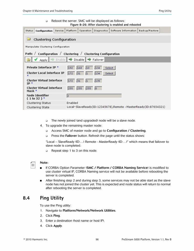
Chapter 8 Maintenance and Troubleshooting Ping Utility
© 2010 Harmonic Inc. 96 ProStream 5000 Platform, Version 1.1, Rev B
❑ Reboot the server. SMC will be displayed as follows:Figure 8-26: After clustering is enabled and rebooted
❑ The newly joined (and upgraded) node will be a slave node.
4. To upgrade the remaining master node:
❑ Access SMC of master node and go to Configuration / Clustering.
❑ Press the Failover button. Refresh the page until the status shows:
“Local – SlaveReady (ID:…) Remote - MasterReady (ID:…)” which means that failover toslave node is completed.
❑ Repeat step 1 to 3 on this node.
Note:
■ If CORBA Option Parameter (SMC / Platform / CORBA Naming Service) is modified touse cluster virtual IP, CORBA Naming service will not be available before rebooting theserver is completed.
■ After finishing step 2 and during step 3, some services may not be able start as the slavenode has not joined the cluster yet. This is expected and node status will return to normalafter rebooting the server is completed.
8.4 Ping UtilityTo use the Ping utility:
1. Navigate to Platform/Network/Network Utilities.
2. Click Ping.
3. Enter a destination (host name or host IP).
4. Click Apply.

Chapter 8 Maintenance and Troubleshooting Ping Utility
© 2010 Harmonic Inc. 97 ProStream 5000 Platform, Version 1.1, Rev B
Figure 8-27: Ping utility

Chapter 8 Maintenance and Troubleshooting Contacting Harmonic Support
© 2010 Harmonic Inc. 98 ProStream 5000 Platform, Version 1.1, Rev B
8.5 Contacting Harmonic SupportThe Harmonic Customer and Technical Support groups are available to help you with anyquestions or problems you may have regarding Harmonic products.
For assistance from within the U.S. and Canada, call toll free:
1.888.MPEGTWO (673.4896)
For assistance from outside the U.S. and Canada, call:
1.408.490.6477
The fax number is 408.490.6770.
The email address is [email protected].
The corporate address for Harmonic Inc. is:
Harmonic Inc.549 Baltic WaySunnyvale, CA 94089, U.S.A.Attn: Customer Support
The corporate telephone numbers for Harmonic Inc. are:
Tel. 1.800.788.1330 (from the U.S. and Canada)Tel. +1.408.542.2500 (outside the U.S. and Canada)Fax.+1.408.490.6708
The web address for Harmonic Inc. is www.harmonicinc.com.

© 2010 Harmonic Inc. 99 ProStream 5000 Platform, Version 1.1, Rev B
Glossary
Acronym Definition
ARP Address Resolution Protocol
ARAP Advanced Resource Allocation Protocol
CIFS Common Internet File System
CO Central Office
CORBA Common Object Request Broker Architecture
CPE Customer Premises Equipment
DHCP Dynamic Host Configuration Protocol
DNS Domain Name System
DRM Digital Rights Management
DSLAM Digital Subscriber Line Access Multiplexer
HDD Hard disk drive
HFC Hybrid fibre coax
IA Intel Architecture
IDP Ingest datapath
IP Internet Protocol
ISA Interactive Services Architecture
LSCP Lightweight Streaming Control Protocol
MPEG Moving Picture Experts Group
MPTS Multi Program Transport Stream
MSMQ Microsoft Message Queue
NGOD Comcast’s Next Generation On Demand
NTP Network Time Protocol
NPVR Network Personal Video Recorder
NVOD Near Video on Demand
OPEX Operating expense
PAT Program Association Table
PID Packet Identifier
POST Power-On Self-Test
PMT Program Mapping Table

Glossary
© 2010 Harmonic Inc. 100 ProStream 5000 Platform, Version 1.1, Rev B
PSIP Program and System Information Protocol
QAM Quadrature Amplitude Modulation
RAID Redundant Array of Independent Disks
RSVP Resource Reservation Protocol
RTSP Real Time Streaming Protocol
SCP Secure Copy
SDX Service Deployment System (Juniper® Networks)
SFS Streaming File System
SIMD Single instruction, multiple data
SMC Server Management Console
SNMP Simple Network Management Protocol
SMP Session Management Protocol
SNC Single node cluster
SOAP Simple Object Access Protocol
SPTS Single program transport stream
SVP Secure video processor
TCP Transmission control Protocol
TD Topology Discovery
UDP User Datagram Protocol
URI Uniform resource identifier
URL Uniform resource locator
USB Universal serial bus
UTP Unshielded twisted pair
VOD Video On Demand
VPN Virtual private network
Acronym Definition

Harmonic Inc.549 Baltic WaySunnyvale, CA 94089, U.S.A.T +1 408 542 2500 F +1 408 490 6708
www.harmonicinc.com
Copyright © 2010 Harmonic Inc. All rights reserved.Manual Part No. MAN-PS5K-PLAT-1.1 REV B