for reactive energy alpican compensation - legrand solutions for reactive energy compensation 2...
TRANSCRIPT
Alp
icAn
tm
EssEntiAl solutionsfor rEActivE EnErgy
compEnsAtion
tHE GLOBAL SPECIALISTin ElEctricAl AnD DigitAl BuilDing infrAstructurEs
EX213003_brochure lancement Alpican_EN.indd 1 31/01/13 14:20

the available power in an electrical supply
system is composed of active power
and reactive power. While active power results
in the form of actual work output, the reactive
power is used to maintain the magnetic field
requirements. the power factor is an indicator
of reactive power which is always an inherent
part of the electrical system.
lower is the power factor higher is the reactive
power usage.
Hence, the challenge is to improve power
factor which helps in reducing i2r losses,
improves voltage stability and increase
utilization of an electrical distribution system.
With legrand’s range of solutions for reactive
energy compensation that include capacitors,
detuned reactors, automatic power factor
controllers and capacitor banks, you will have
the power to contribute to energy savings.
AlpicAntm
improve powerquality to save
energy and reduceenvironmental impact
ca
EX213003_brochure lancement Alpican_EN.indd 2 31/01/13 14:21

al supply
esults
eactive
ain the magnetic field
or is an indicator
ways an inherent
eactive
er
ses,
tribution system.
eactive
apacitors,
or
ou will have
gy savings.
Essential solutions for reactive energy compensation 2product’s benefits 4
Alpican capacitors 6ctX-c contactors 8Alptec power factor controllers 11Detuned reactors 12
index
2-5Wide choice,
energy savingand design
6-12catalogue pages
EX213003_brochure lancement Alpican_EN.indd 1 31/01/13 14:21

AlpicAnTM cApAciTorsthanks to the new Alpican range of aluminiumcan capacitors, you can improve power quality,reduce the active energy losses, improveutilisation of the electrical installation andeliminate penalties.
the other legrand products, such as ctX-ccontactors, detuned reactors or Alptecpower factor controllers allow you to build anefficient solution for the energy compensationin commercial and industrial buildings.
essenTiAl soluTionsfor reAcTive energy
coMpensATion
cTx-cTM conTAcTors DeTuneD reAcTors poWer
selection
WWW.lEgrAnD
2
EX213003_brochure lancement Alpican_EN.indd 2 31/01/13 14:21

To protect Alpican capacitors,please refer to DPX³ dedicated brochure
rs
s poWer fAcTor conTrollers
selection of AlpicAntm rAnge depends on 2 criteriA:
3AlpicAntm
WWW.lEgrAnD.com
essentiAl solutions for reActive energy compensAtion
EX213003_brochure lancement Alpican_EN.indd 3 31/01/13 14:21

Beforeinternal fault
Afterinternal fault
i compAct designAlpican is constructed with threesingle elements stacked andassembled to form a delta connec-tion. the compact design offershigh mechanical strength andstability. it ensures longer lifeto the system and an easy handling.
i explosion proof designin the event of thermal or elec-trical overload, the particulardesign of the capacitor protectsit from an explosion. indeed,the capacitor is disconnectedfrom the circuit and the flow ofcurrent is interrupted.
i self-heAling technologyfor A longer lifein case of voltage breakdownthe metal layer around thebreakdown evaporates.this insulation area allows thefunctioning of the capacitorduring the entire process.
i unique terminunique design ofblock, with pre-mountdischarge resistproper termination of the cthe cable connection is so firmthat it doesn’t allto lose.
i eAse of instAllAcompact cylindricof Alpican makes inseasy & faster. this saving timeand costs makes a perfcombination for the insmounting is done with a sat the bottom of the c
sAfe, reliABle &eAsy To insTAll AluMiniuM
cAn cApAciTors
WWW.lEgrAnD
4
EX213003_brochure lancement Alpican_EN.indd 4 31/01/13 14:21

Beforeinternal fault
Afterinternal fault
energy sAvingi unique terminAl designunique design of ip 20 terminalblock, with pre-mounteddischarge resistor ensuresproper termination of the cables.the cable connection is so firmthat it doesn’t allow the cableto lose.
i eAse of instAllAtioncompact cylindrical designof Alpican makes installationeasy & faster. this saving timeand costs makes a perfectcombination for the installer.mounting is done with a studat the bottom of the capacitor.
i low energy losses(energy sAving)Alpican is designed and madefor long life and low losses duringthe operation.thus making it one of the most energyefficient capacitors.
i impregnAntnon-pcB semi-dry resin reducesthe risks of leaking.
Terminalfor Connection
Mountingstud
5WWW.lEgrAnD.com
product’s benefitsAlpicAntm
EX213003_brochure lancement Alpican_EN.indd 5 31/01/13 14:21
6
Alpican capacittechnical characteris
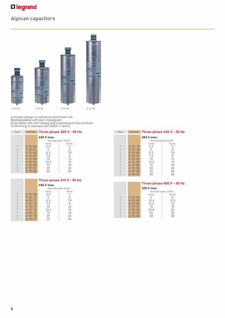
Alpican capacitors
4 151 80 4 151 83 4 151 84 4 151 86
Compact design in cylindrical aluminium canBiodegradable soft resin impregnantDual safety with self healing and overpressure disconnectorConforming to standard IEC 60831-1 and 2
Pack Cat.Nos Three-phase 400 V - 50 Hz
440 V max.Nominal power (kVAr)
50 Hz 60 Hz1 4 151 60 2.5 31 4 151 61 5 61 4 151 62 6.3 7.61 4 151 63 7.5 91 4 151 64 10 121 4 151 65 12.5 151 4 151 66 15 181 4 151 67 20 241 4 151 68 25 30
Three-phase 415 V - 50 Hz456 V max.
Nominal power (kVAr)50 Hz 60 Hz
1 4 151 69 2.5 31 4 151 70 5 61 4 151 71 6.3 7.61 4 151 72 7.5 91 4 151 73 10 121 4 151 74 12.5 151 4 151 75 15 181 4 151 76 20 241 4 151 77 25 30
Pack Cat.Nos Three-phase 440 V - 50 Hz
484 V max.Nominal power (kVAr)
50 Hz 60 Hz1 4 151 78 2.5 31 4 151 79 5 61 4 151 80 6.3 7.61 4 151 81 7.5 91 4 151 82 10 121 4 151 83 12.5 151 4 151 84 15 181 4 151 85 20 241 4 151 86 25 301 4 151 87 30 36
Three-phase 480 V - 50 Hz528 V max.
Nominal power (kVAr)50 Hz 60 Hz
1 4 151 88 5 61 4 151 89 10.4 12.51 4 151 90 12.5 151 4 151 91 15 181 4 151 92 20.8 251 4 151 93 25 301 4 151 94 30 36
n Technical specifica
Discharge resistors:Fitted inside, they discstandards (dischargeLoss factor:Alpican capacitors haThis value leads to a pexcluding the dischargRated frequency: 50/60
Capacitance: tolerance on the capacitance v
Max. permissible volt1.1 Un up to 8 hours dMax. permissible curUp to 1.5 Ir including cIEC 60831-1 and 2)Inrush current: up to 2
Insulation class: 3/15
Standards:Alpican capacitors co• International standarTemperature class:Alpican capacitors aretemperature class• Maximum temperatu• Average over 24 hou• Annual average: 35 °• Lowest temperatureCooling: natural or for
Humidity: max. 95 %
Altitude: max. 4000 m
Mounting position: ve
n Dimensions
FASTermina
Marking
M1216
11.8 ±0.5
H
D
63.5
For capacitors from 2.5
Cat.No Nominalat 50 Hz
4 151 60 24 151 61 54 151 69 24 151 70 54 151 78 24 151 79 5
EX213003_brochure lancement Alpican_EN.indd 6 31/01/13 14:21

7
Alpican capacitorstechnical characteristics
Hz
Hz
n Technical specifications
Discharge resistors:Fitted inside, they discharge the unit in accordance with currentstandards (discharge time, 3 minutes)Loss factor:Alpican capacitors have a loss factor of less than 0.2 x 10⁻³This value leads to a power consumption of less than 0.45 W per kVAr,excluding the discharge resistorsRated frequency: 50/60 Hz
Capacitance: tolerance on the capacitance value: - 5 % / 10 %
Max. permissible voltage:1.1 Un up to 8 hours daily (according to IEC 60831-1 and 2)Max. permissible current:Up to 1.5 Ir including combined effects of harmonics (according toIEC 60831-1 and 2)Inrush current: up to 200 Ir
Insulation class: 3/15 kV
Standards:Alpican capacitors comply with:• International standard: IEC 60831-1 and 2Temperature class:Alpican capacitors are designed for a standard -25Dtemperature class• Maximum temperature: 55 °C• Average over 24 hours: 45 °C• Annual average: 35 °C• Lowest temperature class: - 25 °CCooling: natural or forced
Humidity: max. 95 %
Altitude: max. 4000 m above the sea level
Mounting position: vertical
n Dimensions
FAST-ONTerminal 6.35 x 0.8
Marking
M1216
11.8 ±0.5
H
D
63.5
For capacitors from 2.5 to 5 kVAr - 400 V, 415 V and 440 V
n Dimensions (continued)For capacitors from 6.3 to 30 kVAr - 400 V, 415 V, 440 Vand full range of 480 V capacitors
Marking
H
M12
D
85(1
)
16.8 ±0.5
19.6 ±0.5
16+1
Torque = 1.2 Nm
(1) Seaming adds 4 mm in diameter
Creepage distance:• Φ 63.5 : 10.0 mm
Clearance:• Φ 63.5 : 16.5 mm
Mounting:• Φ 63.5 :
M 12, torque 10 NmTotheed washer J 12.5 DIN 6797Hex nut BM 12 DIN 439
Cat.No Nominal powerat 50 Hz (kVAr)
Dimensions (mm)Weight (kg)
D H max. A
4 151 60 2.5 63.5 129 12 0.4
4 151 61 5 63.5 129 12 0.4
4 151 69 2.5 63.5 129 13 0.4
4 151 70 5 63.5 129 12 0.4
4 151 78 2.5 63.5 129 12 0.3
4 151 79 5 63.5 154 12 0.5
Creepage distance:• Φ 75 / Φ 85 : 9.6 mm
Clearance:• Φ 75 / Φ 85 : 12.7 mm
Mounting:• Φ 75 / Φ 85 :
M 12, torque 10 NmTotheed washer J 12.5 DIN 6797Hex nut BM 12 DIN 439
Cat.No Nominal powerat 50 Hz (kVAr)
Dimensions (mm)Weight (kg)
D H max. A
4 151 62 6.3 75 160 13 0.5
4 151 63 7.5 75 160 13 0.5
4 151 64 10 75 198 13 0.6
4 151 65 12.5 85 198 13 0.8
4 151 66 15 85 198 13 0.8
4 151 67 20 85 273 13 1.1
4 151 68 25 85 273 13 1.5
4 151 71 6.3 75 160 13 0.5
4 151 72 7.5 75 198 13 0.6
4 151 73 10 75 198 13 0.6
4 151 74 12.5 85 198 13 0.8
4 151 75 15 85 273 13 1.2
4 151 76 20 85 273 13 1.2
4 151 77 25 85 348 13 1.5
4 151 80 6.3 75 160 13 0.5
4 151 81 7.5 75 160 13 0.5
4 151 82 10 75 198 13 0.6
4 151 83 12.5 85 198 13 0.8
4 151 84 15 85 273 13 1.2
4 151 85 20 85 273 13 1.2
4 151 86 25 85 348 13 1.5
4 151 87 30 85 348 13 1.6
4 151 88 5 75 160 13 0.5
4 151 89 10.4 85 198 13 0.8
4 151 90 12.5 85 198 13 0.8
4 151 91 15 85 273 13 1.2
4 151 92 20.8 85 273 13 1.2
4 151 93 25 85 348 13 1.5
4 151 94 30 90 348 13 1.5
EX213003_brochure lancement Alpican_EN.indd 7 31/01/13 14:21

8
CTX-C contacttechnical characteris
CTX-C contactors12.5 kVar to 70 kVar three-pole contactors for connecting capacitor banks (400 VA network)
0 296 04 0 296 64 0 297 02
Technical characteristic p. 9Dimensions p. 10
Pack Cat.Nos CTX-C contactors
Three-pole contactors equipped with prefabricatedauxiliary contacts and discharge resistors forconnecting three-phase capacitor banksConform to standards: IEC/EN 60947-1, IEC/EN60947-4-1, IEC/EN 60947-5-1Max. reactive power calculated for an ambienttemperature ≤ 55 °C
12.5 kVAR/25 AMax. reactivepower kVAR Control Voltage
Integratedauxiliary contact Dimensions
1 0 296 02 12.5 110 VA 1 NO + 1 NC Size 11 0 296 04 12.5 230 VA 1 NO + 1 NC Size 11 0 296 05 12.5 440 VA 1 NO + 1 NC Size 1
16.7 kVAR/32 A1 0 296 12 16.7 110 VA 1 NO + 1 NC Size 11 0 296 14 16.7 230 VA 1 NO + 1 NC Size 11 0 296 15 16.7 440 VA 1 NO + 1 NC Size 1
20 kVAR/45 A1 0 296 22 20 110 VA 1 NO + 1 NC Size 21 0 296 24 20 230 VA 1 NO + 1 NC Size 21 0 296 25 20 440 VA 1 NO + 1 NC Size 2
30 kVAR/60 A1 0 296 32 30 110 VA 1 NO + 1 NC Size 31 0 296 34 30 230 VA 1 NO + 1 NC Size 31 0 296 35 30 440 VA 1 NO + 1 NC Size 3
45 kVAR/90 A1 0 296 42 45 110 VA 1 NO + 1 NC Size 41 0 296 44 45 230 VA 1 NO + 1 NC Size 41 0 296 45 45 440 VA 1 NO + 1 NC Size 4
55 kVAR/110 A1 0 296 52 55 110 VA 1 NO + 1 NC Size 41 0 296 54 55 230 VA 1 NO + 1 NC Size 41 0 296 55 55 440 VA 1 NO + 1 NC Size 4
70 kVAR/140 A1 0 296 62 70 110 VA 1 NO + 1 NC Size 51 0 296 64 70 230 VA 1 NO + 1 NC Size 51 0 296 65 70 440 VA 1 NO + 1 NC Size 5
Pack Cat.Nos Replacement coils for CTX-C contactors
For contactors 12.5 kVAR to 20 kVARControl Voltage(50/60 Hz)
5 0 297 01 110 VA5 0 297 02 230 VA5 0 297 80 440 VA
For contactors 30 kVAR5 0 297 05 110 VA5 0 297 06 230 VA5 0 297 81 440 VA
For contactors 45 kVAR to 70 kVAR5 0 297 09 110 VA5 0 297 10 230 VA5 0 297 82 440 VA
n Standards
Conform to standards:
- IEC/EN 60947-4-1
- IEC/EN 60947-5-1
n Power circuit an
PoWeR CIRCuIT (PoLeS)
Nominal Voltage
Nominal insulation Voltagesaccording to IeC 947
Thermal current
Max. operating power at 55ºC
electrical endurance
Max. operations/hour
CoNTRoL CIRCuIT
Standard Voltages
Consumption
INSTANTANeouS AuXILIA
Nominal insulation Voltage
Thermal current Ith
EX213003_brochure lancement Alpican_EN.indd 8 31/01/13 14:21

9
CTX-C contactorstechnical characteristics
TX-C contactors
o 20 kVAR
70 kVAR
n Standards
Conform to standards:
- IEC/EN 60947-4-1
- IEC/EN 60947-5-1
n Power circuit and control circuit characteristics
n Ambient conditions
Storage temperature: - 50 ºC to 80 ºCOperating temperature - 25 ºC to 55 ºC (with no reduction)Working altitude up to 3000 m: with no change in characteristics
n Mounting position
Vertical mounting +/- 30°
25 A 32 A 45 A 60 A 90 A 110 A 140 A
PoWeR CIRCuIT (PoLeS)
Nominal Voltage (V) 690 690 690 690 690 690 690
Nominal insulation Voltagesaccording to IeC 947 (V) 1000 1000 1000 1000 1000 1000 1000
Thermal current (A) 25 32 45 60 90 110 140
Max. operating power at 55ºC
230/240V (kVar) 7.5 10 12.5 20 25 35 45
380/400V (kVar) 12.5 16.7 20 30 45 55 70
660/690V (kVar) 15 20 25 35 55 65 85
electrical endurance (operations) 280.000 280.000 280.000 200.000 150.000 120.000 90.000
Max. operations/hour (operations/hour) 350 350 350 240 150 150 150
CoNTRoL CIRCuIT
Standard Voltages50 Hz (V) 24-690 24-690 24-690 24-690 24-690 24-690 24-690
60 Hz (V) 24-600 24-600 24-600 24-600 24-600 24-600 24-600
Consumption
Frequencycircuit open (VA) 45 45 48 88 191 191 198
circuit closed (VA) 6 6 7 9 15.5 15.5 17
Dual frequency 50 Hzcircuit open (VA) 54 54 58 125 245 245 250
circuit closed (VA) 7 7 8 11.5 20 20 23
Dual frequency 60 Hzcircuit open (VA) 35 35 39 110 215 215 220
circuit closed (VA) 5 5 6 11 15 15 19
INSTANTANeouS AuXILIARy CoNTACT bLoCkS
Nominal insulation Voltage ui (V) 100
Thermal current Ith (A) 10
EX213003_brochure lancement Alpican_EN.indd 9 31/01/13 14:21
10
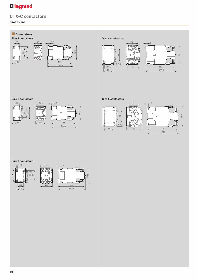
CTX-C contactorsdimensions
n DimensionsSize 1 contactors Size 4 contactors
Size 5 contactorsSize 2 contactors
Size 3 contactors
82.5
45
7350
35
4.5 131
137.5
7.5
85.5
7350
35 45
564.5 133
139.5
7.5
60
90.5
79 50
40
4.5
45
66 144
150.5
55 7.5
118.
5
90
56
60
77 162
168.5
66 9
Ø 5.5
90
128.
5
56 86 172
178.5
75 9
Ø 5.5
Power factor
ALPTEC6
The Alptec power factordisconnection of the steDigital operation ensureand values read, even oConforming to standard61000-4-3, IEC/EN 61000IEC/EN 61000-4-11
Pack Cat.Nos
1 ALPTEC41 ALPTEC61 ALPTEC12
EX213003_brochure lancement Alpican_EN.indd 10 31/01/13 14:21

11
118.
5
62
168.5
128.
5
172
178.5
Power factor controllers AlptecPower factor controllers Alptec
ALPTEC6
The Alptec power factor controller controls the connection anddisconnection of the steps in order to maintain the target power factorDigital operation ensures the accuracy and reliability of the measurementsand values read, even on supplies subject to high levels of interferenceConforming to standards IEC/EN 55022, IEC/EN 61000-4-2, IEC/EN61000-4-3, IEC/EN 61000-4-4, IEC/EN 61000-4-5, IEC/EN 61000-4-6,IEC/EN 61000-4-11
Pack Cat.Nos Power factor controllers
Power supply 230-415 VA - 50/60 HzNumber of steps controlled
1 ALPTEC4 41 ALPTEC6 61 ALPTEC12B 12
n Technical specificationsVersions
Measurements
Temperature class
electrical characteristics
Frequency
Parameters
- Digital power factor controller- Flush-mounting- LED screen: 3 digits, 7 segments- 4, 6 and 12 controlled steps- IP 41 front cover / IP 20 terminal block connections- Relative humidity without condensation: 95 %- RJ 11 connector- TTL standard serial interface- Owner / ModBus RTU communication protocol
- Operation: - 10 to + 50 °C- Storage: - 30 to + 70 °C
- Supply voltage: 230 to 415 VAC- Operating limits (Ue): - 15 to + 10 %- Power consumption L/L - 400 VAC:
5.8 VA (for Alptec4 and Alptec6)6.1 VA (for Alptec12B)
- Immunity time for microbreakings: <6 ms- Rated current (CT): 5 A- Rated reading limits (CT): 0.125 A to 5.5 A- Voltage current limits (Lx/Lx):
180 to 485 VAC (for Alptec4 and Alptec6)195 to 460 VAC (for Alptec12B)
- Electrical insulation: 4 kV- FFT - Harmonic spectrum (THD %): 64 st
50 Hz/60 Hz
Power factor: 0.85 inductive to 0.95 capacitiveAutorecognized capacitor bankAnti-hunting functionFixed step programmableFunction and alarm relay programmableFan relay programmable
ALPTEC4 / ALPTEC6
ALPTEC12B
- Cos ø inductive and capacitive- Phase to phase voltage and currents- Reactive power needed- Cos ø desired- Total harmonic distorsion- Sensitivity- Ambient temperature- Measuring values: True real effective values (TRMS)
Cat.Nos Height x Width x Depth(mm)
Weight(g)
ALPTeC4 96 x 96 x 74 350
ALPTeC6 96 x 96 x 74 370
ALPTeC12b 149 x 149 x 60 700
149
149
149 60
96 96
96 74
EX213003_brochure lancement Alpican_EN.indd 11 31/01/13 14:21

12
Detuned reactorsDetuned reactors
SAH-3.45-20.2
The Alptec detuned reactors are designed to protect the capacitorsagainst harmonics and avoid parallel resonance and amplification ofharmonics flowing on the networkThe connection of these reactors in series with capacitors causes ashift of the resonance frequency of the circuit composed by feedingtransformer-reactors- capacitors so that the resulting self-resonancefrequency is well below the line harmonicsThe blocking factor p% is expressed by the ratio between inductivereactance and capacitive reactance it corresponds to the increaseof voltage applied to capacitors, with respect to line voltage, due tocirculation of capacitive current in the reactorConforming to standards IEC/EN 60289
Pack Cat.Nos Detuned reactors three-phase 50 Hz
Tuning frequency 189 HzP% = 7 / n = 3.78Designed for harmonic level25 % < SH/ST(1) < 50 %To be associated with 440 V / 480 V capacitors
Q (kVar) Associated capacitor1 SAH-4.31-16.2 10 4 151 82/901 SAH-3.45-20.2 12.5 4 151 83/911 SAH-1.73-40.4 25 4 151 86/941 SAH-0.86-80.8 50 2 x 4 151 86/941 SAH-0.58-121.2 75 3 x 4 151 86/941 SAH-0.43-161.6 100 4 x 4 151 86/94
Tuning frequency 135 HzP% = 14 / n = 2.7Designed for harmonic level25 % < SH/ST(1) < 50 %To be associated with 480 V capacitors
Q (kVar) Associated capacitor1 SAH-8.1-15.7 12.5 4 151 901 SAH-4.05-28.9 25 4 151 931 SAH-2.02-62.8 50 2 x 4 151 931 SAH-1.35-94.2 75 3 x 4 151 931 SAH-1-125.6 100 4 x 4 151 93
n Technical specifications
n Installation and requirements
n Dimensions
- Rated line voltage: 400 V / 440 V- Rated frequency: 50 Hz- Tolerance on inductance: 0 / + 6 %- Dielectric test 50 Hz, 3 kV, 60 s, protection class: IP 00- Cooling method: natural air (AN)- Ambient temperature: - 5 to + 40 °C- Elevation above sea level: 1000 m a.s.l- Conform to: IEC 60289 - EN 602 89- Insulation class H- Insulation level 1.1 kV- Blocking factor p% = 7 - Tuning order = 3.78 / p% = 13.7 -Tuning order = 2.7- Thermal protection switch (250 V, 2.5 A) wired on terminal block
- Operation and storage temperature: - 25 to + 70 °C- Selection of the right type according to harmonic pollution- In operation an adequate air circulation must be guaranteed- Windings must be installed vertically for better heat dissipation- The reactor must be protected against overloads and short-circuitsby fuses and/or circuit breakers- Suitable protection against undesired contacts (IP00) must beprovided by means of enclosures or boxes protecting the powersystem where the reactor is installed- It is imperative to that the thermal N.C dry contact be connected inseries with the contactor coil, in order to disconnect the step in caseof overheating
Aluminium bars
Cat.Nos Q(kVar)
Ln(mH)
I RMS(A)
Ptot(W)
Dimensions(mm)
Weight(kg)
L W HSAH-4.31-16.2 10 4.31 16.2 85 180 140 190 11
SAH-3.45-20.2 12.5 3.45 20.2 105 180 140 190 11
SAH-1.73-40.4 25 1.73 40.4 210 240 140 255 17
SAH-0.86-80.8 50 0.86 80.8 270 240 165 280 28
SAH-0.58-121.2 75 0.58 121.2 400 300 190 315 40
SAH-0.43-161.6 100 0.43 161.6 425 320 210 315 50
SAH-8.1-15.7 12.5 8.1 15.7 130 240 140 220 14.5
SAH-4.05-28.9 25 4.05 28.9 225 240 160 240 22
SAH-2.02-62.8 50 2.02 62.8 395 300 180 315 38
SAH-1.35-94.2 75 1.35 94.2 475 320 210 325 51
SAH-1-125.6 100 1 125.6 615 360 210 375 65
BL
A B C
C1B1A1
H
1: SH = Power (kW) of loads generating harmonicsST = Power (kVA) of transformer
EX213003_brochure lancement Alpican_EN.indd 12 31/01/13 14:21

ss: IP 00
p% = 13.7 -
on terminal block
0 °Cnic pollutione guaranteedheat dissipationds and short-circuits
(IP00) must betecting the power
act be connected innect the step in case
Dimensions(mm)
Weight(kg)
L W H180 140 190 11
180 140 190 11
240 140 255 17
240 165 280 28
300 190 315 40
320 210 315 50
240 140 220 14.5
240 160 240 22
300 180 315 38
320 210 325 51
360 210 375 65
B
EX213003_brochure lancement Alpican_EN.indd 3 31/01/13 14:21

EX21
3003
-JA
nu
Ary
2013
folloW usAlso on
website: www.legrand.com
www.twitter.com/legrand
www.youtube.com/legrand
World Headquartersand international Department87045 limoges cedex - france% : + 33 (0) 5 55 06 87 87fax: + 33 (0) 5 55 06 74 55
EX213003_brochure lancement Alpican_EN.indd 4 31/01/13 14:21