for surgical rooms, hospital facilities and clean rooms · for surgical rooms, hospital facilities...
TRANSCRIPT

AIR CONDITIONERSfor surgical rooms, hospital facilities and clean rooms
TECNAIR LVSURGICAL ROOM AIR CONDITIONING
ISO 9001Cert. n° 273GOST certification
TECNAIR LV S.p.A.
21040 Uboldo - Varese - ItalyVia Caduti della Liberazione, 53
Phone + 39 02.96.99.11.1Fax. + 39 02.96.78.15.70E-mail: [email protected]
www.tecnairlv.it
TECNAIR LVSURGICAL ROOM AIR CONDITIONING
7615
0207
C.0
413
TECNAIR LV has a policy of continuous development, so the company reserves the right to modify and improve any product described in this document without notice. Technical data and dimensions are not binding.

TECNAIR LVCLOSE CONTROL AIR CONDITIONERS
serieH
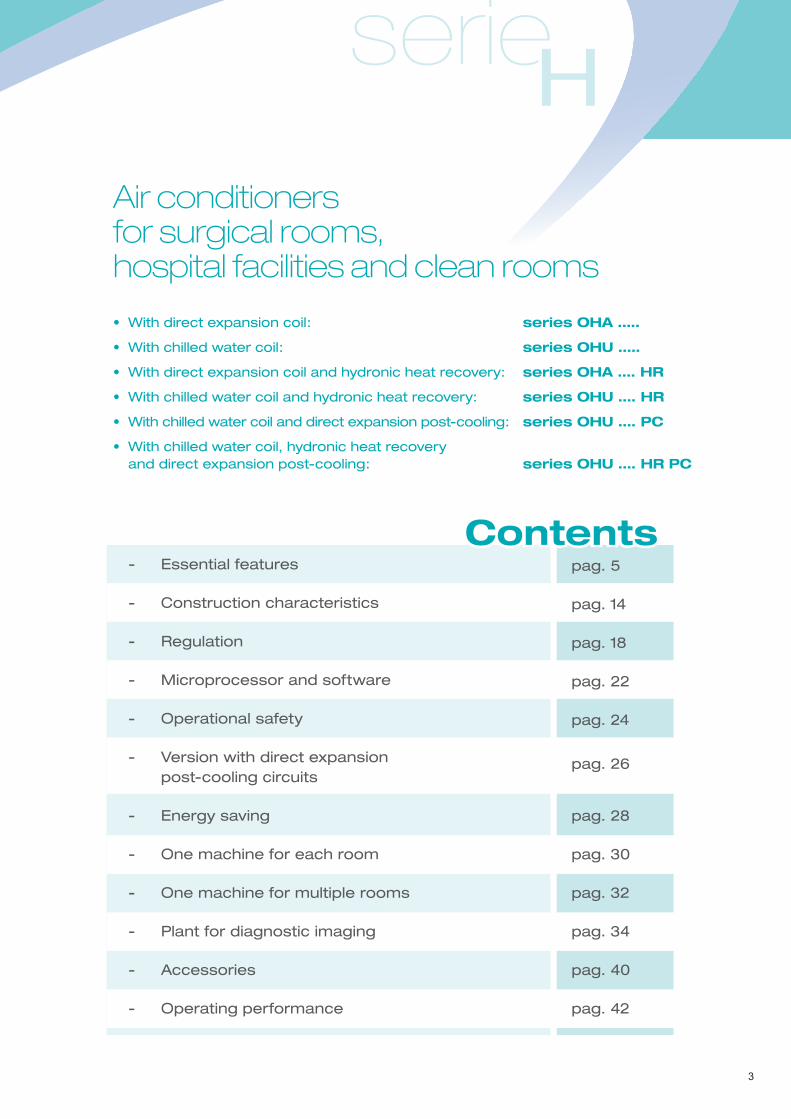
serieHAir conditioners for surgical rooms, hospital facilities and clean rooms
• With direct expansion coil: series OHA …..
• With chilled water coil: series OHU …..
• With direct expansion coil and hydronic heat recovery: series OHA …. HR
• With chilled water coil and hydronic heat recovery: series OHU …. HR
• With chilled water coil and direct expansion post-cooling: series OHU …. PC
• With chilled water coil, hydronic heat recovery and direct expansion post-cooling: series OHU …. HR PC
- Essential features
- Construction characteristics
- Regulation
- Microprocessor and software
- Operational safety
- Version with direct expansion post-cooling circuits
- Energy saving
- One machine for each room
- One machine for multiple rooms
- Plant for diagnostic imaging
- Accessories
- Operating performance
pag. 5
pag. 14
pag. 18
pag. 22
pag. 24
pag. 26
pag. 28
pag. 30
pag. 32
pag. 34
pag. 40
pag. 42
Contents
3

4
5
serieH
Essential features
General information
- For the treatment of full fresh air or with
partial recirculation.
- Available static pressure selectable from
250 to 1,000 Pa depending on the type
of plant and the need to install absolute
filters after the unit.
- Section for air suction from the rooms,
partial recycle or total exhaust to the
outside.
- Static or dynamic management of
overpressure or depression in the
controlled room compared to a reference
environment.
The units are equipped with controls,
electrical panel, microprocessor and
dedicated software. They can be expressly
customized for:
- General surgery rooms
- Orthopaedic surgery rooms
- Very low-temperature heart surgery rooms
- Intensive care units
- Sterilization rooms
- Diagnostic imaging rooms
- BSL laboratories for the treatment of viruses or
substances which are toxic, radioactive,
nuclear, flammable or contaminating in
general
- Hospital wards
- Dental surgeries
- Biotechnology laboratories
- Anatomical pathology laboratories
- Mortuary chambers.
GOST certificationISO 9001
Cert. n° 273
6
For more than ten years Tecnair LV SpA has
been the European leader for the design and
construction of specialized air conditioners for
surgical rooms. Its “H” Series, equipped with
controls, microprocessor and software, has
been revised so that it can also be used in other
specially delicate applications with different
characteristics such as diagnostic imaging
rooms, intensive care units, wards etc.
In fact, in these applications where there is
neither open wound nor high-level environmental
contamination,absolutefiltersarenotnecessary
either at air supply or suction, and therefore
neither is high static pressure for the supply fan
and the suction/exhaust fan.
The standard version of the new “H” Series air
conditioners for surgical rooms, hospital facilities
and clean rooms has low static pressure of
approximately 250-300 Pa on both the supply
and suction fans. High performance fans can be
provided as accessories: up to 1,000 Pa, with
epoxypaintingofthefinsinordertosatisfyeven
the most critical applications.
In practice, the entry level unit (which is in any
case dimensioned to treat full or almost full fresh
air) is suitable for diagnostic imaging rooms or
hospital wards. With the appropriate options
added, the unit can be configured to fulfil the
requirements of the most demanding plant
design conditions such as those for surgical
rooms where highly specialized operations are
to be performed.
TUV Certification Compliance with Standard DIN 1946/4
The “H” Seriesairconditioners,configuredwith
the accessories mentioned above, conform to
the German Standard DIN 1946 part 4. They are
certifiedtobeincompliancebyTUV.
serieH
Version with chilled water coil: OHU
Uses the water supplied from a remote chiller
as the source of cooling. Equipped with a three-
way regulation valve as standard (two-way
accessory) controlled by microprocessor.
Version with direct expansion circuit: OHA
The “H” Series air conditioners with direct
expansion coil are equipped with one or two
independent cooling circuits. Low noise, high-
efficiency, scroll-type compressors are used.
The standard expansion valve is electronic and
can therefore guarantee maximum control of
the temperature with minimum energy
consumption and effective antifreeze control of
the evaporating coil.
The cooling circuits have all the components
necessary for regulation, protection and safety.
They are positioned, together with the electrical
panel and all the controls, in a technical
compartment on the right side, out of the treated
airflow. They use the ecological refrigerant
R410A which is completely harmless to the
ozone layer and has a very low impact on the
environment. The OHA models to be matched
with remote condensers are supplied with a
nitrogen pressurization charge. The final
charge together with any oil top-up is done by
the installer on-site. The refrigerant and oil
charges are done in our factory if the water
cooled condenser (accessory) is incorporated.
Easy hygienization and sterilizationAll the internal components of the “H” Series air
conditioners which are in direct contact with the
airflowcaneasilyberenderedhygienicasthey
can be reached and extracted by simply opening
the access doors.
The entire machine is made accessible in this
way. This means that maintenance and cleaning
operations can be carried out correctly as
scheduled, easily and quickly.
7

No risk of Legionella Pneumophila
During the design and construction of the “H”
Series air conditioners, all possible measures
have been taken to exclude any chance of the
formation of Legionella Pneumophila bacterial
colonies inside the unit. Very high-level interior
conditions of hygiene are ensured by the
materials used, the easy cleaning of the most
at-risk components, and the units’ operating
ranges.
High quantity constant fresh air flow
Chemical contamination, present in particular
in surgical rooms, cannot be filtered out but
must be diluted with large quantities of constant
freshairflow.Themanagementoftheairflowis
entrusted, via a microprocessor, to an inverter
which controls the rotation speed of the air
supplyfandependingontheairflowsettingand
the degree of clogging of the machine’s own
filtersandotherfiltersexternaltoit.Thedesired
air flow is directly selectable by the user and
can vary from a minimum to a maximum value
according to the model of the air conditioner.
Very high air filtration
To prevent airborne bacterial contamination of
theroom,thefreshairflowispassedthrough,
in compliance with the applicable Regulations,
standard G4 efficiency filters at the air intake
of the machine (F7 as an accessory) and
through F7 standard post-filters (F9 as an
accessory) after the fan at the entrance of the
air supply ducts. AnM5 filter is also provided
at the entrance of the suction air duct before
the exhaust fan in order to keep the interior of
the machine clean. The standard unit supplies
approximately 250/300 Pa and can reach
the 800/1,000 Pa static pressure (accessory)
necessary for the essential sound damper
and any terminal absolute filter. If this filter is
8
serieH
present, it has to be installed directly in the room
to be controlled as any other aeraulic element
after itmay contaminate the air flow.Selecting
high static pressure exhaust fans also allows
the installationofanabsolute filterat the inlet
of the re-suction air ducts before the sound
damper; this, together with the management
of the depression in the room, is necessary in
order to avoid polluting the external environment
if toxic substances are to be treated or septic
operations carried out.
Indoor or outdoor installation
The air conditioners have been designed for
both indoor and outdoor (accessory) installation.
Their extreme compactness, reduced noise
level and pleasing appearance all make them
suitable for installation near the rooms to be
conditioned, thus avoiding lengthy expensive
duct work. External installation however requires
the air conditioners to be positioned under a
protective canopy to ensure comfortable access
when maintenance has to be performed during
bad weather.
Easy installation
The machine has been designed to be easy
to install. Once positioned where it is to be
installed, it only needs electrical, hydraulic,
cooling, ducting and remote accessory
connections. The relevant manual gives all
the necessary procedures for the perfect
installation, subsequent checking and final
testing of the equipment.
9
10
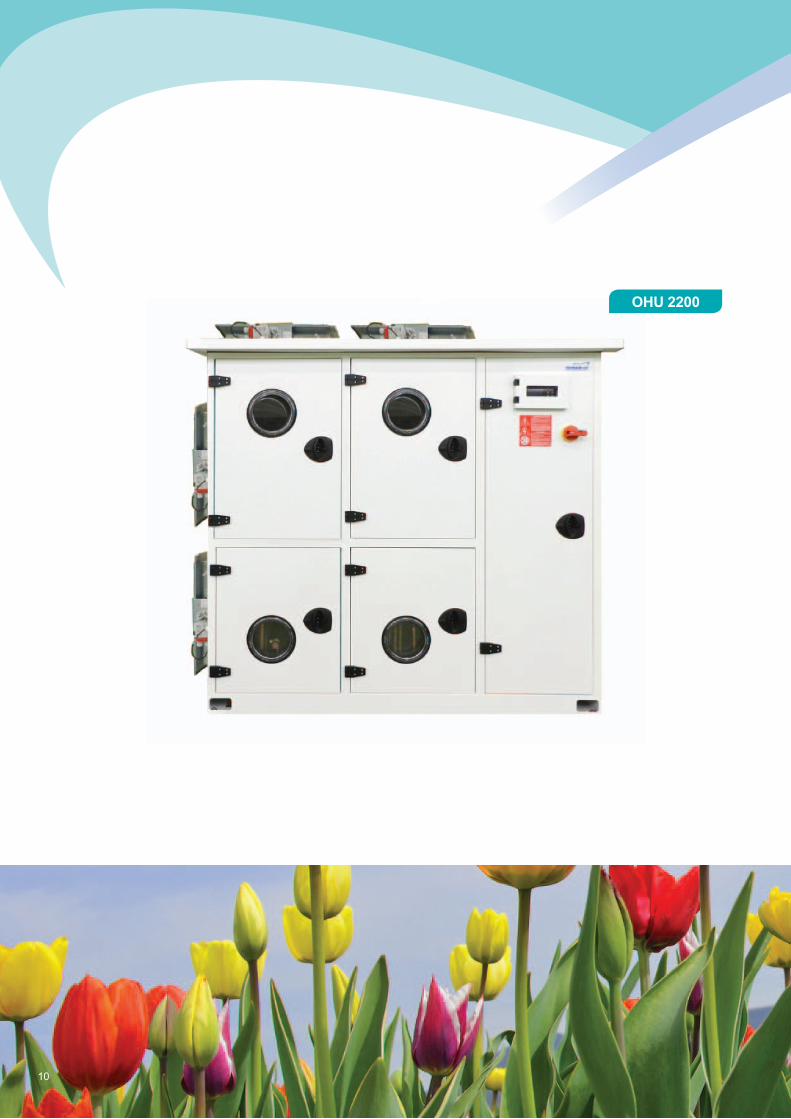
OHU 2200
serieH
11
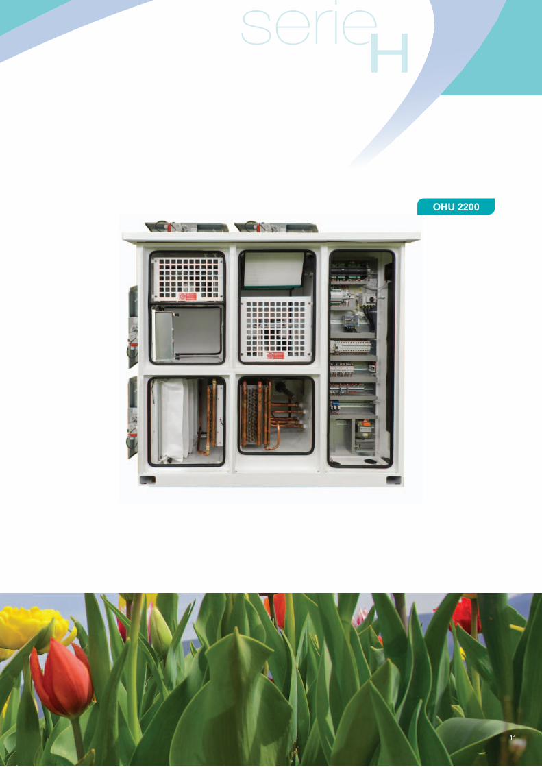
OHU 2200

12
OHU 2200 HR
serieH
13
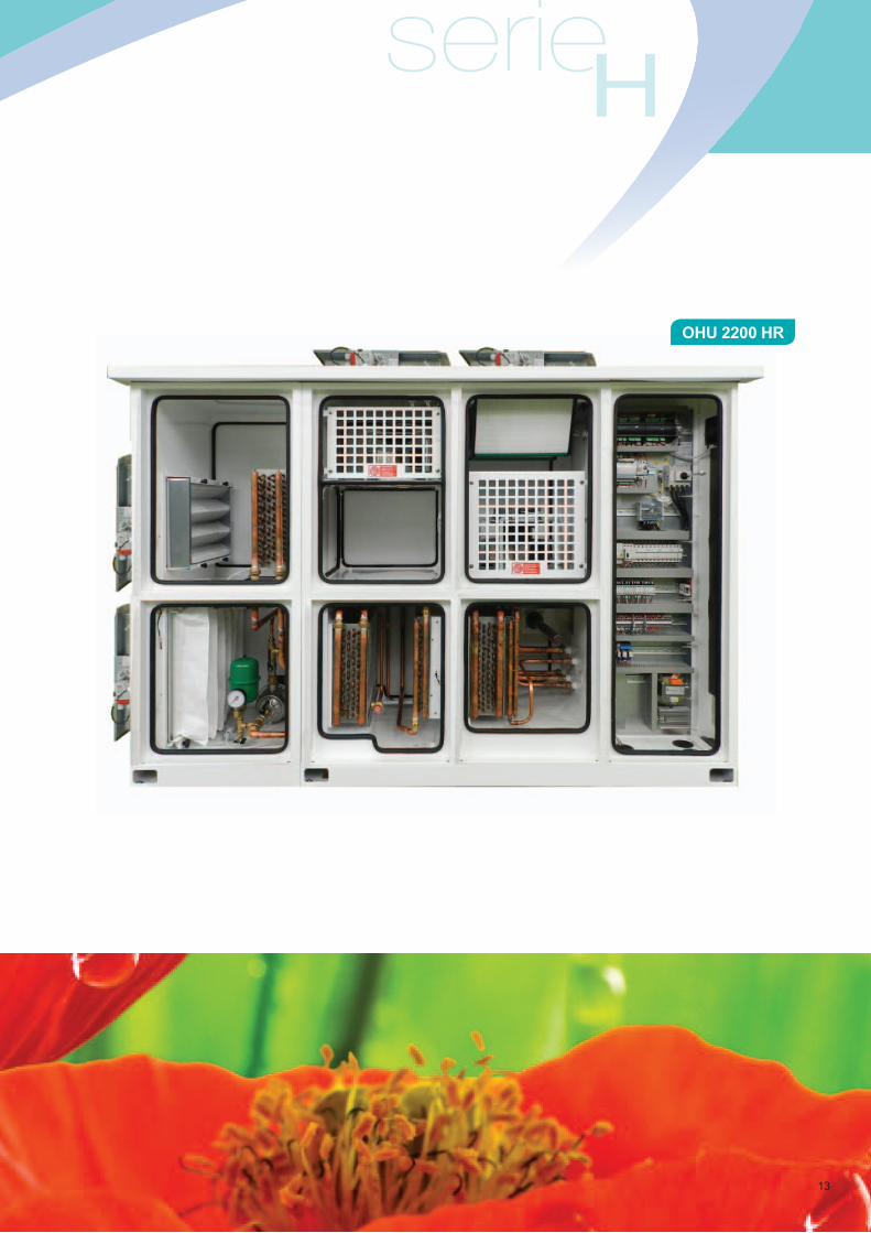
OHU 2200 HR
Construction characteristicsStructure of the unit
The structure is made of welded metal plates
which are surface treated with epoxy-resin
paint (60 microns, white) after cataphoresis.
The panels are double-skinned, 50mm-thick
sheet steel. They are painted white as above
and have an internal sandwich layer of heat and
sound insulation in rock wool (fire resistance
class 0). The internal panel can be supplied in
stainless steel if requested as an accessory.
The supply and exhaust air outlets are upper,
vertical, in the standard version; they can as a
variation be rear, horizontal. In this case, the
air supply filter is installed in the appropriate
canister provided, to be installed on site on
the outside of the unit. The front panels have
inspection portholes positioned so that the
interior of the machine can be checked without
opening and therefore stopping it. It should
be remembered that in some cases such as
surgical rooms, these machines must operate
continuously so that they do not lose their
overpressure and compromise the air quality.
The panels can be opened by keys for access
and maintenance and the closing mechanisms
can also be padlocked for greater safety. The
panels have elastomer seals which do not react
with sterilizing agents.
Air supply fan section
This section has either one or two plug fans with
electronic speed control to guarantee constant
airflow even if the filters become increasingly
clogged, increasing their pressure drop.
Double fans can also be provided as an
accessory for use in emergency.
14
serieH
Return and exhaust fan sectionAlso this section has either one or two
inverter-controlled plug fans to guarantee
the required level of overpressure or
depression in the area to be controlled.
The standard external static pressure of the
suction/exhaust fans is approximately 250 Pa.
Fans with much higher static pressure can be
installed (accessory) in order to manage, for
example, external absolute filters: infectious
departments etc. Double fans, with double
inverters, can also be provided for use in
emergency.
Version without exhaust fan section
A version without the return and exhaust fan
section (accessory) is available for installations
where the quantity of fresh air is limited to that
necessary for the pressurisation of the room,
without any provision for exhaust.
Motorised dampers on fresh air inlet and gravitational dampers on the exhaust outlet
To prevent the wind from blowing pollution
into the machine during shutdown.
Motorised dampers on all ventsMotorised dampers (as accessories) can be
fitted to the vents going to and coming from
the controlled room. In this case the standard
gravitational supply damper is substituted with
a motorised version.
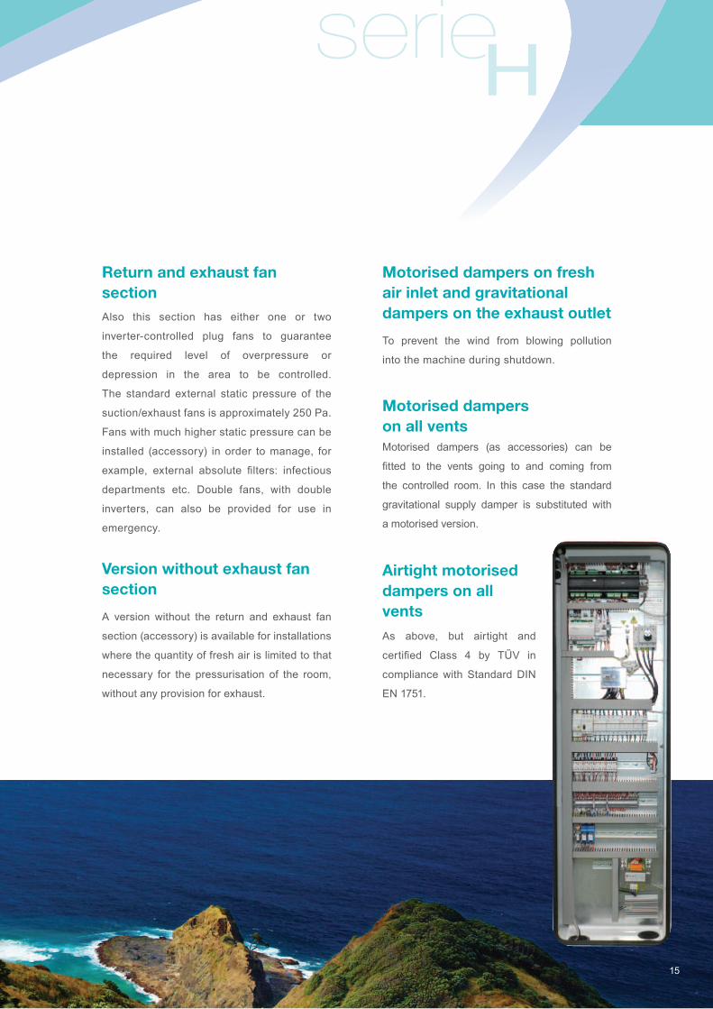
Airtight motorised dampers on all vents
As above, but airtight and
certified Class 4 by TŰV in
compliance with Standard DIN
EN 1751.
15
Motorised recirculation damper For partial recirculation installations, a
motorised by-pass modulated damper
(accessory) is available counter-opposed to
the fresh air one. This saves a considerable
amount of energy and reduces running costs
significantly.Whentherecirculationdamper is
fitted,thefreshairfilterissubstitutedwithother
pleatedfiltersofefficiencystandardG4orF7
(accessory) in order to improve the size of the
section for mixing with the fresh air.
Differential pressure sensor for each filter
Eachfilteringsectionofthemachineisequipped
with a differential pressure sensor which can
be set to signal the level of filter clogging via
microprocessor. As an alternative, pressure
sensors can be supplied which not only signal
the alarm via microprocessor but also provide
an analogue indication of the level of clogging.
In this case, the pressure sensors are located
on the outside of the electrical panel.
Immersed-electrode humidifier
The standard humidification system is the
immersed-electrode type. A characteristic of
thesehumidifiersistheproportionalproduction
of steam between 10% and 100% of their
capacity. The capacity of the humidifier can
be selected depending on the quantity and
condition of the fresh air.
Immersed-resistance humidifier
This accessory can guarantee excellent
performance even when using water which
is low in mineral salts, is demineralized or is
generally of poor quality.
16
Centralised steam system regulation and distribution
If the Hospital has a centralised steam
distribution system at a pressure of 1 bar
(relative), a stainless steel steam controller and
distributor can be installed as an option. This
system allows modulation of the steam supply
from 0% to 100%.
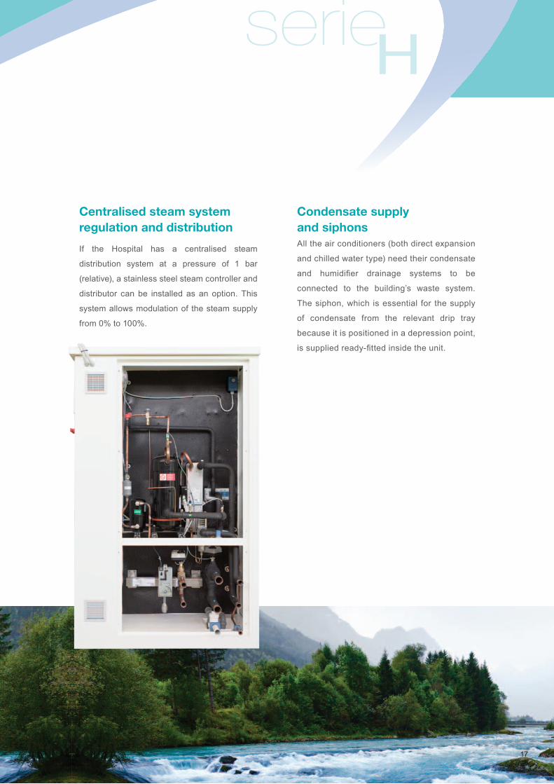
Condensate supply and siphonsAll the air conditioners (both direct expansion
and chilled water type) need their condensate
and humidifier drainage systems to be
connected to the building’s waste system.
The siphon, which is essential for the supply
of condensate from the relevant drip tray
because it is positioned in a depression point,
issuppliedready-fittedinsidetheunit.
17
serieH
RegulationTemperature and humidity sensors
The control of the unit is based on the
information from the temperature and humidity
sensors. In the standard machines, these are
installed in the air suction and exhaust sections.
Alternatively, TECNAIR LV can install
the temperature sensor in the supply fan
compartment and the humidity one in the re-
suction compartment. The sensors can also be
supplied loose, unfitted, so that the customer
can install them in the controlled room or in
the re-suction ducts. Each different solution
is best suited to a particular type of system.
The advantages and disadvantages of each
solution are specified in the unit installation
instruction manual.
Static control of overpressure or depression
This is to prevent any kind of contamination
entering or leaving the designated space.
The static control of overpressure or depression
(standard) is carried out by respectively
reducing or increasing the re-suction fan
airflowusingmanualsettingsoftheelectronic
control of the fan. This regulation, which is
perfectly adequate for hospital wards for
example,isnotsufficientforareaswithhigher
air quality requirements such as surgical rooms
or infectious wards.
18
serieH
19
Dynamic control of overpressure or depression
(Accessory) A crucial and sophisticated
characteristic of the “H” series air conditioners
is its ability to automatically control two
different operating ranges of overpressure
or depression of the room compared to the
surrounding areas. Via the provided differential
pressure sensor to be installed between the
controlled room and a nearby area, and thanks
to the electronically controlled exhaust fan, the
microprocessor can control:
- overpressure,byreducing theexhaustairflow
compared to that introduced, which must
remain constant. This makes it impossible for
airborne particles and pathogens to enter the
room from the surrounding areas. If doors are
kept open, the microprocessor reduces the
exhaustairflowtocreateanaircurrentwhich
has to exit through the door, thus preventing
the entrance of any type of particle.
- Depression, by increasing the exhaust
airflow compared to that introduced. This
prevents pathogens or toxic substances
escaping to the outside areas. Obviously,
a room in depression is not protected from
theinfiltrationofcontaminants,soithastobe
perfectly sealed and connected to the outside
through an overpressure filter zonewith an
interlockingdoorsystem.Thefilterzonecan
be supplied by the same air conditioner.
Management of constant pressure airflow in the supply duct
If a single unit has to supply more than one
room (see design), the control of constant
pressureairflowinthesupplyductingisessential
(accessory). To do this, Tecnair LV installs a
differential pressure sensor on the air outlet vent
of the machine. It monitors the internal pressure
of the supply duct and communicates this data
to the microprocessor which compares it to the
set point and accordingly changes the fan speed
in order tobring the supplyairflowback to the
required level.
Pressure sensor to read the airflow with constant pressure control
If constant pressure regulation in the supply
ducts is selected, a pressure sensor is available
as an accessory which permits the real-time
readingoftheconcurrentairflow.Theaccessory
simplifiestheregulationofthemachineduring
start-up and maintenance.
Constant depression control in the suction ducts
(Accessory). In units with constant pressure
control in the supply ducts, the room pressure
also has to be controlled to maintain constant
pressure inside the suction ducts. Motorized
VAV boxes in the suction ducts to control
overpressure and post-heating coils (supply
not included) must be installed, one for each
controlled room. This system is indispensable if
a single machine has to supply more than one
room and manage overpressure or depression,
one independently of the other.
20
serieH
Integrated temperature and humidity control
The standard machines are equipped with
all the components necessary to regulate
cooling, heating, humidification and
dehumidification. These components are
sized for the treatment of full fresh air or with
partial air recirculation, and in particular:
- Hot water heating coil with modulating control
valve.
- Chilled water cooling coil with modulating
valve,OHUSeries,orasanalternative.
- Direct expansion coil with cooling circuit,
OHA Series.
- Post-heating coil: hot water coil with three-
way modulating valve for machines with
chilled water cooling coils; electric modulating
as an accessory. Electric modulating coil as
standard for direct expansion machines.
- Independent modulat ing immersed-
electrodehumidifier,immersed-resistenceor
as an alternative.
- Modulating centralized steam distribution
system.
Modulating regulation of the cooling capacity: OHU(for machines with chilled water coil)
The three-way valve (two way as accessory),
controlled by microprocessor, allows perfect
modulating regulation of both cooling and
dehumidification.
Modulating regulation of the cooling capacity: OHA(for machines with cooling circuit)
The standard electronic expansion valve
guarantees reasonable control of the cooling
capacity. If the required temperature tolerance
is very tight, or if a lot of, or indeed full, fresh air
is treated, the accessory to control the cooling
capacity of the compressor can be installed.
This is able to modulate the capacity between
100% and 10% of the nominal capacity of
the circuit.
21
Microprocessor and softwareAll operating and safety functions of the
“H” Series air conditioners are managed by the
standard microprocessor. This allows the
temperature and relative humidity to be
controlled in three ways: proportionally,
proportional-integrally or proportional-integral-
derivatively. PID activation is assisted by an
auto-tuning programme. The control of relative
humidity is proportional. The microprocessor
also controls overpressure and depression and
can be easily connected to the BMS of all the
major constructors.
Serial communication and supervision system: BMSWith the development of BMS (Building
Management System), the problem of
communication between the control systems
of different companies becomes ever more
frequent. Today in fact, it is not only the
quality and reliability of the instruments that
is important, but also the degree of external
connectability that they can offer.
This is why the controls used by TECNAIR LV
today can:
- Be integrated into a system consisting of
instruments from different constructors which
share information via the integrated RS485
Modbus card and a gateway specifically
designed for BACnet and LonWorks
(accessories).
22
serieH
- Be managed remotely through a specific
gateway (accessory), via modem and internet
using a simple browser.
- Inform authorised personnel wherever they
areofanyalarmsituationsthroughaspecific
gateway (accessory), also by SMS.
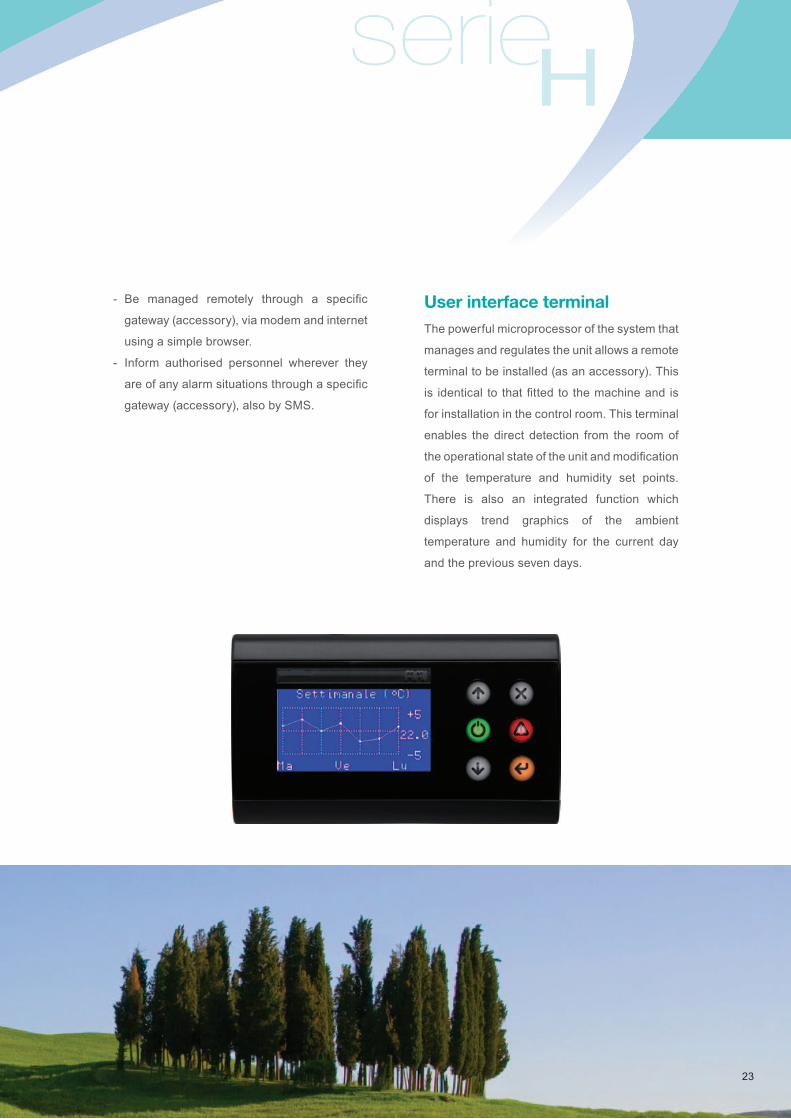
User interface terminal The powerful microprocessor of the system that
manages and regulates the unit allows a remote
terminal to be installed (as an accessory). This
is identical to thatfitted to themachineand is
for installation in the control room. This terminal
enables the direct detection from the room of
theoperationalstateoftheunitandmodification
of the temperature and humidity set points.
There is also an integrated function which
displays trend graphics of the ambient
temperature and humidity for the current day
and the previous seven days.
23
Emergency activation system of room depression Can be activated through a digital port. Enables
the ambient pressure setting to be forced
immediately in order to obtain depression
compared to the surrounding rooms and so
avoid any infective agents being spread if they
are detected during normal operations.
Operational safetyThe “H” Series air conditioners have been
designed, from both the mechanical and
software points of view, to guarantee maximum
operational reliability and therefore to avoid any
risk of suspending a surgical operation in
progress.
Complete electrical panelThe electrical board is equipped with a door-
locking main switch and all the components
necessary for the protection and normal
operation of the unit.
There are terminals for the remote connection
of a cumulative alarm signal and others for the
remote control of start-up and stop functions.
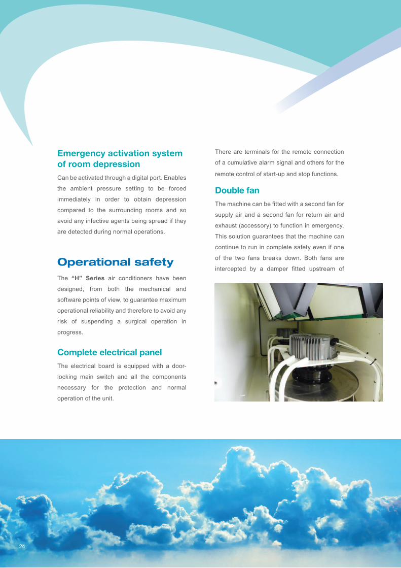
Double fan Themachinecanbefittedwithasecondfanfor
supply air and a second fan for return air and
exhaust (accessory) to function in emergency.
This solution guarantees that the machine can
continue to run in complete safety even if one
of the two fans breaks down. Both fans are
intercepted by a damper fitted upstream of
24
serieH
them to prevent recirculation if only one of
them is in operation. The two fans are controlled
by microprocessor via the electronic regulation
of their rotation speed, based on the
measurementoftheinternalairflowoftheunit.
They provide the total nominal airflow of the
machine. If one of the fans breaks down, the
microprocessor registers the reduced airflow
and increases the speed of the other to
guarantee the maximum airflow compatible
with one-fan operation, in any case equal or
very close to the nominal value.
Uninterruptible power supply: UPSTwo terminals are available on the electrical
panel to be connected to a clean contact of the
continuity group or generator so that, if the
voltage is interrupted, the microprocessor stops
the operation of components which are not
indispensablesuchascompressors,humidifiers
and electrical coils, leaving in operation only
the supply fans, the suction and exhaust fan
and the regulation.
Antifreeze systemThis system guarantees active protection
from the risk of freezing thanks to the
presence of a relative temperature sensor,
installed downstream of the pre-heating coil
and upstream of the cooling one. If the
antifreeze sensor detects a temperature
below that of a pre-set value, it activates
emergency intervention by opening the
heating 100%. If after a set amount of time
the temperature is still under the alarm level,
the fresh air damper is closed and fans are
switched off. The anomaly is displayed on
the main mask of the microprocessor. The
fans start again as soon as the temperature
returns above the pre-set value.
25
Version with direct expansion post-cooling circuits
For very low temperature rooms: heart surgery
For some specialized operation procedures, in
particular for heart surgery with extracorporeal
blood circulation, ambient conditions are
required to be at 16-18°C with humidity not over
55%. These conditions need cold air exiting the
coil at about 6-7°C which is obviously not
obtainable using chilled water at 7/12°C. It is
therefore necessary, downstream of the
standard chilled water cooling, to carry out a
direct expansion post-cooling treatment which,
using a specific cooling circuit, permits the
necessary outlet conditions to be reached in
order to satisfy the requirements. Air enters the
post-cooling coil at 12-13°C saturated, and exits,
still saturated, at 6-7°C; then the standard post-
heating coil corrects the temperature to obtain
the desired conditions. This cooling circuit
complete with all its regulation and control
components, is installed in the technical
compartment of the machine and managed by
the machine’s microprocessor. The axial-fan
type air cooled condenser is installed outside
and has to be connected to the cooling circuit on
site. Alternatively, a water cooled condenser can
be installed inside the machine, connected to
tower water, mains drinking water or directly to
the water from the chillers. In the last two cases,
a pressure sensor is necessary for the
condensing regulation. The circuit operates at
critical temperatures which could bring about a
risk of freezing the condensate on the coil with
the consequent shut down of the machine itself.
However, rigorous precautions are provided to
guarantee the elimination of this risk.
Or to be integrated with the capacity of the
chilled water circuit
This version has very useful applications in
Hospitals where, due to thermal overload or
because of the long distance between the
installation and the chiller, the temperature of
the water is two, three or four degrees above
that intended and therefore the machine is not
capable of guaranteeing all the capacity
necessary for the required cooling and
dehumidification.
26
serieH
27
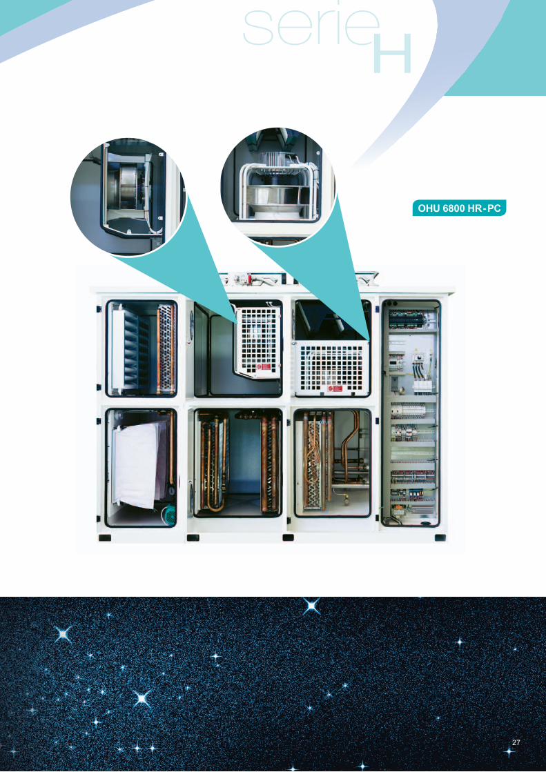
OHU 6800 HR - PC
28
Energy savingNight stand-by Whentheroominnotinusetheflowoffreshair
can be reduced to set limits, maintaining the
area in overpressure and increasing the interval
of inactivity for the control of temperature and
humidity. The room is thus kept sterile without
wasting energy. It should be noted that the
supplyairflowreductioncanonlybecarriedout
if the dynamic control of overpressure has been
selected as the room would otherwise go into
depression. This important function, provided for
in the standard software and managed by the
microprocessor, can be called up manually, via
BMS or time slots. In emergency operations the
stand-by can be deactivated in order to return
the unit rapidly to standard function values.
Versions with hydronic heat recovery systemMade up of two water coils, one in the suction
section and an identical one in the fresh air
treatment section, connected by a hydraulic
circuit with pump and expansion tank. The
microprocessor starts the pump when the
temperatures are favourable to energy saving.
The hydraulic circuit is supplied empty as the
percentage of glycol has to be determined as a
function of the minimum temperature of the
placeof installation. Itmust thereforebefilled
on site to guarantee correct operation.
The hydronic heat recovery system, although
its performance is lower than that of a counter-
current plate or rotary system, is capable of
avoiding every type of cross-contamination
between exhaust air and supply air.
System for the deactivation of components depending on the fresh air temperature Depending on the temperature of the fresh
air, the operation of some components
which correct it is inhibited in order to avoid
wasting energy.

serieH
29

30
One machine for each room
The most modern air conditioning plant
technology calls for one machine to be installed
in each surgical room. This makes it easy to
manage the temperature and humidity required
by the type of operation being carried out. In
addition, the night-time stand-by can therefore
be managed to provide maximum energy
efficiencybecausetheindividualroomdoesnot
have to be tied to the operation of any other
rooms and can exploit to the maximum the
opportunity of being ventilated with untreated
air: for the same reasons it can also be sterilized
without affecting the working operation of the
other rooms. It is also worth taking into
consideration the fact that, in the event of a
machine component breaking down, only one
room would be put out of action. Finally, this
plant design philosophy makes the ducting and
regulation much simpler. Also the financial
savings at first installation are not what they
initially seem. In fact, the economic advantage
of installing only one machine instead of three
is greatly scaled down by the cost of additional
components, the installation of many regulation
systems(possiblyinthedifficult-to-get-atfalse
ceiling space) and by the management
problems of a more complex plant. For
example, in the case of an operating block with
six surgical rooms the optimum solution is to
provide six identical installations - one for each
room - and a seventh for all the ancillary rooms.
The six machines are normally without heat
recovery systems while the seventh has also an
emergency double fan section for both supply
and return/exhaust air.
serieH
31
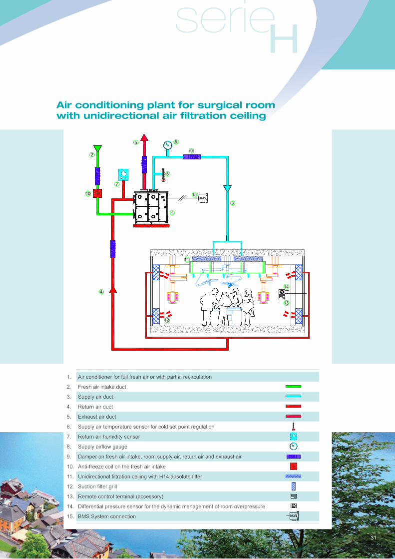
Air conditioning plant for surgical room with unidirectional air filtration ceiling
1. Air conditioner for full fresh air or with partial recirculation
2. Fresh air intake duct
3. Supply air duct
4. Return air duct
5. Exhaust air duct
6. Supply air temperature sensor for cold set point regulation
7. Return air humidity sensor
8. Supplyairflowgauge
9. Damper on fresh air intake, room supply air, return air and exhaust air
10. Anti-freeze coil on the fresh air intake
11. UnidirectionalfiltrationceilingwithH14absolutefilter
12. Suctionfiltergrill
13. Remote control terminal (accessory)
14. Differential pressure sensor for the dynamic management of room overpressure
15. BMS System connection
32
One machine for multiple rooms
It is possible however, if the layout of the plant
requires it, to install a single air conditioner to
serve several rooms. The following regulation
systems have to be provided:
- supplyairflow:controlledbythemicroprocessor
to maintain constant pressure in the relative
ducting. This means that if one of the controlled
rooms is closed and the pressure rises, the
microprocessor reduces the rotation speed so
astoguaranteeconstantairflowtotherooms
which remain open.
- Supply air temperature: controlled to set
point, through a sensor installed at the mouth
of the duct. The set temperature has to be
cold enough to satisfy for the requirements of
the room with the greatest need of cooling.
Only available with chilled water versions.
- Air temperature in individual rooms: regulated
by a hot water or electric post-heating coil
installed in the duct going to the individual
room, regulated by information coming from a
sensor installed in the room itself.
- Supply air humidity: regulated by a sensor
installed inside the machine in the return air
section. This sensor detects the humidity in
the returning air, which is the average
humidity of the individual rooms.
- Airflow to the individual rooms: a CAV
(constant air volume) damper with three
positions is installed at the entrance to the
individual controlled rooms:nominal airflow,
reduced airflow (night-time stand-by) and
stopped. The position of the damper is
commanded from the room or via the BMS of
the hospital.
- Overpressure of each individual room: a VAV
(variable air volume) damper is installed in
the return air duct of each room, regulated by
information coming from a differential
pressure sensor installed astride the wall
separating the controlled rooms and a
reference area, normally the clean corridor.
- Return/exhaust airflow: regulated by the
machine microprocessor to maintain constant
depression in the return/exhaust duct in order
to be able to activate the VAV dampers in
each individual room.

serieH
33
Air conditioning plant for three surgical rooms with unidirectional filtration ceilings
1. Air conditioner for full fresh air of with partial recirculation
2. Fresh air intake duct
3. Supply air duct
4. Return air duct
5. Exhaust air duct
6. Supply air temperature sensor for cold set point regulation
7. Return air humidity sensor
8. Supply air pressure sensor
9. Damper on fresh air intake, room supply air, return air and exhaust air
10. Antifreeze coil on the fresh air intake
11. UnidirectionalfiltrationceilingwithH14absolutefilter
12. Suctionfiltergrill
13. Remote control terminal
14. Differential pressure sensor for the dynamic management of room overpressure
15. Post heating water or electric coil controlled by a temperature sensor inside the room
16. Supplyairflowregulation(CAVdamper)box
17. Return air pressure sensor
18. Returnairflowregulation(VAVdamper)boxforthemanagementofroomoverpressure
19. BMS System connection
34
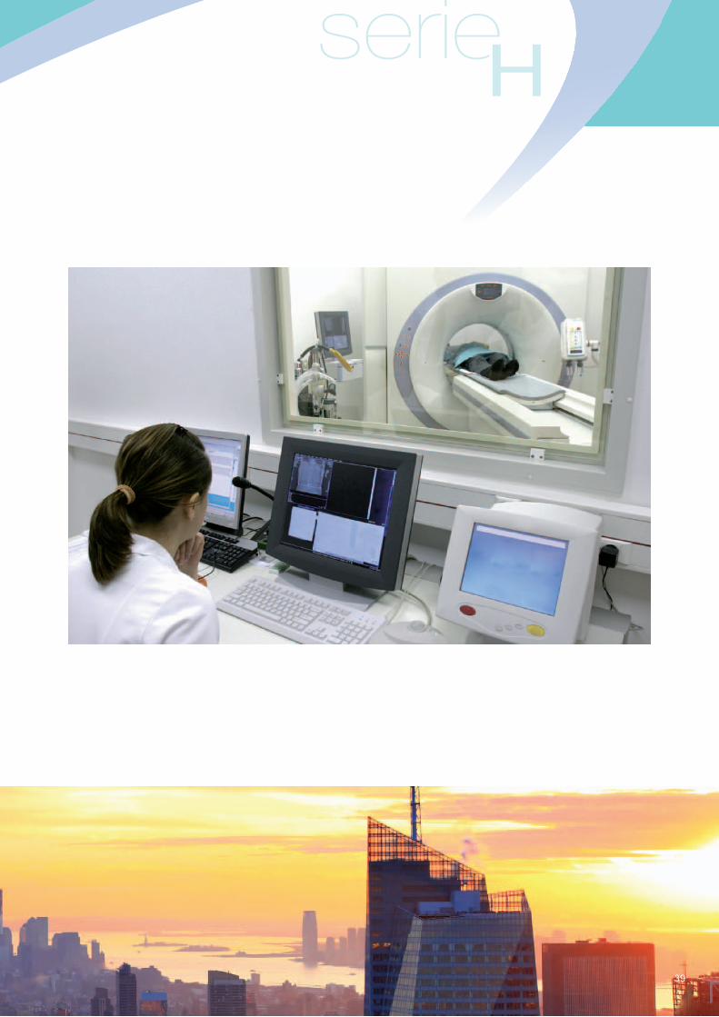
Plant for diagnostic imaging
General characteristics
The air conditioning plant for a magnetic
resonance department serves three separate
areas, all of which have quite different
characteristics and requirements:
1. Examination room
2. Control room
3. Technical room
1. Examination room
This is a volume of roughly 100-120 m3, without
araisedfloorandthereforewithairdistribution
from above. It is characterized by the presence
of the scanner and the consequent dissipation
of its heat, about 4 kW, and by its helium
charge for cooling the magnet. It is this helium
charge (about 100 kilos) which in the event of
any leakages could create severe respiratory
problems for the patient.
The characteristics of the air conditioning plant
for this room are as follows:
- supply airflow (full fresh air), approx. 10
volumes per hour, therefore about 1,200
m3/h.
- Air filtration: standard F7, maximum F9,
already guaranteed by the air conditioner, so
withoutfinalairfiltration.
- Exhaust airflow: approx. 1,000 m3/h, 60%
of which is from the magnet and the rest is
returned air expelled from the air conditioner;
- Ambient conditions: temperature 24°C ± 2°C;
humidity 50% ± 5%.
- Sensible cooling: approx. 5 kW.
- Emergency functioning (helium leakage):
an oxygen-quantity detector informs the air
conditioner’s microprocessor of any alarm
condition due to the probable escape of
helium. The microprocessor activates the
emergency software, sets off an acoustic and
visible alarm and doubles both the supply
and return/exhaust airflow in order to dilute
the presence of helium and to guarantee the
respiration of the patient and the health care
workers.
serieH
35
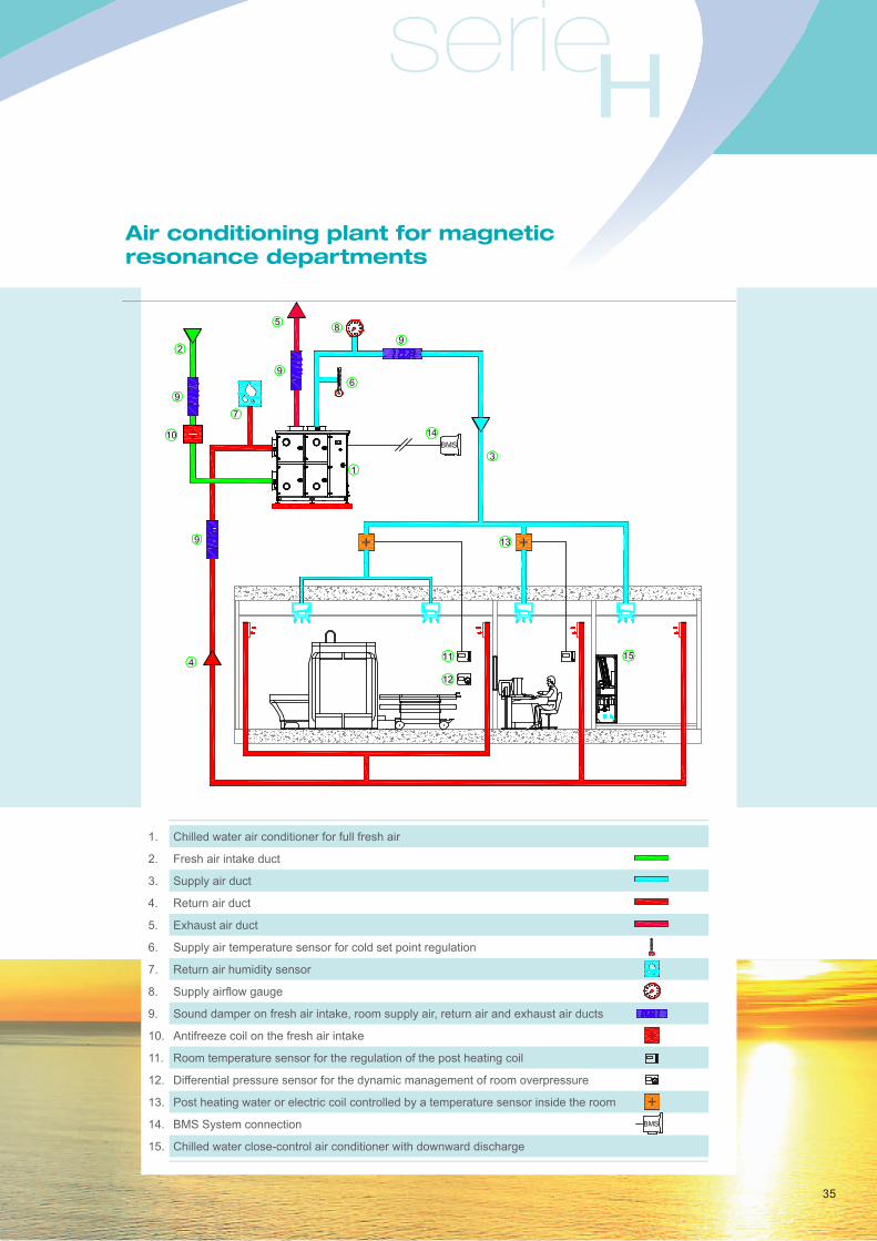
Air conditioning plant for magnetic resonance departments
1. Chilled water air conditioner for full fresh air
2. Fresh air intake duct
3. Supply air duct
4. Return air duct
5. Exhaust air duct
6. Supply air temperature sensor for cold set point regulation
7. Return air humidity sensor
8. Supplyairflowgauge
9. Sound damper on fresh air intake, room supply air, return air and exhaust air ducts
10. Antifreeze coil on the fresh air intake
11. Room temperature sensor for the regulation of the post heating coil
12. Differential pressure sensor for the dynamic management of room overpressure
13. Post heating water or electric coil controlled by a temperature sensor inside the room
14. BMS System connection
15. Chilled water close-control air conditioner with downward discharge

36
2. Control roomThis has a volume of approx. 70 m3.
Plant characteristics:
- supplyairflow(fullfreshair);6volumes/hour,
so about 450 m3/h;
- airfiltration:standardF7,maximumF9;
- exhaustairflow:about400m3/h;
- ambient conditions: temperature 22°C ± 2°C;
humidity: 50% ± 5%;
- sensible cooling: about 1.5 kW.
3. Technical roomThis has a volume of approx. 70 m3; it
normally has a raised floor and therefore the
air conditioner treating the recirculation air
discharges downwards.
Plant characteristics:
- supplyairflow(fullfreshair):2volumes/hour,
therefore about 150 m3/h;
- recirculationairflow:about4,000m3/h;
- airfiltration:F7,maximumF9forthefreshair;
G4 for the recirculation air;
- exhaustairflow:about50m3/h;
- ambient conditions: temperature 22°C ± 2°C;
humidity: 50% ± 5%;
- sensible cooling: about 20 kW.
serieH
37
Construction characteristics
1. PlantThe plant, which is normally completely
separate from the air conditioning system of the
hospital, uses full fresh air with integrated local
recirculation only in the machine room.
Temperature regulation is by set point with
the sensor in the supply compartment and the
humidity sensor in the return air compartment.
The constancy of the supply airflow is
guaranteed by a continuous measurement
device and correction by an inverter on the fan.
2. Air conditioner for fresh airAir conditioner for the treatment of full fresh
air, having the following characteristics, model
OHU2200:
- mono-block unit complete with controls,
electrical panel, microprocessor and
specializedsoftware,certifiedtoUNI/EN1886.
- The air conditioner normally has a chilled water
coil; direct expansion coil available as an
alternative.
- Normally without a heat recovery system, due
toboththelowairflowandtothefactthatpart
of the exhaust is done by the magnet and
therefore is not returned to the air conditioner.
- Motorised damper on the fresh air intake.
- G4freshairpre-filter.
- Hot water heating coil with microprocessor-
controlled three way valve functioning in mixing
and the related spill-back pump.
- Chilled water cooling coil with microprocessor-
controlled three way valve functioning in
deviation.
- Post-heating coil with microprocessor-
controlled three way valve functioning in
deviation.
- Modulating steam humidifier with immersed
electrodes controlled by microprocessor.
- Supply fan with electronic speed regulator and
airflowmeter.
- F7orF9efficiencysupplyairfilter.
- F5efficiencyreturnairfilter.
- Return/exhaust fan with inverter to regulate the
necessary room overpressure.
- RS485 board to connect to the remote control
system of the hospital.

38
3. Supply and return air ducting and accessoriesExternally insulated galvanized sheet metal,
airtight to at least class B:
- always fitted with a sound damper in the
supply and return air duct.
- The necessity of having sound dampers
installed in the fresh air intake and the
exhaust air outlet duct is dependent upon
the evaluation of the impact on the external
surrounding area.
- Post-heating coil on the supply duct to the
examination and control rooms; it is not
essential on the duct to the machine room
because that area always produces enough
heat itself; normally a hot water coil is used,
regulated by a three way modulating valve
which is controlled by a sensor installed in the
controlled room, alternatively an electric coil
with TRIAC regulation can be used.
4. Air conditioner for the machine roomChilled water with downward discharge of the
supplyair,modelUCU30.Thesupplyairflow
is regulated automatically as a function of the
power required by the electronic equipment.
A sensor in the air conditioner installed in
the return duct regulates the temperature.
Post-heating and humidification is not
necessary as these functions are already
guaranteed by the treatment of the fresh air.
serieH
39
40
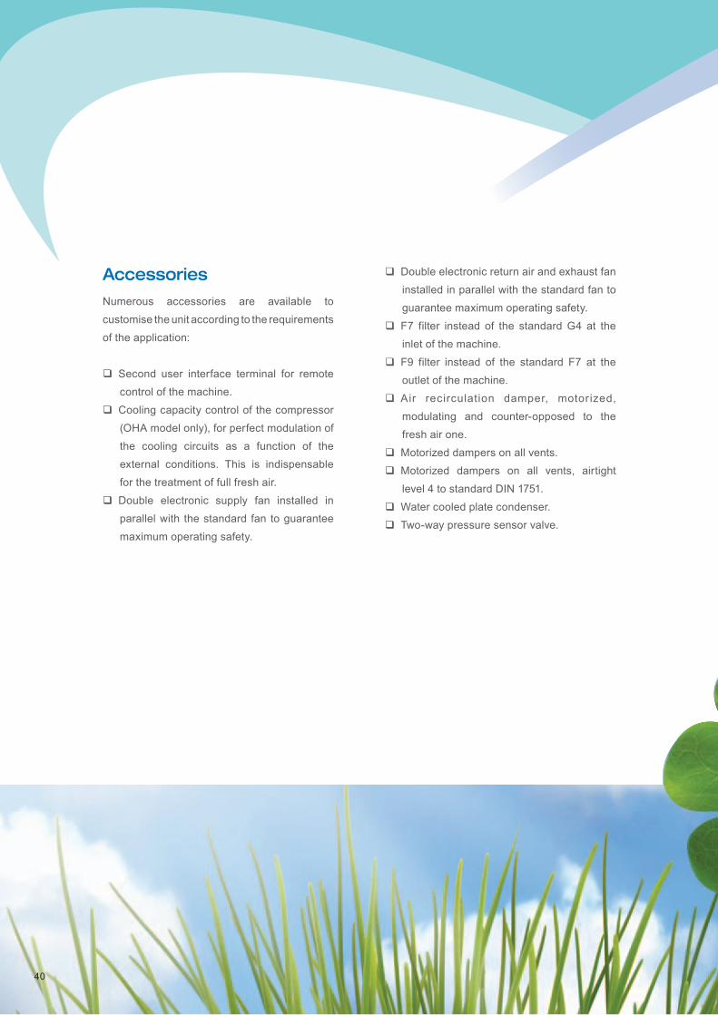
AccessoriesNumerous accessories are available to
customise the unit according to the requirements
of the application:
Second user interface terminal for remote
control of the machine.
Cooling capacity control of the compressor
(OHA model only), for perfect modulation of
the cooling circuits as a function of the
external conditions. This is indispensable
for the treatment of full fresh air.
Double electronic supply fan installed in
parallel with the standard fan to guarantee
maximum operating safety.
Double electronic return air and exhaust fan
installed in parallel with the standard fan to
guarantee maximum operating safety.
F7 filter instead of the standard G4 at the
inlet of the machine.
F9 filter instead of the standard F7 at the
outlet of the machine.
Air recirculation damper, motorized,
modulating and counter-opposed to the
fresh air one.
Motorized dampers on all vents.
Motorized dampers on all vents, airtight
level 4 to standard DIN 1751.
Water cooled plate condenser.
Two-way pressure sensor valve.

serieH
41
Temperature and humidity sensors supplied
loose instead of installed in the return
section.
Temperature sensor in the supply fan
section (cold point regulation) and humidity
sensor in the return section.
Pressure sensor to read the supply airflow
with constant pressure regulation.
Specific gateways for integration with
BACnet or Lonworks systems.
Specific gateways for remote management
via internet (TCP/IP) and via GSM modem
with SMS sending capability.
Hydronic heat recovery system.
Epoxy painted coil fins.
Direct expansion post-cooling system for
heart surgery.
Modulating centralized steam distributor
instead of an autonomous immersed-
electrode version.
Immersed resistance humidifier instead of
the immersed-electrode type.
Sealed internal lighting to enable correct-
function checks of the machine without
having to open it.
Water presence alarm.
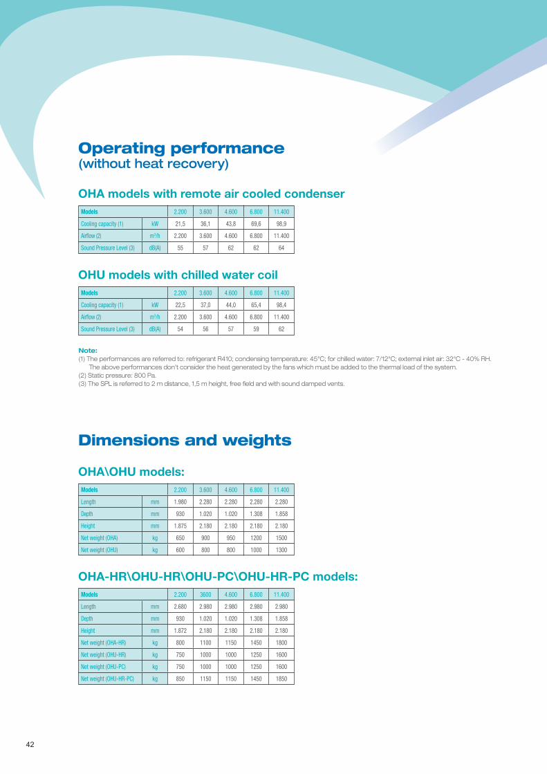
(without heat recovery)
OHA models with remote air cooled condenser
Operating performance
Dimensions and weights
42
Models 2.200 3.600 4.600 6.800 11.400
Cooling capacity (1) kW 21,5 36,1 43,8 69,6 98,9
Airflow (2) m3/h 2.200 3.600 4.600 6.800 11.400
Sound Pressure Level (3) dB(A) 55 57 62 62 64
OHU models with chilled water coilModels 2.200 3.600 4.600 6.800 11.400
Cooling capacity (1) kW 22,5 37,0 44,0 65,4 98,4
Airflow (2) m3/h 2.200 3.600 4.600 6.800 11.400
Sound Pressure Level (3) dB(A) 54 56 57 59 62
Note:(1) The performances are referred to: refrigerant R410; condensing temperature: 45°C; for chilled water: 7/12°C; external inlet air: 32°C - 40% RH. The above performances don’t consider the heat generated by the fans which must be added to the thermal load of the system.(2) Static pressure: 800 Pa.(3) The SPL is referred to 2 m distance, 1,5 m height, free field and with sound damped vents.
OHA\OHU models:Models 2.200 3.600 4.600 6.800 11.400
Length mm 1.980 2.280 2.280 2.280 2.280
Depth mm 930 1.020 1.020 1.308 1.858
Height mm 1.875 2.180 2.180 2.180 2.180
Net weight (OHA) kg 650 900 950 1200 1500
Net weight (OHU) kg 600 800 800 1000 1300
OHA-HR\OHU-HR\OHU-PC\OHU-HR-PC models: Models 2.200 3600 4.600 6.800 11.400
Length mm 2.680 2.980 2.980 2.980 2.980
Depth mm 930 1.020 1.020 1.308 1.858
Height mm 1.872 2.180 2.180 2.180 2.180
Net weight (OHA-HR) kg 800 1100 1150 1450 1800
Net weight (OHU-HR) kg 750 1000 1000 1250 1600
Net weight (OHU-PC) kg 750 1000 1000 1250 1600
Net weight (OHU-HR-PC) kg 850 1150 1150 1450 1850

TECNAIR LVCLOSE CONTROL AIR CONDITIONERS
serieH

AIR CONDITIONERSfor surgical rooms, hospital facilities and clean rooms
TECNAIR LVSURGICAL ROOM AIR CONDITIONING
ISO 9001Cert. n° 273GOST certification
TECNAIR LV S.p.A.
21040 Uboldo - Varese - ItalyVia Caduti della Liberazione, 53
Phone + 39 02.96.99.11.1Fax. + 39 02.96.78.15.70E-mail: [email protected]
www.tecnairlv.it
TECNAIR LVSURGICAL ROOM AIR CONDITIONING
7615
0207
C.0
413
TECNAIR LV has a policy of continuous development, so the company reserves the right to modify and improve any product described in this document without notice. Technical data and dimensions are not binding.