for the abb dpu2000r protection and control relay specification · 2018-05-10 · 5 . 1 feeder...
TRANSCRIPT

Replacement solution
for the ABB DPU2000R protection and control relay
Specification
File, Revision, Date (Pages)
Replacement Relay Specification_ABB DPU2000R_0.doc, Revision 0, August 2, 2013 (37)

2
Table of Contents 1 Feeder protection relay replacement ........................................................................... 5 2 General ........................................................................................................................ 5 3 Mechanical design and mounting ............................................................................... 6
3.1 Current connections.............................................................................................. 7 3.2 Control and status connections ............................................................................. 7 3.3 Communication and IRIG-B connections ............................................................ 7 3.4 Mounting .............................................................................................................. 7 3.5 Local Human Machine Interface (LHMI) ............................................................ 7
3.5.1 Circuit breaker control .................................................................................. 8 3.5.2 Indications and LEDs .................................................................................... 8 3.5.3 Embedded web server ................................................................................... 9 3.5.4 Local/Remote switch .................................................................................... 9
3.6 Inputs and outputs ................................................................................................ 9 3.6.1 Power supply input ....................................................................................... 9 3.6.2 Current input channels .................................................................................. 9 3.6.3 Voltage input channels ................................................................................ 10 3.6.4 Physical (binary) inputs and outputs ........................................................... 10 3.6.5 Self-supervision and alarm (IRF) output .................................................... 11 3.6.6 Master Trip function ................................................................................... 11
4 Protection .................................................................................................................. 12 4.1 Current protection .............................................................................................. 12
4.1.1 Non-directional phase time (51P) ............................................................... 12 4.1.2 Non-directional phase instantaneous (50P-1, 50P-2).................................. 13 4.1.3 Non-directional phase instantaneous, high-set (50P-3) .............................. 13 4.1.4 Non-directional neutral, ground time (51N, 51G) ...................................... 13 4.1.5 Non-directional neutral, ground instantaneous (50N/G-1, 50N/G-2) ......... 14 4.1.6 Non-directional neutral, ground instantaneous, high-set (50N-3, 50G-3) .. 14 4.1.7 Directional phase time (67/51P) ................................................................. 15 4.1.8 Directional phase instantaneous (67/50P-1, 67/50P-2) ............................... 15 4.1.9 Directional neutral time (67N) .................................................................... 16 4.1.10 Directional neutral instantaneous (67/50N-1, 67/50N-2) ........................... 17 4.1.11 Phase and neutral power directionals (32P/32N) ........................................ 17 4.1.12 Negative sequence time (46) ....................................................................... 17 4.1.13 Phase discontinuity (46PD) ........................................................................ 18 4.1.14 Thermal overload for feeder (49F) ............................................................. 18 4.1.15 Undercurrent (37)........................................................................................ 18 4.1.16 Cold load inrush (INR, 62CLD-1, 62CLD-2) ............................................. 19 4.1.17 Sensitive earth fault (SEF) .......................................................................... 19 4.1.18 Long time non-directional phase time (51LT) ............................................ 19
4.2 Voltage protection .............................................................................................. 20 4.2.1 Phase undervoltage (27) .............................................................................. 20 4.2.2 Phase overvoltage (59) ................................................................................ 20 4.2.3 Ground overvoltage (59G) .......................................................................... 21 4.2.4 Neutral overvoltage (59N) .......................................................................... 21

3
4.2.5 Negative sequence overvoltage (47) ........................................................... 21 4.3 Frequency protection .......................................................................................... 22
4.3.1 Load shed and restoration (81LSH) ............................................................ 22 4.3.2 Frequency (81) ............................................................................................ 22
4.4 Differential protection ........................................................................................ 23 4.4.1 Restricted earth fault, low impedance (87LOREF) .................................... 23
4.5 Other protections ................................................................................................ 23 4.5.1 Breaker-failure protection (50BF/50NBF) ................................................. 23 4.5.2 Overexcitation (24) ..................................................................................... 24 4.5.3 Arc flash detection (AFD) .......................................................................... 24 4.5.4 High impedance fault detection (HIZ) ........................................................ 25
4.6 Control ................................................................................................................ 25 4.6.1 Automatic reclosing .................................................................................... 25 4.6.2 Synchronism check (25) ............................................................................. 25
5 Measurements ........................................................................................................... 26 5.1 Phase currents ..................................................................................................... 26 5.2 Ground current ................................................................................................... 26 5.3 Current sequence components ............................................................................ 27 5.4 Phase voltages .................................................................................................... 27 5.5 Voltage sequence components ........................................................................... 27 5.6 Single- and three-phase power, energy and power factor .................................. 28 5.7 Frequency ........................................................................................................... 28
6 Records, load profile and time synchronization ....................................................... 28 6.1 Sequence of events (SOE) records ..................................................................... 29 6.2 Fault records ....................................................................................................... 29 6.3 Digital fault recorder (DFR) records .................................................................. 29 6.4 Load profile ........................................................................................................ 29 6.5 Time synchronization ......................................................................................... 30
7 Condition monitoring ................................................................................................ 30 7.1 Circuit breaker (52CM) ...................................................................................... 30 7.2 Self-supervision .................................................................................................. 30 7.3 Trip circuit monitoring (TCM) ........................................................................... 31 7.4 Current circuit monitoring (CCM) ..................................................................... 31 7.5 Fuse failure (60) ................................................................................................. 31 7.6 Power quality (PQ) ............................................................................................. 31 7.7 Cable fault detection (CFD) ............................................................................... 31 7.8 Fault location ...................................................................................................... 32
8 Communication interfaces ........................................................................................ 32 8.1 IEC61850 compliance and GOOSE messaging ................................................. 33 8.2 User authorization .............................................................................................. 33
9 Setting and configuration software ........................................................................... 33 10 Electrical and environmental conditions ................................................................... 33
10.1 Insulation compatibility .................................................................................. 33 10.2 Environmental conditions and tests ................................................................ 34
10.2.1 Environmental conditions ........................................................................... 34 10.2.2 Environmental tests ..................................................................................... 34

4
10.3 Electromagnetic compatibility ........................................................................ 34 10.4 Mechanical tests ............................................................................................. 36 10.5 EMC compliance ............................................................................................ 36
11 Quality assurance and standards ............................................................................... 36 12 Approved manufacture(s) and product(s) ................................................................. 37

5
1 Feeder protection relay replacement This specification is valid for applications where the following criteria are typically applicable: - An ABB DPU2000R is presently installed providing protection and control with
CT, VT, physical inputs, physical outputs and communication connections. - Feeder protection using directional phase and ground overcurrent, voltage and
frequency protection and power system metering for one breaker - Utility and industrial distribution systems that are solidly grounded, resistive
grounded or ungrounded and auto-reclosing is either necessary or unnecessary The specification highlights constructional features and software functions that are required within the specific relay application area. The specification applies to design, manufacture, supply, testing and operation of protection, measuring, control and recording functions intended for the quick and easy replacement of an installed ABB DPU2000R protection and control relay.
2 General The provided replacement relay shall fit in the same panel cutout and utilize the same mounting holes and hardware as the installed ABB DPU2000R relay. This requirement shall apply to panel- and rack-mounted DPU2000R units. The provided relay shall work reliably and selectively as part of a protection system. The relay must not operate at faults occurring outside the protection zone. Internal faults or disturbances in the auxiliary power supply or measurement circuits may not cause incorrect operation of the device. Each pickup or trip status provided by the relay must generate clear and reliable indications. These indications must be transferable to an upper level system over the substation communications network. The relay shall be of a microprocessor (numerical) communicating type design architecture offering extensive protection, control, measuring and recording functions in one enclosed unit. The protection relay basic design and data modeling shall be based on the IEC 61850 standard. The replacement relay shall include a similar programmable logic matrix though preference is to have the ability to program protection and control logic through a graphical user interface. The relay shall have full flexibility in terms of assigning any binary input (BI) or binary output (BO) signal to the internal logic circuits.

6
The following specification highlights the most important relay features and functions required. The relay must comply with the relevant ANSI and IEC standards and be suitable for the intended applications, as described in the complete set of specifications, or otherwise communicated to the prospective Bidders. Relay firmware must be compliant to IEC61850-8-1 standard regardless of communication option selections. Relay must include a clock feature that maintains the current date and time for proper stamping of recorded events for critical post-fault or post-alarm review and analysis. Relay clock feature technology must be battery-free and maintain date and time during short power supply outages not lasting longer than 48 hours. Preference is for the product(s) that comply with this project’s specification requirements to be part of the same family of products that share one common user tool, interoperability per IEC 61850-8-1 standard, similar local human machine interface (LHMI) language and liquid crystal display (LCD) menu navigation and design technologies. The replacement relay shall be capable of operation for 50 Hz or 60 Hz power system via a user selectable setting, i.e., support for these two power systems shall not require a different ordering code.
3 Mechanical design and mounting The relay design shall include a "draw-out” component where the draw-out unit can be withdrawn from or inserted to a fixed mounted housing. The withdrawal of the draw-out unit shall maintain the integrity of the wired current transformer (CT) secondary circuits. It shall be possible to safely extract the draw-out unit from the case (base unit) after disconnecting the control voltage without adding any external jumper wires or operating any additional switches or bridges. Means shall be included to seal the draw-out unit into the base unit, to prevent accidental removal. Connections All current, voltage and binary input and output connections shall be of the ring-lug screw terminal type; not compression terminal type. Compression terminals are acceptable for communication and time synchronization, e.g., RS-485 and IRIG-B connections, respectively. The replacement relay design shall be wire-alike for all equivalent CT, VT and physical input and output terminal connections to within 0.25” of their present x-y-z coordinates of the original installation.
7
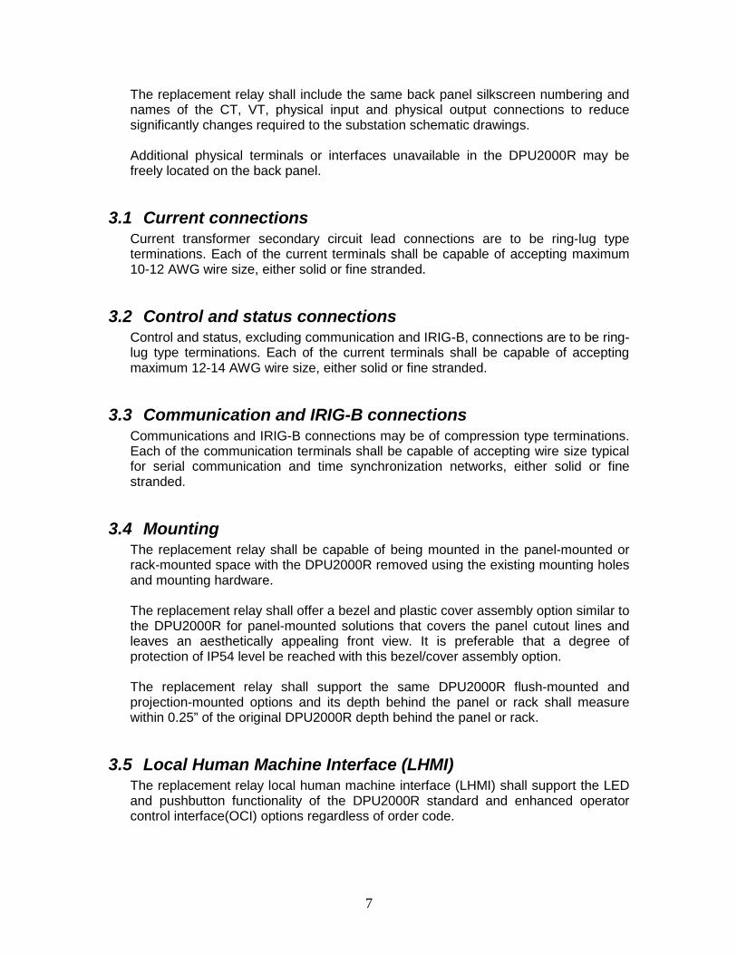
The replacement relay shall include the same back panel silkscreen numbering and names of the CT, VT, physical input and physical output connections to reduce significantly changes required to the substation schematic drawings. Additional physical terminals or interfaces unavailable in the DPU2000R may be freely located on the back panel.
3.1 Current connections Current transformer secondary circuit lead connections are to be ring-lug type terminations. Each of the current terminals shall be capable of accepting maximum 10-12 AWG wire size, either solid or fine stranded.
3.2 Control and status connections Control and status, excluding communication and IRIG-B, connections are to be ring-lug type terminations. Each of the current terminals shall be capable of accepting maximum 12-14 AWG wire size, either solid or fine stranded.
3.3 Communication and IRIG-B connections Communications and IRIG-B connections may be of compression type terminations. Each of the communication terminals shall be capable of accepting wire size typical for serial communication and time synchronization networks, either solid or fine stranded.
3.4 Mounting The replacement relay shall be capable of being mounted in the panel-mounted or rack-mounted space with the DPU2000R removed using the existing mounting holes and mounting hardware. The replacement relay shall offer a bezel and plastic cover assembly option similar to the DPU2000R for panel-mounted solutions that covers the panel cutout lines and leaves an aesthetically appealing front view. It is preferable that a degree of protection of IP54 level be reached with this bezel/cover assembly option. The replacement relay shall support the same DPU2000R flush-mounted and projection-mounted options and its depth behind the panel or rack shall measure within 0.25” of the original DPU2000R depth behind the panel or rack.
3.5 Local Human Machine Interface (LHMI) The replacement relay local human machine interface (LHMI) shall support the LED and pushbutton functionality of the DPU2000R standard and enhanced operator control interface(OCI) options regardless of order code.

8
The replacement relay shall support via order code option an ANSI or IEC language version similar to the DPU2000R order code option. The replacement relay LHMI shall support a freely programmable liquid crystal display (LCD) as part of the LHMI where user may develop their own display of measurement values, text strings and a single line diagram (SLD) including a controllable object to operate, e.g., a breaker. The LHMI shall support local measurement, event and alarm views through its LCD display. The LHMI shall provide access to view and, with proper password authorization, edit protection settings. The LHMI shall support choosing either an SLD, main menu or metering view as the default LCD view. The LHMI LCD is to be fitted with minimum 10 rows and 20 characters per row with legible font size and backlight. The backlight shall have a user selectable timeout setting which will automatically turn off the light after the set time expires. When the backlight is off, it should automatically turn on upon the pressing of an LHMI button. LHMI must include an RJ45 Ethernet communications port with static IP for local interfacing via the web browser or relay’s user software tool. The LHMI shall provide menu navigation keys for viewing and editing activities.
3.5.1 Circuit breaker control It shall be possible to perform a circuit breaker control from designated control buttons on the replacement relay LHMI. It shall be possible to interlock the circuit breaker close command directly by a binary input, by a protection relay internal interlocking logic, by a thermal protection operation or by a protection relay trip command output operating in lockout mode.
3.5.2 Indications and LEDs Each pickup and trip event from each protection function must be clearly indicated. It must also be possible to transfer the pickup and trip signals to available physical outputs if required and to transfer the signals to an upper level system via all of its available communication Ethernet and serial interfaces and IEC-61850 and communication protocols. The resetting of indications and alarm LEDs shall be easy from the LHMI using minimum number of navigation pushbuttons. The replacement relay LHMI shall support at least eleven (11) freely programmable alarm LEDs for status indication and an LED per available freely programmable pushbutton. It shall be possible to remove the factory default LED description sheet and replace with a user-defined description sheet.

9
3.5.3 Embedded web server The relay shall be equipped with web server functionality for local or remote access to view LHMI LED status, view and edit settings, perform controls, and retrieve records and digital fault recording (DFR) data using commonly available web browser software such as Microsoft’s Internet Explorer and Mozilla Firefox. The web server functionality shall utilize the same user authorization principles, defined later in this specification, as the LHMI authorization. Activation of the web server shall need user intervention, thus the functionality shall be disabled as a default.
3.5.4 Local/Remote switch The LHMI shall be equipped with a Local/Remote (L/R) switch including status indication. The operation rights of the L/R switch shall be covered with the user authorization principles of the relay. When in local mode, remote control commands to the circuit breaker shall be ignored and vice versa in remote mode.
3.6 Inputs and outputs The relay shall include these input and output requirements:
3.6.1 Power supply input Description Value Power supply (nominal), Vn: Type 1: 48/60/110/125/220/250 V DC, 50/60 Hz
Type 2: 24/30/48/60 V DC
3.6.2 Current input channels The replacement relay shall provide the same number current inputs as in the DPU2000R based on order code selection. These current inputs must be located and named as they are in the DPU2000R based on order code selection. The same relay hardware shall support both 5 A and 1 A nominal current transformer (CT) secondary ratings for the phase and ground CT analog input channels. Separate phase and ground CT secondary nominal ratings shall be available and their selections shall be made via software settings. All the CT analog input channels shall have dedicated analog-to-digital (A/D) converters to enable simultaneous sampling and eliminate skew. The A/D conversion shall be of such design that good linearity during the lifetime of the relay can be achieved. The analog signals shall be presented to the relay’s internal function blocks at a sampling rate of no less than 32 samples per cycle with an 18-bit resolution and signal to quantization noise ratio (SQNR) better than 110 db. The phase and ground CT analog input channels shall meet these minimum ratings for 50/60 Hz: Description Value

10
Rated (nominal) current, In: 5 A or 1 A, user programmable Thermal withstand, continuous: 20 A Thermal withstand, 1 s: 500 A Dynamic withstand, half-wave: 1250 A Burden: < 20 mΩ The (optional) SEF/HIZ analog input channel shall meet these minimum ratings for 50/60 Hz: Description Value Rated (nominal) current, In: 0.2 A Thermal withstand, continuous: 4 A Thermal withstand, 1 s: 100 A Dynamic withstand, half-wave: 250 A Burden: < 100 mΩ
3.6.3 Voltage input channels The replacement relay shall provide at least five (5) voltage inputs to support three-phase bus VT, synchronism check VT and zero sequence voltage VT voltage inputs. These voltage inputs must be located and named as they are in the DPU2000R based on order code selection. The additional voltage input should be located near and named similarly to the other voltage inputs. The same relay hardware shall support nominal voltage transformer (VT) secondary ratings from 60 to 210 V AC. A phase VT secondary nominal rating shall be available and its selection shall be made via software settings. All the VT analog input channels shall have dedicated analog-to-digital (A/D) converters to enable simultaneously sampling and elimination of skew. A/D digital conversion shall be of such design that good linearity during the whole lifetime of the relay can be achieved. The analog signals shall be presented to the protection relay internal function blocks as no less than 32 samples-per-cycle with 18 bit resolution with a signal to quantization noise ratio (NQSR) better than 110 db. The VT analog input channels shall meet these minimum ratings for 50/60 Hz: Description Value Rated (nominal) voltage, Vn: 60…210 V AC , user programmable Withstand continuous: 2 x Vn (240 V AC maximum) Withstand for 10 s: 3 x Vn (360 V AC maximum) Burden at Vn: < 0.05 VA The relay must support both phase-to-phase and phase-to-neutral voltage VT input connections.
3.6.4 Physical (binary) inputs and outputs The replacement relay shall provide the same exact number of inputs, assigned screw terminals and back panel silkscreen description as in the DPU2000R. The relay shall be delivered with a default logic configuration which matches much of the

11
internal DPU2000R logic, e.g., Cold-load pickup, breaker failure, overcurrent pickup alarm, etc. It shall be possible via software to freely assign the physical inputs and outputs to the protection relay internal function logic. A possibility to introduce simple logic functions in the form of AND and OR gates, including signal inversion, in front of the binary inputs and outputs shall also be available. As an example, a possibility to energize a physical output from a number of internal relay signals (OR gate) shall be available. The turn-on threshold voltage of the binary inputs shall be settable using a dedicated parameter. The inputs shall meet these minimum ratings: Description Value Operating range: ±20 % of the nominal voltage Nominal voltage: 24...250 VDC Threshold voltage: 18...175 VDC Reaction time: <5 ms The replacement relay shall provide the same exact number of outputs, assigned screw terminals and back panel silkscreen description as in the DPU2000R. The TRIP and CLOSE binary outputs shall be of a heavy-duty type, i.e., a power output, capable of tripping a circuit breaker per these output contact ratings: Description Value Rated voltage: 250 V DC/AC Continuous contact carry: 8 A Make and carry for 3.0 s: 15 A Make and carry for 0.5 s: 30 A Breaking capacity at 48/110/220 V DC at L/R = 40 ms: 5 A/3 A/1 A
3.6.5 Self-supervision and alarm (IRF) output The replacement relay shall include a Normally Closed (NC) and Normally Open (NO) output contact dedicated as a self-check failure or Internal Relay Fault (IRF) alarm to provide relay self-check status to external systems. The relay shall be equipped with extensive self-supervision capabilities. In case of an internal failure, the relay shall disable protection to prevent a false trip and activate the alarm output. The failure code shall be visible on the protection relay LHMI display. The failure codes shall give detailed information about the situation. The end user documentation shall support the interpretation of the failure code in detail and by simple means.
3.6.6 Master Trip function Programmable master trip logic shall be available for use on two output contacts. The logic shall include a selectable lock-out operation mode which locks or seals-in the output contact after operation. The resetting of the lock-out state shall be possible via the LHMI, a physical (binary) input and the communication interface. If

12
required, it shall be possible to disable the master trip logic and the outputs it drives by means of a user-programmable setting.
4 Protection The replacement relay must have at least three (3) setting groups for each of the protection functions as in the DPU2000R though support for six (6) different setting groups is preferred. It shall be possible to change the setting group locally from the LHMI, using a binary input signal and remotely through the communication port interfaces. The change of setting group shall happen rapidly and it shall not result in a protection relay restart, a relay malfunction or a communication break. The protection functions listed below shall be regarded as the minimum required basic protection features. The list of functions exceeds those in the DPU2000R making it more capable than the relay it replaces for future protection needs. It shall be possible to either enable or disable each protection element, depending on the requirements of the actual application.
4.1 Current protection
4.1.1 Non-directional phase time (51P) The protection shall consist of a freely programmable non-directional phase time overcurrent protective function with at least these setting options: Setting description Setting range, step size Measurement mode: DFT (fundamental), RMS or Peak-to-Peak Pickup: 0.05 – 5.00 x In, step 0.01 x In Curve: ANSI, IEC, Definite time and User Programmable
curves Time multiplier: 0.05 – 15.00, step 0.05 Definite time delay: 0.04 – 200 seconds, step 0.01 seconds Curve reset mode: Immediate, inverse or definite time The function shall include a setting that automatically raises the pickup setting by a user-defined multiplying factor whenever enabled by logic. It shall be possible to select the minimum number of phases, one, two or three, that must exceed the pickup setting for the function to issue a trip. The function shall include digital input logic programmable for control purposes, e.g., blocking, and digital output logic programmable to the physical outputs and other programming logic.

13
4.1.2 Non-directional phase instantaneous (50P-1, 50P-2) The protection shall consist of at least two freely programmable non-directional phase instantaneous overcurrent functions for use as low-set and mid-set instantaneous protection with at least these setting options: Setting description Setting range, step size Measurement mode: DFT, RMS or Peak-to-Peak Pickup: 0.10 – 40.00 x In, step 0.01 x In Curve: ANSI, IEC, Definite time and User Programmable
curves Time delay: 0.04 – 200 seconds, step 0.01 seconds The function shall include a setting that automatically raises the pickup setting by a user-defined multiplying factor whenever enabled by logic. It shall be possible to select the minimum number of phases, one, two or three, that must exceed the pickup setting for the function to issue a trip. The function shall include digital input logic programmable for control purposes, e.g., blocking, and digital output logic programmable to the physical outputs and other programming logic.
4.1.3 Non-directional phase instantaneous, high-set (50P-3) The protection shall consist of a freely programmable non-directional phase high-set instantaneous overcurrent protective function with at least these setting options: Setting description Setting range, step size Measurement mode: Peak-to-Peak Pickup: 1.00 – 40.00 x In, step 0.01 x In Curve: Definite time Time delay: 0.02 – 200 seconds, step 0.01 seconds The function shall include a setting that automatically raises the pickup setting by a user-defined multiplying factor whenever enabled by logic. It shall be possible to select the minimum number of phases, one, two or three, that must exceed the pickup setting for the function to issue a trip. The function shall include digital input logic programmable for control purposes, e.g., blocking, and digital output logic programmable to the physical outputs and other programming logic.
4.1.4 Non-directional neutral, ground time (51N, 51G) The protection shall consist of freely programmable non-directional neutral and, depending on the order code selection, ground time overcurrent protective functions. The neutral function shall use a zero sequence current value calculated from the three-phase CT inputs. The ground function shall use a zero sequence current value measured from the ground CT input, when ordered. The functions shall have at least these setting options: Setting description Setting range, step size Measurement mode: DFT (fundamental), RMS or Peak-to-Peak

14
Pickup: 0.01 – 5.00 x In, step 0.005 x In Curve: ANSI, IEC, Definite time and User Programmable
curves Time multiplier: 0.05 – 15.00, step 0.05 Definite time delay: 0.04 – 200 seconds, step 0.01 seconds The function shall include a setting that automatically raises the pickup setting by a user-defined multiplying factor whenever enabled by logic. The function shall include digital input logic programmable for control purposes, e.g., blocking, and digital output logic programmable to the physical outputs and other programming logic.
4.1.5 Non-directional neutral, ground instantaneous (50N/G-1, 50N/G-2) The protection shall consist of at least two freely programmable non-directional neutral and, depending on the order code selection, ground instantaneous overcurrent functions for use as low-set and mid-set instantaneous protection. The neutral function shall use a zero sequence current value calculated from the three-phase CT inputs. The ground function shall use a zero sequence current value measured from the ground CT input, when ordered. The functions shall have at least these setting options: Setting description Setting range, step size Measurement mode: DFT, RMS or Peak-to-Peak Pickup: 0.10 – 40.00 x In, step 0.01 x In Curve: ANSI, IEC, Definite time and User Programmable
curves Time delay: 0.04 – 200 seconds, step 0.01 seconds The function shall include a setting that automatically raises the pickup setting by a user-defined multiplying factor whenever enabled by logic. The function shall include digital input logic programmable for control purposes, e.g., blocking, and digital output logic programmable to the physical outputs and other programming logic.
4.1.6 Non-directional neutral, ground instantaneous, high-set (50N-3, 50G-3)
The protection shall consist of freely programmable non-directional neutral and, depending on the order code selection, ground high-set instantaneous overcurrent protective functions. The neutral function shall use a zero sequence current value calculated from the three-phase CT inputs. The ground function shall use a zero sequence current value measured from the ground CT input, when ordered. The functions shall have at least these setting options: Setting description Setting range, step size Measurement mode: Peak-to-Peak Pickup: 1.00 – 40.00 x In, step 0.01 x In Curve: Definite time Time delay: 0.02 – 200 seconds, step 0.01 seconds

15
The function shall include a setting that automatically raises the pickup setting by a user-defined multiplying factor whenever enabled by logic. The function shall include digital input logic programmable for control purposes, e.g., blocking, and digital output logic programmable to the physical outputs and other programming logic.
4.1.7 Directional phase time (67/51P) The protection shall consist of a freely programmable directional phase time overcurrent protective function. The function shall support user-programmable minimum operate current and voltage settings for secure and sensitive operation. It shall be possible to apply this function as a non-directional element with software settings. The element shall support at least these setting options: Setting description Setting range, step size Direction mode: Forward, Reverse or Non-directional Polarization mode: Positive sequence voltage, Negative sequence
voltage, Self-polarization or Cross-polarization Maximum torque angle: -179 – +180 degrees, step 1 degree Forward sector width: 0 – 180 degrees, step 1 degree, asymmetrical Reverse sector width: 0 – 180 degrees, step 1 degree, asymmetrical Measurement mode: DFT (fundamental), RMS or Peak-to-Peak Pickup: 0.05 – 5.00 x In, step 0.01 x In Curve: ANSI, IEC, Definite time and User Programmable
curves Time multiplier: 0.05 – 15.00, step 0.05 Definite time delay: 0.06 – 200 seconds, step 0.01 seconds Curve reset mode: Immediate, inverse or definite time The function shall include a setting that automatically raises the pickup setting by a user-defined multiplying factor whenever enabled by logic. It shall be possible to select the minimum number of phases, one, two or three, that must exceed the pickup setting for the function to issue a trip. The function shall include digital input logic programmable for control purposes, e.g., blocking, and digital output logic programmable to the physical outputs and other programming logic.
4.1.8 Directional phase instantaneous (67/50P-1, 67/50P-2) The protection shall consist of at least two freely programmable directional phase instantaneous overcurrent functions for use as low-set and high-set directional instantaneous protection. The function shall support user-programmable minimum operate current and voltage settings for secure and sensitive operation. It shall be possible to apply this function as a non-directional element with software settings. The function shall support at least these setting options: Setting description Setting range, step size Direction mode: Forward, Reverse or Non-directional

16
Polarization mode: Positive sequence voltage, Negative sequence voltage, Self-polarization or Cross-polarization
Maximum torque angle: -179 – +180 degrees, step 1 degree Forward sector width: 0 – 180 degrees, step 1 degree, asymmetrical Reverse sector width: 0 – 180 degrees, step 1 degree, asymmetrical Measurement mode: DFT (fundamental), RMS or Peak-to-Peak Pickup: 0.10 – 40.00 x In, step 0.01 x In Curve: ANSI, IEC, Definite time and User Programmable
curves Time multiplier: 0.05 – 15.00, step 0.05 Definite time delay: 0.04 – 200 seconds, step 0.01 seconds Curve reset mode: Immediate, inverse or definite time The function shall include a setting that automatically raises the pickup setting by a user-defined multiplying factor whenever enabled by logic. It shall be possible to select the minimum number of phases, one, two or three, that must exceed the pickup setting for the function to issue a trip. The function shall include digital input logic programmable for control purposes, e.g., blocking, and digital output logic programmable to the physical outputs and other programming logic.
4.1.9 Directional neutral time (67N) The protection shall consist of a freely programmable directional neutral time overcurrent protective function. The protection shall support user selection of a zero sequence current value measured from the ground CT input or calculated from the three-phase CT inputs. The function shall support user-programmable minimum operate current and voltage settings for secure and sensitive operation. It shall be possible to apply this function as a non-directional element with software settings. The function shall support at least these setting options: Setting description Setting range, step size Direction mode: Forward, Reverse or Non-directional Polarization mode: Negative sequence voltage, Measured 3V0,
Calculated 3V0 Maximum torque angle: -179 – +180 degrees, step 1 degree Forward sector width: 0 – 180 degrees, step 1 degree, asymmetrical Reverse sector width: 0 – 180 degrees, step 1 degree, asymmetrical Measurement mode: DFT (fundamental), RMS or Peak-to-Peak Pickup: 0.010 – 5.000 x In, step 0.005 x In Curve: ANSI, IEC, Definite time and User Programmable
curves Time multiplier: 0.05 – 15.00, step 0.05 Definite time delay: 0.04 – 200 seconds, step 0.01 seconds Curve reset mode: Immediate, inverse or definite time The function shall include a setting that automatically raises the pickup setting by a user-defined multiplying factor whenever enabled by logic.

17
The function shall include digital input logic programmable for control purposes, e.g., blocking, and digital output logic programmable to the physical outputs and other programming logic.
4.1.10 Directional neutral instantaneous (67/50N-1, 67/50N-2) The protection shall consist of at least two freely programmable directional phase time overcurrent functions for use as low-set and high-set directional instantaneous protection. The protection shall support user selection of a zero sequence current value measured from the ground CT input or calculated from the three-phase CT inputs. The function shall support user-programmable minimum operate current and voltage settings for secure and sensitive operation. It shall be possible to apply this function as a non-directional element with software settings. The function shall support at least these setting options: Setting description Setting range, step size Direction mode: Forward, Reverse or Non-directional Polarization mode: Negative sequence voltage, Measured 3V0,
Calculated 3V0 Maximum torque angle: -179 – +180 degrees, step 1 degree Forward sector width: 0 – 180 degrees, step 1 degree, asymmetrical Reverse sector width: 0 – 180 degrees, step 1 degree, asymmetrical Measurement mode: DFT (fundamental), RMS or Peak-to-Peak Pickup: 0.10 – 40.00 x In, step 0.01 x In Curve: ANSI, IEC, Definite time and User Programmable
curves Time multiplier: 0.05 – 15.00, step 0.05 Definite time delay: 0.04 – 200 seconds, step 0.01 seconds Curve reset mode: Immediate, inverse or definite time The function shall include a setting that automatically raises the pickup setting by a user-defined multiplying factor whenever enabled by logic. The function shall include digital input logic programmable for control purposes, e.g., blocking, and digital output logic programmable to the physical outputs and other programming logic.
4.1.11 Phase and neutral power directionals (32P/32N) The protection shall consist of freely programmable phase and neutral power directional elements for sensitive and high-speed power direction indication for islanding needs between utility system and local generation.
4.1.12 Negative sequence time (46) The protection shall include at least two freely programmable negative sequence time overcurrent protective functions. The function shall use a negative sequence current value calculated from the three-phase CT inputs. The functions shall have at least these setting options: Setting description Setting range, step size Pickup: 0.01 – 5.00 x In, step 0.01 x In

18
Curve: ANSI, IEC, Definite time and User Programmable curves
Time multiplier: 0.05 – 15.00, step 0.05 Definite time delay: 0.04 – 200 seconds, step 0.01 seconds The function shall include a setting that automatically raises the pickup setting by a user-defined multiplying factor whenever enabled by logic. The function shall include digital input logic programmable for control purposes, e.g., blocking, and digital output logic programmable to the physical outputs and other programming logic.
4.1.13 Phase discontinuity (46PD) The protection shall include a freely programmable phase discontinuity protective function. The function shall determine the extent of the phase unbalance by calculating the ratio of the negative sequence current to the positive sequence current calculated from the three-phase CT inputs. The function shall have at least these setting options: Setting description Setting range, step size Minimum phase current: 0.05 – 0.30 x In, step 0.01 x In Pickup: 10 – 100 % I2/I11, step 1 % Curve: Definite time Definite time delay: 0.10 – 30 seconds, step 0.001 seconds The function shall include digital input logic programmable for control purposes, e.g., blocking, and digital output logic programmable to the physical outputs and other programming logic.
4.1.14 Thermal overload for feeder (49F) The protection shall consist of freely programmable feeder thermal overload protective function. The function shall estimate feeder cable thermal value calculated from the three-phase CT inputs. The function shall have these setting options: Setting description Setting range, step size Ambient temperature: -50 - +100 °C, step 1 °C Current reference: 0.05 – 4.00 x In, step 0.01 x In Time constant: 60 – 60000, step 1 second Alarm temperature: 20 – 150 °C, step 0.1 °C Maximum temperature: 20 – 200 °C, step 0.1 °C Reclose block temperature: 20 – 150 °C, step 0.1 °C The function shall include digital input logic programmable for control purposes, e.g., blocking, and digital output logic programmable to the physical outputs and other programming logic.
4.1.15 Undercurrent (37) The protection shall consist of a freely programmable undercurrent protective function. The function shall monitor all three phase currents measured from the three-phase CT inputs. The functions shall have at least these setting options:

19
Setting description Setting range, step size Operation mode: Single-phase or Three-phase Low pickup: 0.00 – 0.50 x In, step 0.01 x In High pickup: 0.01 – 1.00 x In, step 0.01 x In Definite time delay: 0.05 – 200 seconds, step 0.01 seconds The function shall include digital input logic programmable for control purposes, e.g., blocking, and digital output logic programmable to the physical outputs and other programming logic.
4.1.16 Cold load inrush (INR, 62CLD-1, 62CLD-2) The protection shall consist of an inrush detector and two freely programmable timers for preventing unwanted trips upon a breaker closing into a cold feeder load. The function shall support at least these setting options: Setting description Setting range, step size Inrush pickup: 0.05 – 1.00 x In, step 0.01 x In Cold load timer #1: 0 – 300 seconds, step 1 second Cold load timer #2: 0 – 300 minutes, step 1 minute The function shall include digital input logic programmable for control purposes, e.g., blocking, and digital output logic programmable to the physical outputs and other programming logic.
4.1.17 Sensitive earth fault (SEF) The relay shall provide for ordering optional SEF protection for use in ungrounded distribution systems or grounded distribution systems with the loads connected line-to-line. The protection shall be a freely programmable function. The SEF function shall use a measured zero sequence current value from the ground CT input when ordered. The functions shall have at least these setting options: Setting description Setting range, step size Measurement mode: DFT (fundamental), RMS or Peak-to-Peak Pickup: 0.01 – 5.00 x In, step 0.005 x In Curve: ANSI, IEC, Definite time and User Programmable
curves Time multiplier: 0.05 – 15.00, step 0.05 Definite time delay: 0.04 – 200 seconds, step 0.01 seconds The function shall include a setting that automatically raises the pickup setting by a user-defined multiplying factor whenever enabled by logic. The function shall include digital input logic programmable for control purposes, e.g., blocking, and digital output logic programmable to the physical outputs and other programming logic.
4.1.18 Long time non-directional phase time (51LT) The protection shall consist of a freely programmable long time non-directional phase time overcurrent protective function with at least these setting options:
20
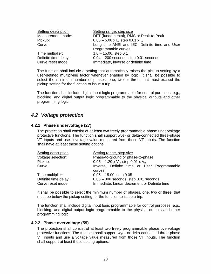
Setting description Setting range, step size Measurement mode: DFT (fundamental), RMS or Peak-to-Peak Pickup: 0.05 – 5.00 x In, step 0.01 x In Curve: Long time ANSI and IEC, Definite time and User
Programmable curves Time multiplier: 1.0 – 15.00, step 0.1 Definite time delay: 0.04 – 200 seconds, step 0.01 seconds Curve reset mode: Immediate, inverse or definite time The function shall include a setting that automatically raises the pickup setting by a user-defined multiplying factor whenever enabled by logic. It shall be possible to select the minimum number of phases, one, two or three, that must exceed the pickup setting for the function to issue a trip. The function shall include digital input logic programmable for control purposes, e.g., blocking, and digital output logic programmable to the physical outputs and other programming logic.
4.2 Voltage protection
4.2.1 Phase undervoltage (27) The protection shall consist of at least two freely programmable phase undervoltage protective functions. The function shall support wye- or delta-connected three-phase VT inputs and use a voltage value measured from those VT inputs. The function shall have at least these setting options: Setting description Setting range, step size Voltage selection: Phase-to-ground or phase-to-phase Pickup: 0.05 – 1.20 x Vn, step 0.01 x Vn Curve: Inverse, Definite time or User Programmable
curves Time multiplier: 0.05 – 15.00, step 0.05 Definite time delay: 0.06 – 300 seconds, step 0.01 seconds Curve reset mode: Immediate, Linear decrement or Definite time It shall be possible to select the minimum number of phases, one, two or three, that must be below the pickup setting for the function to issue a trip. The function shall include digital input logic programmable for control purposes, e.g., blocking, and digital output logic programmable to the physical outputs and other programming logic.
4.2.2 Phase overvoltage (59) The protection shall consist of at least two freely programmable phase overvoltage protective functions. The function shall support wye- or delta-connected three-phase VT inputs and use a voltage value measured from those VT inputs. The function shall support at least these setting options:

21
Setting description Setting range, step size Voltage selection: Phase-to-ground or phase-to-phase Pickup: 0.05 – 1.60 x Vn, step 0.01 x Vn Curve: Inverse, Definite time or User Programmable
curves Time multiplier: 0.05 – 15.00, step 0.05 Definite time delay: 0.04 – 300 seconds, step 0.01 seconds Curve reset mode: Immediate, Linear decrement or definite time It shall be possible to select the minimum number of phases, one, two or three, that must be above the pickup setting for the function to issue a trip. The function shall include digital input logic programmable for control purposes, e.g., blocking, and digital output logic programmable to the physical outputs and other programming logic.
4.2.3 Ground overvoltage (59G) The protection shall consist of a freely programmable ground overvoltage protective function. The function shall use a zero sequence voltage value measured from a dedicated VT input. The function shall support at least these setting options: Setting description Setting range, step size Pickup: 0.010 – 1.000 x Vn, step 0.001 x Vn Curve: Definite time Definite time delay: 0.040 – 300 seconds, step 0.001 seconds The function shall include digital input logic programmable for control purposes, e.g., blocking, and digital output logic programmable to the physical outputs and other programming logic.
4.2.4 Neutral overvoltage (59N) The protection shall consist of a freely programmable neutral overvoltage protective function. The function shall use a zero sequence voltage value calculated from wye-connected three-phase VT inputs. The function shall support at least these setting options: Setting description Setting range, step size Pickup: 0.010 – 1.000 x Vn, step 0.001 x Vn Curve: Definite time Definite time delay: 0.040 – 300 seconds, step 0.001 seconds The function shall include digital input logic programmable for control purposes, e.g., blocking, and digital output logic programmable to the physical outputs and other programming logic.
4.2.5 Negative sequence overvoltage (47) The protection shall consist of at least two freely programmable negative sequence overvoltage protective functions. The function shall use a negative sequence voltage value calculated from the three-phase VT inputs. The function shall support at least these setting options:

22
Setting description Setting range, step size Pickup: 0.010 – 1.000 x Vn, step 0.001 x Vn Curve: Definite time Definite time delay: 0.040 – 120 seconds, step 0.001 seconds The function shall include digital input logic programmable for control purposes, e.g., blocking, and digital output logic programmable to the physical outputs and other programming logic.
4.3 Frequency protection
4.3.1 Load shed and restoration (81LSH) The protection shall include at least two freely programmable load shed and restoration elements utilizing under-frequency and rate-of-change shedding techniques. Useful in shedding non-critical feeder loads when the system frequency measures below acceptable levels. Local reliability councils define the shedding standards using under-frequency (81U) or rate-of-change frequency (df/dt) levels so having both available is critical to meet the standards. For greatest measurement reliability, the frequency measurement shall be derived from the positive sequence component of three-phase voltage inputs instead of a direct measurement from a single VT input. The function shall have at least these setting options: Setting description Setting range, step size Load shed mode: 81U, 81U AND df/dt, or 81U OR df/dt Restoration mode: Disabled, Auto or Manual 81U pickup: 0.800 – 1.200 x Fn, step 0.001 x Fn 81U time delay: 0.080 – 200 seconds, step 0.010 seconds Df/dt pickup: -0.200 – -0.005 x Fn, step 0.005 x Fn Df/dt time delay: 0.120 – 200 seconds, step 0.010 seconds Restoration pickup: 0.800 – 1.200 x Fn, step 0.001 x Fn Restoration time delay: 0.080 – 200 seconds, step 0.010 seconds The function shall include digital input logic programmable for control purposes, e.g., blocking, and digital output logic programmable to the physical outputs and other programming logic.
4.3.2 Frequency (81) The protection shall include at least two freely programmable frequency elements where each element may be programmed for under-frequency (81U), over-frequency (81O), rate-of-change frequency (df/dt) operating mode or combination of modes. Function is useful in combination with the 81LSH elements to increase the number of load shedding steps within one relay or for monitoring under- and over-frequency frequency conditions on the system bus. For greatest measurement reliability, the frequency measurement shall be derived from the positive sequence component of three-phase voltage inputs instead of a direct measurement from a single VT input. The function shall have at least these setting options: Setting description Setting range, step size
23
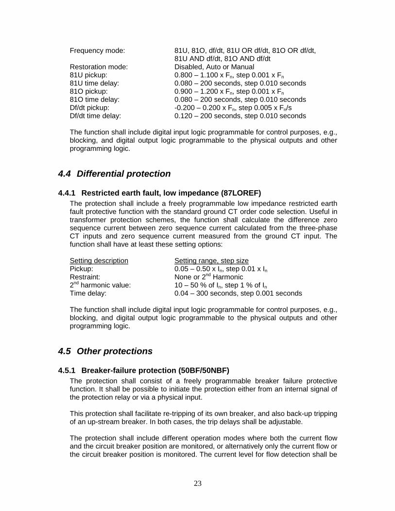
Frequency mode: 81U, 81O, df/dt, 81U OR df/dt, 81O OR df/dt, 81U AND df/dt, 81O AND df/dt
Restoration mode: Disabled, Auto or Manual 81U pickup: 0.800 – 1.100 x Fn, step 0.001 x Fn 81U time delay: 0.080 – 200 seconds, step 0.010 seconds 81O pickup: 0.900 – 1.200 x Fn, step 0.001 x Fn 81O time delay: 0.080 – 200 seconds, step 0.010 seconds Df/dt pickup: -0.200 – 0.200 x Fn, step 0.005 x Fn/s Df/dt time delay: 0.120 – 200 seconds, step 0.010 seconds The function shall include digital input logic programmable for control purposes, e.g., blocking, and digital output logic programmable to the physical outputs and other programming logic.
4.4 Differential protection
4.4.1 Restricted earth fault, low impedance (87LOREF) The protection shall include a freely programmable low impedance restricted earth fault protective function with the standard ground CT order code selection. Useful in transformer protection schemes, the function shall calculate the difference zero sequence current between zero sequence current calculated from the three-phase CT inputs and zero sequence current measured from the ground CT input. The function shall have at least these setting options: Setting description Setting range, step size Pickup: 0.05 – 0.50 x In, step 0.01 x In Restraint: None or 2nd Harmonic 2nd harmonic value: 10 – 50 % of In, step 1 % of In Time delay: 0.04 – 300 seconds, step 0.001 seconds The function shall include digital input logic programmable for control purposes, e.g., blocking, and digital output logic programmable to the physical outputs and other programming logic.
4.5 Other protections
4.5.1 Breaker-failure protection (50BF/50NBF) The protection shall consist of a freely programmable breaker failure protective function. It shall be possible to initiate the protection either from an internal signal of the protection relay or via a physical input. This protection shall facilitate re-tripping of its own breaker, and also back-up tripping of an up-stream breaker. In both cases, the trip delays shall be adjustable. The protection shall include different operation modes where both the current flow and the circuit breaker position are monitored, or alternatively only the current flow or the circuit breaker position is monitored. The current level for flow detection shall be

24
separately adjustable for phase currents and residual current. The function shall include at least these setting options: Setting description Setting range, step size Failure trip mode: Single-phase, Single-phase or ground, Single-
phase and ground current Failure mode: Current, Breaker status or Both Phase current dropout: 0.05 – 1.00 x In, step 0.05 x In Residual current dropout: 0.05 – 1.00 x In, step 0.05 x In Retrip time: 0.00 – 60.00 seconds, step 0.01 seconds Breaker fail time: 0.00 – 60.00 seconds, step 0.01 seconds The function shall include digital input logic programmable for control purposes, e.g., blocking, and digital output logic programmable to the physical outputs and other programming logic.
4.5.2 Overexcitation (24) The protection shall consist of a freely programmable overexcitation or volts-per-hertz element useful in adding valuable protection of the substation’s power transformer from a feeder relay with bus VT input connections. The function shall include at least these setting options: Setting description Setting range, step size Operation curve: Inverse or Definite time Voltage selection: Phase-to-ground, Phase-to-phase, Positive
sequence Phase selection: A or AB, B or BC, C or CA The function shall include digital input logic programmable for control purposes, e.g., blocking, and digital output logic programmable to the physical outputs and other programming logic.
4.5.3 Arc flash detection (AFD) The relay shall provide for ordering an optional freely programmable Arc flash detection (AFD) function. The function’s ability to detect light and current simultaneously shall be supported. During maintenance work at the substation, it shall be possible to change the operation criteria to light only by, e.g., a control input. The current monitoring levels shall be separately adjustable for phase currents and the ground current. It shall be possible to monitor the busbar, circuit breaker and cable compartments simultaneously by means of compartment dedicated sensors. Tripping command to the up-stream circuit breaker shall be selective based on the location of the arc per the detecting sensor. The operating time of the protection shall be less than 15 ms using the relay’s standard output contacts or less than 4 ms using the relay’s optional high-speed outputs. The function shall include at least these setting options: Setting description Setting range, step size Operation mode: Light only, Light+current or BI_controlled Phase pickup: 0.05 – 40.00 x In, step 0.01 x In Ground pickup: 0.05 – 8.00 x In, step 0.01 x In

25
The function shall include digital input logic programmable for control purposes, e.g., blocking, and digital output logic programmable to the physical outputs and other programming logic.
4.5.4 High impedance fault detection (HIZ) The relay shall provide for ordering an optional high-impedance (HIZ) fault detection function useful in detecting downed conductors whose fault current measures below normal overcurrent protection. The protection shall be a freely programmable function. The HIZ function shall use a measured zero sequence current value from the ground CT input when ordered. The functions shall have at least these setting options: Setting description Setting range, step size System type: Grounded or Ungrounded
4.6 Control
4.6.1 Automatic reclosing The protection shall consist of a freely programmable automatic reclosing function that supporting at least six auto-reclose attempts. The function shall include at least these setting options: Setting description Setting range, step size Reset (Reclaim) time: 0.1 – 1800 seconds, step 0.1 seconds Reclose times: 0.00 – 300 seconds, step 0.01 seconds Operations counter limit: 0 – 250 operations, step 1 operation Operations counter time: 1 – 250 minutes, step 1 minute Operations counter recovery: 1 – 250 minutes, step 1 minute The function shall include digital input logic programmable for control purposes, e.g., blocking, and digital output logic programmable to the physical outputs and other programming logic.
4.6.2 Synchronism check (25) The relay shall include a freely programmable synchronism check function. This function is necessary in validating synchronism between two separate systems, e.g., utility and local generation systems, separated by a breaker. The function shall include at least these setting options: Setting description Setting range, step size Mode: Dead Bus(B)/Line(L), Dead B-Live L, Live L-Dead B Voltage difference: 0.01 – 0.50 x Vn, step 0.10 x Vn Angle difference: 5 – 90 degrees, 1 degree Frequency difference: 0.001 – 0.100 x Fn, step 0.001 x Fn

26
The function shall include digital input logic programmable for control purposes, e.g., blocking, and digital output logic programmable to the physical outputs and other programming logic.
5 Measurements There shall be at least these measurement functions available in the replacement relay for the applicable analog current input connections to the relay:
5.1 Phase currents There shall be instantaneous metering values for phase A, B and C currents measured from the three-phase CT inputs. There shall be a freely programmable phase metering mode selectable as either RMS or DFT (fundamental) values. There shall be maximum demand values for phases A, B and C with freely programmable demand intervals of 1, 5, 10, 15, 30, 60 or 180 minutes stored in non-volatile memory (NVRAM). There shall be two levels each of user-programmable high and low warning current thresholds. The phase current metering shall have these accuracies or better: Measurements Accuracy1 IA, IB, IC ± 0.5% or ± 0.002 x In 1 0.01 – 4.00 x In, f = fn + 2 Hz
5.2 Ground current There shall be an instantaneous metering value for the measured ground current where a ground CT input is available. There shall be user-programmable phase and ground metering mode selectable as either RMS or DFT (fundamental frequency only) values. There shall be maximum demand values for phases A, B and C with user-programmable settable demand intervals of 1, 5, 10, 15, 30, 60 or 180 minutes stored in non-volatile memory (NVRAM). There shall be two levels each of user-programmable high and low warning current thresholds. The phase current metering shall have these accuracies or better:

27
Measurements Accuracy1
IG ± 0.5% or ± 0.002 x In 1 0.01 – 4.00 x In, f = fn
5.3 Current sequence components There shall be instantaneous values of the positive, negative and zero sequence current components included. There shall be two levels each of user-programmable high and low warning current thresholds. The sequence current metering shall have these accuracies or better: Measurements Accuracy1
I1, I2, I0 ± 1.0% or ± 0.002 x In 1 0.01 – 4.00 x In, f = fn
5.4 Phase voltages There shall be instantaneous metering values for phase A, B and C voltages measured from the three-phase VT inputs. There shall be user-programmable phase and ground metering mode selectable as either RMS or DFT (fundamental) values. There shall be two levels each of user-programmable high and low warning voltage thresholds. The voltage metering shall have these accuracies or better: Measurements Accuracy1
VA, VB, VC ± 0.5% or ± 0.002 x Vn 1 0.01 – 1.15 x Vn, f = fn + 2 Hz
5.5 Voltage sequence components There shall be instantaneous values of the positive, negative and zero sequence voltage components included. The voltage metering shall have these accuracies or better: Measurements Accuracy (Range: 0.01 – 1.15 x Vn) V1, V2, V0 ± 1.0% or ± 0.002 x Vn

28
5.6 Single- and three-phase power, energy and power factor There shall be instantaneous values of three-phase apparent, active and reactive power, active and reactive energy and power factor measurements included. There shall be freely programmable unit settings for the power and energy measurements as “Kilo” or “Mega”. There shall be a freely programmable reference direction setting for the active and reactive power measurements. There shall be freely programmable initial forward and reverse energy measurements for knowledge of import and export energy flows. The power, energy and power factor metering shall have these accuracies or better: Measurements Accuracy1
Power (S, P, Q) ± 1.5% Energy (Wh, VArh) ± 1.5% Power factor (pf) ± 0.015 1 All three phase currents: 0.01 – 1.20 x In, All three phase voltages: 0.50 – 1.15 x Vn, f = fn + 1 HzActive power and energy in range |pf| > 0.71 Reactive power and energy in range |pf| < 0.71
5.7 Frequency There shall be instantaneous values of the power system frequency included.
6 Records, load profile and time synchronization The replacement relay shall be capable of recording and storing in non-volatile memory (NVRAM) significantly more sequence of event (SOE) records, fault records and digital fault recordings (DFR), with each record date and time stamped, than what was possible in the DPU2000R. The SOE records, Fault records and DFR status shall be viewable from the LHMI LCD. The DFR data shall be retrievable using a web server interface and the relay’s user software tool. The retrieved DFR files shall be saved in COMTRADE format. The relay shall be capable of storing load profile data in NVRAM. The relay shall provide for time synchronization methods for available Ethernet and serial communication networks.

29
6.1 Sequence of events (SOE) records The SOE information must be accessible locally via the LHMI on the relay front panel or remotely via the relay’s user software tool. The information should further be accessible, either locally or remotely, using a web-browser based user interface embedded in the relay. The SOE shall record and store in NVRAM a minimum of 1024 records, each record having an event number, event description and date and time stamp. The non-volatile memory must retain its data in cases of temporarily loss of the relay’s auxiliary control power supply. The event log should facilitate detailed pre- and post-fault analyses of feeder faults and disturbances.
6.2 Fault records The relay shall store a minimum of 128 fault records. The records must enable the user to analyze the four most recent protection trips issued by the relay. Each record shall include at least the current and, where applicable, voltage magnitudes, the date and time stamp and the percentage of trip threshold each protection function attained at the time the trip was issued. It must be possible to trigger the fault recording by the pickup signal or the trip signal of a protection function or both.
6.3 Digital fault recorder (DFR) records The relay shall include a freely programmable digital fault recorder that records analog inputs, digital logic signals and binary (physical) inputs. The sample frequency shall be selectable, maximum sample frequency being no less than 32 samples-per-cycle or 1920 Hz in 60 Hz power system. The recording time shall be selectable, including the pre-trigger time. It must be possible to trigger the recording function by an analog channel when the measured value falls below or exceeds the set triggering value or manually locally and remotely. The digital signal channels should be capable of triggering a recording on the digital signal’s rising-edge, falling-edge or both. There shall be user programmability of the triggering channels in order to prevent successive recordings triggered by the same source. It shall be possible to record either waveforms or trends of the analog channels. When the maximum number of channels is connected, utilizing the highest sampling frequency, at least two recordings, each with a length of 10 seconds, shall be supported.
6.4 Load profile The relay shall include a freely programmable load profile feature for single breaker applications. The load profile feature shall record per-phase currents, voltages, watts and VArs measurements every demand time constant interval with user

30
programmability to define the recorded measurements. With twelve measurements defined, the feature shall comprise enough memory for at least 40 days for a demand time interval of 15 minutes.
6.5 Time synchronization The relay shall support the following time synchronization methods with a time stamp resolution of one (1) millisecond: • Simple Network Time Protocol (SNTP) • Inter-Range Instrumentation Group – Time Code Format B (IRIG-B) per these
specifications:
Description Value IRIG-B time code format B004, B0051 Isolation 500V, 1 min Modulation Unmodulated Logic level TTL level
1 According to 200—04 IRIG standard.
7 Condition monitoring The replacement relay shall include these minimum set of condition monitoring functions.
7.1 Circuit breaker (52CM) The relay shall include a freely programmable circuit breaker condition monitoring function. The monitoring shall include interrupted current (I2t) accumulators, operation counters, breaker operation and inactivity timing, SF6 gas pressure and spring charge status and associated alarm and lockout settings whose operation may proactively serve to initiate breaker maintenance and protect the breaker from damage upon further operation.
7.2 Self-supervision The device shall include a self-supervision system that continuously monitors the state of the relay hardware and the operation of the relay software. Any fault or malfunction detected must be used for alerting the operator. A permanent device fault must block the protection functions of the relay to prevent incorrect device operation and drop out or de-energize its self-check alarm relay output.

31
7.3 Trip circuit monitoring (TCM) The relay shall include the ability via programmable logic to monitor the breaker trip circuit and provide an alarm signal when a failure is detected with the breaker in a closed position.
7.4 Current circuit monitoring (CCM) The relay shall include a fully programmable current circuit monitoring function to check the integrity of the CT secondary wiring. The function shall include digital input logic programmable for control purposes, e.g., blocking, and digital output logic programmable to the physical outputs and other programming logic.
7.5 Fuse failure (60) The relay shall include a fully programmable fuse failure monitoring function. The function shall detect a blown VT fuse condition and alarm so that critical protection functions using the three-phase VT inputs may be disabled preventing potential unwanted operations. The function shall include digital input logic programmable for control purposes, e.g., blocking, and digital output logic programmable to the physical outputs and other programming logic.
7.6 Power quality (PQ) The relay shall provide for ordering an optional freely programmable power quality feature that measures and records current and voltage harmonics and short duration system disturbances. The PQ functions shall include these features per the IEEE 1159 standard:
• Current total demand distortion (TDD) • Voltage total harmonic distortion (THD) • Sags(Dips), Swells and Interrupts • Voltage unbalance
The function shall include digital input logic programmable for control purposes, e.g., blocking, and digital output logic programmable to the physical outputs and other programming logic.
7.7 Cable fault detection (CFD) The relay shall provide a freely programmable cable fault detection function that monitors the feeder for incipient and permanent underground cable faults. Such faults are characterized by short duration signals, e.g., less than one cycle, and are not detected by traditional protection functions that have pickup settings and coordination-driven time delays.

32
The function shall include digital input logic programmable for control purposes, e.g., blocking, and digital output logic programmable to the physical outputs and other programming logic.
7.8 Fault location The relay shall include a freely programmable fault location function capable of providing a distance to fault calculation for a homogeneous radial distribution feeder. The function shall be capable of providing a distance calculation for such a feeder up to 100 miles or kilometers in length.
8 Communication interfaces The replacement relay shall be of a “native” IEC61850 design, thus offering an optimal connection interface in IEC61850-8-1-based substation automation systems and enabling high-speed peer to peer control schemes, while offering serial communications similar to the DPU2000R. The communication card shall include an RJ45 Ethernet port interface. This interface will serve as a ‘future proof’ feature enabling utilization of Ethernet-based status and control solutions and rapid conversion from an existing serial communications technology to an Ethernet topology. Having this interface available eliminates the need to order and replace communication cards in the future. The serial communications shall include user selectable Modbus or DNP3.0 Level 2 protocol without need to specify it in an ordering code. The Ethernet connection shall support multiple remote simultaneous communication sessions for SCADA, Engineering and Maintenance and time synchronization (SNTP) including at least these communication protocols: • Modbus over TCP/IP • DNP3.0 Level 2 over TCP/IP • IEC61850 • SNTP The relay shall include an embedded web server accessible via industry standard browsers such as Microsoft’s Internet Explorer and Mozilla’s Firefox. The browser must at least provide ability to review relay status, sequence of events, review and retrieve protection settings and digital fault (waveform) recording data. On the front side of the relay there shall be a local communication interface with an RJ45 connector. This connection shall be dedicated for the protection relay local user interface allowing viewing of metering values, records, reviewing and editing of settings and retrieving digital fault recordings via its embedded web server or user software tool.

33
8.1 IEC61850 compliance and GOOSE messaging The relay shall be compliant to the IEC61850-8-1 standard in all order codes and capable of utilizing GOOSE messages, as described in the IEC61850-8-1 standard, for horizontal level communication. The GOOSE-message presentation and mapping shall be carried out in the relay via its user software tool exposing the GOOSE incoming and outgoing signals to a similar manner as seen with mapping a relay’s binary (physical) inputs and outputs. The GOOSE signal performance has to be in accordance with type 1A and fulfill the requirements of class P1.
8.2 User authorization The relay shall support at least these four independent user authorization levels: Authorization level Authorization description Viewer Ability restricted to viewing data only; no controls or
setting edits. Operator Ability to perform controls; no setting edits Engineer Ability to perform setting edits; no controls Administrator Ability to view data, perform controls and edit
settings; no restrictions There shall be settable separate passwords for each user authorization level. The password shall be different for local and remote access.
9 Setting and configuration software The relay shall include a freeware version of its user software tool necessary for its setting and configuration.
10 Electrical and environmental conditions The relay must fulfill these qualification standards and environmental conditions:
10.1 Insulation compatibility Description Value Reference Dielectric test IEEE C37.90-2005,
• Non-communication 2 kV, 1 min IEC 60255-5, • Communication 500 V, 1 min IEC 60255-27
Impulse voltage test IEEE C37.90-2005,

34
• Non-communication 5 kV, 1.2/50 μs, 0.5 J IEC 60255-5, • Communication 1 kV, 1.2/50 μs, 0.5 J IEC 60255-27
Insulation resistance measurements >100 MΩ, 500 VDC IEC 60255-5 Protective bonding resistance <0.1 Ω, 4 A, 60 s IEC 60255-27
10.2 Environmental conditions and tests The relay shall meet these conditions and tests:
10.2.1 Environmental conditions Description Value Operating temperature range: -25...+55ºC (continuous) Short-time temperature range: -40...+85ºC (<16h) Transport and storage temperature: -40...+85ºC Relative humidity: <93%, non-condensing Altitude: Up to 6561 ft.
10.2.2 Environmental tests Description Value Reference Dry heat test: +55°C 96h IEC 60068-2-2
+85°C 16h1, 2 +85°C 12h1, 2 IEEE C37.90-2005 Dry cold test: -25°C 96h IEC 60068-2-1
-40°C 16h1, 2 -40°C 12h2, 3 IEEE C37.90-2005 Damp heat test: 6 cycles (12h + 12h) at IEC 60068-2-30
+25...+55°C, Rh >93%, +25°C, Rh = 95%, 96h IEEE C37.90-2005 Change of temperature test: 6 cycles (12h + 12h) at IEC 60068-2-14
+25...+55°C Storage: 96 h at -40°C IEC 60068-2-48,
96 h at +85°C IEEE C37.90-2005 1 It is acceptable relay with LC communication interface has maximum operating temperature of +70 °C. 2 It is acceptable that LCD may be unreadable provided relay is still operational. 3 It is acceptable for 24/48 V DC (Type 2) control voltage the minimum start-up is 48 V DC at -40 °C.
10.3 Electromagnetic compatibility Description Value Reference 1 MHz/100 kHz burst disturbance test IEC 61000-4-18,
• Common mode 2.5 kV IEC 60255-22-1 class III, • Differential mode 2.5 kV IEEE C37.90.1-2002

35
3, 10, 30 MHz burst disturbance test IEC 61000-4-18,
• Common mode 2.5 kV IEC 60255-22-1 class III Electrostatic discharge test IEC 61000-4-2,
• Contact discharge 8 kV IEC 60255-22-2, IEEE C37.90.3-2001
• Air discharge 15 kV Radio frequency interference test
• f = 150 kHz…80 MHz 10 V/m (rms) IEC 61000-4-6, IEC 60255-22-6, class III
• f = 80 kHz...2700 MHz 10 V/m (rms) IEC 61000-4-3, IEC 60255-22-3, class III
• f = 900 MHz 10 V/m (rms) ENV 50204, IEC 60255-22-3, class III
• f = 80…1000 MHz 20 V/m (rms) IEEE C37.90.2-2004 Fast transient disturbance test IEC 61000-4-4,
• All ports, common mode 4 kV IEC 60255-22-4, IEEE C37.90.1-2002
• All ports, differential mode 4 kV Surge immunity test IEC 61000-4-5,
• Communication 1 kVln IEC 60255-22-5 • Other ports 4 kVln
2 kVll Power frequency magnetic field immunity test (50Hz) IEC 61000-4-8
• Continuous 300 A/m • 1…3 s 1000 A/m
Pulse magnetic field immunity test 1000 A/m, IEC 61000-4-9 6.4/16 µs Damped oscillatory magnetic field immunity test IEC 61000-4-10
• 2 s 100 A/m • 1 MHz 400 transients/s
Voltage dips and short interruptions 30% / 10 ms IEC 61000-4-11
60% / 100 ms 60% / 1000 ms >95% / 5000 ms
Power frequency immunity (Physical inputs) IEC 61000-4-16,
• Common mode 300 V (rms) IEC 60255-22-7, class A • Differential mode 150 V (rms)
Conducted common mode disturbances IEC 61000-4-16
• 15 Hz…150 kHz Test level 3 (10/1/10 V rms)

36
Emission tests ENC 55011, class A,
• Conducted IEC 60255-25 0.15 – 0.50 MHz <79 dB (μV) quasi peak <66 dB (μV) average 0.5 – 30 MHz <73 dB (μV) quasi peak <60 dB (μV) average
• Radiated
30...230 MHz <40 dB (μV/m) quasi peak, measured at 10 m distance
• 230...1000 MHz <47 dB (μV/m) quasi peak, measured at 10 m distance
10.4 Mechanical testsDescription Value Reference Vibration tests (sinusoidal) Class 2 IEC 60068-2-6 (test Fc), Class 2 IEC 60255-21-1 Shock and bump tests Class 2 IEC 60068-2-27 (test Ea Shock)
Class 2 IEC 60068—2-29 (test Eb Bump) Class 2 IEC 60255-21-2
Seismic tests Class 2 IEC 60255-21-3 Mechanical durability IEC60255-6, IEEE C37.90-2005
• Withdrawals & insertions 200 • Control adjustments 200
10.5 EMC complianceDescription Reference EMC directive 2004/108/EC Standard ENC 50263 (2000), ENC 60255-26 (2007)
11 Quality assurance and standards The provider of the device must have a quality system in place which aims at securing a high quality of the manufactured device. The relay shall comply with RoHS directive 2002/95/EC. The relay shall be UL Listed per UL 508 standard for Industrial Control Equipment and Canadian Standard CSA C22.2 No. 14. The relay shall include a warranty for not less than 12 years.

37
12 Approved manufacture(s) and product(s) Manufacturer Product ABB Inc. REF615R Order code HWFAA…