for walk-in coolers / freezers · for walk-in coolers / freezers. 2 assembly instructions...
TRANSCRIPT
www.stuv.de 1
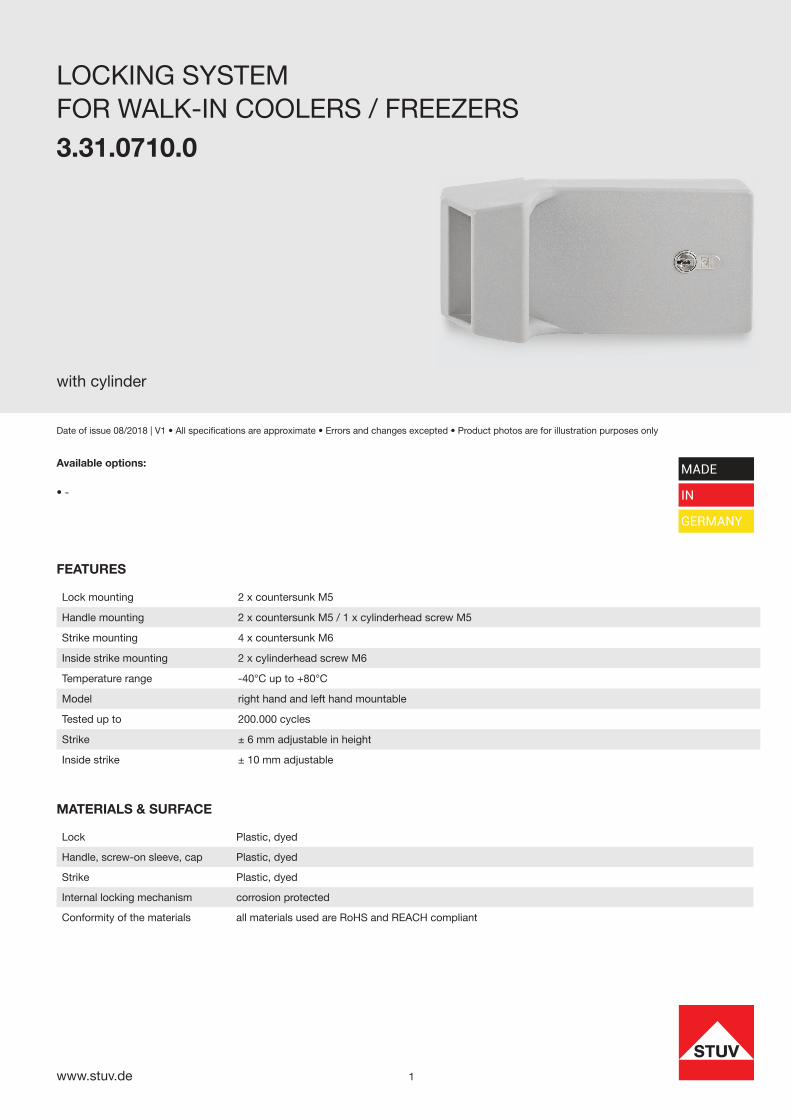
LOCKING SYSTEM
3.31.0710.0
with cylinder
Date of issue 08/2018 | V1 • All specifi cations are approximate • Errors and changes excepted • Product photos are for illustration purposes only
Lock Plastic, dyed
Handle, screw-on sleeve, cap Plastic, dyed
Strike Plastic, dyed
Internal locking mechanism corrosion protected
Conformity of the materials all materials used are RoHS and REACH compliant
MATERIALS & SURFACE
Available options:
• -
MADE
IN
GERMANY
Lock mounting 2 x countersunk M5
Handle mounting 2 x countersunk M5 / 1 x cylinderhead screw M5
Strike mounting 4 x countersunk M6
Inside strike mounting 2 x cylinderhead screw M6
Temperature range -40°C up to +80°C
Model right hand and left hand mountable
Tested up to 200.000 cycles
Strike ± 6 mm adjustable in height
Inside strike ± 10 mm adjustable
FEATURES
FOR WALK-IN COOLERS / FREEZERS
www.stuv.de 2
ASSEMBLY INSTRUCTIONS
3.31.0710.0
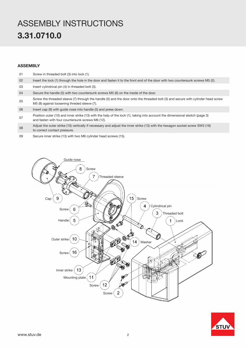
01 Screw in threaded bolt (3) into lock (1).
02 Insert the lock (1) through the hole in the door and fasten it to the front end of the door with two countersunk screws M5 (2).
03 Insert cylindrical pin (4) in threaded bolt (3).
04 Secure the handle (5) with two countersunk screws M5 (6) on the inside of the door.
05Screw the threaded sleeve (7) through the handle (5) and the door onto the threaded bolt (3) and secure with cylinder head screw M5 (8) against loosening threded sleeve (7).
06 Insert cap (9) with guide nose into handle (5) and press down.
07Position outer (10) and inner strike (13) with the help of the lock (1), taking into account the dimensional sketch (page 3)and fasten with four countersunk screws M6 (12).
08Adjust the outer strike (10) vertically if necessary and adjust the inner strike (13) with the hexagon socket screw SW3 (16)to correct contact pressure.
09 Secure inner strike (13) with two M6 cylinder head screws (15).
ASSEMBLY
Guide nose
Screw
Threaded sleeve
Screw
Cylindrical pin
Threaded bolt
Lock
Screw
Handle
Cap
Outer strike
Screw
Inner strike
Mounting plate
Screw
Screw
Washer
www.stuv.de 3
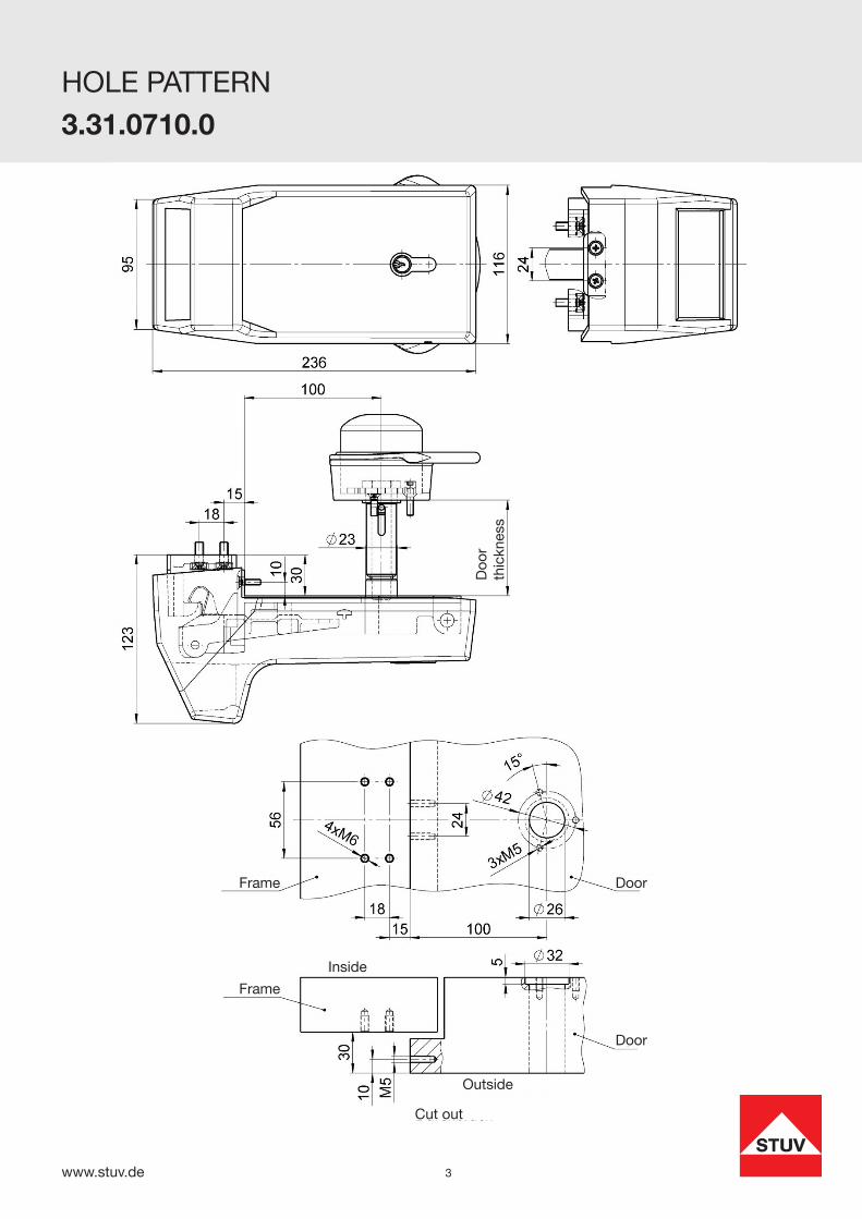
HOLE PATTERN
3.31.0710.0
Frame
Frame
Door
Door
Outside
Inside
Cut out
Doo
r th
ickn
ess