for water sensitive urban design - … sensitive urban design version 1.1 ... assessments and...
TRANSCRIPT

Blacktow n City Council has prepared an Integrated Water
Cycle Management (IWCM) Development Control Plan
(DCP) to mit igate the impact of urban development on
local w aterw ays w ithin the area.
This Handbook has been prepared to assist developers
and includes:
Issues to be considered w hen assessing the natural
attributes of a site, that is site considerat ions
Advice on the select ion of typical treatment
measures for potable w ater conservation,
stormw ater quality and w aterw ay stability
Examples of how treatment measures can be
integrated into streetscapes
Guidance on the modelling of treatment measures
and strategies using the Model for Urban
Stormw ater Improvement Conceptualisat ion
(MUSIC)
An indicative plant list for treatment measures in the
Blacktow n Local Government Area (LGA).
DEVELOPER HANDBOOK
for
WATER SENSITIVE URBAN DESIGN
Version 1.1 November 2013

Page 1
CONTENTS This Handbook has been prepared to assist developers in achieving the objectives and implementing the controls relating to water conservation, water quality and waterway stability measures contained in the section on integrated water cycle management in Council’s Development Control Plan. Integrated water cycle management is processes or practices used to control the natural cyclical process whereby atmospheric water falls as rain and infiltrates to groundwater or runs off as stormwater to receiving waters and is then evaporated back into the atmosphere. At various stages of the process, water may also be released into the atmosphere (transpired) by living things or infiltrate to groundwater. This Handbook can be used in the preparation of a development application and/or integrated water cycle management strategy/report and relates to the activities of conducting site assessments and conceptual design. This Handbook contains 5 parts.
PART 1 SITE CONSIDERATIONS...................................................................2
PART 2 TREATMENT MEASURE SELECTION..............................................12
PART 3 STREETSCAPES..............................................................................53
PART 4 MUSIC MODELLING GUIDE.............................................................67
PART 5 VEGETATION SELECTION GUIDE...................................................98

Page 2
HANDBOOK PART 1: SITE CONSIDERATIONS
1 INTRODUCTION ............................................................................................................ 3
2 SITE CONSTRAINTS ..................................................................................................... 4
2.1 Contributing Catchment Area............................................................................. 4
2.2 Pollution Type and Load .................................................................................... 4
2.3 Landform ............................................................................................................ 4
2.4 Soil and Groundwater ........................................................................................ 5
2.5 Existing Development ........................................................................................ 6
3 DOWNSTREAM CONSTRAINTS .................................................................................. 8
3.1 Receiving Waterways ........................................................................................ 8
3.2 Vegetation .......................................................................................................... 9
4 REFERENCES ............................................................................................................. 10

Page 3
1 INTRODUCTION
This section of the Handbook outlines the issues to be considered when assessing the natural attributes of a site. An assessment of the site should be the first step in developing an Integrated Water Cycle Management Strategy or Report. The range of physical constraints to be addressed through this process includes:
Contributing catchment size.
Pollutant type and load.
Landform (for example, the site slope and steepness).
Soil type and groundwater level.
Existing development.
Receiving waterways.
Vegetation. Table 1 provides a summary of the physical constraints affecting various treatment measures. The summary has been adapted from the Technical Design Guidelines for South East Queensland (Moreton Bay Waterways and Catchments Partnership, 2006). Table 1 identifies the extent to which treatment measures are constrained:
C = the site condition is a constraint and may preclude use.
D = the site condition is a constraint but may be overcome through appropriate design.
= the site condition is generally not a constraint. The subsequent sections provide further details on the various physical constraints affecting the feasibility of treatment measures. Table 1: Summary of physical constraints affecting treatment measures (after Moreton Bay Waterways and Catchments Partnership, 2006)
Treatment measure
Site condition
Ste
ep
sit
e
Sh
allo
w b
ed
rock
Acid
su
lfate
so
ils
Cla
y
so
ils
(lo
w
perm
eab
ilit
y)
San
dy
so
ils
(h
igh
perm
eab
ilit
y)
Hig
h w
ate
r ta
ble
Hig
h s
ed
imen
t in
pu
t
Lan
d a
vail
ab
ilit
y
Swales and buffer strips D D D D D C
Bioretention swales C C C C D C
Bioretention basins D D D D D C
Constructed wetlands C D C D D D C
Treatment / storage ponds D C C C C D C
Rainwater tanks D
GPTs D D
Pit traps D
Porous paving D D D D D D

Page 4
2 SITE CONSTRAINTS
2.1 Contributing Catchment Area
The flow rate and the flow volume of water to be managed increases as the catchment size increases. Whilst options to manage this include detention and breaking large catchments up into smaller sub-catchments, economies of scale and lifecycle costs must be considered. Larger catchments for example may offer more options for stormwater harvesting and reuse. Also some GPTs, ponds and wetlands also have higher cost benefits for larger catchments. Conversely, smaller catchments are preferable for pit traps and Bioretention swales which have low cost benefits in larger catchments.
2.2 Pollution Type and Load Integrated water cycle management is about delivering water sensitive designs that address water quality and quantity. Some treatment measures can address water quality and quantity in a single design, however as catchment size this becomes increasingly difficult and it is often easier to address the issues individually. However it should be considered that a detention basin left covered in rubbish and debris after a storm or an oil/grit trap located on 20 hectares is not ideal or compromising the objectives of installing the measure. Also another common example of an oversight is the installation of bioretention swales areas with hydrocarbon spill potential. Pollution types are reasonably easy to identify however, the potential loads can often be harder to predict. Site management activities, auditing, street sweeping, imperviousness, mowing techniques, proximity to sporting events or other public gatherings, can all greatly increase or decrease potential pollutant loads. When selecting devices catchment characteristics such as land use should be considered to appropriately identify the pollution types and loads that need to be treated. The selection of measures must also consider the nature of the pollutants and whether they are organic or inorganic. Anthropogenic litter such as newspapers and plastic bags for example behave differently in their potential to decay. Likewise silt or clay can fill up bioretention swales, whereas most fine particulate organics can decay away and have minimal impact. High loads of fine particulates however can smother and coat the swale.
2.3 Landform Landform can be a constraint to the location of treatment measures. Two issues are particularly important:
Slope - Many treatment measures will not work effectively on steep slopes, and are best located in the flatter areas of the landscape. Slopes of 1 to 5 per cent are ideal; however the suitability of a site will depend on the treatment measure proposed. For example, bioretention systems can be designed for steeper sites where the slope can be accounted for by bioretention cells or a larger number of smaller treatment measures, or by treatments being directed across the slope not down the slope, whereas wetlands are more easily integrated into flatter sites. Some GPTs use the velocity of incoming water to increase performance whilst other rely on low velocity to aid settlement, so slope can also be a critical component in the decision of primary treatment options.
Shallow bedrock - Shallow bedrock may constrain the location of some treatment measured by restricting the depth available for treatment.

Page 5
2.4 Soil and Groundwater A site assessment of soil and groundwater conditions in the Blacktown Local Government Area (LGA) will specifically need to consider:
Soil permeability.
Salinity.
Groundwater.
Soil Permeability
High permeability soils can be a constraint to treatment measures designed to hold permanent water, as it can be difficult to ensure that they will hold water in such an environment. Low permeability soils do not pose a constraint to most treatment measures; the exception is infiltration, which relies on high permeability. Additionally, some treatment measures are designed to retain water and act as a water feature as well as a treatment solution, in these instances use of an impermeable liner is required. In the Blacktown LGA, the majority of soils have a low permeability, posing a constraint to those treatment measures using infiltration. Salinity Salinity is a major issue affecting Western Sydney and is considered a constraint to land development. Salinity is contributed to by the flow through of water, poor soil drainage, cyclic soil inputs and local soil formations (BCC, 2007). The map for Salinity Potential in Western Sydney (DLWC, 2002) identifies the entire Blacktown LGA as having a moderate to known potential of salinity. Site indicators of salinity potential are described in Table 2. Table 2: Salinity potential categories relevant to the Blacktown LGA
Salinity potential Site description / indicators
Known – saline soils identified
Scalding.
Salt efflorescence.
Vegetation die-back.
Salt tolerant plant species.
Water logging.
High – Areas predisposed to salinity
Typical of lower slopes and streamlines, which have a propensity to being waterlogged.
Movement of water through soil profile is slow.
Site conditions similar to those of Known salinity potential.
Moderate
Wianamatta group shales and tertiary alluvial terraces (not already defined as having High or Known salinity potential).
Scattered areas of scalding.
Salt affected building.
Salt tolerant plants.
Urban development can exacerbate salinity issues by changing the flow of groundwater. Implementation treatment measures such as bioretention systems can further raise the salinity profile of the catchment by encouraging infiltration of treated stormwater into the groundwater. The report Site Investigation for Urban Salinity (DLWC, 2002) is a useful tool in guiding a site assessment for salinity potential. The guide suggests that the investigation be divided into four phases:

Page 6
Phase 1 - involves a detailed desk top review and preliminary site visit to determine the type and quantity of salt available at the site. The review and site visit should consider soil profile, groundwater condition, landform and the location of any salinity outbreaks.
Phase 2 - involves a detailed site assessment in order to develop a three dimensional soil and groundwater profile of the site. Factors to be analysed include topography, lithology, site condition (such as percent groundcover), hydrology and soils.
Phase 3 - requires the test results from Phase 2 to be presented and compared to relevant standards and technical documents. It is suggested that a distribution map of the site soil and topography be prepared as this is easily compared to the proposed development layout. The main features of the map should include soil and landform units, drainage lines, locations of all site investigations conducted as part of Phase 2, topographic contours, vegetation, and a legend, scale and north direction.
Phase 4 - considers the impact and management of the proposed development on the soil and groundwater profile developed in the previous three phases. The assessment should address how the proposed development will affect the flow through and surface flow of water, the impact of altered water and salt profiles on the development and/or construction (for example, corrosion of structures), and how the development will minimise its affect on the groundwater and soil profile (for example, in the Blacktown LGA, no infiltration of stormwater to in-situ soils or groundwater will be allowed).
The Site Investigation for Urban Salinity provides a comprehensive list of resources to assist in conducting the site visit and collecting the required information. Further guidance on salinity includes:
Guide on building in a saline environment (DIPNR, 2003) – construction in saline areas.
Urban Salinity in Western Sydney (www.wsroc.com.au) – website providing additional papers, guides and codes of practice, particularly targeted at salinity in Western Sydney.
Groundwater
The impact of a treatment measure on groundwater, and alternatively groundwater on treatment measures should be carefully considered. In the Blacktown LGA, the water table is near the surface in many locations and some treatment measures such as wetlands or bioretention systems may need to be carefully designed to avoid interaction. Advice for appropriate management should be sought from specialists in soil and groundwater management.
2.5 Existing Development Existing development may include past development on the site, development upstream or downstream of the site, or underground and overhead services. Most existing development can be understood through a site walk over. A services search should be undertaken to identify potential underground services (such as water, sewer, gas) at the site as services can be a significant constraint to the location of treatment measures and should be considered early in the design stages. During the design stages, more detailed survey of existing development can be conducted as required. Development associated with previous land uses may either facilitate treatment (for example, an old farm dam could be converted to a sediment basin or other type of treatment measure) or could form a constraint (for example, there may be a need to preserve heritage items on

Page 7
site, meaning that some areas can’t be utilised for treatment measures). Similarly, adjacent development may either form an opportunity (for example, some non-potable water demands within existing development could be met with excess stormwater from the proposed development) or it could present a constraint (for example uncontrolled stormwater flows may enter the site from an adjacent development).
Page 8
3 DOWNSTREAM CONSTRAINTS
3.1 Receiving Waterways Any site assessment conducted will need to include an assessment of waterways downstream of the site that will be impacted by the development. This stage of the site assessment is best conducted with input from a geomorphologist and ecologist. In some instances, environmental flows may be required, so first flush stormwater runoff may need to be directed to the creek, however there also exists the potential to direct too much flow into a creek and in these instances detention may be required. The requirements for environmental flows should be determined early in the design phase of any developments. The former Department of Water and Energy through its Riparian Corridor Management Study (RCMS) established guidance on the minimum vegetated core riparian zone widths needed for new urban developments in NSW. The Study identified three categories to protect, maintain and enhance riparian zones:
Category 1 - an environmental corridor, 40 meters (plus a 10 meter wide buffer) either side of the watercourse (measured from top of bank).
Category 2 - terrestrial and aquatic habitat, 20 to 30 meters, or to the extent of remnant riparian vegetation whichever is the widest (plus a 10 meter wide buffer) either side of the watercourse (measured from top of bank).
Category 3 - bed and bank stability / water quality, 10 meters either side of the watercourse (measured from top of bank).
The Study calls for the provision of a suitable interface or “buffer zone” between the riparian area and urban development (roads, playing fields, open space) to minimise edge affects, and the location of services (power, water, and \water quality treatment ponds) outside of the core riparian zone. The site assessment should also identify whether existing overland flows or stormwater outflows from the site are dispersed or concentrated in nature. For example, dispersed flows often occur at the edge of a wetland or in relatively flat areas and concentrated flows where there is an existing channel, constructed drain, culvert or pipe. Future development should maintain the physical form of stormwater outflows (dispersed or concentrated) wherever possible. The site assessment may identify that a waterway on or downstream of the site has already been eroded due to past development impacts. Where a broad, undefined drainage depression has already been replaced by an incised channel, it is no longer worthwhile to apply the objectives for undefined drainage depressions (the only stream stability requirement would be management of the 2 year Average Recurrence Interval (ARI) peak flows). Alternatively, the site assessment may identify that active erosion is still underway in a waterway on the site. If this is the case, rehabilitation works may be necessary to stabilise the waterway and minimise further erosion. Such works would help ensure that the full benefit of treatment measures is realised. Figure 1: Castlereagh Ironbark
Forest (BCC, 2008)

Page 9
3.2 Vegetation Biodiversity is affected by the degradation and loss of terrestrial ecosystems. The location of treatment measures is often influenced by concurrent requirements to protect riparian zones (as required by the NSW Department of Water and Energy for Category 1, 2 and 3 streams) as well as flora, fauna and vegetation communities (as required by the NSW Federal and State Government in accordance with the Commonwealth Environment Protection and Biodiversity Conservation Act 1999 and NSW Threatened Species Conservation Act 1995). When evaluating a site, consideration must be given to avoiding protected areas and safeguarding protected areas from any disturbances resulting from the construction or function of any proposed treatment measures. An ecological site assessment conducted by an ecologist with experience in flora, fauna and vegetation communities of the Cumberland Plain would help identify the key areas that need to be protected.

Page 10
4 REFERENCES
Blacktown City Council 2008, Salinity, Available online at http://www.blacktown.nsw.gov.au/environment/issues/salinity.cfm
Moreton Bay Waterways and Catchments Partnership 2006 WSUD Technical Design Guidelines for South East Queensland Version 1 June 2006. Available online at: http://www.healthywaterways.org/FileLibrary/wsud_tech_guidelines.pdf
NSW Department of Infrastructure Planning and Natural Resources 2003 Building in a Saline Environment Available online at http://www.wsroc.com.au/page.aspx?pid=58&vid=1&fid=115&ftype=True
NSW Department of Land and Water Conservation 2002 Guidelines to accompany Map of Salinity Potential in Western Sydney NSW Department of Land and Water Conservation 2002 Site Investigations for Urban Salinity Available online at http://www.wsroc.com.au/

Page 11
Page intentionally left blank

Page 12
HANDBOOK PART 2: TREATMENT MEASURE SELECTION GUIDE
5 INTRODUCTION .......................................................................................................... 13
6 INITIATIVES FOR WATER CONSERVATION ............................................................ 16
6.1 Potable Water Conservation or Commercial, Residential and
Industrial Applications ...................................................................................... 16
6.2 Supplementing Potable Mains Water .............................................................. 17
6.3 Rainwater Tanks .............................................................................................. 19
6.4 Stormwater Harvesting, Storage and Reuse ................................................... 23
7 INITIATIVES FOR STORMWATER QUALITY ............................................................ 28
7.1 Gross Pollutant Traps (GPTs) .......................................................................... 29
7.2 Vegetated Swales and Buffers......................................................................... 31
7.3 Bioretention Systems ....................................................................................... 37
7.4 Wetlands .......................................................................................................... 42
8 INITIATIVES FOR WATERWAY STABILITY .............................................................. 47
8.1 Stormwater Detention ...................................................................................... 47
9 REFERENCES ............................................................................................................. 51

Page 13
5 INTRODUCTION
This section of the handbook provides advice on the selection of typical treatment measures for potable water conservation, stormwater quality and waterway stability. Table 1 provides a summary of the objectives and targets contained within Part S of the Blacktown Development Control Plan (DCP) 2006, and shows how the treatment measures presented in this document can be used to meet those objectives and targets. This section of the handbook is presented in three main sections, which correspond to the requirements of the Blacktown DCP 2006, namely:
Water conservation.
Stormwater quality.
Waterway stability. Each of the sections provides information useful for the selection and preliminary sizing of treatment measures, including:
The purpose of each treatment measure and how it works.
Where the treatment measure would be most appropriately located in the urban landscape.
Important design considerations, including soil and vegetation selection for vegetated treatment measures. The design considerations point to the advantages and disadvantages, benefits and risks of each treatment measure.
Basic sizing information suitable for preliminary estimates.
Maintenance requirements.
References to more detailed information where relevant. It is recommended that any proponent required to prepared a Strategy to comply with Part S of the Blacktown DCP 2006 and coordinate with Blacktown City Council for the relevant policies and guidelines pertaining to open space, traffic control, stormwater and flood management as well as maintenance.

Page 14
Table 3: Summary of treatment measures in relation to urban water management objectives
Objectives Development type / receiving environment*
Performance targets (as per Part S of the Blacktown DCP 2006)
Recommended treatment measures to meet objectives and targets
Additional components to meeting the objectives and targets
Potable Water Conservation
To reduce consumption of potable water. To harvest rainwater and urban stormwater runoff for use where appropriate. To reduce wastewater discharge. To capture, treat and reuse wastewater where appropriate. To safeguard the environment by improving the quality of water run-off. To ensure infrastructure design is complementary to current and future water use.
Buildings and private open space.
New residential dwellings, including a residential component within a mixed use building and serviced apartments intended or capable of being strata titled, are to demonstrate compliance with State Environmental Planning Policy - Building Sustainability Index (BASIX). Buildings not affected by BASIX who are installing any water use fittings must meet minimum water conservation ratings as defined by the Water Efficiency Labelling and Standards (WELS) Scheme. Minimum WELS ratings for any water use fittings in these buildings are 3 star toilets, 3 star showerheads, 4 star taps and 3 star urinals. Water efficient washing machines and dishwashers should also be used wherever possible. Buildings not affected by BASIX should also investigate the use of rainwater tanks to supplement supply to outdoor use, toilets, laundry and hot water where appropriate.
Demand Management (WELS website http://www.waterrating.gov.au/). Rainwater tanks (Section 2.3). Stormwater harvesting, storage and reuse (Section 6.4).
Water-efficient fittings (toilets, shower heads and taps), plus rainwater tanks to meet outdoor, laundry, toilet flushing and / or hot water demands. Use of water-efficient local plant species in landscaping Water recycling (for example wastewater or greywater treatment and reuse).
Public open space.
For any water use within public open space (for example irrigation, water features, open water bodies / pools) an alternative water source must be identified to meet at least 80 per cent of all demand.
Rainwater tanks (Section 2.3). Stormwater harvesting, storage and reuse (Section 6.4).
Use of water-efficient local plant species in landscaping. Water recycling.

Page 15
Objectives Development type / receiving environment*
Performance targets (as per Part S of the Blacktown DCP 2006)
Recommended treatment measures to meet objectives and targets
Additional components to meeting the objectives and targets
Stormwater Quality
To safeguard the environment by improving the quality of stormwater run-off to achieve best practice standards.
Always applicable.
90 per cent reduction in the post development average annual gross pollutant (greater than 5 millimetres) load. 85 per cent reduction in the post development mean annual load of Total Suspended Solids (TSS). 65 per cent reduction in the post development mean annual load of Total Phosphorus (TP). 45 per cent reduction in the post development mean annual load of Total Nitrogen (TN).
Use of a stormwater treatment train, including treatment measures such as:
GPTs (Section 3.1).
Swales (Section 3.2).
Bioretention systems (Section 7.3).
Wetlands (Section 7.4).
Proprietary stormwater treatment measures. Rainwater and stormwater harvesting and reuse.
Waterway Stability
To control the impacts of urban development on channel bed and bank erosion by controlling the magnitude and duration of sediment-transporting flows.
All waterways (including lakes, wetlands and streams).
The post development duration of flows shall be no greater than 3 to 5 times than the stream forming flow for the undeveloped duration. The stream forming flow is defined as the following percentage of the 2 year Average Recurrence Interval (ARI) flow rate estimated for the catchment under natural conditions:
10 per cent - cohesion less (for example sandy) bed and banks.
25 per cent – moderately cohesive bed and banks.
50 per cent - cohesive (for example stiff clay) bed and banks.
Minimise impervious areas that are directly connected to the stormwater system.
Stormwater detention (Section 4.1). Bioretention basins (Section 7.3). Wetlands (Section 7.4).
Dispersed flows can be maintained using level spreaders or similar.

Page 16
6 INITIATIVES FOR WATER CONSERVATION
Potable mains water conservation seeks to reduce demand on water resources and wastewater discharges to the environment. Demand on potable mains water within the Blacktown Local Government Area (LGA) is expected to increase with an additional 66,000 homes to be built by the Growth Centres Commission in the north-west sector. Treatment measures appropriate to reducing potable mains water include:
Potable mains water conservation in residential and industrial applications (Section 2.1).
Supplementing potable mains water (Section 2.2).
Rainwater tanks (Section 2.3).
Stormwater harvesting, storage and reuse (Section 2.4).
6.1 Potable Water Conservation for Commercial, Residential and Industrial Applications
Opportunities for water conservation for new commercial developments are summarised in Table 4. Table 4: Key demand management opportunities associated with new development
Buildings
Within buildings, the key demand management opportunity is the use of water efficient fittings and appliances. The Water Efficiency Labelling and Standards Scheme (WELS, http://www.waterrating.gov.au/) provides a good guide to the availability and water use of fittings and appliances. Water efficient fittings and appliances include:
Tap fittings.
Toilets and urinals.
Shower heads.
Washing machines and dishwashers.
Open space
Currently there are no accepted best practice guidelines for xeriscaping (landscaping for minimal water use) or urban irrigation. However, irrigation water demands are affected by a large number of factors, and the following measures can be taken to reduce water demands:
Locate landscaped areas where they will receive passive irrigation from natural runoff.
Use good quality topsoil (at sports fields, aerate the topsoil regularly).
Use mulch in landscaped areas to reduce evaporation from the soil.
Choose native species with low irrigation demands.
Use warm season grasses where turf is required.
Use subsurface or drip irrigation for more efficient water application.
Activate the irrigation system only when soil moisture is low.

Page 17
Locate and design landscape and water features as an integrated component of the water cycle at a site. They should not depend on potable water for irrigation or top-up.
The Hunter and Central Coast regional Environmental Management Strategy (HCCREMS) “WaterSmart Practice Notes” include one on landscaping (http://www.huntercouncils.com.au/environment/products/publications.html)
The suitability of industrial sites for potable water conservation through stormwater treatment and harvesting is more difficult to define. Industrial sites vary considerably in the quality of stormwater produced from the site and the demand for potable water. For example, a warehouse (storage) development may produce stormwater similar to that of an urban development, whilst the stormwater generated from a mechanic may be contaminated with oils, greases and polycyclic aromatic hydrocarbons. Both the warehouse and mechanic are likely to have a low water demand (as low as 20 to 100 litres per day). However, other industries, such as laundry facilities and processing plants, will have water demands that are considerably higher. To assess the potential for a centralised stormwater harvesting and reuse scheme within an industrial development, the following points should be considered:
Is there an “end of pipe” opportunity to intercept stormwater?
Is there a constant and permanent demand for stormwater reuse?
Is there a constant requirement on stormwater quality for reuse? In the absence of any of the above points, it is recommended that stormwater capture and reuse for industrial developments be limited to the collection of stormwater from roofed areas for toilet flushing. Due to the variability of industrial potable water needs, capturing and treating stormwater generated for reuse in neighbouring developments, for example sports fields and parks may be more feasible. If feasible, it is recommended that all industrial activities be housed under a roofed structure and suitably separated from the stormwater system (for example, through bunding and dedicated wash areas connected to the sewer). The advantage of disconnecting areas of industrial processing and stormwater is that the quality of the stormwater is easier to predict and hence a Integrated Water Cycle Management Strategy can be developed at the master plan (early) stage, irrespective of the type of industrial practices to be incorporated within the lifespan of the development.
6.2 Supplementing Potable Mains Water A matrix of water sources and reuse options is summarised in Table 5. The table is provided as a preliminary indicator of sustainable water reuse in developments, and has been adapted from the Australian Guidelines for Water Recycling (2006) and the BASIX online tool. The quality of source water and the general treatment required is summarised in Table 6. Table 5: Water reuse applications in commercial and residential developments
Source
Reuse option (commercial and residential)
Gard
en
an
d
Law
n
All t
oilet
Lau
nd
ry
All h
ot
Dri
nkin
g
an
d o
ther
Orn
am
en
tal
wate
r
featu
res
Mu
nic
ipal
uses
1
Mains Water
Rainwater

Page 18
Stormwater
Greywater (treated) 2
Greywater (diverted)
Reticulated Note 1: Municipal uses include water use in open spaces, sports ground, and dust suppression. Note 2: Advanced treatment of greywater required. Secondary treatment options include a) coagulation, filtration and disinfection, or b) membrane filtration and Ultraviolet (UV) light.
If potable mains water is supplemented with other sources of water, public health must be guaranteed. A preventative risk management process is recommended (NRMMC, 2006) to ensure selected treatment measures do not pose a health risk. The Australian Guidelines for Water Recycling (2006) advocate a risk management framework in assessing a reuse water scheme. The risk management framework is effective in:
Identifying the source of hazards (for example, sewer overflow).
Identifying the people at risk from the hazard and how they would be exposed.
Identifying the health effects resulting from the hazard.
Identifying measures that prevent the hazard from occurring (for example, first flush systems on rainwater tanks).
Identifying appropriate indicators of unsatisfactory water.
Linking the hazards and preventative measures into a management procedure. The preventative management procedure should outline an adequate:
o Water quality monitoring program.
o Maintenance procedure to ensure critical control points are operating
effectively and the likelihood of them failing due to neglect is low. Indicative reuse applications for industrial water reuse are not easily definable. Industrial uses generally include cooling water, process water, washdown water and supplementary emergency water supply. It is recommended that industry-based water quality guidelines be consulted to determine if a particular water source can be reused within the industry of interest. Table 6: Summary of water quality in the urban water cycle
Water type Source Quality Treatment required
Potable mains water
Reticulated (piped) water distribution.
High quality. None.
Rainwater From roof during rain, generally stored in rainwater tanks.
Reasonable quality. Low. Sedimentation can occur inside rainwater tanks.
Stormwater
Catchment runoff, including impervious areas like roads and pavements.
Moderate quality.
Reasonable treatment needed to remove litter and reduce sediment and nutrient loading.
“Light” greywater
Showers, baths, bathroom basins.
Cleanest wastewater – low pathogen and organic content.
Moderate treatment required to reduce pathogens and organic content.

Page 19
Water type Source Quality Treatment required
Greywater As above, plus laundry water, including basin and washing machine.
Low quality – high organic loading and highly variable depending on how it was used.
High level of treatment required to reduce pathogens and organic content.
Blackwater
As above, plus kitchen, toilet and bidet water. Can also be sourced from sewers.
Lowest quality wastewater – high levels of pathogens and organics.
Advanced treatment and disinfection required.
6.3 Rainwater Tanks Rainwater runoff from roofs, can be captured and used for toilet flushing, irrigation, washing machines and hot water systems. Rainwater tanks have been considered in this Handbook as an alternative water supply in industrial, commercial and greenfield residential developments only. Table 5: Modelling rainwater tanks
Key parameter values for sizing rainwater tanks in Model for Urban Stormwater Improvement Conceptualisation (MUSIC)
Only roof areas should be connected.
Location
Rainwater tanks can be incorporated into building design and create minimal impact on the aesthetics of a development or surrounding environment. Tanks can be selected to suit heritage areas, or be located underground. Some newer slim line designs incorporate tanks into fence or wall elements. Examples of rainwater tanks are provided in Figure 1.
Figure 1: Examples of rainwater tank installations in schools (left) (Rhinotanks, 2008) and residential developments (right)
Design Considerations
Tanks should be sized according to the area of roof capturing rain water connected to the tank and water demands. Rainwater tanks are most effective when they are sized when the demands are well-matched to the runoff from the roof area. A desired level of reliability can be achieved with the selection of an appropriately sized tank.

Page 20
Design considerations include:
Roof area and construction - The roof area available for rainwater harvesting is determined by the roof configuration and the number of downpipes connected to the rainwater tank. Roofs constructed of cement or terracotta tiles, Colorbond®, galvanised steel, Zincalume®, polycarbonate, fibreglass or slate are suitable for the collection of rainwater.
Water demand - or residential uses, the BASIX Scheme online calculator provides reliable information on sizing rainwater tanks for roofs in the Blacktown LGA. For commercial developments, Sydney Water (2004) found that the water demand for a commercial building was 1 kilolitre per square metre per year with square metres referring to the net leasable area. Water metering and water bills from similar types of business can also provide an estimate of the water demand.
The water demand for industrial developments is more varied. For example, a warehouse with a roof area of 500 metres square may only have water demands of 20 litres per day, however, a commercial laundry service with a similar roof area may have a water demand in the order of 200 kilolitres per day.
Reliability of potable water supply and quality - It is important that the quality of harvested rainwater meets the requirements of the reuse application and is sufficient in quantity. The quality of supply is typically guaranteed by using a first flush diverter. A first flush diverter is a simple device that diverts the first portion of runoff, containing leaf debris et cetera, away from the tank and once full allows water from the roof to pass directly into the tank.
Tanks can also be fitted with potable water top-up devices to ensure supply availability available, even during periods of no or little rainfall. This is important if rainwater is used for indoor demands such as toilet flushing. Potable water top-up is achieved by plumbing potable water into the tank with an air gap. Where potable water top-up is used the tank will need a float activated switch to ensure no cross contamination can occur (using appropriate valves) and a backflow prevention device to prevent rainwater from entering the potable supply.
Applications for rainwater - collected stormwater from roofed areas is suitable for irrigation, toilet flushing and laundry uses. Tank water can also be used in hot water systems, where a storage temperature of 60 degrees centigrade will effectively destroy most pathogens in a short amount of time (see Part 4.2 of AS/NZS 3500 for more information). Following these standards should ensure effective pathogen removal for hot water use. A typical set up for connecting a rainwater tank in a domestic application is provided in Figure 2.
Figure 2: Typical configuration of a rainwater tank used to meet / supplement laundry and toilet water demands (ACT Government, 2006)

Page 21
Installation - A licensed plumber is required to install the rainwater tank with all installations conforming to Australian Standards (AS3500.1.2 Water Supply: Acceptable Solutions). Refer to the Green Plumbers http://www.greenplumbers.com.au for additional information.
Sizing Curves
A single rainwater tank sizing curve has been developed for residential and commercial developments. The water demands modelled ranged from 20 litres per day to 2 kilolitres per day. The upper limit was selected based on a seven storey commercial building with a roof area equal to 0.3 hectares and a net leasable area 17,900 square metres and Sydney Water commercial water supply demands. Separate modelling is recommended if an industrial development is to include a rainwater harvesting and reuse for applications other than toilet flushing. The rainwater tank sizing curve has been derived using the MUSIC Model and Blacktown daily rainfall data (refer to the guideline on MUSIC modelling for further information). The sizing curves have been developed for a roof area of 100 square metres. For roof areas outside this range, the roof area should be scaled to give a roof area of 100 square metres (for example, the scale factor for a 400 square metres roof area is 0.25). If the roof area needs to be scaled, the water demand must also be reduced by the scaling factor to reflect the water demand of an industry / commercial development with a roof area of 100 square metres. An appropriate tank size (to achieve a given demand efficiency) can be read from the sizing curves. The tank size is then multiplied by the scale factor to give the real tank size required. It should be noted that the optimal rainwater tank size does not attempt to meet 100 per cent of demand, but should aim for the point of diminishing returns.
Maintenance
Rainwater tanks require regular preventative maintenance to avoid the need for corrective action. If a pump system is used, the pump manufacturer should be consulted for advice on necessary maintenance. Recommended maintenance includes:
Inspecting roof areas and gutters once every six months to ensure they are relatively free of leaves and debris.
Pruning of vegetation and trees that overhang the roof.
Checking and cleaning of first flush devices once every 3 to 6 months.
Inspecting bypass screens at inlet and overflow points once every 6 months to check for fouling and clean when required.
Checking tanks once every 2 to 3 years for the accumulation of sludge. Sludge may become a problem if it is deep enough to reach the level of the out take pipe which can produce discoloured or sediment-laden water, or affect storage capacity. When necessary, sludge can be removed by vacuum, by siphon, by suspending the sludge and washing it through, or by completely emptying the tank.
Further Information
Information on modelling rainwater tanks in MUSIC is included in the Part 4 of this Handbook. The National Environmental Health Strategy (enHealth) document Guidance on Use of Rainwater Tanks (Australian Government, 2004) was developed to consolidate health related information on the use of water from rainwater tanks. The document also provides guidance on how to design and manage a rainwater tank to ensure water quality is acceptable. See Section 2.4 for more information on stormwater reuse quality.

Page 22
Figure 3: Rainwater tank sizing curves
0%
10%
20%
30%
40%
50%
60%
70%
80%
90%
100%
0 1 2 3 4 5 6 7 8 9 10
De
ma
nd
Eff
icie
nc
y (
%)
Tank Size (kL)
Demand efficiency for rainwater tanks per 100m2 roof area
20L/day 50L/day 100L/day 150L/day200L/day 250L/day 500L/day 2000L/day
Page 23
6.4 Stormwater harvesting, storage and reuse Stormwater harvesting has the benefits of reducing potable water demands, reducing runoff volumes, and helping meet hydrology objectives for undefined drainage depressions. Table 6: Modelling stormwater harvesting, storage and reuse systems
Key parameter values for sizing stormwater harvesting and storage systems in MUSIC
Ponds
Permanent pool = 1.0 to 1.5 metres. Extended detention depth = 0.25 to 0.75 metres. Parameters within the MUSIC model assume that stormwater is pre-treated to remove coarse sediment upstream of the pond, therefore ponds should never be designed without pre-treatment (such as a swale or sedimentation basin).
Location
Stormwater harvesting schemes should be located appropriately to the location where the stormwater will be reused. Stormwater can be harvested from a pipe, culvert or open channel, and must be treated before storage and reuse. Uses for treated stormwater may include indoor non-potable uses, irrigation of public open space, industrial and commercial uses (for example washdown, cooling tower make-up or process water, ornamental ponds and water features). Stormwater storage facilities can take the form or underground tanks or natural ponds above ground (Figure 4).
Figure 4: Stormwater storage being installed at the South Australian Museum (left), and stormwater harvesting pond at Barra Brui Oval, St Ives (right)
Design Considerations
In designing a stormwater harvesting scheme, some of the key considerations are:
Matching supply with demand, and providing for shortfall in dry periods. Stormwater can provide significant volumes of water for reuse, but supply is variable and a large storage is often required to meet demands in times of low rainfall.
Quality requirements of the intended application. Stormwater can be treated for reuse using the same kind of treatment measures as outlined in Section 3.
Achieving reduced stormwater quantity and improving stormwater quality discharging from the catchment to ensure multiple objectives are met.
Having space available for treatment and storage. Large above-ground storages may require special safety considerations, such as dam safety.
Pumping requirements.

Page 24
Impacts on creek geomorphology and aquatic environments should be minimised if stormwater is harvested from a creek. Stormwater harvesting from creeks is generally discouraged in the Blacktown LGA, and will require a water extraction licence.
Potential health risks from pathogens in stormwater.
Costs of stormwater harvesting, relative to other options. The following sections outline key considerations associated with stormwater treatment for reuse, storage system sizing and open stormwater storage ponds.
Stormwater Treatment for Reuse
Stormwater treatment for reuse should aim, as a minimum, to remove gross pollutants and suspended solids to prevent accumulation in the storage area or interference with the operation of the distribution system. Water quality criteria for typical reuse applications are shown in Table 7, which has been reproduced from DEC (2006). Disinfection may be undertaken by chlorination, ozone or ultra violet (UV) light. Generally, where there is a possibility of public contact with treated stormwater (for example, in a sprinkler irrigation system at a sports field), disinfection is required. Table 7: Water quality criteria for typical stormwater reuse applications (DEC, 2006)
Stormwater Storage Sizing
Two different types of stormwater storages may be used as part of a stormwater harvesting and reuse scheme:
Stormwater storages sized to meet water demands, similar to a rainwater tank (Section 2.3).

Page 25
Active stormwater storages sized to meet the waterway stability objective for undefined drainage depressions (the sizing methodology is provided in Part 4 of this Handbook.
Both types of storage may be used as part of the same scheme. Design considerations for each include:
Stormwater storage for reuse - Water balance modelling (for example MUSIC) should be used to size an appropriate storage for reuse, based on supply and demand characteristics. The storage system should be sized in a similar manner to a rainwater tank (Section 2.3) with there being a trade-off between the storage size and its reliability in meeting water demands. The sizing curves for rainwater tanks can be used to make an initial estimate of a suitable storage volume with the roof area substituted by the impervious catchment area. However, this may give an optimistic estimate of reliability, as usually only treated stormwater is directed to the stormwater storage. In general, untreated flows should bypass the storage system to achieve the best possible reuse water quality. As with rainwater harvesting, stormwater harvesting is better able to meet demands that are spread evenly throughout the year, rather than irrigation demands which are seasonally dependent.
Active stormwater storage - In order to meet the waterway stability objectives for undefined drainage depressions, it is necessary to harvest a high proportion of flows. This is achieved using “active” stormwater storage that is rapidly drawn down with a pump at the end of a storm event, to ensure that the storage volume is available within a short period after each storm event. This is in contrast with stormwater reuse storage systems, which are designed to retain water to meet demands between storm events. Figure 5 below illustrates one possible configuration of an active stormwater storage, which includes 2 main zones; a permanent pool and an active storage zone. This active storage zone is the volume above the permanent pool, and as shown in Figure 5 has a depth of 0.5 metres to 0.75 metres. The permanent pool is provided for aesthetic reasons and can also be used as a reuse storage. If used for reuse, the pool should be sized to meet reuse demands. The perimeter of the permanent pool should be planted with wetland vegetation and water from the permanent pool should be recirculated through the vegetated perimeter in order to maintain water quality within the permanent pool and minimise the risk of algal blooms. In general, stormwater quality treatment should be undertaken upstream of stormwater storages, so that stormwater flows entering the active stormwater storage already meet the stormwater quality objectives. However unlike storage systems designed purely for reuse, all flows (treated and untreated) should be directed to active stormwater storages.
Figure 5: Stormwater storage concept design (example only)
Wetland perimeter marsh rush and reeds
0.5 to 0.75 metres
1 to 1.5 metres
Active Storage
Overflow
Permanent Pool
Pump Sump
Surface flow (treated)

Page 26
Open Stormwater Storage Ponds
Stormwater can be stored in open water bodies. These open stormwater storage ponds have aesthetic, recreational and habitat value. However, large bodies of open water are susceptible to algal blooms. To minimise the risk of algal blooms in open water bodies, a key design consideration is the “sustainable size”. Two different considerations apply to the determination of a sustainable pond size:
Hydrologic sustainability - This is an assessment of the ability of the catchment to provide sufficient water to maintain adequate water levels in the pond, also considering the extraction of water for reuse. It is assessed through a water balance model.
Ecological sustainability - The ability of a pond system to provide for a healthy ecosystem is largely determined by the concentrations of nutrients in inflowing water, and the residence time of that water in the water body. Excessive algal growth is a significant threat to an open water body, however can be managed by keeping water residence times low enough to reduce the risk of eutrophication. The maximum sustainable residence time can be determined through water quality modelling, in particular, nutrient availability, light, temperature and hydrologic conditions.
Other design considerations for stormwater storage ponds include:
Incorporating vegetation around the pond edges to limit public access and improve safety.
Pond slope at the interface of the water edge with land.
Safety/warning signage.
Providing inlet, outlet and overflow structures to convey water to and from the pond and prevent scour and erosion.
Conducting soil investigations prior to any major excavations to assess salinity risks.
Lining ponds to prevent infiltration and also ensuring that the structure does not impede natural groundwater flows.
Figure 6 shows two examples of ponds with different edge treatments for wetlands.
Figure 6: Ponds at All Nations Park, Northcote Victoria (left) and Cairnlea Estate, Victoria (right)
Maintenance
Preventative maintenance should be undertaken through total catchment management to minimise pollutant loads in harvested stormwater. The harvesting and reuse scheme will also require regular inspections and maintenance, including:

Page 27
Removing any blockages from diversion systems.
Periodic sediment removal from closed storages Principal maintenance activities associated with stormwater storage ponds are similar to those associated with wetlands and include:
o Monitoring for algal blooms.
o Maintenance of any mechanical equipment associated with a recirculation
system and / or active stormwater storage pump (if applicable).
o Weeding and some replanting of edge vegetation.
o Monitoring of inlets for scour and build-up of debris. Litter removal may be required.
Occasional drainage of the permanent pond for corrective maintenance.
Maintenance of disinfection systems according to manufacturers’ advice.
Monitoring for erosion, under-watering, waterlogging or excess surface runoff where stormwater is used for irrigation.
Further Information
Information on modelling stormwater harvesting, storage and reuse systems, including active stormwater storages, is included in the Part 4 of this Handbook. The Department of Environment and Climate Change Managing Urban Stormwater: Harvesting and Reuse (2006), includes useful details on statutory considerations and health and environmental risks related to stormwater harvesting, as well as planning, design and operation considerations. The document also presents several case studies of successful stormwater harvesting projects in NSW. Further information on ponds is available in the Cooperative Research Centre (CRC) for Freshwater Ecology publication: Design Guidelines: Stormwater Pollution Control Ponds and Wetlands (1998).

Page 28
7 INITIATIVES FOR STORMWATER QUALITY
The stormwater quality targets for required development in the Blacktown LGA as stated within the Blacktown DCP 2006 are:
90 per cent reduction in the post development average annual gross pollutant (greater than 5 millimetres) load.
85 per cent reduction in the post development mean annual load of TSS.
65 per cent reduction in the post development mean annual load of TP.
45 per cent reduction in the post development mean annual load of TN. Stormwater is runoff from ground surfaces such as roads, carparks and pedestrian areas. It can contain gross pollutants, sediments, nutrients, heavy metals, hydrocarbons and faecal contamination. No single treatment measure can effectively treat this full range of pollutants. The design of most stormwater pollutant removal processes means that only some of the pollutants can be targeted. A combination of treatments is therefore required to remove a high proportion of stormwater pollutants. A series of treatment measures that collectively address a range of stormwater pollutants is called a “treatment train”. The selection and order of treatments is vital to the effectiveness of a treatment train and requires consideration of the following factors:
Target pollutant and corresponding particle size.
Site conditions (such as slope of terrain and available land area et cetera).
The proximity of a treatment to its source.
The distribution of treatment systems throughout a catchment. The particle size of stormwater pollutants varies from gross solids and coarse to medium size particulates (such as litter and suspended solids, respectively) to fine colloidal and dissolved particulates (for example, soluble nutrients) (see Table 8). Coarser pollutants generally require removal early in the treatment train, so that treatments targeting fine pollutants operate more effectively. Table 8: Size range of typical stormwater pollutants
Particle classification and size (micrometre)
Common stormwater pollutants
Visual Sediment Organics Nutrients Metals
Gross solids Greater than 5000 micrometres
Litter
Gravel
Plant
Coarse to medium 5000 to 125 micrometres
debris
Fine particulates 125 to 10 micrometres
Silt Particulate Particulate
Very fine/colloidal 10 to 0.45 micrometres
Turbidity Natural & anthropogenic
Colloidal
Dissolved particulates Less than 0.45 micrometres
materials Soluble
(Adapted from Ecological Engineering (2003) Landcom Water Sensitive Urban Design Strategy - Design Philosophy and Case Study Report, report prepared for Landcom, NSW)

Page 29
Treatment systems can generally be selected based on the particle size of the target pollutant. The treatment systems discussed in this guide are GPTs, sediment basins, grass swales and buffer strips, wetlands and filtration measures such as bioretention basins. These systems have been selected as they are effective in removing target pollutants (gross pollutants, TSS, TP and TN). Table 9 provides a guide to treatment measure selection based on target pollutant size. Table 9: Treatment options for different size ranges of stormwater pollutants
Particle classification and size (micrometres)
Treatment Measures
GPTs
Sediment basins (wet and dry)
Grass swales and buffer strips
Wetlands Filtration systems
Gross solids Greater than 5000 micrometres
Coarse to medium 5000 to 125 micrometres
Fine particulates 125 to 10 micrometres
Very fine/colloidal 10 to 0.45 micrometres
Dissolved particulates Less than 0.45 micrometres
(Adapted from Ecological Engineering (2003) Landcom Water Sensitive Urban Design Strategy - Design Philosophy and Case Study Report, report prepared for Landcom, NSW)
The design of treatment measures needs to consider the full range of conditions under which treatment measures must operate. The performance of a Integrated Water Cycle Management Strategy is measured through the impact of a continuous period of typical climatic conditions. Computer modelling, as described in Part 4 of this Handbook, is used to predict system performance in terms of mean annual pollutant loads captured. Sizing curves have been provided in this guide for treatment measures. Sizing curves can provide a useful first estimate of treatment measure performance before detailed modelling is undertaken. Detailed modelling will be necessary on all projects to predict treatment performance more reliably. The sizing curves can then be used to check that modelling results are within the expected range.
7.1 Gross Pollutant Traps (GPTs) Gross pollutants include litter, leaves and other vegetative matter. Many GPTs will also capture significant loads of coarse suspended solids. Table 10: Modelling GPTs
Key parameter values for sizing GPTs in MUSIC
Gross pollutant removal should be obtained for the specific GPT type from the supplier and preferably independently verified. TSS removal = 0 (unless effective vortex type system, when TSS removal can be up to 70 per cent for inflow concentrations greater than 75 milligrams per litre). TP removal = 0 (unless effective vortex type system, when TP removal can be up to 30 per cent for inflow concentrations greater than 0.5 milligrams per litre). TN removal = 0

Page 30
Location
GPTs are often the first treatment measure in a treatment train, for example they can be used upstream of wetlands and other water bodies to protect them from gross pollutants. Gross pollutant capture efficiency varies between different types of GPTs, as does coarse sediment removal. Most GPTs cannot remove fine sediments, nutrients or other pollutants to any significant degree. GPTs are available in a range of different types and sizes, suitable for a wide range of applications. Figure 7 shows a typical range of GPTs that are commonly used.
Figure 7: Typical range of GPTs
Design Considerations
Key design considerations include:
The size of the catchment to be treated, and the flow rate that must pass through the GPT. GPTs are normally sized to treat the 3 month to 1 year ARI flow.
The type of waterway on which the GPT is to be installed (such as a pipe, culvert or open channel).
Pit inserts (left)
Nets (right)
Under-ground screens
(left)
Deflector traps (right)
Inclined racks (left)
Floating booms
(right)

Page 31
The types of pollutants and loads in the catchment, for example, commercial areas are likely to generate higher loads of litter than residential areas.
The types of pollutants the GPT is designed to collect. For example, as pre-treatment to a wetland, it is important to remove coarse sediment loads. However at other locations, it may be undesirable to trap sediment, in case it reduces natural sediment deposition downstream.
The GPT’s efficiency in trapping pollutants that will affect the frequency and magnitude of cleanouts, and the volume of waste material requiring disposal.
Whether the GPT stores captured pollutants in a drained state or in stagnant water. Anaerobic conditions in wet sumps for example can lead to odours, and wet pollutants may be more difficult to clean out than dry pollutants.
Access and equipment requirements for cleanouts. Small pit insert GPTs may be cleaned out by hand, while larger GPTs may require a bobcat, excavator or crane to remove the pollutants and/or basket. Over time, maintenance costs can have a significant impact on Council’s budget so systems with low ongoing costs are required.
Impacts on upstream flooding. GPT design should ensure that there is no risk of increased flooding upstream of the GPT.
Costs. It is important to consider the life cycle costs of GPTs, as operation and maintenance costs over the lifetime of a GPT can far outweigh the design and installation costs.
Maintenance
Regular maintenance is essential to ensure the performance of GPTs. Normally cleanouts are required around once every 3 months, however each trap should be monitored during the first few years of operation to determine the required cleanout frequency. Poorly maintained GPTs can:
Fail to trap pollutants.
Release contaminants by leaching from the collected pollutants.
Reduce the capacity of the drainage system and potentially lead to upstream flooding.
Lead to unpleasant odours and reduced visual amenity. The nature of maintenance activities depends to a large extent on the type of trap installed; this should be considered during the design stage. GPT suppliers can provide information on maintenance methods.
Further Information
Information on modelling GPTs in MUSIC is included in Part 4 of this Handbook. There are several different manufacturers of GPTs in Australia and each of them can provide detailed information on their products.
7.2 Vegetated Swales and Buffers Vegetated swales are both a stormwater conveyance and treatment mechanism. They are effective for removal of suspended solids, particularly coarse sediments, and will also reduce some phosphorus and nitrogen loads.

Page 32
Table 11: Modelling vegetated swales and buffers
Key parameter values for Vegetated swales and buffer strips in MUSIC
Bed slope = 1 to 5 per cent. Vegetation heights of 0.05 to 0.5 metres are acceptable; however MUSIC assumes that swales are heavily vegetated when modelling their treatment performance. Mown grass swales should not be expected to provide significant stormwater treatment and should not be modelled in MUSIC.
Location
Vegetated swales can be used instead of pipes to convey stormwater and provide a ‘buffer’ between the receiving water and the impervious areas of a catchment. They can be integrated with landscape features into parks and gardens and also into streetscape designs adding aesthetic character to an area. Buffer strips are intended to slow and filter flow from impervious surfaces to the drainage system. The key to their operation, like swales, is an even shallow flow over a wide vegetated area. The vegetation facilitates an even distribution and slowing of flow thus encouraging pollutant settlement. The vegetation also takes up some nutrients. Buffers are commonly used as a pre-treatment for other treatment measures. They may be located at the edge of a road, a carpark or a pedestrian area, for example and often incorporated on the outer edges of a swale, as shown in Figure 8.
Figure 8: Typical swale and buffer strip configuration
Design Considerations
A typical swale configuration is provided in Figure 9. Swales are normally sized to convey low flows, for example the 3 month ARI peak flow, however they can also be sized for conveyance of higher flows where required. Typical widths range from 0.0 to 2.0 metres at the base and side slopes normally have a gradient of 1 in 4 to 1 in 6. Swales operate best with slopes from 2 to 4 per cent. Slopes milder than this can tend to become waterlogged and have stagnant ponding, although the use of underdrains can help alleviate this problem.
Buffer strip
Vegetated swale

Page 33
For slopes steeper than 4 per cent, check banks along swales, dense vegetation and / or drop structures can help to distribute flows evenly across the swales as well as slow velocities. Driveway crossovers can provide an opportunity for check dams (to provide temporary ponding) or be constructed at grade and act like a ford during high flows (see Figure 10).
Figure 9: Typical swale configuration
Figure 10: Examples of crossings across swales and buffer strips It is important that buffer strip prevents the accumulation of coarse sediment on the adjoining road. Sediment accumulation can be caused if the buffer is flush with the road surface (or similarly, the vegetation is the same level or slightly higher than the road). To prevent sediment accumulation, it is recommended that the buffer strip is ‘set down’ from the kerb. The ‘set down’ is measured from the top of kerb to the maximum surface level of the planting media, as shown in Figure 11. A ‘set down’ of 40 to 50 millimetres is recommended, which is a compromise between providing sufficient volume for sediment to accumulate without spilling out onto the road while minimising the potential for run-off to scour at the ‘set down’.
Figure 11: Typical buffer strip arrangement Vegetation should cover the whole width of the swale, be capable of withstanding design flows and be of sufficient density to provide good filtration. Vegetation should also be compatible with local amenities, surrounding landscaping and maintenance capabilities. For best performance, vegetation height should be above the water level for the design flow.
Buffer
strip
Buffer
strip
Slotted kerb
(at pavement
edge)
Top soil
Variety of
suitable plantings
Buffer
strip
Buffer
strip
Slotted kerb
(at pavement
edge)
Top soil
Variety of
suitable plantings
Paved surface edge
Paved surface
Buffer strip
Sediment accumulation area 40 to 50 millimetre set down

Page 34
Edge treatments should prevent vehicular access to roadside swales, whilst allowing flows into the swale. Some examples of different arrangements for delivering water to a swale while restricting vehicular access are shown in Figure 12.
Figure 12: Different arrangements for delivering water to a swale and preventing vehicular access Design considerations include:
Soil media - Soil for the swale needs to be 300 millimetres deep of good quality loam topsoil to support the vegetation. The topsoil is usually imported to the site.
Vegetation requirements - Vegetation for the swales is important to ensure the pollution reduction performance of the system. The planting densities should be high to provide an extensive underground architecture of fibrous root structures (6 to 10 plants per square metre, depending on the species mix). Further information is provided in Part 5 of this Handbook.
Sizing
A sizing curve for swales is shown in Figure 13. The sizing curves plot the performance of swales for industrial or commercial catchments, road or pavements and greenfield developments according to their length per unit catchment area. Variations in performance are plotted for different catchment impervious fractions. The sizing curves assume that the swale has set dimensions and other parameters, equal to:
Longitudinal slope = 3 per cent.
Base width = 2 metres.
Side slopes = 1 in 6.
Vegetation height = 0.25 metres. The sizing curves demonstrate that swales are not suitable at meeting the objective for TN load reduction in any of the catchment types assessed. Other treatment measures should be used in conjunction or instead of swales to ensure the objective for TN load reduction is met.
Maintenance
Maintenance is typical to that of an open landscaped garden. Sustaining vegetation growth is the key objective because the vegetation in swales provides most of the pollutant removal. A typical maintenance program for swales should include:
Monitoring for scour and erosion, and sediment or litter build-up.
Weed removal and plant re-establishment.

Page 35
Monitoring overflow pits for structural integrity and blockage.
Further Information
Information on modelling swales in MUSIC is included in Part 4 of this Handbook. For more detailed information on swales and buffer strips refer to the Water Sensitive Urban Design Technical Design Guidelines for Southeast Queensland (Moreton Bay Waterways and Catchments Partnership, 2006).

Page 36
Figure 13: Sizing curve for swales
0%
5%
10%
15%
20%
25%
0 20 40 60 80 100 120
TN
re
mo
va
l (%
)
Swale length (m) per hectare catchment area
Swale sizing curves swale longitudinal slope = 3%, base width = 2 m, side slopes 1:6, vegetation height 0.25 m
85% Impervious 95% Impervious 100% Impervious
Page 37
7.3 Bioretention Systems Bioretention systems are vegetated filter systems designed to allow water to pool temporarily before percolating through the filter media. The filter media controls the flow rate of water through the system, as well as providing a growing media for the plants. The filtered water is directed via perforated pipes to the existing stormwater system, natural waterway or a detention basin for reuse. Bioretention basins are not designed as infiltration systems where treated stormwater is not allowed to discharge to groundwater. Table 12: Modelling bioretention systems
Key parameter values for sizing bioretention systems in MUSIC
Bioretention basins
Extended detention depth = 0.1 to 0.3 metres. Filter depth = 0.5 to 0.8 metres. Vegetation selected to match filter depth. Filter median particle diameter = 0.25 to 2.0 millimetres. Saturated hydraulic conductivity = 50 to 200 millimetres per hour.
Bioretention swales Extended detention depth = 0. Otherwise as per bioretention systems and swales.
Location
Bioretention systems can be implemented in many sizes and shapes to fit different locations, for example, planter boxes, parks or streetscapes. It is important to have sufficient depth (normally at least 0.8 metres) between the inlet and outlet. Therefore bioretention systems may not be suitable at sites with shallow bedrock or other sites with depth constraints. Despite this, bioretention systems are a very flexible and effective treatment measure for dissolved nutrients. Examples of bioretention systems as planter boxes in streets and parks is provided in Figure 14.
Figure 14: Examples of bioretention systems as planter boxes, in streets, and parks
Design Considerations
The key design considerations of a bioretention basin are:
Vegetation, including species and density of planting - Vegetation that grows in the filter media enhances its function by preventing erosion of the filter medium, continuously breaking up the soil through plant growth to prevent clogging of the system and providing biofilms on plant roots to absorb pollutants.

Page 38
Plants used in bioretention should be suited to sandy, free-draining soils, and tolerant of drought. Bioretention systems should be planted densely to maximise the biological processing of nutrients. Planting can incorporate several growth forms including shrubs, tufted plants and groundcover species, to ensure that the plant roots occupy all parts of the media. Using several species reduces the risk that insect attack, disease or adverse weather will harm all of the plants at once.
A detailed species list is presented in the Part 5 of this Handbook.
Filtration media - Selection of an appropriate filtration media is a key issue that involves a trade-off between providing sufficiently high hydraulic conductivity to treat as much stormwater as possible, and retaining sufficient water to support vegetation growth. A sandy loam or fine sand is most suitable. Typically flood flows bypass the treatment measure thereby preventing high flow velocities that can dislodge collected pollutants or scour vegetation.
Soil for the filtration media needs to be highly permeable and free-draining. Normally sandy loam is recommended with a saturated hydraulic conductivity in the range of 100 to 200 millimetres per hour. Some organic matter is beneficial; however organic content should be kept to a low percentage to avoid leaching nutrients from the system. A detailed soil specification for bioretention systems is available from the Facility for Advancing Water Biofiltration (FAWB) at Monash University: http://www.monash.edu.au/fawb/. Only soils that meet this specification should be used for these systems.
Protection of the system from clogging - Bioretention systems must be protected from clogging by pre-treating stormwater to remove course to medium sediments. Pre-treatment using a sedimentation basin or swale can be used prior to directing stormwater to a bioretention system. A sediment forebay can also be included at the inlet to the bioretention system. If the filter media clogs, it will need to be replaced.
Types of Bioretention Systems
Bioretention systems are typically defined as:
Street trees - Street tree bioretention systems are small systems that are incorporated with street trees. These systems can be integrated into high-density urban environments and can take on a variety of forms. The filter media should be at least 0.8 metres deep to allow for root growth of the tree, therefore substantial depth is required between the inlet and outlet.
Some examples of street tree bioretention systems are shown in Figure 15.
Figure 15: Examples of street tree bioretention systems
Raingardens - Raingardens can be any shape or size, enabling incorporation of raingardens into a range of locations. Typical locations include pocket parks, traffic calming measures and between parking bays. The configuration of a typical raingarden is provided in Figure 16 and examples of raingardens provided in Figure 17.

Page 39
Figure16: Typical configuration of a raingarden
Figure17: Examples of bioretention raingardens
Bioretention swales - Bioretention swales provide for both stormwater treatment and conveyance functions. A bioretention system is installed in the base of a swale. The swale component provides stormwater pre-treatment to remove coarse to medium sediments while the bioretention system removes finer particulates and dissolved contaminants. A bioretention system can be installed in part of a swale, or along the full length of a swale, depending on treatment requirements. Typically, bioretention swales should be installed with slopes of between 1 and 4 per cent. In steeper areas, check dams are required to reduce flow velocities. For milder slopes, it is important to ensure adequate drainage is provided to avoid nuisance ponding (a bioretention system along the full length of the swale will provide this drainage). Runoff can be directed into conveyance bioretention systems either through direct surface runoff (for example, with flush kerbs) or from an outlet of a pipe system. A typical cross-section of a bioretention swale is provided in Figure 18 and examples of bioretention swales provided in Figure 19.

Page 40
Figure 18: Typical configuration of a bioretention swale
Figure 19: Examples of bioretention swales
Sizing
Sizing curves for bioretention systems are shown in Figure 20. The sizing curve plots the bioretention area (as a percentage of catchment area) at the extended detention depth that achieves a 45 per cent reduction in TN pollutant loads. Only TN has been plotted as it is generally the limiting pollutant in sizing treatment systems. Variations in performance are plotted for commercial or industrial catchments of 85, 95 and 100 percent imperviousness. The sizing curves assume that the bioretention systems have a filter depth of 0.5 metres, and a sandy-loam filter material (saturated hydraulic conductivity of 100 millimetres per hour).
Maintenance
Bioretention systems require regular maintenance, similar to swales. Maintenance requirements of bioretention systems include:
Monitoring for scour and erosion, and sediment or litter build-up.
Weed removal and plant reestablishment.
Monitoring overflow pits for structural integrity and blockage.
Further Information
Information on modelling bioretention systems in MUSIC is included in Part 4 of this Handbook. For more detailed information on bioretention systems refer to the Water Sensitive Urban Design Technical Design Guidelines for Southeast Queensland (Moreton Bay Waterways and Catchments Partnership, 2006).
Example section of bioretention system
Filter media (sandy loam)
Transition layer (coarse sand)Perforated collection pipe
0.6-2.0 m
1-3 m
0.3-0.7 m
0.2-.5 m
Possible impervious liner
Vegetated swale
0.15-0.2 m
0.1 m
Drainage layer (coarse sand/ gravel)
Example section of bioretention system
Filter media (sandy loam)
Transition layer (coarse sand)Perforated collection pipe
0.6-2.0 m
1-3 m
0.3-0.7 m
0.2-.5 m
Possible impervious liner
Vegetated swale
0.15-0.2 m
0.1 m
Drainage layer (coarse sand/ gravel)
Page 41
Figure 20: Sizing curve for bioretention basins
0.0%
0.2%
0.4%
0.6%
0.8%
1.0%
1.2%
1.4%
1.6%
1.8%
0 0.05 0.1 0.15 0.2 0.25 0.3 0.35
Are
a (
%C
atc
hm
en
t A
rea)
Extended detention
Bioretention basin sizing chart with respect to extended detention filter depth = 0.5 m, saturated hydraulic conductivity = 100mm/hr, target particle size = 0.5mm
85% Impervious 95% Impervious 100% Impervious

Page 42
7.4 Wetlands Constructed surface flow wetland systems use enhanced sedimentation, fine filtration and biological uptake processes to remove pollutants from stormwater. They generally consist of:
An inlet zone (which is basically a sediment basin).
A macrophyte zone (a shallow heavily vegetated area to remove fine particulates and take up soluble pollutants).
A high flow bypass channel (to protect the macrophyte zone). Wetland systems can also incorporate open water areas. The wetland processes are engaged by slowly passing runoff through heavily vegetated areas where plants filter sediments and pollutants from the water. Biofilms that grow on the plants can absorb nutrients and other associated contaminants. While wetlands can play an important role in stormwater treatment, they can also have significant community benefits. They provide habitat for wildlife and a focus for recreation, such as walking paths and resting areas. They can also improve the aesthetics of new developments and can be incorporated as a central landscape feature. Table 13: Modelling wetlands
Key parameter values for constructed wetlands in MUSIC
High flow bypass = 1 year ARI flow. Inlet pond surface area = 10 per cent of macrophyte zone area. Inlet pond depth = 2.0 metres. Extended detention depth = 0.25 to 0.75 metres. Notional detention time = 72 hours.
Location
Wetland systems can be combined with flood protection measures when incorporated into retarding basins. An open water body or pond at the downstream end of a wetland can also provide water storage for reuse purposes, such as irrigation. Wetlands can be constructed on many scales, from small to large regional systems. In highly urban areas they can have a hard-edged form and be part of a streetscape or building forecourt, whilst in regional settings they can be over 10 hectares in size and provide significant habitat for wildlife (Figure 21).
Figure 21: Small and large-scale wetlands (Docklands (left) and Lynbrook (right) in Melbourne)

Page 43
Design Considerations
Effective pollutant removal in wetlands depends largely on the macrophyte zone. Vegetation in the macrophyte zone plays a key role in pollutant removal, and it is important to protect vegetation from high flows, debris and high sediment loads. Open water zones can provide a polishing step, as UV light provides some disinfection. Some of these design considerations are illustrated in Figure 22 and are expanded in the following sections on each element of the wetland.
Figure 22: Key wetland design considerations Design considerations include:
Pre-treatment - Pre-treatment of stormwater is necessary to protect wetland function. Gross pollutants and course to medium sediments should be removed before runoff reaches the wetland. Either a GPT or sediment basin is recommended.
Inlet zone and bypass structure - The inlet zone or sediment basin reduces flow velocities and encourages settling of sediments from the water column. The inlet zone can drain during periods without rainfall and then fill during rainfall and runoff events. The inlet zone is sized according to the design storm discharge and the target particle size for trapping. The area of the inlet zone is typically 15 to 30 per cent of the total wetland area and depth is approximately 2 metres.
Macrophyte zone - For macrophyte zones to function efficiently, flows that pass through the vegetation must be evenly distributed. Dense vegetation growth is required to dissipate flows and to support efficient filtration. Flow and water level variations and maximum velocities are important considerations and can be controlled with an appropriate outlet structure. The macrophyte system of a wetland contains many zones as shown in Figure 23. Each zone provides a different function. The ephemeral areas are organic matter traps that wet and dry regularly, which enhances the breakdown process of organic vegetation. Marsh areas promote epiphyte (biofilms) growth on the plant surfaces. These epiphytes promote adhesion of fine colloidal particulates to wetland vegetation and uptake of nutrients and marsh plants remove nutrients and promote microbial activity.

Page 44
Figure 23: Wetland indicative long section
Open water zone - Sometimes, there are areas of open water surrounding the outlet of wetlands. These can increase UV light disinfection and provide habitat for fish and other aquatic species, as well as perform an aesthetic and passive recreation function. Wetlands are usually designed with the detention time of 72 hours to ensure design performance. The macrophyte zone outlet orifice must be sized accordingly. Multiple level orifice riser outlets are considered to give the most uniform detention times for wetlands. Wetlands can also be designed to eliminate mosquito habitat, and to encourage mosquito predators. Details are provided in the Water Sensitive Urban Design Technical Design Guidelines for Southeast Queensland (Moreton Bay Waterways and Catchments Partnership, 2006).
Batter Slopes – Batter slopes on approaches to the permanent water level should be designed in consideration of public safety and aesthetics. In general, batter slopes should not exceed 1 in 4 if densely planted. A slope of 1 in 5 is ideal.
Soil Media
Soil for the wetland needs to be 300 millimetres deep of good quality loam topsoil imported to the site to support the vegetation.
Vegetation Requirements
Vegetation for wetlands is important to ensure the pollution reduction performance of the system. A range of species has been selected according to their underground architecture, hydrologic requirement, drought tolerance and growth form. The species selection has been guided by the environment and flora of the LGA and cross checked with Flora of New South Wales (http://plantnet.rbgsyd.nsw.gov.au/floraonline.htm) for the Blacktown LGA. A detailed species list is provided in Part 5 of this Handbook.
Sizing
A sizing curve for constructed wetlands is provided in Figure 24. The sizing curve plots the macrophyte zone area (as a percentage of the catchment area) at the extended detention depth that achieves a 45 per cent reduction in TN pollutant loads. Only TN has been plotted as it is

Page 45
generally the limiting agent in sizing treatment systems. Variations in performance are plotted for commercial or industrial catchments of 85 percent, 95 percent and 100 percent imperviousness. The sizing curve assumes the following:
The surface area of the inlet pond is 10 per cent that of the macrophyte zone.
The inlet pond has a permanent pool depth of 2 metres.
The average water depth in the macrophyte zone is 0.5 metres.
The outlet configuration provides 72 hour detention. It should be noted that the macrophyte zone is approximately half of the area required for a wetland, with the rest of the area dedicated to pre-treatment, deep water zones and batters.
Maintenance
Wetlands require the following routine maintenance activities:
Checking the wetland after storms for scour and erosion.
Removing debris, particularly around inlets and outlets.
Regularly removing sediment from the sediment basin.
Weeding and replanting. It can be useful to design wetlands to allow them to be completely drained. This can assist in occasional corrective maintenance actions such as extensive weeding and replanting, as well as in the control of pests such as Gambusia, which can be removed from a waterbody by drying it out extensively, then refilling.
Further Information
Information on modelling wetlands in MUSIC is included in Part 4 of this Handbook. For more detailed information on wetlands, refer to the Water Sensitive Urban Design Technical Design Guidelines for Southeast Queensland (Moreton Bay Waterways and Catchments Partnership, 2006). Information is also available in:
The DLWC Constructed Wetlands Manual, 1998.
The CRC for Catchment Hydrology Managing Urban Stormwater Using Constructed Wetlands 1999.
The Institute of Engineers Australian Runoff Quality 2006.

Page 46
Figure 24: Sizing curve for wetlands
0.0%
1.0%
2.0%
3.0%
4.0%
5.0%
6.0%
7.0%
8.0%
0.2 0.3 0.4 0.5 0.6 0.7
Ma
cro
ph
yte
Zo
ne
Are
a (
% o
f ca
tch
me
nt siz
e)
Extended Detention Depth (m)
Wetland sizing chart with respect to extended detention average pool depth = 0.5 m, permament pool depth (inlet) = 2m, outlet sized for 72 hours detention
85% Impervious 95% Impervious 100% Impervious

Page 47
8 INITIATIVES FOR WATERWAY STABILITY
The waterway stability objective is set to control the impacts of urban development on channel bed and bank erosion by controlling the magnitude and duration of sediment-transporting flows. The method of achieving this objective depends on the receiving environment. Where the receiving waterway naturally receives dispersed flows, as is often the case around the edges of wetlands and lakes, and on the edge of streams, the concentration of flows should be avoided. Dispersed flow delivery is normally achieved with the use of level spreaders, which distribute flows over a wide flat area, as shown in Figure 25. Level spreaders can be constructed as rock-lined or vegetated channels, or gravel-filled trenches. A wide range of options are available.
Figure 25: Level spreader operation Level spreaders are commonly used in erosion and sediment control on construction sites and information on their design is included in the publication Managing Urban Stormwater: Soils and Construction (the “Blue Book” NSW Government, 4th edition, 2004). Where the receiving waterway is a stream (either a defined channel or undefined depression), it is also necessary to manage 2 year ARI peak flows at pre-development levels. This is achieved through the use of stormwater detention. Stormwater detention may be on-site (within private allotments) or regional (located within public open spaces). Detention systems may be underground or above-ground and can be incorporated as part of other treatment measures such as wetlands, bioretention systems, and stormwater storage ponds.
8.1 Stormwater Detention Stormwater detention is a traditional treatment measure used to reduce peak flows without retaining water. It is traditionally used for flood control and may be designed for events up to the 100 year ARI event. Stormwater detention is also ideal for reducing peak flows in the 2 year ARI event, in order to meet the waterway stability objective for streams.
Location
Stormwater detention for the 2 year ARI event would be ideally co-located with other facilities. For example:
Stormwater detention can be incorporated above the extended detention or active storage zone in a bioretention system, wetland or pond (provided that the treatment system is adequately protected from scour and erosion and can tolerate the 2 year ARI flows).
Detention for the 2 year ARI event can be incorporated as part of a larger detention system, served by a low-level outlet where flood detention is required.
Concentrated stormwater flows
Level spreader disperses flows
Buffer
Waterway edge

Page 48
Onsite detention can be incorporated into areas such as parking lots or courtyards.
Regional detention facilities can form landscape features in public open space.
Design Considerations
Rainfall-runoff modelling should be undertaken to size stormwater detention systems for the 2 year ARI event. Key parameters are the storage volume and outlet size(s). Other key design considerations include:
The detention system should be located where it can receive all site and catchment runoff. If any flows bypass the system, the bypass should be included in the rainfall-runoff model and the detention system may need to be increased in size to compensate for the unmitigated flows.
Outlets from the detention system may need to include a low-level orifice, pipe outlet and spillway. These may be sized for different design events and would operate together when the storage is full.
Sizing the outlets from the detention system to minimise the risk of blockage. A minimum orifice diameter of 25 millimetres is recommended. Outlets should also be protected with a mesh screen to help prevent blockages.
For above ground storages, the maximum ponding depth should be considered from a safety perspective. This will vary depending on the location of the storage, for example in carparks it should be limited to a maximum of 200 millimetres.
That above-ground detention systems are generally cheaper to construct than underground systems, and their ongoing maintenance tends to be simpler and safer.
That underground detention systems can be prone to flotation in areas of high water table, unless sub-soil drainage, weep holes and / or wall drainage are provided.
Detention storage can be included in a rainwater tank, however the following considerations apply:
Only roof areas can be directed to the rainwater tank, and runoff from other parts of the site also requires detention to reduce peak flows.
Unless the rainwater tank includes a dedicated airspace, it will often be full or have limited volume available for detention.
Generally rainwater tanks are not an effective method to meet the 2 year ARI peak flow target.
Maintenance
Typical maintenance activities for detention systems involve:
Checking for blockages at the outlets and clearing any debris that has accumulated.
Checking integrity of outlets, including orifices, pipes and spillways.
Checking the integrity of walls or embankments.
Removing any litter and debris that has accumulated in the base of the detention system.

Page 49
Further Information
Further information on stormwater detention is available in Australian Rainfall and Runoff (Engineers Australia, 2001).

Page 51
9 REFERENCES
ACT Government 2006, Rainwater tanks – Guidelines for residential properties in Canberra, available online at www.actpla.act.gov.au/__data/assets/pdf_file/0003/3378/tanks.pdf
Blacktown City Council 2008, Salinity, available online at http://www.blacktown.nsw.gov.au/environment/issues/salinity.cfm
Blacktown City Council (2007), State of the Environment Report –Water
CRC for Catchment Hydrology 1999 Managing Urban Stormwater Using Constructed Wetlands.
CRC for Freshwater Ecology 1998 Design Guidelines: Stormwater Pollution Control Ponds and Wetlands.
Engineers Australia 2001 Australian Rainfall and Runoff.
Engineers Australia 2006 Australian Runoff Quality, Sydney.
enHealth 2004 Guidance on Use of Rainwater Tanks (Australian Government, Canberra).
Landcom 2006 Wastewater reuse in the Urban Environment: selection of technologies, available online: http://www.landcom.com.au/Wastewaterreuse.aspx.
Moreton Bay Waterways and Catchments Partnership 2006 WSUD Technical Design Guidelines for South East Queensland.
Natural Resource Ministerial Council and Environment Protection and Heritage Council 2006 Australian Guidelines for Water Recycling: Managing Health and Environmental Risks (Phase 1).
NSW Department of Energy, Utilities and Sustainability (DEUS) 2007NSW Guidelines for Greywater Reuse in Sewered, Single Household Residential Premises.
NSW Department of Environment and Conservation (DEC) 2003 Use of effluent by irrigation (consultation draft).
NSW Department of Environment and Conservation (DEC) 2006 Managing Urban Stormwater: Harvesting and Reuse.
NSW Department of Health 2004 Greywater and Sewage Recycling in Multi-Unit Dwellings and Commercial Premises - Interim Guidance.
NSW Department of Land and Water Conservation (DLWC) 1998 Constructed Wetlands Manual.
NSW Government 1993 NSW guidelines for urban and residential use of reclaimed water.
NSW Government 2004 Managing Urban Stormwater: Soils and Construction (the “Blue Book”) Fourth edition, reprinted 2006. Available from Landcom.
NSW National Parks and Wildlife Service (2002) Interpretation Guidelines for the Native Vegetation Maps of the Cumberland Plain, Western Sydney, Final Edition NSW NPWS, Hurstville available online at http://www.basix.nsw.gov.au/help_detached/water/landscape/list_of_indigenous_species.htm List of Indigenous/Low Water Use Species, Blacktown City Council
Rutherford, I.D., Jerie, K. and Marsh, N 2000 A Rehabilitation Manual for Australian Streams CRC for Catchment Hydrology and the Land and Water Resources Research and Development Corporation.
Upper Parramatta River Catchment Trust 2004, Water Sensitive Urban Design Technical Guidelines for Western Sydney.

Page 52
Page intentionally left blank

Page 53
HANDBOOK PART 3: STREETSCAPES
10 INTRODUCTION .......................................................................................................... 54
11 INCORPORATING TREATMENT MEASURES IN STREETSCAPE DESIGN ........... 57
11.1 Median Strip Treatment Measures .................................................................. 57
11.2 Kerb Side Treatment Systems ......................................................................... 57
11.3 Protection of Treatment Measures .................................................................. 58
11.4 Sub-arterial with Median Strip Streetscape Design ......................................... 60
11.5 Residential Collector Streetscape Design ....................................................... 62
11.6 Residential Local Street Streetscape Design .................................................. 64

Page 54
10 INTRODUCTION
This section of the Handbook provides examples of how treatment measures can be integrated into streetscapes. Streetscapes provide an ideal opportunity for treatment measures, predominately because:
Streetscape areas have easy access to stormwater.
The width of the streetscape is set by Council development control plans, and cannot be compromised for additional developable area.
The streetscape will require vegetating as per the Council’s streetscape character criteria.
Streetscape plantations can provide the treatment function of the treatment measures.
Diversion of stormwater to streetscape plantations can help alleviate road inundation.
Ease of maintenance. Generally the preferred locations of treatment measures in streetscapes are:
Within the median strip of major arterial roads.
Adjacent to the kerb either within the parking lane or integrated into kerb side landscaping.
There is no one treatment measure for either the median strip or kerb side. For example, treatment measures can be linear (such as a swale within the median or adjacent to the kerb) or contained within cells (such as street trees, wetlands or bioretention systems). The design of cells can also be square such as a planter box or “free form” such as in a traffic calming device. The potential for treatment measures to be incorporated into the various road types within Blacktown Local Government Area (LGA) is summarised in Table 7. The road types and dimensions reported have been taken from the Blacktown City Council Engineering Guide for Development (2005). The sections following Table 1 provide a brief introduction to how treatment measures can be incorporated into the median strip and kerb side and how they can be protected from traffic. Further detail is provided in a plan view of the location of treatment measures in a typical streetscape and concept designs outlining the physical connection between treatment measures and the streetscape (Section 2.4 to Section 2.6).

Page 55
Table 7: Allowance within different road types
Road Type Land use description
Carriageway width (m)
Median Strip width
(m)
Footway Width
(m)
Total Road Reserve
(m)
Number of Parking
lanes
Number of lanes
Preferred location of treatment measures
Considerations for treatment measures
Sub-arterial Industrial
14 4.5 4.25 27 n/a 4
Median strip
Access for maintenance.
At-grade traffic crossings.
No encroachment onto carriageway .
Subarterial Residential
12.5 4 4.25 25 n/a 4
Collector Industrial
15.5 n/a 3.75 23 2 2 Kerbside landscaping
Pods in parking lanes (subject to safety audit)
Road widths cannot be reduced.
No encroachment onto carriageway and should be located in the footway or outside the footway (increasing the width of the footway).
Road safety particularly at night time for visibility of elements
Height of vegetation at maturity and the effect on street lighting.
Planting within clear zones must meet RTA requirements.
Must be no trafficable
Adequate parking must be available and ease of parking must be maintained.
Access to houses must
Collector Residential
Loop roads serving activity centres such as large open space areas, shops, etc
11 0 3.5 18 2 2
Local Industrial
Local Industrial 13.5 0 3.5 20.5 2 2
Kerbside landscaping
Local
Residential
Minor loop roads and cul-de-sacs serving more than 30 dwellings including corner lots
9 0 3.5 16 2 2
Cul de sac
Residential
Serving a maximum of 30 dwellings/dwelling units (not lots), no residues, superlots or medium density sites at the end of cul-de-sacs
7.5 0 3.5 14.5 travel lane
permits parking
2
Access Streets
Development one side only
5.5 0 3.5
(residential 10
travel lane permits
1

Page 56
Road Type Land use description
Carriageway width (m)
Median Strip width
(m)
Footway Width
(m)
Total Road Reserve
(m)
Number of Parking
lanes
Number of lanes
Preferred location of treatment measures
Considerations for treatment measures
side) 1.0
(opposite side)
parking not be affected.
Area for maintenance vehicle provided that does not impact on traffic.
Development both sides
5.5 0 3.5 12.5 travel lane
permits parking
1
Private/ Community Title Roads
Up to 5 dwelling 4.5 0 1.5 7.5 n/a 1
Up to 15 dwellings 5 0 1.5 8 n/a 1
Temporary Road
7 0
3.0 (one side) 1.0
(alternative side)
11 n/a 2 Not permissible.
n/a.
Pathways n/a
4 to 10m depending on function
(access/ drainage/ servicing)
footpath landscaping
As above.

Page 57
11 INCORPORATING TREATMENT MEASURES IN STREETSCAPE DESIGN
This section provides an introduction on how treatment measures can be integrated into the median strip or adjacent to the kerb. The need for protection measures is also discussed. More detail on the selection of treatment measures and the modelling of the treatment measures to assess performance against water quality objectives is provided in Part 2 and Part 4 of this Handbook, respectively.
11.1 Median Strip Treatment Measures Median strips provide an avenue for linear treatment measures such as swales and cell treatments such as raingardens). Linear systems provide an alternative to traditional piped drainage systems. Such systems are normally designed to convey stormwater from minor storms (for example, the 3 month Average Recurrence Interval (ARI) peak flow), but can be designed to handle higher flows if required. Cell systems provide retention of minor storms (flows up to the 3 month ARI event) and are not a conveyance system. In the cell system the treated stormwater is collected at the base of the cell and conveyed through to a traditional stormwater drain. The advantage of a cell system is that they provide greater nutrient removal than a swale (linear system) and can be incorporated with turning bays and other road services. In lieu of any treatment measure requirements, a linear system (swale) typically has a width up to 2 metres. The batter slopes range from 1 in 4 to 1 in 6. In order to effectively convey flow, a linear system requires a bed slope of 2 to 4 per cent. The footprint of a cell system is determined by the shape of the road and the treatment requirements. Examples of swales and bioretention cells in the median are shown in Figure 7.
Figure 1: Examples of treatment systems in the street median
11.2 Kerb Side Treatment Systems Kerb side treatment measures typically include bioretention systems such as street trees, raingardens, and swales. Street tree bioretention systems are small, suitable for high density urban development or where space is limited. Raingardens have the advantage that they can be any shape or size. For example, bioretention raingardens can be built into:

Page 58
Traffic calming or controlling devices.
Planter boxes, creating street shading and cooling.
Parking lanes and or bays. Swales can be incorporated into the kerb and designed as a treatment system and / or conveyance system. Swales are appropriate for conveyance of storm flows downstream of a development and provide an alternative to traditional piped drainage systems. Bioretention systems such as raingardens, street trees or bioretention swales, have a generic structure: an extended detention, a filter media and a drainage layer as follows:
The extended detention, typically 300 millimetres in depth, provides retention of stormwater and the depth is dictated by the level of the rise as compared to the filter media surface.
The filter media is specified to provide a certain hydraulic efficiency, as well as to support plant growth. The depth of the filter media is dependent on the vegetation type used in the bioretention basin. For example, sedges and grasses typically need only 300 millimetres of filter media, where as small shrubs and trees need up to 800 millimetres.
The drainage layer is located below the filter media and is approximately 200 millimetres deep. Within the drainage layer, a perforated pipe is laid to collect treated stormwater and convey to the stormwater system. Bioretention systems can also be designed to have an anaerobic zone. The anaerobic zone is positioned below the drainage layer (and the perforated pipe). When considering a bioretention system it is thus important to consider that sufficient depth is available to provide the services described above. It is important that:
The inflow structure preserve the kerb and channel profile in the street for minor and major storm events.
The surface of the bioretention basin is flat to ensure stormwater pools evenly across the surface of the basin.
Examples of kerb side treatment measures are provided in 2.
Figure 2: Examples of kerb side integration of treatment measures
11.3 Protection of Treatment Measures Of the treatment measures typical of streetscapes, bioretention basins and swales need to be protected from road traffic and the storage of building material during construction. If bioretention basins or swales are used as a trafficable area, the media can become compacted and vegetation damaged. Compaction of the filter media will reduce the hydraulic
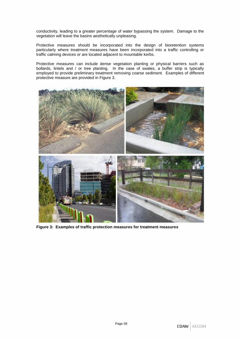
Page 59
conductivity, leading to a greater percentage of water bypassing the system. Damage to the vegetation will leave the basins aesthetically unpleasing. Protective measures should be incorporated into the design of bioretention systems particularly where treatment measures have been incorporated into a traffic controlling or traffic calming devices or are located adjacent to mountable kerbs. Protective measures can include dense vegetation planting or physical barriers such as bollards, lintels and / or tree planting. In the case of swales, a buffer strip is typically employed to provide preliminary treatment removing coarse sediment. Examples of different protective measure are provided in Figure 3.
Figure 3: Examples of traffic protection measures for treatment measures
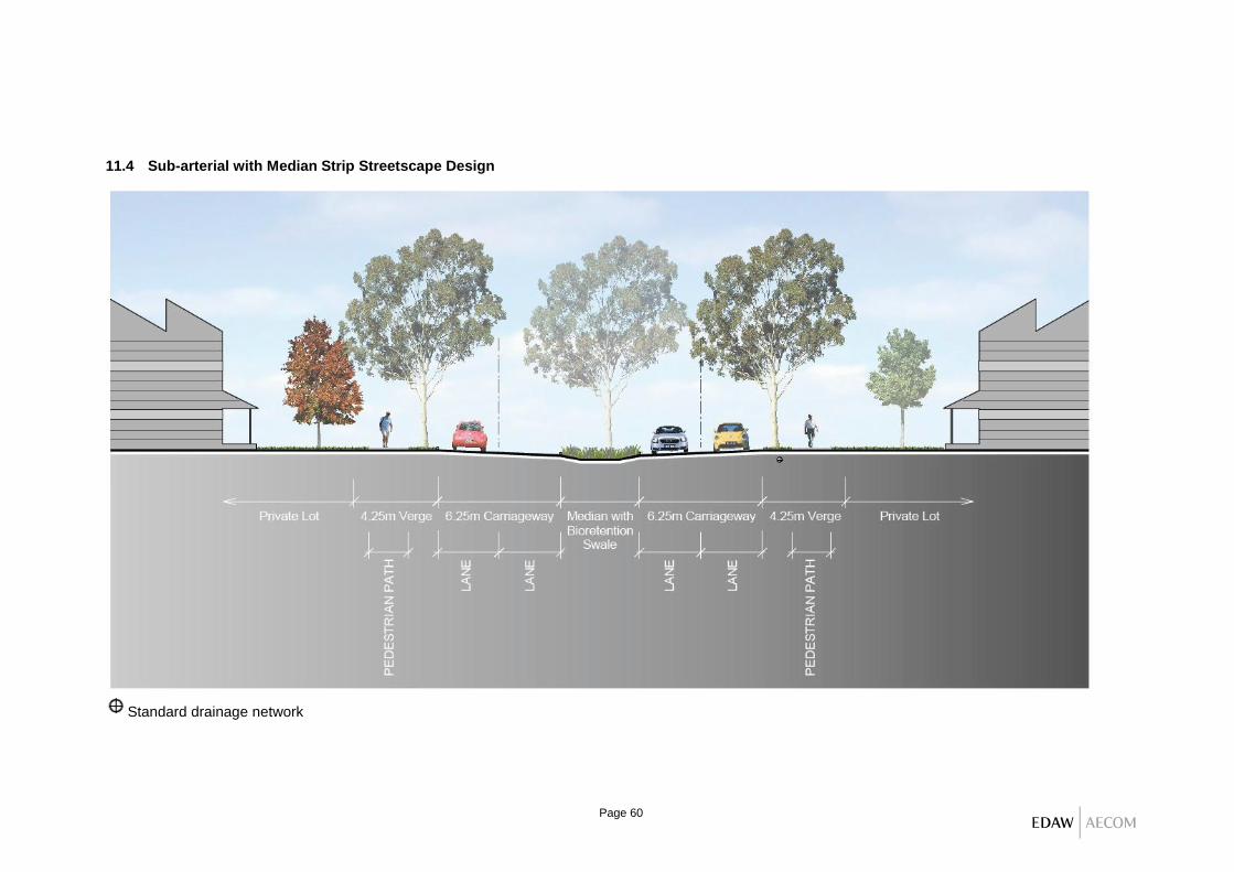
Page 60
11.4 Sub-arterial with Median Strip Streetscape Design
Standard drainage network

Page 61

Page 62
11.5 Residential Collector Streetscape Design
Standard drainage network

Page 63

Page 64
11.6 Residential Local Street Streetscape Design
Standard drainage network

Page 65

Page 66
Page intentionally left blank

Page 67
HANDBOOK PART 4: MODELLING GUIDE DRAFT JUNE 2013
12 INTRODUCTION .......................................................................................................... 68
13 MUSIC MODEL SETUP ............................................................................................... 69
14 RAINFALL AND EVAPORATION INPUTS ...... ERROR! BOOKMARK NOT DEFINED.
14.1 Rainfall Data for Water Quality Modelling ........................................................ 70
14.2 Rainfall Data for Hydrologic Modelling ............................................................. 71
14.3 Potential Evapotranspiration (PET) Data ......................................................... 72
15 SOURCE NODES AND POLLUTANT GENERATION ................................................ 73
16 RAINFALL RUNOFF PARAMETERS ......................................................................... 74
17 LINK ROUTING ............................................................................................................ 76
18 STORMWATER QUALITY TREATMENT MEASURES .............................................. 77
18.1 Wetlands .......................................................................................................... 78
18.2 Ponds ............................................................................................................... 79
18.3 Sedimentation Basins ...................................................................................... 81
18.4 Detention Basins .............................................................................................. 82
18.5 Infiltration Systems ........................................................................................... 84
18.6 Bioretention Systems ....................................................................................... 85
18.7 Media Filtration ................................................................................................ 87
18.8 Gross Pollutant Traps (GPTs) .......................................................................... 89
18.9 Buffers .............................................................................................................. 90
18.10 Swales .............................................................................................................. 90
18.11 Rainwater and StormwaterTanks .................................................................... 92
18.12 Generic Node ................................................................................................... 94
18.13 Hydrocarbons ................................................................................................... 95
19 CALCULATION OF THE STREAM EROSION INDEX ............................................... 96
19.1 How to estimate the Stream Erosion Index (SEI) ............................................ 96
19.2 Estimating the critical flow for the receiving waterway .................................... 96
19.3 Estimating the mean annual flow for pre and post-development..................... 97
19.4 Calculating SEI. ............................................................................................... 97

Page 68
12 INTRODUCTION
This section of the Blacktown Council Developer Handbook for Water Conservation, Water Quality and Waterway Stability Treatment Measures Part 4 provides guidance on the modelling of treatment measures and strategies using the Model for Urban Stormwater Improvement Conceptualisation (MUSIC). MUSIC can be used by designers, consultants, developers and Council to undertake conceptual design (size, configuration, depths) of treatment measures. Part R of the Blacktown Development Control Plan (DCP) 2006 sets out what development types require water conservation and water quality treatments and any minimum area thresholds. Where Part R applies, Blacktown City Council requires that the MUSIC model must be used to assess conceptual stormwater quality treatment and harvesting strategies, unless the development satisfies the “Deemed to Comply Solutions” from Appendix A. These guidelines are provided to ensure consultants, developers and Council have a consistent and uniform approach to stormwater quality and harvesting modelling within the Blacktown Local Government Area (LGA). The guidelines provide specific guidance on rainfall and evaporation inputs, source node selection, rainfall runoff parameters, pollutant generation parameters and treatment nodes. This Handbook is an adaptation of the Gold Coast City Council MUSIC Modelling Guidelines and should be read in conjunction with the MUSIC User Guide. The original version was produced by EDAW and AECOM based on MUSIC 3. This current version has been significantly updated to adapt to the use of MUSIC 5.1 and incorporate MUSIC modelling practises developed at Blacktown Council over a number of years following the adoption of Council’s Water Sensitive Urban and Integrated Water Cycle Management DCP Part R. These modelling guidelines apply to all of Blacktown City Council area including the growth centres and employment lands.

Page 69
Select Meterological Data Define Source Node Position relevant drainage links
Input Internal and External catchments, as described in Section 2.3
Define Catchment Area Data
Select Appropriate Meteorological Data as described in Section 2.2
Input Rainfall Runoff Parametres
Input Pollutant Parametres
Input Soil Properties as identified within Section 2.4
Select Link Routing
Run MUSIC model simulation
Input Pollutant Generation Parametres as specified in Section 2.5
Input Link Routing as identified within Section 2.6
Select Rainfall and Evaporation Data and Time Step
Screen Solutions
Develop Appropriate Treatment Train
Refer to Section 2.7 for assistance
Input Conceptual Treatment Design Parameters
Run MUSIC model simulation and compare results with water quality objectives
Not Achieve
d
Achieved
Prepare Conceptual Stormwater Management Plan
Open MUSIC
13 MUSIC MODEL SETUP
There are several steps to be undertaken prior to running a MUSIC model network, as summarised in Figure 1. These steps include selecting the appropriate meteorological data (rainfall and evaporation inputs), defining catchment areas (source nodes) to be incorporated into the model, and inputting soil properties (rainfall runoff properties) and pollutant generation characteristics for selected source nodes. Figure 8: Schematic of MUSIC modelling process (as adapted from the Gold Coast City Council MUSIC Guidelines)

Page 70
14 RAINFALL AND EVAPORATION INPUTS
Blacktown rainfall is typically 700 to 900 millimetres per year, with maximum rainfall in summer and minimum in winter. Stormwater runoff (represented as surface runoff and baseflow) is generated in MUSIC through the interaction of rainfall, evapotranspiration and the MUSIC Rainfall-Runoff Model (see MUSIC User Guide for a full description of Rainfall-Runoff Model). The following sections outline Blacktown City Council’s preferred rainfall and evapotranspiration datasets.
14.1 Rainfall Data for Water Quality Modelling Blacktown City Council requires the following approach to rainfall simulation be adopted for modelling:
Continuous simulation of a minimum of 10 years should be used.
A 6 minute time step should be used to allow for the appropriate definition of storm hydrograph movement through small-scale treatment measures such as vegetated swales and bioretention systems.
To provide a consistent approach to modelling, Blacktown City Council has identified an appropriate rainfall station for the Blacktown LGA, and periods of modelling to be utilised within the MUSIC model. Two 6 minute data stations were investigated for their suitability. These were the rainfall stations at:
067033 Richmond RAAF Base, located approximately 8 kilometres north-west of Blacktown LGA.
067035 Liverpool (Whitlam Centre), located approximately 11 kilometres south of Blacktown LGA.
Rainfall data from each of these stations was compared to daily data available at Blacktown (gauge no. 067059), to see which bore a closer resemblance to rainfall conditions within the Blacktown LGA. A common period was compared for all stations: 1964 to 1992. The results of this investigation are shown in figure 2.
Figure 2: 6 minute rainfall station comparison
0.0
20.0
40.0
60.0
80.0
100.0
120.0
Jan Feb Mar Apr May Jun Jul Aug Sep Oct Nov Dec
Month
Avera
ge r
ain
fall
(m
m)
0.0
2.0
4.0
6.0
8.0
10.0
12.0
14.0
Avera
ge n
um
ber
of
rain
days
Rainfall - Liverpool Rainfall - Richmond Rainfall - Blacktown Rain days - Liverpool Rain days - Richmond Rain days - Blacktown

Page 71
The recommended 6 minute rainfall station for use within Blacktown LGA is 067035 Liverpool (Whitlam Centre). Both the Liverpool and Richmond stations provide a reasonable match to Blacktown in terms of average monthly rainfall, but the Liverpool data matches Blacktown’s rainday pattern better than the Richmond data. A reasonable length of record is available from Liverpool, with 6 minute records starting in 1965 and continuing to 2001 (with one significant gap during 1978 to 1980). In 2001 the station was closed, but was replaced with Station 067020 Liverpool (Michael Wenden Centre). To ensure a continuous data set, data from both stations will need to be used. Given the above, Blacktown City Council requires all stormwater quality modelling in MUSIC to be undertaken using the Liverpool 6 minute rainfall data. A modelling period of 1967 to 1976 is recommended, as for this period, the annual rainfall is representative of the long-term average. Table 1 includes details of the recommended data. Table 1: Recommended 6 Minute Rainfall Station
Rainfall station Modelling period Annual rainfall (milllimetres)
067035 Liverpool (Whitlam Centre) 1967 to 1976 857
14.2 Rainfall Data for Hydrologic Modelling Blacktown City Council requires the following approach to rainfall simulation be adopted for hydrologic assessment modelling (that is, stormwater harvesting and stormwater storage design including rainwater tank sizing on a catchment basis):
Continuous simulation of a minimum of 20 years should be used.
A daily time step should be utilised for simulating rainwater/stormwater storage sizes and estimating supply reliability.
A number of daily rainfall stations were investigated for use, as shown in Table 2. The gauges investigated were those with longer available records. Table 2: Selected daily rainfall gauges in Blacktown LGA
Station Approximate location in the LGA
Data availability
Mean annual rainfall (millimetres)
Mean number of days per year with equal to or greater than 1 millimetre rain
067059 Blacktown Central 1963 to 1993 854 84
067076 Quakers Hill Treatment Works
Central 1948 to date 851 77
067016 Minchinbury South west 1901 to 1970 778 59
067026 Seven Hills (Collins Street)
East 1950 to date 926 86
To provide a consistent approach to modelling, Blacktown City Council has identified 2 appropriate daily rainfall stations for Blacktown LGA and periods of modelling to be utilised within the MUSIC model. The preferred station is 067059 Blacktown, due to its longer record of good quality data (1963 to 1993; 30 years), however 067076 Quakers Hill Treatment Works is also acceptable, for the years specified, due to its location within the catchment. The 1971 to 1992 period has been recommended to avoid significant gaps in the data. The recommended daily rainfall stations are shown in Table 3. For sub-daily simulation the Liverpool rainfall station must be used, however Liverpool is not recommended for daily

Page 72
simulation, as there is a gap in the data from 1978 to 1981 and the 1981 to 2001 period (the longest unbroken period of record available) has a relatively low average annual rainfall. Minchinbury and Seven Hills gauges are not recommended as they exhibit average rainfall conditions somewhat different to those recorded at Blacktown. Table 3: Recommended daily rainfall station
Rainfall station Modelling period Mean annual rainfall (milllimetres)
067059 Blacktown (preferred) 1963-1993 854
067076 Quakers Hill Treatment Works
1971-1992 832
14.3 Potential Evapotranspiration (PET) Data Blacktown City Council requires the following when considering potential evapotranspiration (PET) data in MUSIC:
Local PET information is preferred (where available).
In most cases, local data will not be available in which case average monthly data from Sydney (available within the MUSIC model) can be used.
Average Sydney PET data is suitable for use in modelling water quality and hydrology. The monthly PET values for the Sydney region, including Blacktown, are shown in table 4.
Table 4: Monthly evapotranspiration for the Sydney region
Month Jan Feb Mar Apr May Jun July Aug Sept Oct Nov Dec
PET millimetres
180 135 128 85 58 43 43 58 88 127 152 163
Evaporative loss should normally range from 75 per cent of PET for completely open water to
125 per cent of PET for heavily vegetated water bodies.
14.4 Electronic Modelling Council is able to supply the Liverpool (Whitlam Centre) rainfall data and evapotranspiration data electronically upon request. This MUSIC file also includes the Source Nodes and some Treatment Nodes acceptable to Blacktown.

Page 73
15 SOURCE NODES AND POLLUTANT GENERATION
Once the meteorological data has been input into the model the user must then define the source nodes to reflect the details (that is, area and landuse) of the contributing catchments. MUSIC currently has five standard land uses, these being:
Urban.
Agricultural.
Forest.
User Defined.
Imported Data. These five source nodes are however not commonly used in the Blacktown LGA. The main exception is “Forest” that can only be utilised where there is a permanent forested conservation area and its use will need to be justified for the particular scenario. Instead for Blacktown the “Urban” node is broken down into four components.
Roof.
Road.
Other Impervious Areas.
Pervious Areas. As outlined in the MUSIC User Guide, a comprehensive review of stormwater quality in urban catchments was undertaken by Duncan (1999) and this review forms the basis for the default values of event mean concentrations in MUSIC for TSS, TP and TN. More recently, Fletcher et al (2004) has updated the values provided in Duncan (1999) and specifically provides guidance on appropriate land type breakdown. Table 5 presents the recommended model defaults for various land use categories. These values are consistent with those recommended by the Growth Centres Commission (GCC). Note that for all simulations the MUSIC model must be run with pollutant export estimation method set to “stochastic generated”. Table 5: Stormwater water quality parameters for MUSIC source nodes
Land-use category
Log10 TSS (milligrams per litre)
Log10 TP (milligrams per litre)
Log10 TN (milligrams per litre)
Storm flow
Base flow*
Storm flow
Base flow*
Storm flow
Base flow*
Roof Areas Mean Std Dev
1.30 0.32
1.20 0.17
-0.89 0.25
-0.85 0.19
0.30 0.19
0.11 0.12
Road Areas Mean Std Dev
2.43 0.32
1.20 0.17
-0.30 0.25
-0.85 0.19
0.34 0.19
0.11 0.12
Other Impervious Areas
Mean Std Dev
2.15 0.32
1.20 0.17
-0.60 0.25
-0.85 0.19
0.30 0.19
0.11 0.12
Pervious Areas
Mean Std Dev
2.15 0.32
1.20 0.17
-0.60 0.25
-0.85 0.19
0.30 0.19
0.11 0.12
* Base flows are only generated from pervious areas; therefore, these parameters are not relevant to impervious areas

Page 74
16 RAINFALL RUNOFF PARAMETERS
As outlined in Section 4, stormwater runoff (represented as storm flow and baseflow) is generated in MUSIC through the interaction of rainfall, evapotranspiration and the MUSIC Rainfall-Runoff Model. A full description of the MUSIC Rainfall-Runoff Model is provided in the MUSIC User Guide. If the reader of this Handbook has no MUSIC modelling experience they should review MUSIC User Guide before reading further. MUSIC rainfall-runoff parameters have been derived for the Western Sydney region from model calibration studies. The parameters recommended in Table 6 are the same as those recommended by the Growth Centres Commission (GCC) for use in GCC areas. The GCC recommends adoption of these parameters, but also suggests that a sanity check can be performed on total runoff volumes by comparing with the values presented in Figure 2.3 of the CRC-CH’s Technical Report 04/8 (Stormwater Flow and Quality, and the Effectiveness of Non-proprietary Stormwater Treatment Measures – A Review and Gap Analysis, Fletcher et. al., 2004). Table 6: Rainfall-runoff parameters
Parameter Recommended values
Rainfall Threshold (millimetres) 1.4
Soil Capacity (millimetres) 170
Initial Storage (per cent) 30
Field Capacity (millimetres) 70
Infiltration Capacity Coefficient a 210
Infiltration Capacity Coefficient b 4.7
Initial Depth (millimetres) 10
Daily Recharge Rate (per cent) 50
Daily Baseflow Rate (per cent) 4
Deep Seepage (per cent) 0
The steps for setting up the rainfall runoff parameters are described below. Step 1: Estimate Fraction Impervious An initial estimate of the impervious fraction for the particular landuse should be made. The impervious area should be based on building density controls developed by Blacktown City Council as well as the development’s urban planners and architects. The building density controls that are of relevance include minimum soft landscaping area, maximum building envelopes, floor space ratios and road design guidelines. These estimates should also be compared to aerial photos of similar recent developments in the vicinity of the proposed development. Where differences between the estimates and the on ground impervious area are significant then estimates should be revised or the differences justified. As a guide, the fraction impervious for the different development types described in Table 3.3 of the Blacktown City Council Engineering Guide for Development (2005) are:
Public recreation areas - 50 per cent.
New residential lot only - 80 per cent.
Medium density development (villas etc) - 85 per cent.
Half width Road Reserve - 95 per cent.

Page 75
Industrial areas / commercial areas - 100 per cent.
The above fraction impervious percentage for lots applies to areas outside the growth centres. In the growth centres new residential lots are considered as 85 per cent impervious. Where landscape areas are over below ground garages, podiums, or basements, consider the area 100 % impervious. Step 2: Split MUSIC Catchments into Land Use Types The catchment must be split into the various land types (that is, roads, roofs, other impervious and pervious surfaces). Each individual source node, with the exception of the Imported Data Node, requires the total area and impervious percentage of the site to be defined. For a specific development, the site area is to be split into the four landuse source nodes from section 4. For new subdivisions calculate the area of new roads and the area of new lots. The lots can be agglomerated into the four source nodes upstream of the treatment devices. For low density residential subdivisions outside the growth centres allow the following percentages for land use for the new lots only, considering 80 per cent impervious:
Roof - 55 per cent (of which a maximum of 50% goes to the rainwater tank).
Road (driveways) - 10 per cent.
Other Impervious Areas (courtyards, paths) - 15 per cent.
Pervious Areas - 20 per cent.
For low density residential subdivisions within the growth centres allow the following percentages for land use for the new lots only, considering 85 per cent impervious:
Roof - 55 per cent (of which a maximum of 50% goes to the rainwater tank).
Road (driveways) - 10 per cent.
Other Impervious Areas (courtyards, paths) - 20 per cent.
Pervious Areas - 15 per cent.
When utilising this approach:
Roof areas are to be modelled as 100 per cent impervious. If there is a rainwater tank then it should be modelled immediately downstream of the roof. If only a portion of the roof drains to the rainwater tank, then the roof will need to be split into two separate nodes, one of which bypasses the rainwater tank. Generally Council will only consider a maximum of 50% of the roof area of residential developments draining to the rainwater tank unless there is specific information that provides a different figure when considering a specific development. In such cases the roof areas must match with the BASIX certificate for residential development.
Roads, driveways, car parks and other areas open to vehicular traffic should be modelled with all the impervious area in the “Roads” node. Any pervious areas (for example, verges) associated with impervious areas such as roads and car parks should be included in the “Pervious areas” node. Future Council roads however may be considered with the Roads node as 95% impervious and 5% pervious.

Page 76
The “Other impervious areas” node should include areas such as footpaths, courtyards and decks (including timber decks).
All pervious areas should be included in the “Pervious areas” node. Pervious areas should be directly connected to the treatment systems. The area of the treatment device itself such as for a bioretention basin, swale, or wetland also needs to be included as a pervious source node.
The MUSIC model must account for all the areas being developed. Where areas cannot drain to a treatment device these areas are considered as bypass and the specific land use(s) identified.
Step 3: Set Soil Properties For impervious source nodes, the only rainfall-runoff parameter that plays a part is the rainfall threshold, which should be set to 1.4 millimetres. For all pervious source nodes, the soil characteristics shown in Table 6 should be adopted in MUSIC. For all treatment nodes the Exfiltration Rate (mm/hr) is to be set to zero.
17 LINK ROUTING
Drainage links are used in MUSIC to connect source nodes to treatment nodes and / or collection points. The drainage links account for the passage of stormwater and the time of travel between 2 nodes. There are 3 options for the routing of stormwater available within the drainage link:
No routing.
Translation of the flood wave (only).
Muskingum Cunge method of stream routing. For single lots and subdivision developments with only a small number of lots no routing is required. For larger subdivisions the applicant may choose not to apply routing to reduce the complexity of the generated model, however, it is noted that this will result in the performance of the treatment measures being underestimated as peak inflows into the treatment nodes will increase. For MUSIC model simulations of large catchments where routing is to be undertaken it is recommended that the translation routing option in MUSIC be used to reflect the travel time for flood wave propagation through the catchment. The user is referred to the MUSIC User Guide for further details.

Page 77
18 STORMWATER QUALITY TREATMENT MEASURES
Following the determination of the site’s water quality and hydrologic objectives the user (if required) is to develop an appropriate treatment train for the development dependent on site constraints and opportunities. Within the current version of MUSIC the user has several treatment options available:
Wetland.
Pond.
Sedimentation Basin.
Detention Basin
Infiltration System.
Bioretention.
Media Filtration.
GPT.
Buffer.
Swale
Rainwater Tank.
Generic Node.
Figure 3: Treatment options available in MUSIC
The default parameters in MUSIC for the first order decay k-C* model used to define the treatment efficiency of each treatment measure should be used unless local relevant treatment performance monitoring can be used as reasonable justification for modification of the default parameters. Reference should be made to the MUSIC User Guide (2005, or subsequent versions). Note: The following measures are not to be modelled in MUSIC: natural waterways, natural wetlands, naturalised channel systems, trunk drainage, environmental buffers and ornamental lake / pond systems. In order to reduce the confusion of conflicting aspects of treatment node implementation Blacktown City Council provides the following advice for modelling stormwater quality treatment systems within Blacktown LGA. MUSIC gives the option under the “More” tab to access the “Advanced Properties” for each treatment nodes to k-C* values, orifice discharge and weir coefficients, void ratio and number of CSTR cells. Council does not permit these MUSIC default values to be changed. For residential developments Council does not permit treatment devices to be located in private courtyards or rear yards. They must be positioned in common areas, or front yards.

Page 78
18.1 Wetlands Constructed wetland systems use enhanced sedimentation, fine filtration and pollutant uptake processes to remove pollutants from stormwater. Constructed wetland systems consist of an inlet zone (sediment basin to remove coarse sediments), a macrophyte zone (a shallow heavily vegetated area to remove fine particulates and uptake of soluble pollutants) and a high flow bypass channel from the inlet pond (to protect the macrophyte zone). Provide a deeper water zone typically 1.8 m deep and absolute maximum 2.0 m deep. Wetlands are suitable downstream of pre-treatment measures such as swales, sediment basins, or GPTs designed to remove coarse sediment.
Input the appropriate bypass characteristics to reduce the impacts on macrophytes within the wetland. The high flow bypass flowrate should be set to the peak 1 year ARI flowrate.
Estimate the inlet pond volume based on a surface area of 10 per cent of the macrophyte zone surface area, and a maximum depth of 1.8 metres with batters.
Enter the proposed surface area of wetland macrophyte zone under “Storage Properties”. Note that the surface area is the figure that when multiplied by the Extended Detention Depth will give the volume of Storage. Where the sides of the basin are battered the Surface Area is the area at half the Extended Detention Depth i.e. the average basin area.
Set extended detention depth of between 0.25 to 0.75 metres. Note that any flood storage above the extended detention depth must not be included in the extended detention depth.
Set the permanent pool volume as the volume of water permanently submerging macrophytes. Set by multiplying the average depth (typically 0.25 metres to 0.4 metres) by the surface area.
Exfiltration is the water lost from the treatment measure into the surrounding soil (Council requires 0 millimetres per hour for wetlands, which should have a liner or 300 mm of compacted clay under to retain water).
Adjust the Equivalent Pipe Diameter to ensure the treatment measure has a notional detention time of approximately 48 to preferably 72 hours. This is assumed to be at the Extended Detention Depth.
Figure 4: Example of properties of a
Wetland in MUSIC

Page 79
Tick “Use Custom Outflow and Storage Relationship” where there is significant non linearity in the storage i.e. major variations in height versus area.
Other design considerations for wetlands include:
Provide an internal wall system to increase residence time and avoid short circuiting.
Provide concrete vehicular maintenance access to the basin at a maximum 10 % grade.
When designing a wetland within a detention basin, the outlet control structure of the detention basin should be placed at the end of the wetland high flow bypass channel. This ensures flood flows as ‘backwater’ across the wetland thus protecting the macrophyte vegetation from scour by high velocity flows. The detention node will be positioned downstream of the wetland node in MUSIC.
Allow for an internal drainage system that will allow for the permanent pool and remainder of wetland to be totally drained for maintenance.
Allow for various water level controls to better control the operation of the wetland particularly during establishment.
Provide macrophyte zones at varying depths to allow planting of a diverse range of plant species typically from 0.25 to 0.5 m.
18.2 Ponds Ponds can be sized for three different purposes:
Pollutant removal.
Stormwater storage for reuse.
Ornamental. For the former two purposes, MUSIC can be used to size the pond and assess its performance as described following. All ponds, though, should be preceded by appropriate pre-treatment to remove coarse sediment. Water Quality Ponds Water Quality ponds rely on settling of suspended solids as the principal treatment mechanism. Vegetation (including submerged macrophytes in a deep pond) can promote nutrient removal, and open water can promote ultra violet (UV) disinfection, however these processes are not currently able to be modelled in MUSIC. Pre-treatment is essential upstream of ponds. In MUSIC, the pollutant removal parameters associated with ponds are based on an assumption that pre-treatment has occurred upstream, and therefore it is essential to include an appropriate treatment train upstream of a pond in the MUSIC model. This could include a swale, sedimentation basin, or a suitable GPT, capable of removing a substantial proportion of coarse suspended solids.

Page 80
Input parameters include:
Identify any high flow or low flow bypasses proposed for the treatment measure.
Input the surface area of the pond. Note that the surface area is the figure that when multiplied by the Extended Detention Depth will give the volume of Storage. Where the sides of the basin are battered the Surface Area is the area at half the Extended Detention Depth i.e. the average basin area.
The extended detention depth is the depth between the top of the permanent pool and the lip of the overflow weir. Typically 0.25 to 01.0 m.
Estimate the permanent volume of water within the treatment measure.
Exfiltration is the water lost from the treatment measure into the surrounding soil (Council requires 0 millimetres per hour for ponds, which should be lined, or 300 mm of compacted clay under to retain water).
Evaporative loss as % of PET - allow 75% for open water bodies with little to no vegetation.
Modify the discharge pipe diameter to ensure a detention time long enough to allow settling of the target particle size. This is assumed to be at the Extended Detention Depth.
Tick “Use Custom Outflow and Storage Relationship” where there is significant non linearity in the storage i.e. major variations in height versus area
Storage ponds If a pond is used to store treated stormwater for reuse, its performance in balancing supplies and demands can be modelled using MUSIC. In this case, the pond may or may not be modelled with extended detention. The permanent pool actually represents the volume available for reuse, and the quantity of water is likely to fluctuate widely depending on supplies and demands.
If a storage pond has a permanent pool below the volume available for reuse, this permanent pool should be ignored.
Figure 5: Example of properties for a Pond in MUSIC
Figure 6: Example of properties for Reuse in a Pond in MUSIC

Page 81
Input parameters are as for above, but add:
Enter Re-use details to represent the intended demands on water from the storage pond.
The effectiveness of the pond as a storage system with reuse can be evaluated by checking the node water balance of the pond node once the model has run.
18.3 Sedimentation Basins Sediment basins are used to retain coarse sediments from runoff. They operate by reducing flow velocities and encouraging sediments to settle out of the water column. They are frequently used for trapping sediment in runoff during construction activities and for pre-treatment to measures such as wetlands (for example, an inlet pond). Sediment basins can drain during periods without rainfall and then fill during runoff events. Sediment basins are sized according to the design storm discharge and the target particle size for trapping (generally 0.125 millimetres). Input parameters include:
Identify any high flow or low flow bypasses proposed for the treatment measure.
Input the surface area of the basin. Note that the surface area is the figure that when multiplied by the Extended Detention Depth will give the volume of Storage. Where the sides of the basin are battered the Surface Area is the area at half the Extended Detention Depth i.e. the average basin area
The extended detention depth is the depth between the top of the permanent pool (or ground if no permanent pool) and the lip of the overflow weir.
Estimate the permanent volume of water within the treatment measure. Pool depths can be up to 2 m, but need to allow for batter slopes when calculating volumes.
Exfiltration is the water lost from the treatment measure into the surrounding soil (Council requires 0 millimetres per hour for sedimentation basins, which should be lined, or 300 mm of compacted clay under, to retain water).
Evaporative loss as % of PET - allow 75% for open water bodies.
Modify the discharge pipe diameter to ensure a detention time long enough to allow settling of the target particle size.
Figure 7: Example of properties of a Sedimentation Basin in MUSIC

Page 82
Tick “Use Custom Outflow and Storage Relationship” where there is significant non linearity in the storage i.e. major variations in height versus area
Note: This treatment measure can be utilised as pre-treatment measure upstream of a wetland or sand filter and allows for a diversion of flows above recommended scour velocities.
18.4 Detention Basins Detention basins can be above ground, or below ground in tanks. Above ground basins are favoured by Council as they are easier to maintain and avoid confined space entry and the associated risks. Council current has two approaches to detention systems. The older established areas of Blacktown LGA use a High Early Discharge (HED) system. HED directs as much of the site as possible straight to the small HED control pit which fills up and thereby reaches close to the maximum discharge quickly. Detention with HED requires a smaller storage volume than a conventional detention system. A conventional detention system is one where the discharge rate rises more slowly than with HED as the storage fills over the entire basin area. The conventional detention system is predominantly used in the growth centres. The default Detention Basin node in MUSIC is based on a conventional detention system with a single outlet. It cannot be used to represent a detention basin with a HED outlet. This needs to be represented differently in MUSIC. Where water quality treatment (e.g. bioretention, or proprietary filters or devices) is incorporated into a detention basin itself, or enlarged HED pit, the treated flow must discharge downstream of the discharge control pit to ensure ongoing treatment throughout a range of storms. This may require adjustment to the discharge controls to ensure the design discharge is maintained and account for the bypass. Council’s requirement for concrete detention tanks, or above ground detention basins with a concrete base, is for the base to have a minimum grade of 2%. This grade ensures that settled material is flushed from the system. No allowance can therefore be made for the settlement of material and consequently no reduction in TSS, TP, or TN is permitted for concrete detention tanks, or above ground basins with a concrete base. Reduction in TSS, TP or TN is only permitted for vegetated (including turfing) above ground detention basin where settled material can be trapped by the vegetation. Where vegetated above ground detention basins incorporate bioretention in the base, the area of bioretention is to be excluded from the area in detention node. Conventional Detention Basins
Input parameters include:
Identify any high flow or low flow bypasses proposed for the treatment measure.
Input the surface area of the basin. Note that the surface area is the figure that when multiplied by the Extended Detention Depth will give the volume of Storage. Where
Figure 8: Example of properties of a conventional Detention Basin in MUSIC

Page 83
the sides of the basin are battered, the Surface Area is the area at half the Extended Detention Depth i.e. the average basin area.
The extended detention depth is the depth between the average base level of the storage (generally not the centreline of the outlet pipe or orifice) and the lip of the overflow weir, or design storage level.
Evaporative loss as % of PET - allow 0% for tanks and 75% for above ground detention systems.
Exfiltration is the water lost from the treatment measure into the surrounding soil (Council requires 0 millimetres per hour for detention basins, which should be concrete, or on a compacted clay base, or lined to retain water).
The Low Flow Pipe discharge rate will be initially determined from the detention calculations. Using this discharge a nominal orifice size (low flow pipe diameter) is calculated using the extended detention depth from above and not the actual depth to the orifice or pipe centreline.
Tick the “Use Custom Outflow and Storage” box for more complex, or multiple basin discharges with the option of importing a discharge spreadsheet where required. This method should be utilised for landscaped above ground basins with uneven base levels and/or batter slopes to better represent the settlement of pollutants over smaller surface areas in more frequent storm events.
Where a detention node is used for a concrete tank, or an above ground detention basin with a concrete base then, click the “More” tab in MUSIC, and set the “k” values for TSS, TP and TN all to “0”. This ensures that no treatment occurs in this type of basin as settled material is flushed from the base.
High Early Discharge (HED) Configuration in MUSIC The HED discharge control pit has no silt trap in accordance with Council requirements, but contains either a Maximesh, or Weldlok screen (for orifices greater than 150mm diameter). A Generic Node is used to represent the HED pit. As there is no way to contain any pollutants that settle out in the HED pit there is no reduction in TSS, TP, or TN (they simply wash through). Gross pollutants are defined as material that would be retained by a five millimetre mesh screen. It is common not to include Gross Pollutant removal in this HED node, however where required allow 50% removal for Maximesh Screens and 10% removal for Weldlok Screens. The critical input for the HED node is the High Flow Bypass in (m
3/s). Council has
produced a spreadsheet for calculation of the on-site detention systems with HED. The spreadsheet provides a discharge rate for “High early discharge” in l/s. This is the discharge before overtopping of the weir into the extended detention storage area. To input into the node this flow needs to be converted to m
3/s.
A typical arrangement for a system with HED is detailed below in figure 9.

Page 84
Figure 9: Example of a MUSIC model The MUSIC model above is set up with the primary flow from the orifice discharging downstream to the next node. The red dashed secondary drainage link is then directed to the detention basin node. This secondary flow is set to the high flow bypass from the HED pit. The detention basin node is as set up for the conventional detention basin excluding the area of the HED pit. The Low Flow Pipe Diameter is set to the orifice size in the HED pit. As Council requires as much of the site as practical to discharge direct to the HED pit, only the area that directly falls within the above ground basin, or for a tank the area above the tank that discharges straight into the tank due to the frequent pit grates, is permitted to be directed to the detention basin node. The use of this arrangement in MUSIC will provide some assistance in achieving the water quality objectives for above ground landscaped detention basins, but will not achieve overly significant benefits. Many designers choose not to undertake this additional modelling step in smaller developments. As noted above in the introduction to section 7.4, for concrete detention tanks, or above ground basins with a concrete base, no allowance can be made for the settlement of material and consequently no reduction in TSS, TP, or TN is permitted. Similarly the use of the HED generic node and secondary bypass to the detention node as a modelling approach has limited application for concrete detention tanks, or above ground basins with a concrete base. The only benefit in undertaking this additional modelling step is where the water quality treatment device is downstream of the detention and the reduction in flow rates through this node provides improved performance of this water quality device. Otherwise it is not required.
18.5 Infiltration Systems Infiltration measures encourage stormwater to infiltrate into surrounding soils. Infiltration measures are highly dependent on local soil characteristics and are best suited to sandy soils with deep groundwater. Infiltration is not recommended in areas of sodic or saline soils or soil contamination, where infiltration could mobilise salts or contaminants. Given the presence of

Page 85
clay throughout the LGA as well as significant areas of sodic and saline soils, infiltration will not be permitted in the Blacktown LGA.
18.6 Bioretention Systems Bioretention systems are a combination of vegetation and filter substrate that provides treatment of stormwater through filtration, extended detention and some biological uptake. The systems are designed to accept stormwater runoff and allow it to percolate through the filtration media. At the base of the filter media, treated stormwater is collected within a drainage layer comprising a system of perforated pipes laid in gravel, to ensure the treatment measures are drained adequately. Bioretention systems need to be densely planted out with sedges and shrubs to help maintain the conductivity of the filter media, promote nutrient removal, and create an attractive landscaped form/feature. Large shrubs and some trees are permitted subjected to larger filter media thicknesses. See also Handbook 5 for allowable plant species.
Figure 10: Example of properties of a Bioretention System in MUSIC
Input parameters include:
Identify whether a bypass structure shall be included within or upstream of the treatment measure to control flows.
Identify the Extended Detention Depth (ponding depth) in metres prior to overflowing the control weir of the treatment measure. The maximum Extended Detention Depth is 0.4 metres for Blacktown generally, however for public basins within

Page 86
Council property the maximum Extended Detention Depth is 0.3 metres. Where a bioretention swale is proposed the Extended Detention Depth is set to zero.
Provide the Surface Area (m2) of the treatment measure based upon site constraints.
Note that the surface area is the figure that when multiplied by the Extended Detention Depth will give the volume of Storage. Where the sides of the basin are battered the Surface Area is the area at half the Extended Detention Depth i.e. the average basin area.
Filter Area (m) is the area of bioretention filter media available for planting and excludes the areas of pits, sediment traps, steps and scour protection.
Unlined Filter Media Perimeter (m) is set to 0.1 m. (Filter is fully lined).
The filter media is a sandy-loam mixture designed to provide adequate organic material for vegetation/root growth yet still ensure sufficient flow through drainage characteristics. A typical rate of Saturated Hydraulic Conductivity is 100 millimetres per hour. The maximum Saturated Hydraulic Conductivity permitted in Blacktown is 125 millimetres per hour. (Note Council requires certification from the filter media supplier that that the bioretention filter media has a minimum hydraulic conductivity as defined by ASTM F1815-06 (actual, not predicted) of twice the rate specified in MUSIC.)
Provide the proposed depth of filter media in metres within the treatment measure. The minimum Filter Depth is 0.4 metres for Blacktown. The following depths are recommended as a minimum within the treatment measure: 0.4 metres for sedges and small shrubs and up to 0.8 metres for tree species. This will ensure adequate area for root growth is provided within the treatment measure. This depth does not include the transition layer, or drainage layer. See also Handbook 5 for minimum depths for specific plant species.
TN Content of Filter Media (mg/kg) – Blacktown requires 800 mg/kg.
Orthophosphate Content of Filter Media (mg/kg) - Blacktown requires 40 mg/kg.
Exfiltration is the water lost from the treatment measure into the surrounding soil (Council requires 0 mm/hr for bioretention basins, which should be lined to retain water).
Is Base Lined? – tick “Yes”
Vegetation Properties. Highlight “Vegetated with Effective Nutrient Removal Plants”. See Handbook 5 for specific plant species. Grass is not acceptable.
Overflow Weir Width (metres) – as per design.
Underdrain Present? – Tick “Yes” (Council requires unsocked PSC slotted pipes within the drainage layer.
Submerged Zone with Carbon Present? – Tick “No”. Blacktown does not permit submerged or saturated zones for bioretention.
The default k-C* values for the bioretention system must not be adjusted without prior approval from Blacktown City Council.

Page 87
Additional Design Information for Bioretention Systems
The bioretention system is to be encased in a low permeability compacted clay (typically 300 mm), in an HDPE liner, or other approved liner.
The invert levels of all pipes discharging to the bioretention system must be above the top of the filter media. Surcharge pits are not permitted.
Where bioretention is incorporated as part of a detention basin the subsoil drainage must discharge downstream of the discharge control pit to ensure ongoing treatment through a range of storms.
Note that where bioretention basins are incorporated as part of an on-site detention system the detention basin storage must exclude the Extended Detention Depth of the bioretention.
Bioretention systems are very vulnerable to sediment loading and must be protected by pre-treating discharges to remove as much sediment as possible. A silt arrestor pit with screen, or a proprietary gross pollutant trap (GPT) is required upstream. Pipe diameters 375 mm or greater must provide a proprietary GPT, but it is also preferred for smaller pipe sizes such as 300 mm diameter, or even 225 mm. Council will accept a MUSIC node for a proprietary GPT (where the device is approved for use in Blacktown), but not for the default silt arrestor pit. Minimum silt arrestor pit sizes are detailed below.
Outlet Pipe Diameter (mm)
Pit Dimensions (mm) Screen Type Minimum Silt Trap Depth (mm)
100 600 x 600 Maximesh Rh3030
300
150 900 x 900 Maximesh Rh3030
400
225 1200 x 1200 Weldlok F40/203
400
300 (max) 2100 x 2100 Weldlok F40/203
400
Table 7: Silt Arrestor Pit Size and Configuration for Pre-treating Bioretention Systems
18.7 Media Filtration Media filtration usually refers to sand filters that treat stormwater via infiltration through a soil or sand media. Sand filters, unlike bioretention systems, are not vegetated, are often constructed in tanks underground and can be constructed with much higher filtration rates. Due to the fact that sand filters are not vegetated, they can be prone to clogging unless adequate pre-treatment is provided upstream of the sand filter. They can also be maintenance intensive. Sediment removal is particularly important to minimise the risk of clogging, and it is recommended that pre-treatment should meet the target for a minimum of 70 per cent removal of the TSS load. Sand filters must be constructed of fine to fine/medium sand, or sandy loam. Coarse sand, or fine gravel materials are not permitted as the top layer for Media Filtration in Blacktown as they will not remove a significant pollutant load. It is common to use the same media in the top layer as for bioretention.

Page 88
Media filtration should contain a number of common elements.
The media filtration system must include a sedimentation basin upstream of the filter as a node in MUSIC. See section 7.3. This basin is designed to capture a minimum 85% of 125 µm particle size, or larger.
The sedimentation basin must include a high flow bypass set to the 1 year flow or less with a baffle to retain oils and floatables.
The media filter material should be free of fines and have a relatively uniform grain size distribution.
Energy dissipaters and flow spreading is required to minimise scour prior to discharge to the filter media.
System will include a transition layer and drainage layer.
Frequent safe access is required for maintenance for the raking or replacement of sand. This is a major consideration with confined space entry into a tank.
Input Parameters into the MUSIC node include:
Identify any high flow or low flow bypasses proposed for the treatment measure.
Identify the ponding depth of stormwater runoff prior to its overflowing the control weir of the treatment measure (extended detention depth).
Provide the estimated surface area (m2) of the storage. Most sand filters in tanks will
have vertical sides and the area will match the filter area, however where the sides of the basin are battered the Surface Area is the area at half the Extended Detention Depth i.e. the average basin area for storage.
Exfiltration is the water lost from the treatment measure into the surrounding soil (Council requires 0 mm/hr for media filtration basins, which should be lined or within a concrete tank to retain water).
Input the surface area of the filter media (m
2) within the treatment measure.
Provide the proposed depth of filter media (m) within the treatment measure. This depth does not include the transition or drainage layer. Minimum is 0.2 m, but 0.4 to 0.6 m is typical.
Identify the type of filter media proposed based upon Filter Median Particle Size (mm) and Saturated Hydraulic Conductivity (mm/hr). See examples in Table 7. The maximum Saturated Hydraulic Conductivity for a sand media filter in Blacktown is 600 mm/hr. (Note Council
Figure 11: Example of properties of Media Filtration in MUSIC

Page 89
requires certification from the filter media supplier, or engineer that that the filter media has a minimum hydraulic conductivity as defined by ASTM F1815-06 (actual, not predicted) of twice the rate specified in MUSIC.).
Soil Type Median Particle Size (mm)
Saturated Hydraulic Conductivity (mm/hr)
Sand 0.7 300
Sandy loam 0.45 125 Table 7 : Typical Filter Median Particle Size and Saturated Hydraulic Conductivity
The depth below underdrain pipe should normally be zero. This parameter is only relevant when the filter media extends below the slotted drainage pipe.
18.8 Gross Pollutant Traps (GPTs) GPTs typically remove rubbish and debris, and can also remove sediment and hydrocarbons from stormwater runoff. These treatment measures can be very effective in the removal of solids conveyed within stormwater which are typically larger than 5 millimetres in size. Some devices are capable of removing finer sediments. Many devices will not remove any TSS, TP or TN. All proprietary GPT nodes have to be pre-approved by Blacktown City Council. Council currently has MUSIC nodes available for a range of devices and designers need to contact Council to obtain them. These nodes will set the removal rates for the pollutants within MUSIC. The only Input parameter is:
Calculate the required high flow bypass for the site (often the 3 or 6 month ARI peak flow). Match this flow with the nearest appropriately sized approved proprietary device, or the upstream diversionary weir to the GPT. In some cases the allowable flow through the device approved by Council may be less than that claimed by the manufacturer.
Vortex-type GPTs have been shown to remove some TSS and TP. For further information see Appendix C of the MUSIC User Guide. Vortex-type GPTs have TSS removal up to 70 per cent for inflow concentrations greater than 75 milligrams per litre. TP removal can be up to 30 per cent for inflow concentrations greater than 0.5 milligrams per litre. TN removal should be left at zero. Other approved devices will have varying removal rates. Check with Council. GPTs must have the ability to retain free oil, unless alternate specific hydrocarbon removal measures are undertaken. Figure 12: Example of TSS removal in a
Vortex style CDS unit in MUSIC

Page 90
18.9 Buffers Buffer or filter strips, in the context of urban stormwater, are grassed or vegetated areas over which stormwater runoff from adjoining impervious catchments traverses en route to the stormwater drainage system or receiving environment. Buffer strips are intended to provide discontinuity between impervious surfaces and the drainage system. They take water from impervious surfaces in a distributed manner, promote even flows and filter sediments and coarse pollutants entrained in the runoff. The key to their operation is an even shallow flow over a wide vegetated area. Utilise buffer treatment measures upstream of other treatment measures to assist in sediment drop out prior to stormwater entering secondary treatment measures such as swales. Distributed flows and a shallow grade (1 to 5 per cent) are essential. The low hydraulic loading over the vegetation allows flows to filter through the vegetation and pollutants to settle out. They also provide a detention role to slow flows down. Where grades exceed 5%, this area is not considered as buffer and is to be excluded from the MUSIC model. Input parameters include
Calculate the percentage of upstream area that shall actually pass over buffer. This refers to the proportion of the Source Node’s impervious area which has buffer strips applied to it. For example, in a Source Node with 20 ha of impervious area, 16 ha (or 80%) may have buffer strips applied. Note that the pervious area of the source node is ignored.
Calculate the size of the proposed buffer area as a percentage of the upstream catchments impervious area. This is a measure of the actual size of buffer strips, defined as the percentage of the Source Node impervious area. The default value is 5%. This means that the total area of buffer strip is equivalent to 5% of the Source Node impervious area.
The exfiltration rate must be set to zero.
18.10 Swales Vegetated swales are open vegetated channels that can be used as an alternative stormwater conveyance system to conventional kerb and channel along roads and associated underground pipe. The interaction of surface flows with the vegetation in a swale facilitates an even distribution and slowing of flows thus encouraging particulate pollutant settlement. Swales can be incorporated into streetscape designs and can add to the aesthetic character of an area. They are also ideal as a pre-treatment measure for stormwater, particularly for coarse sediment removal. Where there are significant point loads coming in partway along the length of the bioretention swale, the swale needs to be broken up into smaller swale lengths at these points.
Figure 13: Example of Buffer properties
in MUSIC

Page 91
Standard Swale Input parameters include:
Identify the length of the swale based upon location and site constraints
Determine the longitudinal slope of the swale. Swales with bed slopes greater than 5 per cent are not recommended as treatment measures (however rock check dams can be used to design swales with steeper slopes and these can still be used as conveyance treatment measures).
Swales with bed slopes less than 1 per cent are to incorporate a gravel trench with un-socked subsoil line (the gravel trench is to be wrapped in geotextile) within the base of the treatment measure to promote adequate drainage.
Provide dimensions for the base and top width of the swale.
Calculate the depth of the treatment measure based upon the base and top width characteristics and identify the height of vegetation within the treatment measure. Vegetation heights of 0.05 to 0.3 metres are acceptable, however MUSIC assumes that swales are heavily vegetated when modelling their treatment performance. Mown grass swales should not be expected to provide significant stormwater treatment and should not be modelled in MUSIC.
Exfiltration is the water lost from the treatment measure into the surrounding soil (Council requires 0.00 mm/hr for swales).
Special Requirements for Bioretention Swales Where a bioretention swale is specified in MUSIC the requirements are as for section 7.6 Bioretention except that:
The Surface Area must match the Filter Area.
The Filter Area is calculated as the length of the bioretention swale component multiplied by the width of the filter (this needs to be level across). This ignores any other standard swales that may be further upstream and that need to be modelled separately.
The Extended Detention Depth is set to zero.
Where there are significant point loads coming in partway along the length of the bioretention swale, the swale needs to be broken up into smaller swale lengths at these points.
There are two options for MUSIC modelling. Firstly you can ignore the swale aspect altogether and simply model the bioretention component as detailed above. This is simpler and easier and commonly undertaken. The second option is that you include the bioretention and swale as two separate nodes in MUSIC.
Figure 14: Example of properties of a Swale in MUSIC

Page 92
The first node is the bioretention node as noted above (i.e. consider the bioretention filter surface by itself). The second (downstream) node is the standard swale node with a single change.
Swale characteristics are as detailed above for a standard swale ensuring the bed slope does not exceed 5%.
The only change is that a low flow bypass into the treatment measure needs to be calculated. This is the flow infiltrating through the surface of the bioretention into the underdrain pipes. This low flow bypass is calculated by the following formulae: Low Flow Bypass = BSA x ksat / (1000 x 3600) in m
3/s
Where: BSA = Bioretention surface area ksat = Saturated Hydraulic Conductivity of the filter media in mm/hr (max 125 mm/hr).
18.11 Rainwater and StormwaterTanks Rainwater tanks can serve two main purposes. Primarily, they are designed to provide an alternative source of water for non-potable uses such as irrigation, toilet flushing, laundry, hot water, or industrial process water. They are not intended, nor should they be seen as a component of detention. Rainwater tanks are to only accept runoff from a Roof source node. To design a rainwater tank for reuse involves balancing the supply and demand and selecting an appropriate tank size to meet a reasonable proportion of demand. This can be achieved in MUSIC. Rainwater tanks can also be designed to act as a treatment measure, as some settling occurs in the tank, and when rainwater is utilised, some pollutants are removed along with the water. Non-potable Reuse Rates for Modelling Rainwater Tanks in MUSIC The following rates are provided as a guide for MUSIC modelling purposes. Residential development (excluding home units or multistorey dwellings) allow for rainwater reuse per dwelling based on the area of lots as follows:
Lots > 720 m2 allow 0.14 KL/day internal use & 100 KL/year as PET- Rain
Lots > 520 & < 720 m2 allow 0.12 KL/day internal use & 75 KL/year as PET- Rain
Lots > 320 & < 520 m2 allow 0.10 KL/day internal use & 50 KL/year as PET- Rain
Lots < 320 m2 allow 0.08 KL/day internal use & 25 KL/year as PET- Rain
NOTE: Consider each Villa and/or Townhouse dwelling as Lots < 320 m
2
Industrial and commercial developments, including schools, child-care centres, hotels/motels, hospitals, halls, sporting fields and aged care and places of worship (including not-for-profits), allow for rainwater reuse as follows:
For internal rainwater reuse, allow 0.1 KL/day per toilet, or urinal in industrial/commercial developments and generally ignore any disabled toilet. However where the site is only occupied say 6 days per week the daily usage rate is to be

Page 93
proportioned by 6 / 7. Similarly where there is an additional afternoon, or night shift using less staff, increase the rate proportionally.
Other internal usage may involve vehicle washing or other industrial usage and specific data will need to be supplied to justify these reuse rates.
For irrigation of landscaped areas only allow 0.4 kL/year/m2 as PET-Rain for sprinkler
systems and 0.3 kL/year/m2 for subsurface irrigation. For bioretention filter areas only
allow 0.4 kL/year/m2 as PET-Rain (subsurface irrigation only). Higher rates may be
required by the landscape architect for specific landscape requirements, however such rates will not be accepted by Council in the MUSIC model. This does not stop the Landscape Architect increasing the rainwater tank size to cover such requirements.
First Flush Systems and Rainwater Tank Pre-Treatment As a means of improving the water quality of the stored water in a rainwater tank, it is common to remove a certain volume of runoff off the roof, referred to as the first flush, on the understanding that most of the pollutants will be contained in this runoff. This reduces the chance of thes pollutants entering the rainwater tank. Typically this may be the first one or two millimetres of runoff off the roof. These systems are then drained via a low flow or dribble pipe. In MUSIC the roof node would connect direct to a detention node to represent the properties of the first flush tank and low flow outlet. The primary flow will be directed to wherever the low flow pipe drains to and the weir overflow will be directed as secondary flow to the rainwater tank. Where a first flush system is not used, other pre-treatment is usually required for the rainwater tank typically as a screen and silt trap. Unless these are a proprietary device accepted by Council, no credit will be given in MUSIC. Specific requirements for such devices may be required in charged systems under pressure. Rainwater Tank Sizes Allow for a 20% loss in rainwater tank volume in MUSIC to allow for anaerobic zones, mains water top up levels and overflow levels. e.g. where a 10 kL tank is specified on the drainage plan it is to be modelled as 8 kL in MUSIC. For residential development the tank size is as required for BASIX. Where rainwater tank sizes are proposed by the designer are larger than those specified in BASIX, or the roof area draining to the tank varies, the BASIX certificate is to be amended to match. When assessing low density residential subdivisions allow for a rainwater tank size of 2.5 kL supplied, but modelled as 2.0 kL in MUSIC per dwelling. Also allow for a Surface Area of rainwater tank of 1.7 m
2 per dwelling.
For industrial and residential development the rainwater tank size will be determined to meet the 80% non-potable reuse requirement.
Figure 15: Example of properties of a Rainwater Tank in MUSIC

Page 94
Input parameters include:
Identify any high flow or low flow bypasses proposed for the treatment measure. Generally the default values are retained.
Input the tank volume (with 20% reduction as noted above).
The depth above overflow, can be estimated roughly or left at default values. This parameter does not have a significant influence on the results.
The surface area can be determined from available information, or roughly estimated.
The overflow pipe diameter can be estimated roughly or left at default values. This parameter does not have a significant influence on the results.
Tick “Use stored water for irrigation or other purpose”. For irrigation usage PET - Rain is recommended. It is defined as an annual demand (kL/yr) and scaled according to the daily PET value minus the daily rainfall data contained in the Meteorological Template used to create the model rainfall (i.e. when PET exceeds rainfall, reuse will occur, or more simply you don’t water the garden when it is raining.) Daily demand (kL/day) refers to more constant internal usage such as toilet flushing, laundry use, some industrial processes, or vehicle washing. Monthly distribution would only apply to a specific industrial reuse. Details of general allowable rates are indicated above.
The effectiveness of the rainwater tank at meeting the demands upon it can be evaluated by clicking on the Rainwater Tank Node after running MUSIC. Right click on “Statistics” and under “Node Water Balance” review the “% Reuse Demand Met” result in the Flow column. For residential development there is no specific reuse target as the development is subject to BASIX. For commercial and industrial development, Council requires a minimum of 80 % non-potable reuse to be met through rainwater. Residential development is subject to BASIX and has no minimum % reuse requirement for Council. An example MUSIC model setup, showing the location of a rainwater tank, was shown in figure 9. Stormwater Tank Modelling Constraints Stormwater tanks differ from rainwater tanks in that they may collect water from a variety of sources including driveways, parking areas and landscaped areas as well as rainwater tank overflows. This adversely affects the quality of water and the range of pollutants that may be captured. Some such pollutants may be adverse to public health and may include poisons used on the garden or chemicals spilt on the driveway, or parking areas. Consequently stormwater reuse is not permitted for residential development at all, nor is it permitted for toilet flushing for commercial or industrial developments. Stormwater reuse is permitted for subsurface drainage of landscaped area for commercial or industrial developments subject to a high level of filtering and any other additional treatments as required by your consultant. Stormwater reuse may also permitted for some industrial processes subject to a more detailed review and risk assessment. The characteristics of a Stormwater Tank in MUSIC is identical to that of a Rainwater Tank. The designer mainly needs to ensure that when the “Use stored water for irrigation or other purpose box” is checked, that the demands are appropriate and fit for purpose.
18.12 Generic Node This node allows the user to simulate the treatment performance of treatment measures not listed within the default parameters. The use of these nodes for specific treatment devices is not permitted without direct approval from Blacktown City Council. A range of approved Generic Nodes is available from Council for a range of existing proprietary devices.

Page 95
The use of the generic node is permitted when used for a flow transfer function without any treatment. This may be to represent a diversion weir, or as an HED pit as detailed in Figure 9. Such nodes are also used when determining the Stream Erosion Index (SEI) as detailed in section 8.
18.13 Hydrocarbons Council requires the post development average annual load reduction of 90% for Total Hydrocarbons. Hydrocarbons in water can be found as free floating, emulsified, dissolved, or adsorbed to suspended solids. A hydrocarbon, by definition, is one of a group of chemical compounds composed only of hydrogen and carbon. Microbes in the soils and water have a natural ability to breakdown many of these compounds and any hydrocarbon which is exposed to the air will also have an affinity to volatilise. As well, reactions including photochemistry and the various transformations of the hydrocarbon through these reactions, can enhance the hydrocarbon decomposition. This includes free oils and emulsified hydrocarbons. MUSIC at this time is unable to assess the removal of Total Hydrocarbons. Consequently empirical methods are required to achieve the required load reduction. To meet the 90% target for hydrocarbon removal for on-line flows, a system is to be provided capable of retaining hydrocarbons through an appropriately sized baffle system that reduces the flow velocities sufficiently to contain and store the hydrocarbons for the peak flow. To meet the 90% target for hydrocarbon removal for off-line flows, the system is to be designed to treat the six (6) month flow using a proprietary hydrocarbon removal device, or gross pollutant trap with oil baffle, or an appropriately sized baffle system that reduces the flow velocities sufficiently to contain the hydrocarbons. Industrial or commercial development with carparks, or manoeuvring areas greater than 1000 m
2 must provide a device that specifically targets the removal of hydrocarbons from the
treatment train.

Page 96
19 CALCULATION OF THE STREAM EROSION INDEX
19.1 How to estimate the Stream Erosion Index (SEI) Blacktown City Council uses the method developed in the Draft NSW MUSIC Modelling Guide (Aug 2010) that is adapted from Blackham and G. Wettenhall (2010). Water Sensitive Urban Design (WSUD) strategies are typically modelled using the Model for Urban Stormwater Improvement Conceptualisation (MUSIC). MUSIC can be used to estimate the SEI for a development’s stormwater management strategy to determine compliance with the SEI objective. Blacktown Council requires that the post development duration of stream forming flows shall be no greater than 3.5 times the pre developed duration of stream forming flows with a stretch target of 1. The Four Steps for Estimating Stream Erosion Index
1. Estimate the critical flow for the receiving waterway above which mobilisation of bed
material or shear erosion of bank material commences.
2. Develop and run a calibrated MUSIC model of the area of interest for pre-
development conditions to estimate the mean annual runoff volume above the critical
flow.
3. Develop and run a MUSIC model for the post developed scenario to estimate the
mean annual runoff volume above the critical flow.
4. Use the outputs from steps 3 and 4 to calculate the SEI for the proposed scenario.
19.2 Estimating the critical flow for the receiving waterway The critical flow for a waterway is defined as the flow threshold below which no erosion is expected to occur within the waterway. This has been estimated (EarthTech, 2005) as a percentage of the
pre-development two year ARI peak flow at the location in question. For Blacktown this percentage is 25% based on the dispersive characteristics of the typical local clay soils. The
peak flow from the two year ARI storm event corresponding for pre-developed conditions is to be calculated using the probabilistic rational method as described in Australian Rainfall and Runoff
1.
1. Using the area of the site (in km
2), calculate the Time of Concentration using the
probabilistic rational method from equation 1.4 of AR&R Volume 1, Book 4.
) ))
2. Select I2 (mm/hr) from the Rainfall Intensity Chart in the Engineering Guide for
Development based on the 2 year ARI and the calculated in minutes.
3. Determine the two year ARI runoff coefficient C2 using equation 1.5 of AR&R Volume
1, Book 4,
C2 = C10 x FF2 = 0.6 x 0.74 = 0.444
where C10 is the 10 year runoff coefficient from Fig 5.1 from AR&R Volume 2 = 60%,
and
FF2 = the 2 year frequency factor from Table 1.1 of AR&R Volume 1, Book 4 = 0.74.
4. Using the rational method Q2 = 0.278 x C2 x I2 x A, substitute results from 2 and 3
above.
Q2 (m3/s) = 0.278 x 0.444 x I2 x A = 0.1234 x I2 (mm/hr) x A (km
2)
5. Qcritical = Q2 x 25%.

Page 97
19.3 Estimating the mean annual flow for pre and post-development. The data required for estimating SEI can be directly extracted from MUSIC by interrogating a generic node that is added to the treatment train immediately upstream of the receiving waterway or in this case the receiving node. The generic node in MUSIC provides a flow transfer function which can be simply defined to easily calculate the annual volume of flow above the critical flow. The generic node should be set up to convert all inflows at, or below the critical flow to zero outflows. Flows above the critical flow will be passed through the node at the magnitude by which flow exceeds the critical flow, as described below: Qout = 0 if Qin < Qcritical Qout = Qin - Qcritical if Qout > Qcritical Two MUSIC models are to be prepared. The pre-development model shall incorporate a realistic assessment of the site impervious percentage and any natural features such as ponds or farm dams. The use of the default MUSIC source nodes for Agriculture and Forest may be applicable for some pre-development modelling. The post development MUSIC model is the same model required to meet the water quality systems targets, but with the Generic flow transfer node added. Note for some subdivisions where Generic nodes are needed to represent future on-site treatment for certain development types, an additional MUSIC model may need to be developed to reflect the use of rainwater tanks and other flow attenuating systems to ensure compliance with the Stream Erosion Index targets.
19.4 Calculating SEI. Check the flow transfer generic nodes at the downstream end of the MUSIC models for pre and post-development conditions by:
1. Right clicking the generic node
2. Clicking on ‘Statistics’ then ‘Mean Annual Load’
3. Copying the flow output value
The SEI is calculated as the ratio of the output mean annual flow from the generic node for the post-developed model over the corresponding value for the pre-development model as detailed below: SEI = ∑(Qpost – Qcritical) / ∑(Qpre – Qcritical) The SEI has to be less than 3.5 with a stretch target of 1.

Page 98
HANDBOOK PART 5: VEGETATION SELECTION GUIDE-
DRAFT 10/2012
20 INTRODUCTION .......................................................................................................... 99
21 BLACKTOWN CITY COUNCIL STREET TREE SPECIES LIST .............................. 100
22 INDICATIVE SPECIES FOR SWALE AND BUFFER STRIP PLANTING ................ 102
22.1 Turf ................................................................................................................. 102
22.2 Trees .............................................................................................................. 103
22.3 Shrubs ............................................................................................................ 103
22.4 Tufted Species ............................................................................................... 104
22.5 Ground covers ............................................................................................... 104
22.6 General Considerations ................................................................................. 104
23 INDICATIVE SPECIES FOR PLANTING IN WETLAND ZONES ...................................
23.1 Batters ............................................................................................................ 109
23.2 Ephemeral Zone ............................................................................................ 110
23.3 Shallow Marsh Zone ...................................................................................... 110
23.4 Marsh Zone .................................................................................................... 111
23.5 Deep Marsh Zone .......................................................................................... 111
23.6 Deep Water Pools .......................................................................................... 111
23.7 General Considerations ................................................................................. 112
24 INDICATIVE SPECIES FOR PLANTING IN BIORETENTION CELLS,
RAINGARDENS AND BIORETENTION SWALES ................................................... 113
24.1 Groundcovers................................................................................................. 113
24.2 Tufted Species ............................................................................................... 114
24.3 Small Shrubs .................................................................................................. 114
24.4 Medium Shrubs ............................................................................................. 114
24.5 Large Shrubs and Trees ................................................................................. 114
24.6 Bank Planting of Bioretention Basins ........................................................... 1145
24.7 General Considerations ............................................................................... 1145
25 REFERENCES ........................................................................................................... 116

Page 99
20 INTRODUCTION
This section of the Handbook provides an indicative plant list for treatment measures in the Blacktown Local Government Area (LGA). The plant lists in this document have concentrated on the following treatment measures:
Buffer strips and swales.
Wetlands.
Bioretention systems. Most of the plants selected are Australian natives that occur naturally on the Cumberland Plain and the Blacktown LGA. Incorporating these plants into urban areas will add considerable biodiversity and ecological habitat value to the urban area of the Blacktown LGA. Vegetation performs many important functions in urban areas, such as visual amenity, soil stabilisation, microclimate control, fauna habitat, natural borders, and water pollution filtration. Advice from land managers and suitably qualified and experienced landscape architects should be sought to ensure the plants used in each specific situation meet the needs of all the other site users. The plant lists in this document were guided by:
Botanic Gardens Trust (July 2005). PlantNET - The Plant Information Network System of Botanic Gardens Trust, Sydney, Australia (version 2.0.). http://plantnet.rbgsyd.nsw.gov.au (Species for Blacktown local government area region).
New South Wales National Parks and Wildlife Service (2002) Interpretation Guidelines for the Native Vegetation Maps of the Cumberland Plain, Western Sydney, Final Edition NSW NPWS, Hurstville (Vegetation of the Alluvial Woodland, Riparian Woodland, and Castlereagh Swamp) http://www.basix.nsw.gov.au/help_detached/water/landscape/list_of_indigenous_species.htm List of Indigenous/Low Water Use Species, Blacktown City Council.
UPRCT (2004) Water Sensitive Urban Design Guidelines for Western Sydney. Prepared for the Upper Parramatta River Catchment Trust and Sydney Water Corporation by URS Australia Pty Ltd.
Department of Land and Water Conservation (1998) The Constructed Wetlands Manual. Volume 1.
Blacktown City Council Street Tree Species List (2007).

Page 100
21 BLACKTOWN CITY COUNCIL STREET TREE SPECIES LIST
The current Blacktown City Council street tree list is provided in Table 1. It has been annotated to indicate those species that would be suitable for use in vegetated buffers or swales and street tree bioretention systems. Additional tree species indigenous to the Blacktown LGA and suitable for treatment measures are discussed in the following sections. The discussion also includes turf, tufted species, shrubs and groundcovers, which are commonly used in treatment measures. Table 8: Blacktown City Council Street Tree Species List
Species
Eve
rgre
en
Decid
uo
us
Un
der
Wire
s
Heig
ht
(metre
s)
Bu
ffer
or
Sw
ale
Bio
re
ten
tion
NATIVE - (For minimum size verges: less than 5 metres)
Acacia elata * 10 * *
Callistemon ‘Kings Park Special’ * * 4.5 * *
Lophostemon confertus * 9 * *
Leptospermum petersonii * * 3.5 * *
Melaleuca bracteata ‘Revolution Green’
* * 4 * *
Melaleuca decora * 5 * *
Melaleuca linariifolia * * 3.5 * *
Melaleuca styphelioides * 5 * *
Pittosporum rhombifolium * 5.5 *
Pittosporum undulatum * 5.5
Tristaniopsis laurina * * 3 *
EXOTICS - (For minimum size verges: less than 5 metres)
Celtis australis * 10 *
Fraxinus oxycarpa ‘Raywoodi’ * 6 to 7 *
Fraxinus pennsylvanica * 10 to 15 *
Fraxinus griffithii * * 4.5 *
Lagerstroemia x faurii * * 4 *
Lagerstroemia indica * * 4 *
Malus floribunda * * 4 *
Pistachia chinensis * * 4 to 5 *
Pyrus calleryana * 6 to7 *
Pyrus usseriensis * 6 to 7 *
Robinia x ambigua ‘Decaisneana’
* 6 *
Sapium sebiferum * 5 *
Ulmus glabra ‘Lutescens’ * 6 *
Ulmus parvifolia * 6 *
Ulmus procera ‘Louis van Houtte’
* 6 *
NATIVES – (Species for wide verges only: greater than 5 metres and not under wires)
Eucalyptus amplifolia * 15 to 20 * *
Eucalyptus crebra * 15 to 20 * *
Eucalyptus microcorys * 15 to 20 * *
Eucalyptus moluccana * 15 to 20 * *
Eucalyptus sideroxylon * 15 to 20 * *
Eucalyptus tereticornis * 15 to 20 * *
EXOTICS – (Species for wide verges only: greater than 5 metres and not under wires)
Acer pseudoplatanus * Very broad *
Platanus x acerifolia ‘Bloodgood’ * Very broad *

Page 101
Species
Eve
rgre
en
Decid
uo
us
Un
der
Wire
s
Heig
ht
(metre
s)
Bu
ffer
or
Sw
ale
Bio
re
ten
tion
Platanus x hybrida * Very broad Greater than 20 *
Quercus palustris * Very broad Greater than 20 *
Note: List is indicative only – other species of trees and shrubs can be utilised where appropriate.

Page 102
22 INDICATIVE SPECIES FOR SWALE AND BUFFER STRIP PLANTING
The performance of vegetated buffers and swales depends on the ability of the vegetation to slow and control water flow. The flow retardation is effected by dense plantings of vegetation such as turf and tufted species that interact with water in its path. A good vegetated cover over the soil surface is important to eliminate bare or exposed soil and increase the flow retardation. Dense planting of vegetation also helps prevent the establishment of weeds. A minimum of 8 plants per square metre is recommended. Shrubs and trees can be used to create an aesthetic theme in the swale or buffer strip providing sufficient light reaches and supports rigorous growth of groundcover vegetation. Generally, Australian native shrubs and trees are better suited to this purpose than exotic species because native plants usually have a more open canopy.
Figure 9: Typical long section for a swale and buffer system The current Blacktown City Council street tree list contains a selection of native species appropriate for use in buffer strips and swales (as indicated in Table 8). Additional species deemed appropriate for swales and buffer strips in the Blacktown LGA are listed in the following sections.
22.1 Turf Species selected for turf need to be tolerant of mowing and some traffic. The turf grasses listed are Australian natives (with the exception of Stenotaphrum, a commonly used turf species) that do not have weedy tendencies and have been used successfully as turf grasses in swales and buffer strips. Where local specialists are available advice should be sought regarding the performance of these species under local conditions. Turf species considered appropriate for swales and buffer strips in the Blacktown LGA area include: Axonopus affinis (Carpet Grass) Cynodon dactylon (Couch) Digitaria didactyla (Blue Couch) Microlaena stipoides var. stipoides (Lawn grass) Paspalum vaginatum (Saltwater Couch) Poa sieberiana var. sieberiana (Tussock Grass) Poa tenera (Slender Tussock Grass) Stenotaphrum secundatum (Buffalo grass)
Buffer
strip
Buffer
strip
Slotted kerb
(at pavement
edge)
Top soil
Variety of
suitable plantings
Buffer
strip
Buffer
strip
Slotted kerb
(at pavement
edge)
Top soil
Variety of
suitable plantings

Page 103
22.2 Trees The selection of trees for swales and buffer strips is often based on criteria set by landscape architect designs, bush fire hazard concerns, habitat values or street tree plans. If these criteria are important, specialist advice should be sought regarding appropriate species selection. Certain species for example grow best in certain light and soil moisture conditions and these attributes should be considered when choosing species. Tree species considered appropriate for swales and buffer strips in the Blacktown LGA include: Acacia implexa Acacia parramattensis Acacia decurrens (Sydney green wattle – historically used as bush food, for tea, and for tannin) Angophora floribunda Angophora subvelutina Casuarina cunninghamiana subsp. Cunninghamiana Casuarina glauca Corymbia maculata Exocarpus cuprressiformis (Cherry Ballart) Eucalyptus baueriana Eucalyptus eugenioides Eucalyptus fibrosa Eucalyptus longifolia Eucalyptus paniculata Eucalyptus punctata Eucalyptus sclerophylla Syncarpia glomulifera
22.3 Shrubs The advantage of planting shrubs in a swale system is that shrubs can provide shade, cooling and wind protection of the surrounding open space. Planting shrubs also discourages pedestrian access, protecting the planting media from compaction. The selection of shrubs for swales will often need to consider criteria set by landscape architect designs, bush fire hazard concerns, habitat values or street tree plans. Advice should be sought by relevant experts to ensure the shrubs selected for the buffer and / or swale meets all design considerations. Shrub species considered appropriate for swales and buffer strips in the Blacktown LGA include: Bursaria spinosa (Blackthorn) Davesia ulcifolia (Bitter Pea) Dillwynia tenuifolia (vulnerable species) Dodonea viscosa (Wedge-leaf Hop Bush) Goodenia hederacea subsp. Hederacea (Forest Goodenia) Leptospermum continentale (Prickly Tea-tree) Leptospermum trinervium (Paperbark Tea-tree) Persoonia linearis (Narrow-leaved Geebung) Phyllanthus similis Pratia purpurascens (Whiteroot) Pultanea microphylla (Bush Pea) Pultanea parviflora (Bush Pea)

Page 104
22.4 Tufted Species Tufted species are planted as an alternative to grasses in swales and buffer strips. Tufted species are generally preferred to grasses as they have greater aesthetic value, having a more defined structure. Tufted species considered appropriate for swales and buffer strips in the Blacktown LGA include: Aristida vagans (Threeawn speargrass) Cymbopogon refractus (Barbed Wire grass) Danthonia racemosa (Wallaby grass) Danthonia tenuior (Wallaby grass) Dichelachne micrantha (Short-hair Plume-grass) Echinopogon ovatus (Forest Hedgehog grass) Entolasia marginata (Bordered Panic grass) Entolasia stricta (Wiry Panic grass) Eragrostis leptostachya (Paddock Love-grass) Eriochloa pseudoacrotricha (Early Spring grass) Microlaena stipoides (Weeping grass) Oplismenus aemulus (Grass) Poa Labillardieri (Tussock Grass) Themeda australis (Kangaroo grass) Carex appressa (Sedge) Carex inversa (Sedge) Cyperus gracilis (Sedge) Cyperus trinervis (Sedge) Dianella longifolia (Flax lily) Juncus usitatus (Common rush) Lomandra filiformis subsp. Filiformis (Matrush) Lomandra longifolia (Matrush) Lomandra multiflora subsp. Multiflora (Matrush)
22.5 Ground covers Groundcovers are important in buffer strips and swales as they minimise bare soil, suppress weed growth and stabilise soil. The groundcover species considered appropriate for swales and buffer strips in the Blacktown LGA include: Ajuga australis (Austral bugle) Brunoniella australis (Blue Trumpet) Cheilanthes sieberi (Mulga fern, grows amongst rocks) Dichondra repens (Kidney Weed) Eremophila debilis (Amulla, Winter Apple) Geranium solanderi (Cranesbill) Geranium homanum (Cranesbill) Goodenia hederacea subsp. Hederacea (Violet Leaved Goodenia) Hardenbergia violacea (Purple Coral Pea, False Sarsparilla, Waraburra) Wahlenbergia gracillis (Australian Blue-bell)
22.6 General Considerations The list of species provided is indicative only. Guidance specific to each project should be sought to guide the exact location, species mixes and planting densities to ensure the required performance of the treatment measure can be achieved. The conveyance nature of the swale should be considered when choosing swale plant species. If an open conveyance channel is required turf species should be selected. Tufted plants and shrubs or trees may be

Page 105
used however, will affect the surface roughness of the swale and any hydrological modelling of the swale must take this into consideration. Species used in swales should be suited to growth in the native soils of the area. Vehicular or pedestrian access to treatment measures may sometime be an issue; however this can be discouraged through the effective use of shrubs and trees.

Page 106
23 INDICATIVE SPECIES FOR PLANTING IN WETLAND ZONES
Plants are important to the treatment function of a constructed wetland, in that they (Sainty and Beharrell, 1998):
Assist in the reduction of nutrient and heavy metal concentrations.
Provide physical filtering of sediment in the water column.
Promote fine to coarse sediment to settle out.
Encourage even flows through the wetland.
Provide shading, which decreases the availability of light and hence the growth of nuisance organisms.
Protect the wetland from erosion in reducing the effects of wind driven turbulence, and stabilising soil.
Provide habitat to sustain predator – prey relationships, and other aquatic food chains.
The level to which the wetland performs the above functions is dependent on the species planted and the density of plantings. Wetland species are typically grouped into 4 categories:
Transitional plants.
Emergent plants.
Submerged plants.
Floating plants. Each plant type suits a different part of the wetland (refer to Figure 10 for the different sections of a wetland). Species are typically chosen based on their suitability to specific water depths, their growth form, hardiness and proven performance in treatment wetlands. For example, transitional plants are best suited to the ephemeral marsh due to the periodic inundation of this area. Terrestrial plants adapted to moist conditions should be limited to the batter slopes only. Figure 11 provides an indication of the types of plants suitable for each section of the wetland.
Figure 10: Wetland long section (indicative only)

Page 107
The pollutant removal ability of wetlands is directly related to the density of wetland planting. The density of planting affects the:
Contact time between stormwater and the aquatic vegetation in the ephemeral marsh, shallow marsh and marsh zones.
Erosion protection in ephemeral areas and batter slopes.
Suppression of weed growth throughout the wetland. The current Blacktown City Council street tree list contains a selection of native species appropriate for use in constructed wetlands (as indicated in Table 8). Additional species deemed appropriate for constructed wetlands in the Blacktown LGA are listed in the following sections.

Page 108
Figure 11: Indicative plant selection for a wetland
Ephemeral Marsh species should be tolerant of either exposed or flooded positions. Trees, shrubs, sedges or grasses can be used.
Shallow Marsh plants are flooded most of the time but should be tolerant of some exposure to dry conditions. Sedges or rushes are suitable.
Marsh species should include emergent plants that can tolerate inundation of 0.2 to 0.35 m deep. Sedges or rushes are suitable.
Deep Marsh species should include emergent plants that can tolerate permanent inundation up at 0.5 m deep. Sedges, rushes and some aquatic macrophytes are suitable.
Pools can be planted with submerged aquatic macrophytes. Leaving the water surface clear allows UV light to disinfect the water column.
Batters can be planted with trees, shrubs, grasses and sedges. Plants can be used to restrict or create pedestrian access to the wetland.

Page 109
23.1 Batters The batters define the edge of the wetland and are typically no steeper than 1 to 5 (vertical to horizontal slope) (Melbourne Water, 2005). The batter slopes should be densely vegetated to stabilise the batter and deter people entering the wetland. Trees The trees considered appropriate for use along the batter slopes of a constructed wetland include: Casuarina glauca (Swamp Oak) Eucalyptus amplifolia (Cabbage gum) Persoonia linearis (Narrow-leaved Geebung) Shrubs The shrubs considered appropriate for use along the batter slopes of a constructed wetland include: Bursaria spinosa (Blackthorn) Davesia ulcifolia (Bitter Pea) Dillwynia tenuifolia (vulnerable species) Dodonea viscosa (Wedge-leaf Hop Bush) Dodonea falcata (Thread-leaf Hop Bush) Goodenia hederacea subsp. Hederacea (Forest Goodenia) Grevillea juniperina Leptospermum continentale (Prickly Tea-tree) Leptospermum trinervium (Paperbark Tea-tree) Melaleuca lineariifolia (Paperbark) Phyllanthus similis Pimelea curviflora var. subglabrata (Riceflower, endangered species) Pratia purpurascens (whiteroot) Pultanea microphylla (Bush Pea) Pultanea parviflora (Bush Pea) Groundcovers The groundcover species considered appropriate for use along the batter slopes of a constructed wetland include: Brunoniella australis (Blue trumpet) Cheilanthes sieberi subsp. sieberi (Rock Fern) Dichondra repens (Kidney Weed) Goodenia hederacea (Ivy goodenia) Hardenbergia violacea (Purple twining pea) Hypoxis hygrometrica (Golden weather-grass, herb) Marsilea hirsuta (Nardoo) Wahlenbergia gracilis (Native bluebell) Tussocky Rushes, Sedges and Lilies The tussocky rushes, sedges and lilies considered appropriate for use along the batter slopes of a constructed wetland include: Carex appressa (Sedge) Carex inversa (Sedge) Cyperus gracilis (Sedge) Dianella longifolia var. longifolia (Blue Flax-Lily) Dianella revoluta var. revoluta (Blue Flax-Lily)

Page 110
Gahnia filifolia (Saw Sedge) Lomandra filiformis (Wattle mat-rush) Lomandra longifolia (Spiny-headed Mat-rush) Lomandra multiflora subsp. multiflora (Matrush) Tussocky Grasses The tussocky grasses considered appropriate for use along the batter slopes of a constructed wetland include: Aristida vagans (Three-awned spear grass) Austrodanthonia tenuior (Wallaby grass) Desmodium varians (Slender tick-trefoil) Dichelachne micrantha (Shorthair plume grass) Echinopogon caespitosus (Tufted hedgehog grass) Echinopogon ovatus (Forest hedgehog grass) Entolasia stricta (Wiry Panic grass) Eragrostis leptostachya (Love-grass ) Microlaena stipoides var. stipoides (Weeping Grass) Poa labillardierei var. labillardierei (Tussock Grass) Themeda australis (Kangaroo Grass)
23.2 Ephemeral Zone The ephemeral zone is above the normal water level of the wetland, except in the case of high flow events when it becomes inundated. The species planted in the ephemeral zone must thus be tolerant to occasional inundation. The species considered appropriate for use in the ephemeral zone of a constructed wetland include: Carex appressa (Tall Sedge) Cyperus difformis (Smallflower Umbrella Sedge) Cyperus sanguinolentus (Sedge) Fimbristylis dichotoma (Common Fringe-sedge) Juncus usitatus (Common Rush) Lepyrodia scariosa (Rush) Lilaeopsis polyantha (Herb) Lomandra longifolia (Matrush) Melaleuca linariifolia (Flaxleaf Paperbark) Persicaria decipiens (Slender Knotweed) Ranunculus inundatus (small semi-aquatic herb) Schoenus apogon (Common Bog-rush) Schoenoplectus mucronatus Schoenoplectus validus (River club-rush)
23.3 Shallow Marsh Zone The shallow marsh zone is defined as being up to 0.2 metres deep as compared to the top normal water level of the wetland (Melbourne Water, 2005). The species considered appropriate for use in the shallow marsh zone of a constructed wetland include: Alisma plantago-aquatica (Water Plantain) Baumea acuta (Pale twig rush) Baumea rubiginosa (Soft Twig-rush) Cyperus flaccidus (Sedge)

Page 111
Damasonium minus (Star Fruit) Elatine gratioloides (Waterwort) Eleocharis acuta (Common Spike-rush) Eleocharis dietrichiana (Sedge) Ficinia nodosa (Knobby Club Rush) Glyceria australis (Australian Sweet Grass, Manna Grass) Juncus subsecundus (Finger Rush) Juncus usitatus (Common Rush) Lilaeopsis polyantha (Herb) Triglochin striatum (Streaked Arrowgrass)
23.4 Marsh Zone The marsh zone is constantly inundated, having a typical depth of 0.4 to 0.9 metres below the top normal water level (Melbourne Water, 2005). The species considered appropriate for use in the marsh zone of a constructed wetland include: Baumea rubiginosa (Soft Twig-rush) Bolboschoenus caldwelii (Sea club-rush) Bolboschoenus caldwelii (Sea club-rush) Eleocharis cylindrostachys (Common Spike-rush) Schoenoplectus pungens (Sharp Club-rush) Schoenoplectus validus (Club-rush)
23.5 Deep Marsh Zone The deep marsh zone is always inundated and has a typical depth of 0.2 to 0.4 metres below the top normal water level (Melbourne Water, 2005). The species considered appropriate for use in the deep marsh zone of a constructed wetland include: Baumea articulata (Jointed Twig-rush) Elatine gratioloides (Waterwort) Eleocharis sphacelata (Tall Spike-rush) Myriophyllum verrucosum (Red Water-milfoil) Schoenoplectus validus (River Club-rush) Triglochin microtuberosum (Aquatic Herb)
23.6 Deep Water Pools The deep water (or pools) of a wetland are generally have a depth greater than 1.2 metres (Melbourne Water, 2005). The species considered appropriate for use in the deep water - pools of a constructed wetland include: Maundia triglochinoides (Aquatic Herb) Myriophyllum caput-medusae (Coarse Water-milfoil) Myriophyllum simulans (Water-milfoil) Potamogeton tricarinatus (Floating Pondweed) Triglochin procera (Water Ribbons)

Page 112
23.7 General Considerations The list of species provided is indicative only. Guidance specific to each project should be sought to guide the exact location, species mixes and planting densities to ensure the required performance of the constructed wetland can be achieved. In general, the wetland should have the following planting density:
8 plants per square metre in the batters, ephemeral marsh, and shallow marsh.
6 plants per square metre in the marsh.
4 plants per square metre in the deep marsh. Plants and shrubs can be incorporated into the batter ephemeral marsh and shallow marsh, reducing the required planting density to:
1 plant per 2 to 4 square metres if shrubs are incorporated.
1 per 4 to 8 square metres if trees are incorporated.

Page 113
24 INDICATIVE SPECIES FOR PLANTING IN BIORETENTION CELLS, RAINGARDENS AND BIORETENTION SWALES
In bioretention systems promoting a good interaction between the vegetation and the stormwater is critical to good pollutant removal. The interaction between stormwater and the vegetation is affected by the density of plantings and the variety of plantings within the bioretention system. Bioretention systems should be planted densely to maximize the biological processing of nutrients. In general, a minimum of 8 to 10 plants per square metre is recommended for tufted species. Shrubs can be planted at 1 plant per 2 to 4 m
2. Trees at one tree per 4 to 8
m2. Shrubs or trees are not to be used exclusively without tufted species as this can
significantly reduce the effective treatment of the system. Planting should incorporate several growth forms, including shrubs, tufted plants and groundcover species to ensure plant roots occupy all parts of the media. Using several species also reduces the risk that insect attack, disease or adverse weather will harm all of the plants at once. A minimum of 4 different species is required for small areas (< 20 m
2),
typically 6 or more for medium areas (50 m2) and 10 or more for very large areas (>500 m
2)
The vegetation selected for bioretention systems must also consider the permeable nature of the growing media (filter media). The bioretention system design should promote the pooling of water temporarily above the filter media before moving through the filter media to be collected and discharged to an existing stormwater channel or detention basin. Consequently, the plants used in bioretention systems should be suited to sandy, free-draining soils, and tolerant of drought. Prior to planting the top 100 mm of the bioretention filter medium is to be ameliorated with appropriate organic matter, fertiliser and trace elements to aid plant establishment as per the table below as recommended by the Facility for Advancing Water Biofiltration (FAWB).
Table: Recipe for ameliorating the top 100 mm of bioretention filter media.
Constituent Quantity (kg/100 m2 of filter area)
Granulated poultry manure fines 50
Superphosphate 2
Magnesium sulphate 3
Potassium sulphate 2
Trace Element Mix 1
Fertilizer NPK (16.4.14) 4
Lime 20
Species deemed appropriate for bioretention systems in the Blacktown LGA are listed in the following sections. Plants marked with *** have been tested and shown to be particularly effective in removing nutrients according to FAWB. At least one such specie should be included in the bioretention basin.
24.1 Groundcovers Groundcovers should not be used in bioretention systems as the root area is very small in comparison to the area covered by the plant. The groundcover species considered appropriate for use in the batter areas adjacent to the bioretention system that may be subject to periodic inundation include: Dichondra repens (Kidney Weed) Entolasia marginata (Bordered Panic grass, sprawling) Goodenia hederacea subsp. Hederacea (Forest Goodenia, Ivy Goodenia) Hardenbergia violacea (Purple Coral Pea, False Sarsparilla, Waraburra)

Page 114
Hibbertia scandens (Climbing Guinea flower) Poranthera microphylla Wahlenbergia gracillis (Sprawling Bluebell, Australian Bluebell)
24.2 Tufted Species The tufted species considered appropriate for use in a bioretention system a minimum filter media depth of 400 mm include: Aristida vagans (Threeawn speargrass) Austrostipa setacea (a slender tufted grass) Carex appressa (Tall Sedge) *** Cymbopogon refractus (Barbed Wire grass) Cyperus trinervis (Sedge) Danthonia tenuior (Wallaby grass) Dichelachne micrantha (Short-hair Plume-grass) Echinopogon ovatus (Forest Hedgehog grass) Entolasia stricta (Wiry Panic grass) Eragrostis leptostachya (Paddock Love-Grass) Ficinia nodosa (Knobby Club Rush) *** Juncus usitatus (Common Rush) *** Poa Labillardieri (Grass) Themedia australis (kangaroo grass)
24.3 Small Shrubs The small shrub species considered appropriate for use in all bioretention systems a minimum filter media depth of 400 mm include: Bursaria spinosa (Blackthorn) Davesia ulcifolia (Bitter Pea) Dodonea viscosa (Hop Bush) Goodenia hederacea subsp. Hederacea (Forest Goodenia) Goodenia ovata (Hop Goodenia) 2m *** Leptospermum continentale (Prickly Tea-tree) 1 to 2 m Melaleuca erubescens (Pink Honey Myrtle, Rosy Paperbark) 1.2 to 1.8 m Phyllanthus similis Pimelea curviflora var. subglabrata (Riceflower, endangered species) Pratia purpurascens (whiteroot) Pultenaea villifera (Bush Pea)
24.4 Medium Shrubs The medium shrub species considered appropriate for use in bioretention systems with a minimum filter media depth of 600 to 700 mm include: Leptospermum trinervium (Paperbark Tea-tree) 4 m high by 3 m across Melaleuca bracteata ‘Revolution Green’ 4m
24.5 Large Shrubs and Trees The large shrub and tree species considered appropriate for use in bioretention systems with a minimum filter media depth of 800 mm and preferably deeper include: Melaleuca decora (White Feather Honey Myrtle) 5m Melaleuca ericifolia (Swamp Paperbark) 8m *** Melaleuca linariifolia (Flax-leaved paperbark or Snow-in-Summer) 8m Melaleuca nodosa (Prickly Leafed Paperbark) 6m high by 4 m across Melaleuca styphelioides (Prickly Leafed Paperbark) 5m

Page 115
24.6 Bank Planting of Bioretention Basins Any of the plants nominated above can be planted in the bank area up to the extended detention depth, which is the maximum depth of water that will pond before overflow from the bioretention basin. The following species have low nutrient removal and are unsuitable for direct planting into the bioretention filter media, however they can be located on the battered banks outside the filter area to the extended detention depth as they will tolerate the variable water conditions. Plants more suited to drier conditions should be planted above the extended detention depth of the bioretention system. Dianella longifolia (Flax lily) Lomandra filiformis subsp. Filiformis (Matrush) Lomandra longifolia (Spiny Matrush) Lomandra multiflora subsp. Multiflora (Matrush) Microlaena stipoides (Weeping grass)
24.7 General Considerations Guidance specific to each project should be sought to guide the exact location, species mixes and planting densities to ensure the required performance of the bioretention system can be achieved. Organic mulching is not permitted. Dominant species should be planted extensively; at a density of 8 – 10 plants/m2, depending on the growth form. Shrubs and trees should be planted according to landscape requirements. Shrubs however require a maximum of one plant per 2 to 4 m
2 and trees a
maximum of one tree per 4 to 8 m2. Batters should be planted with species that are tolerant
of drier conditions. In large biofiltration systems, areas furthest from the inlet may not be inundated during small rain events. Plants in these areas may therefore need to be particularly hardy and tolerant of drying conditions. Conversely, plants near the inlet may be frequently inundated, and potentially impacted by higher flow velocities, and so plants capable of tolerating these conditions should be selected.

Page 116
25 REFERENCES
Melbourne Water (2005), Constructed Wetland Systems Design Guidelines for Developers, Version 3.
Department of Land and Water Conservation (1998), The Constructed Wetlands Manual, Volume 1, Chapter 9.
Botanic Gardens Trust (July 2005). PlantNET - The Plant Information Network System of Botanic Gardens Trust, Sydney, Australia (version 2.0.), available online at http://plantnet.rbgsyd.nsw.gov.au (Species for Blacktown local government area region)
New South Wales National Parks and Wildlife Service (2002), Interpretation Guidelines for the Native Vegetation Maps of the Cumberland Plain, Western Sydney, Final Edition NSW NPWS, Hurstville (Vegetation of the Alluvial Woodland, Riparian Woodland, and Castlereagh Swamp) http://www.basix.nsw.gov.au/help_detached/water/landscape/list_of_indigenous_species.htm List of Indigenous/Low Water Use Species, Blacktown City Council
Upper Parramatta River Catchment Trust (2004), Water Sensitive Urban Design Guidelines for Western Sydney, Prepared for the Upper Parramatta River Catchment Trust and Sydney Water Corporation by URS Australia Pty Ltd.
Blacktown City Council (2007), Street Tree Species List
Facility for Advancing Water Biofiltration (June 2009) Stormwater Biofiltration Systems – Planning, Design and Practical Implementation, Version 1