force and material testing - optimaxonline.com catalog 90 - force and material... · and gage...
TRANSCRIPT

Catalog 90
Systems
Test Frames
Load Cell Sensors
Accessories
Application
Services
Precision, Quality, Innovation
FORCE AND MATERIAL TESTING
Starrett knows material testing and force measurement.
Precision, Quality,Innovation
2
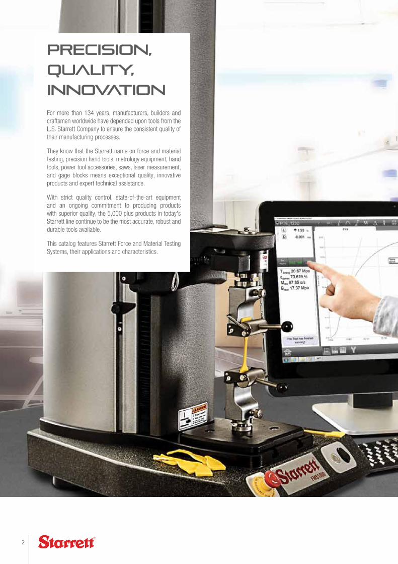
For more than 134 years, manufacturers, builders and craftsmen worldwide have depended upon tools from the L.S. Starrett Company to ensure the consistent quality of their manufacturing processes.
They know that the Starrett name on force and material testing, precision hand tools, metrology equipment, hand tools, power tool accessories, saws, laser measurement, and gage blocks means exceptional quality, innovative products and expert technical assistance.
With strict quality control, state-of-the-art equipment and an ongoing commitment to producing products with superior quality, the 5,000 plus products in today's Starrett line continue to be the most accurate, robust and durable tools available.
This catalog features Starrett Force and Material Testing Systems, their applications and characteristics.
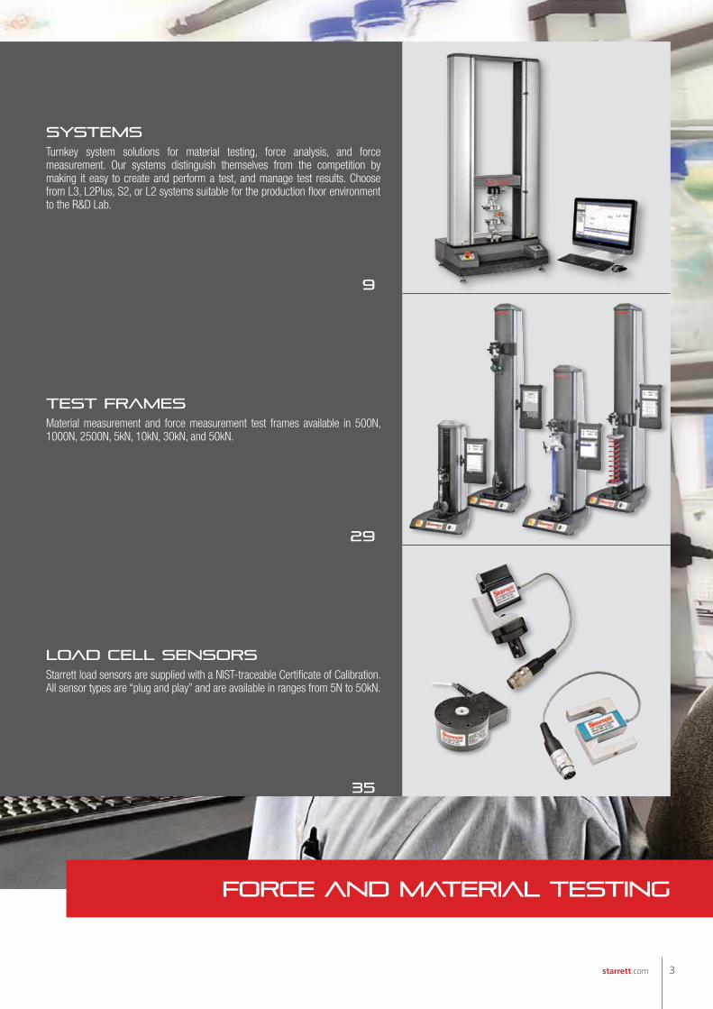
SystemsTurnkey system solutions for material testing, force analysis, and force measurement. Our systems distinguish themselves from the competition by making it easy to create and perform a test, and manage test results. Choose from L3, L2Plus, S2, or L2 systems suitable for the production floor environment to the R&D Lab.
9
Test FramesMaterial measurement and force measurement test frames available in 500N, 1000N, 2500N, 5kN, 10kN, 30kN, and 50kN.
29
Load Cell SensorsStarrett load sensors are supplied with a NIST-traceable Certificate of Calibration. All sensor types are “plug and play” and are available in ranges from 5N to 50kN.
35
3starrett.com
FORCE AND MATERIAL TESTING
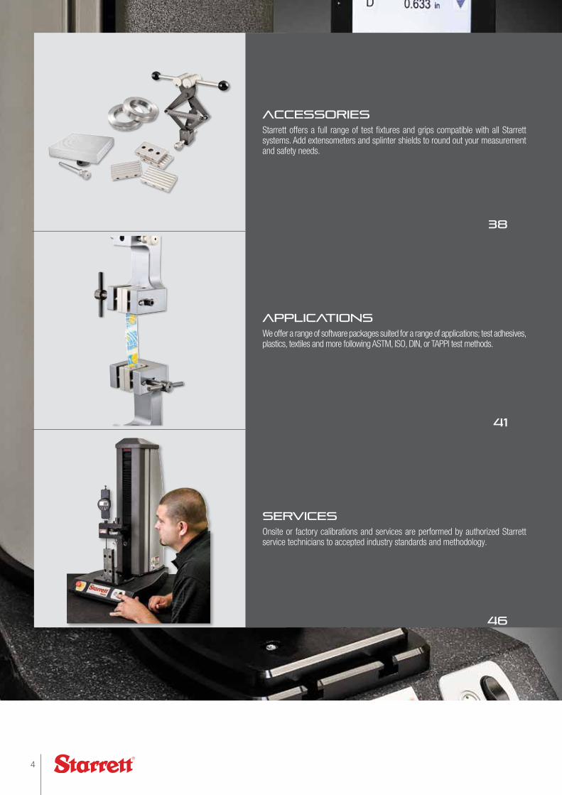
AccessoriesStarrett offers a full range of test fixtures and grips compatible with all Starrett systems. Add extensometers and splinter shields to round out your measurement and safety needs.
38
ApplicationsWe offer a range of software packages suited for a range of applications; test adhesives, plastics, textiles and more following ASTM, ISO, DIN, or TAPPI test methods.
41
ServicesOnsite or factory calibrations and services are performed by authorized Starrett service technicians to accepted industry standards and methodology.
46
4

AccessoriesStarrett offers a full range of test fixtures and grips compatible with all Starrett systems. Add extensometers and splinter shields to round out your measurement and safety needs.
38
ApplicationsWe offer a range of software packages suited for a range of applications; test adhesives, plastics, textiles and more following ASTM, ISO, DIN, or TAPPI test methods.
41
ServicesOnsite or factory calibrations and services are performed by authorized Starrett service technicians to accepted industry standards and methodology.
46
Vision SystemsStarrett vision systems combine high-resolution images with robust, precision mechanical platforms. We offer a full range of systems from video microscopes to large 50 x 36" (1270 x 915mm) platform systems and our Mx digital metrology software.
Granite Surface PlatesStarrett granite surface plates are available in three levels of accuracy: Grade AA (Laboratory), Grade A (Inspection) and Grade B (Tool room). Our Crystal Pink granite has the highest percentage of quartz of any granite so it has the best balance of physical properties, maximum resistance to wear and for deflection under load.
IndicatorsStarrett manufactures an array of gages and indicators for exacting measuring applications. We offer test indicators, back plunger indicators, dial indicators, and accessories. We can supply analog and digital indicators, plus special application indicators for your application requirements.
Optical ComparatorsStarrett optical comparators are ideal for a wide range of dimensional inspection applications. Starrett offers optical systems from 16-30" (400-750 mm) diameters, horizontal and vertical models.
Height GagesFor simple or complex height measurements, Starrett supplies a range of electronic height gages and accessories, including the DIGI-CHEK system- the world's fastest and most precise height masters.
Laser MeasurementsStarrett is a leader in non-contact laser measurement systems such as our Profile 360 system. The system continuously monitors the size and shape of complex profiles to ensure quality and consistency in width, thickness, gap, radius, angle and more.
Bore GagesOur AccuBore electronic bore indicators is a high-quality, trigger-activated, three-point contact bore gaging system. Starrett can supply a wide range of bore gage systems that ensure a more true alignment.
Webber Gage BlocksStarrett precision gage blocks are trusted for their accuracy, surface finish, wear resistance and dimensional stability. Our croblox® gage block is the world's premier gage block with industry-leading accuracy and stability.
Precision ToolsStarrett has a comprehensive range of micrometers and calipers that meet or exceed accuracy and performance specifications of national and international standards.
Product Lines
5starrett.com
Prod
uct L
ines

6
TorontoCanada
JedburghScotland
ClevelandUSA
Waite ParkUSA
AtholUSA
SchmittenGermany
SaltilloMexico
Itu Brazil
Laguna HillsUSA
Mount AiryUSA
ColumbusUSA
Starrett Distribution Centers and OfficesFactories and Distribution Centers
1
8
7
5
6
4
3
2
Factorie
s
Factories Around the World
1-Athol, Massachusetts, USA 2-Laguna Hills, Califórnia, USA 3-Waite Park, Minnesota, USA 4-Cleveland, Ohio, USA

7starrett.com
SuzhouChina
SidneyAustralia
AucklandNew Zeland
Singapore
TokyoJapan
ShanghaiChina
9
MumbaiIndia
Factorie
s
5-Mount Airy, North Carolina, USA 6-Columbus, Georgia, USA 7-Itu, São Paulo, Brazil 8-Jedburgh, Scotland 9-Suzhou, China

Large, 8-inch (203mm) platform
Emergency stop switch
Manual jog switch
Test Start/Stop switch and status indicator.
Granite base for exceptional stiffness
Extruded aluminum column ensures excellent rigidity
PC with Windows® OS with high-resolution, color touchscreen display. Adjust position for comfort.
Interchangeable load sensors comply with IEEE 1451.4. Accurate to ±0.05% Full Scale.
Integral blinds protect mechanical motion controls from debris.
Adjustable over-travel limits prevent accidental overloading
User-adjustable corrections for linear error and deflection compensation
Export using USB and interface to wireless devices using Bluetooth®.
Equipped with optionally available splinter shield with interlocking
overview
starrett innovation. Precision.
ACCURACY. EASY TO USE.
When you need an easy-to-use measurement system for accurately and precisely determining spring rates, spring constants, spring lengths and other spring characteristics, you can rely on Starrett- a trusted leader in measurement and innovation.
Our simple, fill-in-the-blank test setups let you test and validate your springs in as few as three steps allowing your testing to be performed in seconds. And your test results can be viewed, graphed and reported, including exporting up to 1000 data points per second to a spreadsheet or to your networked quality control software. It's the accuracy, repeatability and simplicity you expect from L. S. Starrett.
8
ov
erv
iew

SYSTEMS
L3 systems
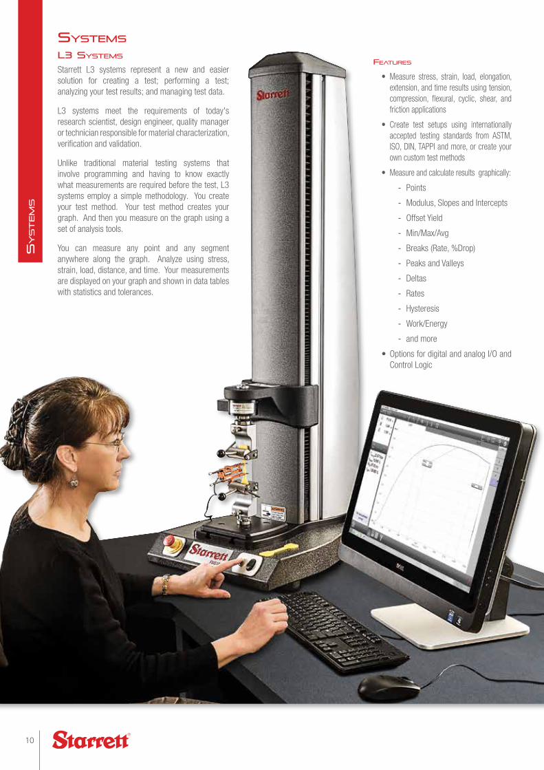
Starrett L3 systems represent a new and easier solution for creating a test; performing a test; analyzing your test results; and managing test data.
L3 systems meet the requirements of today's research scientist, design engineer, quality manager or technician responsible for material characterization, verification and validation.
Unlike traditional material testing systems that involve programming and having to know exactly what measurements are required before the test, L3 systems employ a simple methodology. You create your test method. Your test method creates your graph. And then you measure on the graph using a set of analysis tools.
You can measure any point and any segment anywhere along the graph. Analyze using stress, strain, load, distance, and time. Your measurements are displayed on your graph and shown in data tables with statistics and tolerances.
systems
Features
• Measure stress, strain, load, elongation, extension, and time results using tension, compression, flexural, cyclic, shear, and friction applications
• Create test setups using internationally accepted testing standards from ASTM, ISO, DIN, TAPPI and more, or create your own custom test methods
• Measure and calculate results graphically:
- Points
- Modulus, Slopes and Intercepts
- Offset Yield
- Min/Max/Avg
- Breaks (Rate, %Drop)
- Peaks and Valleys
- Deltas
- Rates
- Hysteresis
- Work/Energy
- and more
• Options for digital and analog I/O and Control Logic
10
SyStem
S
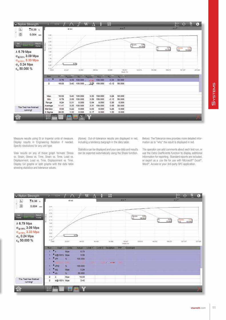
Measure results using SI or Imperial units of measure. Display results in Engineering Notation if needed. Specify resolutions for any unit type.
View results on any of these graph formats: Stress vs. Strain, Stress vs. Time, Strain vs. Time, Load vs. Displacement, Load vs. Time, Displacement vs. Time. Display full graphs or split graphs with the data table showing statistics and tolerance values.
(Above) Out-of-tolerance results are displayed in red, including a tendency bargraph in the data table.
Statistics can be displayed and your raw data and results can be exported automatically using the Share function.
Below) The Tolerance view provides more detailed infor-mation as to "why" the result is displayed in red.
The operator can add comments about each test run, or use the Extra Coefficients function to display additional information for reporting. Standard reports are included, or export as a .csv file for use with Microsoft® Excel®, Word®, Access or your 3rd-party SPC application.
11starrett.com
SyStem
S

Construct simple and complex multi-step test setups. Create your test method to an accepted standard or to your specific testing needs.
Create your test method and then email to other locations so that your testing is always performed in the exact same manner with the same measurements and results.
Shown are the various test setup step types, including specialized steps available using the optional Automation Builder.
L3 systems
Tensile and Compression steps are used to perform "go to moves". Go to a Limit or Break at a velocity or load rate. You can choose exceptions for any move and decide whether to collect data during the move.
Shown is an operator prompt based on a conditional branching state. If the measured result is "out-of-tolerance", a message is displayed alerting the operator. If the result is within the tolerance range, no message is displayed.
Hold steps are used for creep and relaxation testing. You can hold at a limit for a specified duration up to 24 hours, if necessary.
Cycle based on any of your steps in your test method. You may cycle up to 1000 times or for a duration of up to 24 hours at a sampling rate of 1Hz. Each test may have a maximum of 100,000 data points.
The Sample Definition step lets you name your material, specify the shape and its dimensions. You can enter dimensions digitally using a Starrett micrometer, or caliper.
Shown is the setup dialog for the optional I/O step. It allows you to control and activate external devices such as annunciators through the test frame's digital or analog I/O channels.
systems
12
SyStem
S
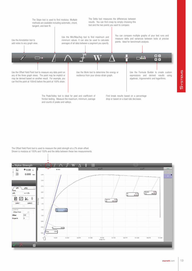
Use the Annotation tool to add notes to any graph view.
Use the Offset Yield Point tool to measure any data point on any of the three graph views. The point may be implicit or may be derived based on another result. For example, you can find the point at 100mS before the point at 100% strain.
Use the Formula Builder to create custom expressions and derived results using algebraic, trigonometric and logarithms.
Find break results based on a percentage drop or based on a load rate decrease.
Use the Work tool to determine the energy or resilience from your stress-strain graph.
The Peak/Valley tool is ideal for peel and coefficient of friction testing. Measure the maximum, minimum, average and counts of peaks and valleys.
The Slope tool is used to find modulus. Multiple methods are available including automatic, chord, tangent, and best fit.
Use the Min/Max/Avg tool to find maximum and minimum values. It can also be used to calculate averages of all data between a segment you specify.
You can compare multiple graphs of your test runs and measure delta and variances between tests at precise points. Ideal for benchmark analysis.
The Delta tool measures the differences between results. You can find creep by simply choosing this tool and the two points you want to compare.
The Offset Yield Point tool is used to measure the yield strength at a 2% strain offset.Shown is modulus at 100% and 150% and the delta between these two measurements.
13starrett.com
SyStem
S
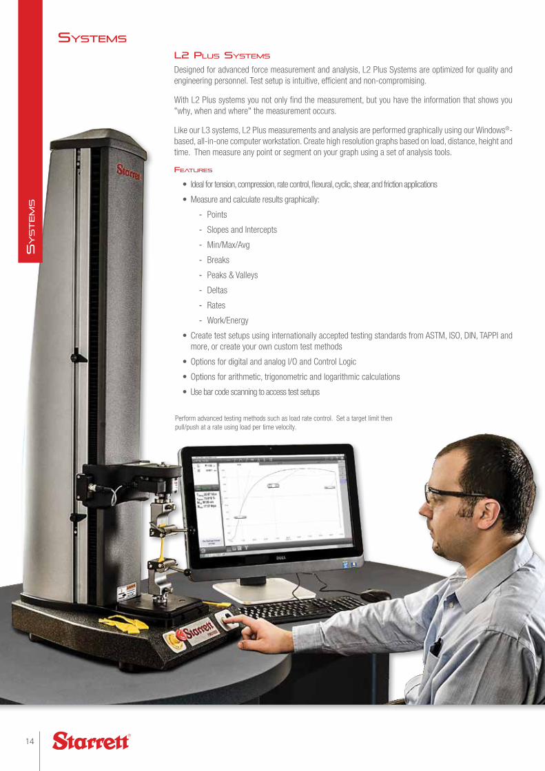
L2 PLus systems
Designed for advanced force measurement and analysis, L2 Plus Systems are optimized for quality and engineering personnel. Test setup is intuitive, efficient and non-compromising.
With L2 Plus systems you not only find the measurement, but you have the information that shows you "why, when and where" the measurement occurs.
Like our L3 systems, L2 Plus measurements and analysis are performed graphically using our Windows®-based, all-in-one computer workstation. Create high resolution graphs based on load, distance, height and time. Then measure any point or segment on your graph using a set of analysis tools.
Features
• Ideal for tension, compression, rate control, flexural, cyclic, shear, and friction applications
• Measure and calculate results graphically:
- Points
- Slopes and Intercepts
- Min/Max/Avg
- Breaks
- Peaks & Valleys
- Deltas
- Rates
- Work/Energy
• Create test setups using internationally accepted testing standards from ASTM, ISO, DIN, TAPPI and more, or create your own custom test methods
• Options for digital and analog I/O and Control Logic
• Options for arithmetic, trigonometric and logarithmic calculations
• Use bar code scanning to access test setups
systems
Perform advanced testing methods such as load rate control. Set a target limit then pull/push at a rate using load per time velocity.
14
SyStem
S

Specific algorithms for peak & valley measurements are supported: find peak/valley, find maximum/minimum peak/valley, find averages for peaks/valleys.
Your results can be displayed in markers on your graph, in data tables, or in combinations. Graph types are: Load vs. Distance, Load vs. Time, and Distance vs. Time. Markers can display the load, distance and time to a specific point on the graph.
(Above) Use the Peak/Valley tool to locate the peaks for the entire test duration or for a defined segment within the test. per ASTM F88 Qualify your peaks and valleys using the sensitivity adjustment. Measure average, counts, maximum, minimum and more.
(Below) The load average is calculated for qualified peak values using a load sensitivity of 25%. Adjust for sensitivity using the data definition menu or by using the sensitivity adjustment bar on the y-axis. In this example, the load average is specified at a segment starting at the maximum load point (Lmax).
15starrett.com
SyStem
S
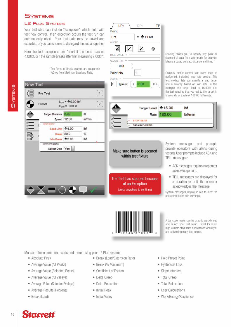
Complex motion-control test steps may be performed, including load rate control. This test method lets you specify a load target and a velocity based on load rate. In this example, the target load is 15.00lbf and the test requires that you get to the target in 5 seconds, or a rate of 180.00 lbf/minute.
Measure these common results and more using your L2 Plus system:
Scoping allows you to specify any point or segment of data from your graph for analysis. Measure based on load, distance and time.
Two forms of Break analysis are supported: %Drop from Maximum Load and Rate.
System messages and prompts provide operators with alerts during testing. User prompts include ASK and TELL messages:
• ASK messages require an operator acknowledgement.
• TELL messages are displayed for a duration or until the operator acknowledges the message.
System messages display in red to alert the operator to alerts and warnings.
A bar code reader can be used to quickly load and launch your test setup. Ideal for busy, high-volume production applications where you are performing many test setups.
L2 PLus systems
Your test step can include "exceptions" which help with test flow control. If an exception occurs the test run can automatically abort. Your test data may be saved and exported, or you can choose to disregard the test altogether.
Here the test exceptions are "abort if the Load reaches 4.00lbf, or if the sample breaks after first measuring 2.00lbf".
• Absolute Peak
• Average Value (All Peaks)
• Average Value (Selected Peaks)
• Average Value (All Valleys)
• Average Value (Selected Valleys)
• Average Results (Regions)
• Break (Load)
• Break (Load/Extension Rate)
• Break (% Maximum)
• Coefficient of Friction
• Delta Creep
• Delta Relaxation
• Initial Peak
• Initial Valley
• Hold Preset Point
• Hysteresis Loss
• Slope Intersect
• Total Creep
• Total Relaxation
• User Calculations
• Work/Energy/Resilience
Make sure button is secured within test fixture
The Test has stopped because of an Exception
(press anywhere to continue)
systems
16
SyStem
S
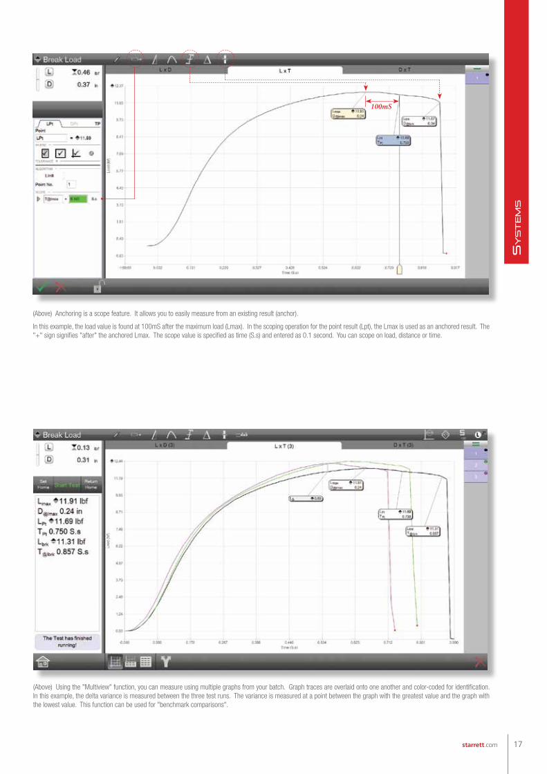
100mS
(Above) Anchoring is a scope feature. It allows you to easily measure from an existing result (anchor).
In this example, the load value is found at 100mS after the maximum load (Lmax). In the scoping operation for the point result (Lpt), the Lmax is used as an anchored result. The "+" sign signifies "after" the anchored Lmax. The scope value is specified as time (S.s) and entered as 0.1 second. You can scope on load, distance or time.
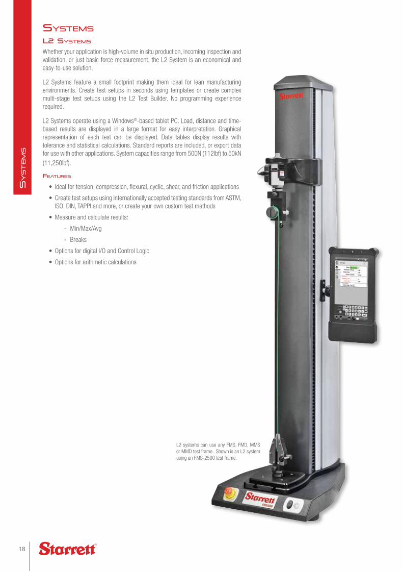
(Above) Using the "Multiview" function, you can measure using multiple graphs from your batch. Graph traces are overlaid onto one another and color-coded for identification. In this example, the delta variance is measured between the three test runs. The variance is measured at a point between the graph with the greatest value and the graph with the lowest value. This function can be used for "benchmark comparisons".
17starrett.com
SyStem
S
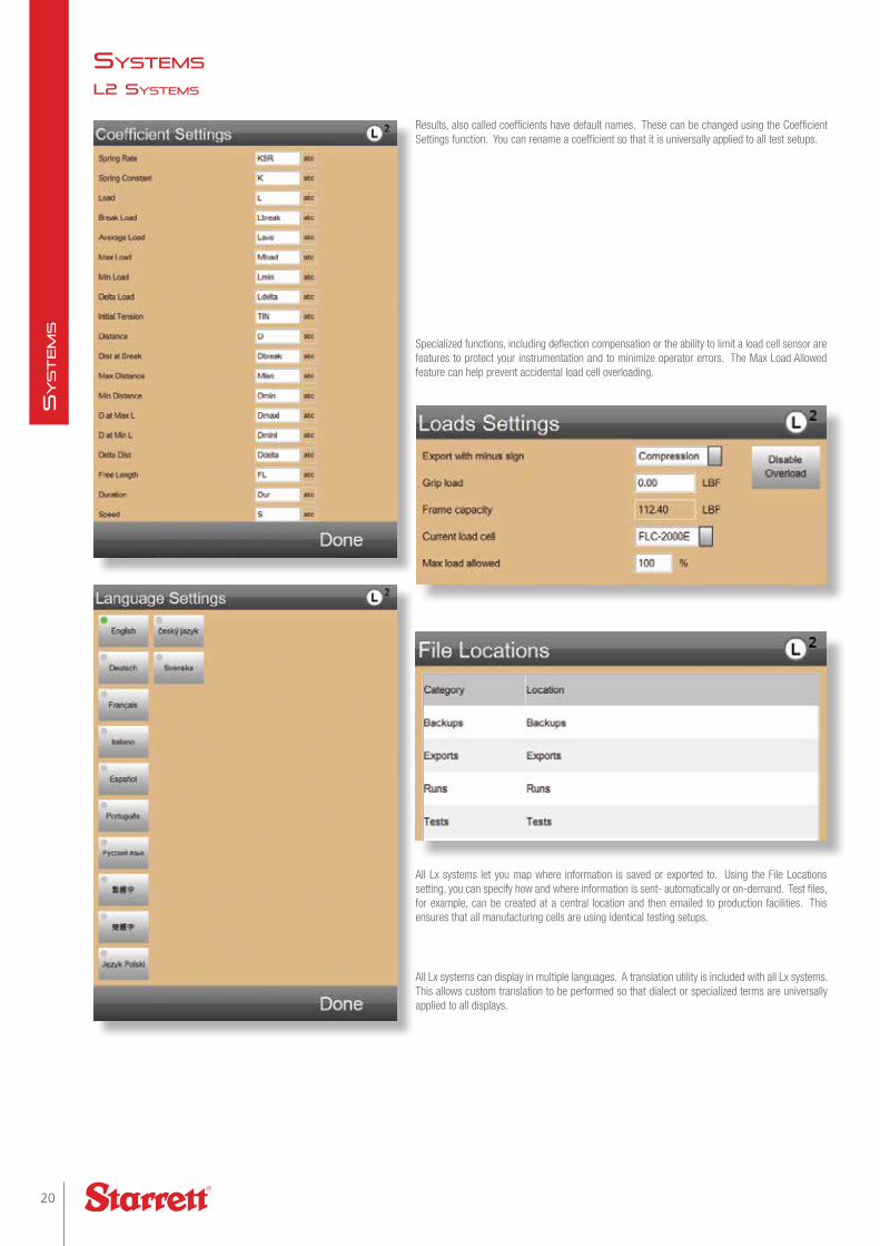
L2 systems
Whether your application is high-volume in situ production, incoming inspection and validation, or just basic force measurement, the L2 System is an economical and easy-to-use solution.
L2 Systems feature a small footprint making them ideal for lean manufacturing environments. Create test setups in seconds using templates or create complex multi-stage test setups using the L2 Test Builder. No programming experience required.
L2 Systems operate using a Windows®-based tablet PC. Load, distance and time-based results are displayed in a large format for easy interpretation. Graphical representation of each test can be displayed. Data tables display results with tolerance and statistical calculations. Standard reports are included, or export data for use with other applications. System capacities range from 500N (112lbf) to 50kN (11,250lbf).
Features
• Ideal for tension, compression, flexural, cyclic, shear, and friction applications
• Create test setups using internationally accepted testing standards from ASTM, ISO, DIN, TAPPI and more, or create your own custom test methods
• Measure and calculate results:
- Min/Max/Avg
- Breaks
• Options for digital I/O and Control Logic
• Options for arithmetic calculations
L2 systems can use any FMS, FMD, MMS or MMD test frame. Shown is an L2 system using an FMS-2500 test frame.
systems
18
SyStem
S

The Starrett L2 system features a tablet computer featuring a 10-inch (254mm) color, touchscreen display. The system is WiFi®, Bluetooth® and USB compatible.
Perform common test methods such as determining maximum load, maximum deflection, average loads or how product reacts when a constant load is applied for a specified period of time.
L2 systems can determine break strengths and the sample's characteristics at load and extension limit values and provide you with immediate pass/fail indication.
The L2 system includes test templates- pre-configured test setups for load, distance and break limit testing. These can be used to setup a test in seconds. Simply fill in the blanks and your setup is complete.Use the Convert to Test Builder function and your test template is converted to a full Test Builder setup.
Use the Test Builder application supplied standard with L2 systems to construct simple and complex test setups. This example shows a contact closure test that also uses the optional Automation Builder and digital I/O. The Test Builder methodology is same across all Lx systems.
19starrett.com
SyStem
S
All Lx systems let you map where information is saved or exported to. Using the File Locations setting, you can specify how and where information is sent- automatically or on-demand. Test files, for example, can be created at a central location and then emailed to production facilities. This ensures that all manufacturing cells are using identical testing setups.
All Lx systems can display in multiple languages. A translation utility is included with all Lx systems. This allows custom translation to be performed so that dialect or specialized terms are universally applied to all displays.
Results, also called coefficients have default names. These can be changed using the Coefficient Settings function. You can rename a coefficient so that it is universally applied to all test setups.
Specialized functions, including deflection compensation or the ability to limit a load cell sensor are features to protect your instrumentation and to minimize operator errors. The Max Load Allowed feature can help prevent accidental load cell overloading.
L2 systems
systems
20
SyStem
S

The Statistics view displays the results and their associated statistical values. The header displays the total, passed and failed test runs. Failed runs display in red.
The Results view can be configured to display the most critical result in large text.
The Tolerance view shows the results and the tolerance limits. Test runs that are "out-of-tolerance" display in red with a tendency bar graph for analysis.
L2 systems display a graph profile. Unlike the L3 and L2 Plus systems, no measurement can be performed from the graph. Selecting the Graph symbol changes the graph axes. Graphs may be overlaid.
21starrett.com
SyStem
S
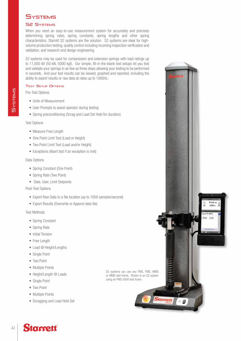
s2 systems
When you need an easy-to-use measurement system for accurately and precisely determining spring rates, spring constants, spring lengths and other spring characteristics, Starrett S2 systems are the solution. S2 systems are ideal for high-volume production testing, quality control including incoming inspection verification and validation, and research and design engineering.
S2 systems may be used for compression and extension springs with load ratings up to 11,000 lbf (50 kN, 5000 kgf). Our simple, fill-in-the-blank test setups let you test and validate your springs in as few as three steps allowing your testing to be performed in seconds. And your test results can be viewed, graphed and reported, including the ability to export results or raw data at rates up to 1000Hz.
test setuP oPtions
Pre-Test Options
• Units of Measurement
• User Prompts to assist operator during testing
• Spring preconditioning (Scrag and Load Set Hold for duration)
Test Options
• Measure Free Length
• One Point Limit Test (Load or Height)
• Two Point Limit Test (Load and/or Height)
• Exceptions (Abort test if an exception is met)
Data Options
• Spring Constant (One Point)
• Spring Rate (Two Point)
• Date, User, Limit Setpoints
Post-Test Options
• Export Raw Data to a file location (up to 1000 samples/second)
• Export Results (Overwrite or Append data file)
Test Methods
• Spring Constant
• Spring Rate
• Initial Tension
• Free Length
• Load @ Height/Lengths
• Single Point
• Two Point
• Multiple Points
• Height/Length @ Loads
• Single Point
• Two Point
• Multiple Points
• Scragging and Load Hold Set
S2 systems can use any FMS, FMD, MMS or MMD test frame. Shown is an S2 system using an FMS-5000 test frame.
systems
22
SyStem
S
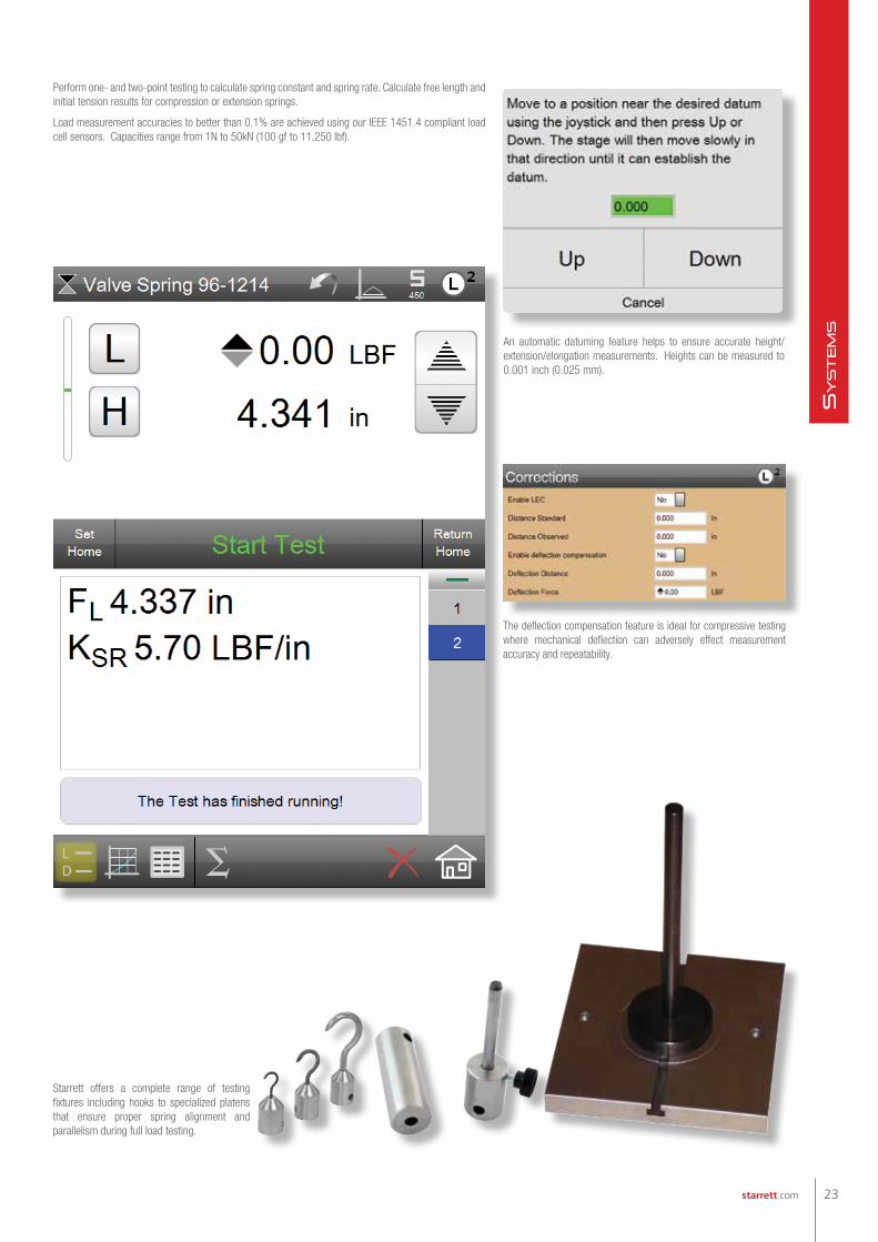
Starrett offers a complete range of testing fixtures including hooks to specialized platens that ensure proper spring alignment and parallelism during full load testing.
The deflection compensation feature is ideal for compressive testing where mechanical deflection can adversely effect measurement accuracy and repeatability.
An automatic datuming feature helps to ensure accurate height/extension/elongation measurements. Heights can be measured to 0.001 inch (0.025 mm).
Perform one- and two-point testing to calculate spring constant and spring rate. Calculate free length and initial tension results for compression or extension springs.
Load measurement accuracies to better than 0.1% are achieved using our IEEE 1451.4 compliant load cell sensors. Capacities range from 1N to 50kN (100 gf to 11,250 lbf).
23starrett.com
SyStem
S

Create compression and extension tests using the test templates supplied standard with your S2 system. Or, use the optional Test Builder application to create sophisticated, multi-point test setups for more advanced spring measurement.
The optional S2 Automation Builder software works with the S2 Test Builder application so you can use conditional branching and digital I/O to interface with ancillary equipment such as annunciators, conveyors and turret loading devices.
During your test, status messages display providing the operator with immediate feedback of the active step and the step's performance characteristics and current measurement. An LED on the Start/Stop push button on your test frame also indicates and active test condition.
Preconditioning options include scragging and load set.
(Above) You can scrag your spring based on a number of cycles or based on a time duration.
(Below) Your spring may be set solid as a preconditioning prior to your actual test procedure. For example, compress to 12 lbf and hold for 1 minute.
The Pre Test step lets you specify test attributes before you actually begin your testing. Set units of measure, pre-conditioning, user prompts and datum criterion.
s2 systems
systems
24
SyStem
S
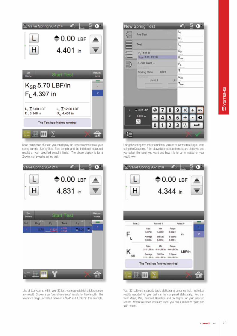
Your S2 software supports basic statistical process control. Individual results reported for your test can be compared statistically. You can view Mean, Min, Standard Deviation and Six Sigma for your selected results. When tolerance limits are used, you can summarize "pass and fail" results.
Using the spring test setup templates, you can select the results you want using the Data step. A list of available standard results are displayed and you select the result you want and how it is to be formatted on your result view.
Upon completion of a test, you can display the key characteristics of your spring sample: Spring Rate, Free Length, and the individual measured results at your specified setpoint limits. The above display is for a 2-point compressive spring test.
Like all Lx systems, within your S2 test, you may establish a tolerance on any result. Shown is an "out-of-tolerance" results for free length. The tolerance range is created between 4.394" and 4.398" in this example.
25starrett.com
SyStem
S

Starrett Lx systems can be interfaced with ancillary instrumentation for factory automation applications or where more advanced and complex measurements are necessary.
The optional Automation Builder software packages can be used for interfacing with instrumentation and equipment through digital and analog I/O signals.
The Automation Builder can also be used to incorporate conditional logic within your test setup. Conditional logic can be used to establish If/Else relationships, including the ability to automatically adjust test setup functionality based on events that occur during a test run.
Digital I/O is available on all MMx and FMx test frames. Analog I/O is only available using the MMS or MMD test frames.
Digital I/O can be used for contact closure testing. You can measure and determine the precise load that caused the "make" or "break" in an electronic component or switch. You may also use conditional logic combined with the digital outputs to light an annunciator based on a tolerance result.
(Above) A conditional branching occurs when the Lmax result is out-of-tolerance. This will cause a message to display to the operator and it will cause a signal annunciator to light red for a failed test sample.
automation
26
SyStem
S

This example shows a full graph view of an adhesive test. Three peaks are identified based on the sensitivity of 14.1 after the Lmax (maximum peak).
The qualified peaks are highlighted in blue and identified as Lmax1, Lmax2 and Lmax3.
Automation Builder Software OptionMeasurement Capabilities L3 L2 Plus L2 S2Use Digital I/O m m m m
Use Analog I/O (requires MMx test frames) m m
Use Command and Conditional Logic m m m m
Formula BuilderCreate Basic Expressions using Add, Subtract, Multiple and Divide Std1 m m m
Create Mathematical Expressions using Algebraic, Trigonometric and Logarithmic functions Std1 m
Notes: (1) The Formula Builder function is supplied standard on L3 systems only. The Formula Builder is included in the optional Automation Builder software for L2 Plus, L2 and S2 systems.Advanced mathematical expressions using algebraic, trigonometric and logarithmic functions are available on L3 and L2 Plus systems only.
The Formula Builder allows you to construct complex, derived results using arithmetic, trigonometric and logarithmic expressions. The Formula Builder is standard in L3 systems and optional for L2 Plus, L2 and S2 systems. The Formula Builder for L2 and S2 systems supports basic arithmetic functions only- add, subtract, multiply and divide.
Using the Formula Builder, an expression was created that is an average of the three Lmax values only. The Lavg in this example application does not average all data points, but only the Lmax values.
The formula you create is evaluated real-time. Syntax errors are noted by displaying a red line around the formula input box. If the formula is correct, the line is green.
The functions and features available using the optional Automation Builder software are shown in the table.
The Formula Builder is supplied standard on L3 systems only.
Advanced mathematical expressions are not available with the Formula Builder in the L2 and S2 system's optional Automation Builder application.
27starrett.com
SyStem
S

Follow us!
(978) 249-3551 • starrett.com
Goes the distance.
Three major product lines to
meet our customer's needs with
performance and quality.
Precision makes the Difference
Test Frames
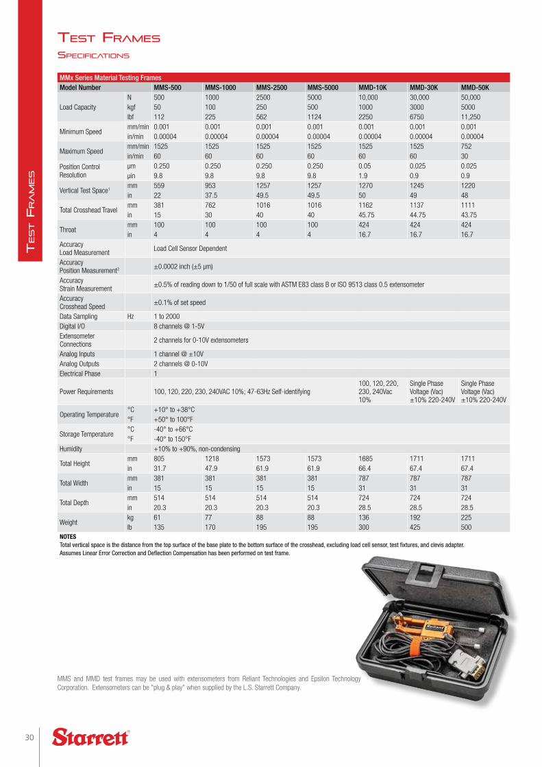
MMx Series Material Testing FramesModel Number MMS-500 MMS-1000 MMS-2500 MMS-5000 MMD-10K MMD-30K MMD-50K
Load CapacityN 500 1000 2500 5000 10,000 30,000 50,000kgf 50 100 250 500 1000 3000 5000lbf 112 225 562 1124 2250 6750 11,250
Minimum Speedmm/min 0.001 0.001 0.001 0.001 0.001 0.001 0.001in/min 0.00004 0.00004 0.00004 0.00004 0.00004 0.00004 0.00004
Maximum Speedmm/min 1525 1525 1525 1525 1525 1525 752in/min 60 60 60 60 60 60 30
Position Control Resolution
µm 0.250 0.250 0.250 0.250 0.05 0.025 0.025µin 9.8 9.8 9.8 9.8 1.9 0.9 0.9
Vertical Test Space1mm 559 953 1257 1257 1270 1245 1220in 22 37.5 49.5 49.5 50 49 48
Total Crosshead Travelmm 381 762 1016 1016 1162 1137 1111in 15 30 40 40 45.75 44.75 43.75
Throatmm 100 100 100 100 424 424 424in 4 4 4 4 16.7 16.7 16.7
Accuracy Load Measurement Load Cell Sensor Dependent
Accuracy Position Measurement2 ±0.0002 inch (±5 μm)
Accuracy Strain Measurement ±0.5% of reading down to 1/50 of full scale with ASTM E83 class B or ISO 9513 class 0.5 extensometer
Accuracy Crosshead Speed ±0.1% of set speed
Data Sampling Hz 1 to 2000Digital I/O 8 channels @ 1-5VExtensometer Connections 2 channels for 0-10V extensometers
Analog Inputs 1 channel @ ±10VAnalog Outputs 2 channels @ 0-10VElectrical Phase 1
Power Requirements 100, 120, 220, 230, 240VAC 10%; 47-63Hz Self-identifying100, 120, 220, 230, 240Vac 10%
Single Phase Voltage (Vac) ±10% 220-240V
Single Phase Voltage (Vac) ±10% 220-240V
Operating Temperature°C +10° to +38°C°F +50° to 100°F
Storage Temperature°C -40° to +66°C°F -40° to 150°F
Humidity +10% to +90%, non-condensing
Total Heightmm 805 1218 1573 1573 1685 1711 1711in 31.7 47.9 61.9 61.9 66.4 67.4 67.4
Total Widthmm 381 381 381 381 787 787 787in 15 15 15 15 31 31 31
Total Depthmm 514 514 514 514 724 724 724in 20.3 20.3 20.3 20.3 28.5 28.5 28.5
Weightkg 61 77 88 88 136 192 225lb 135 170 195 195 300 425 500
NOTESTotal vertical space is the distance from the top surface of the base plate to the bottom surface of the crosshead, excluding load cell sensor, test fixtures, and clevis adapter.Assumes Linear Error Correction and Deflection Compensation has been performed on test frame.
MMS and MMD test frames may be used with extensometers from Reliant Technologies and Epsilon Technology Corporation. Extensometers can be "plug & play" when supplied by the L.S. Starrett Company.
sPeciFications
test Frames
30
TesT F
ra
mes

FMx Series Force Measurement FramesModel Number FMS-500 FMS-1000 FMS-2500 FMS-5000 FMD-10K FMD-30K FMD-50K
Load CapacityN 500 1000 2500 5000 10,000 30,000 50,000kgf 50 100 250 500 1000 3000 5000lbf 112 225 562 1124 2250 6750 11,250
Minimum Speedmm/min 0.05 0.05 0.05 0.05 0.05 0.05 0.05in/min 0.002 0.002 0.002 0.002 0.002 0.002 0.002
Maximum Speedmm/min 1525 1525 1525 1525 1525 1525 752in/min 60 60 60 60 60 60 30
Position Control Resolution
µm 0.250 0.250 0.250 0.250 0.05 0.025 0.025µin 9.8 9.8 9.8 9.8 1.9 0.9 0.9
Vertical Test Space1mm 559 953 1257 1257 1270 1245 1220in 22 37.5 49.5 49.5 50 49 48
Total Crosshead Travelmm 381 762 1016 1016 1162 1137 1111in 15 30 40 40 45.75 44.75 43.75
Throatmm 100 100 100 100 424 424 424in 4 4 4 4 16.7 16.7 16.7
Accuracy Load Measurement Load Cell Sensor Dependent
Accuracy Position Measurement2 ±0.001inch (±20 µm)
Accuracy Crosshead Speed ±0.1% of set speed
Data Sampling Hz 5 to 1000Digital I/O 8 channels @ 1-5VElectrical Phase 1
Power Requirements 100, 120, 220, 230, 240VAC 10%; 47-63Hz Self-identifying100, 120, 220, 230, 240Vac 10%
Single Phase Voltage (Vac) ±10% 220-240V
Single Phase Voltage (Vac) ±10% 220-240V
Operating Temperature
°C +10° to +38°C°F +50° to 100°F
Storage Temperature
°C -40° to +66°C°F -40° to 150°F
Humidity +10% to +90%, non-condensing
Total Heightmm 805 1218 1573 1573 1685 1711 1711in 31.7 47.9 61.9 61.9 66.4 67.4 67.4
Total Widthmm 381 381 381 381 787 787 787in 15 15 15 15 31 31 31
Total Depthmm 514 514 514 514 724 724 724in 20.3 20.3 20.3 20.3 28.5 28.5 28.5
Weightkg 61 77 88 88 136 192 225lb 135 170 195 195 300 425 500
NOTESTotal vertical space is the distance from the top surface of the base plate to the bottom surface of the crosshead, excluding load cell sensor, test fixtures, and clevis adapter. Assumes Linear Error Correction and Deflection Compensation has been performed on test frame.
Shown: L2 system with FMS500 test frame with tablet.
31starrett.com
TesT F
ra
mes
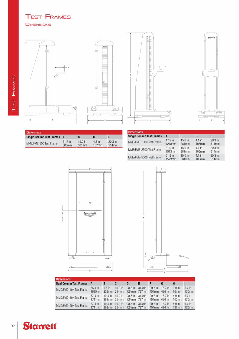
DimensionsDual Column Test Frames A B C D E F G H I
MMD/FMD-10K Test Frame 66.4 in 1685mm
9.4 in 238mm
10.0 in 254mm
28.5 in 724mm
31.0 in 787mm
29.7 in 754mm
16.7 in 424mm
3.0 in 76mm
6.7 in 170mm
MMD/FMD-30K Test Frame 67.4 in 1711mm
10.4 in 263mm
10.0 in 254mm
28.5 in 724mm
31.0 in 787mm
29.7 in 754mm
16.7 in 424mm
4.0 in 102mm
6.7 in 170mm
MMD/FMD-50K Test Frame 67.4 in 1711mm
10.4 in 263mm
10.0 in 254mm
28.5 in 724mm
31.0 in 787mm
29.7 in 754mm
16.7 in 424mm
5.0 in 127mm
6.7 in 170mm
DimensionsSingle Column Test Frames A B C D
MMS/FMS-500 Test Frame 31.7 in 805mm
15.0 in 381mm
4.2 in 107mm
20.3 in 514mm
DimensionsSingle Column Test Frames A B C D
MMS/FMS-1000 Test Frame 47.9 in 1218mm
15.0 in 381mm
4.1 in 105mm
20.3 in 514mm
MMS/FMS-2500 Test Frame 61.9 in 1573mm
15.0 in 381mm
4.1 in 105mm
20.3 in 514mm
MMS/FMS-5000 Test Frame 61.9 in 1573mm
15.0 in 381mm
4.1 in 105mm
20.3 in 514mm
dimensions
F I
E
G
A
H
B
DC
test Frames
32
TesT F
ra
mes
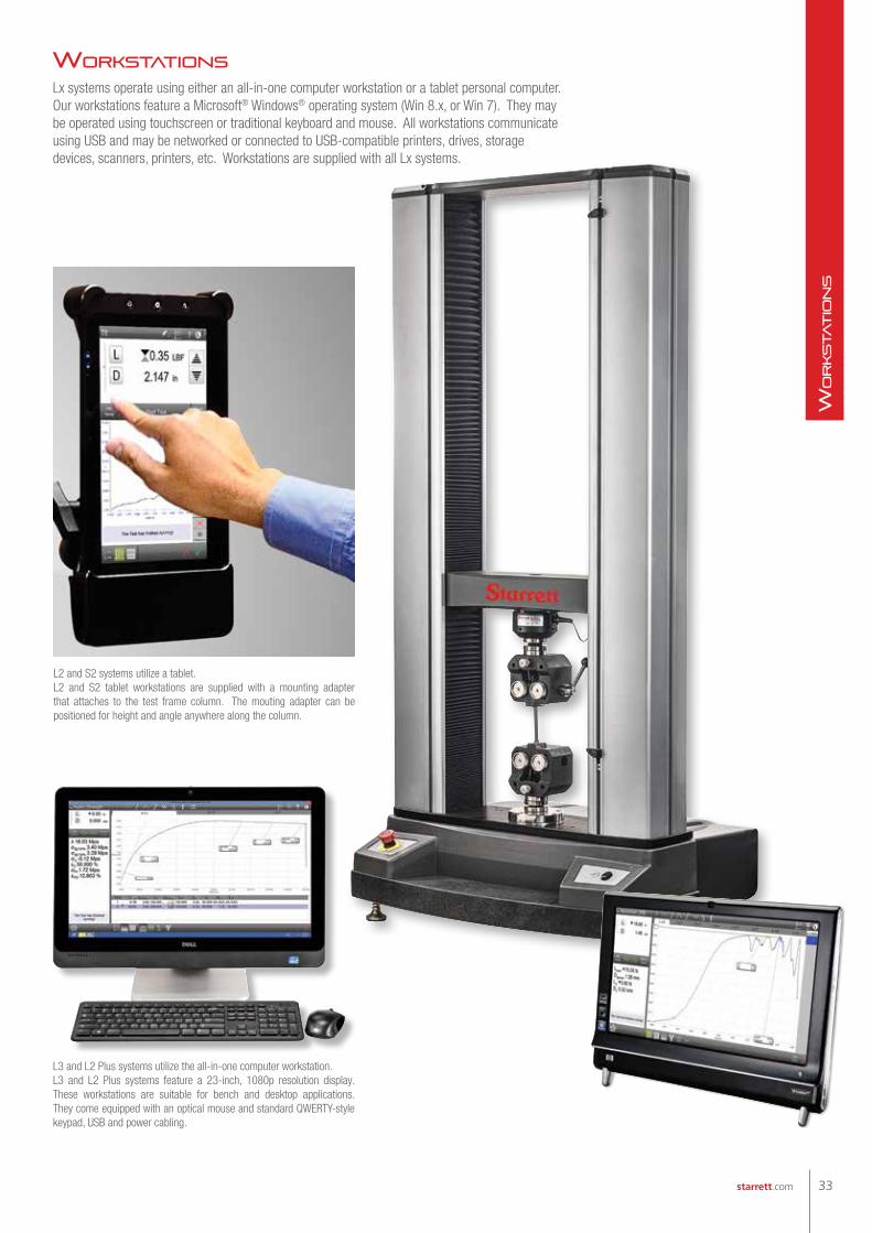
Lx systems operate using either an all-in-one computer workstation or a tablet personal computer. Our workstations feature a Microsoft® Windows® operating system (Win 8.x, or Win 7). They may be operated using touchscreen or traditional keyboard and mouse. All workstations communicate using USB and may be networked or connected to USB-compatible printers, drives, storage devices, scanners, printers, etc. Workstations are supplied with all Lx systems.
L2 and S2 systems utilize a tablet.L2 and S2 tablet workstations are supplied with a mounting adapter that attaches to the test frame column. The mouting adapter can be positioned for height and angle anywhere along the column.
L3 and L2 Plus systems utilize the all-in-one computer workstation.L3 and L2 Plus systems feature a 23-inch, 1080p resolution display. These workstations are suitable for bench and desktop applications. They come equipped with an optical mouse and standard QWERTY-style keypad, USB and power cabling.
workstations
33starrett.com
workstatio
ns

Follow us!
(978) 249-3551 • starrett.com
Pure Precision.
Introducing the HDV300 Video-based
measurement system. The power of an
optical comparator, meets the precision
of digital video.
Precision makes the Difference

Load Cell Sensors
ULC Series - "Ultra" Low Profile Sensors
Model NumberLoad Capacity Safe Overload Full Scale Deflection Height1 Width ThreadN KGF LBF % Full Scale mm inch mm inch mm inch mm
ULC-1500 1500 150 337 150 0.05 0.002 63.5 2.5 104.8 4.13 M16 x 2-4HULC-2500 2500 250 567 150 0.05 0.002 63.5 2.5 104.8 4.13 M16 x 2-4HULC-5K 5000 500 1124 150 0.05 0.002 63.5 2.5 104.8 4.13 M16 x 2-4HULC-10K 10,000 1000 2248 150 0.05 0.002 63.5 2.5 104.8 4.13 M16 x 2-4HULC-25K 25,000 2500 5620 150 0.05 0.002 63.5 2.5 104.8 4.13 M16 x 2-4HULC-50K 50,000 5000 11,250 150 0.05 0.002 63.5 2.5 104.8 4.13 M16 x 2-4HNOTES1 Dimension includes the base adapter. ULC Series sensors are supplied with the base adapter standard.
Load measurement accuracy is ±0.05% of reading down to 1/100 of load cell capacity. Display resolution is 10,000:1.Starrett recommends on-site verification of accuracy during installation. Sensor calibration should be performed at least annually.
MLC Series - Low Profile Sensors
Model NumberLoad Capacity Safe Overload Full Scale Deflection Height1 Width ThreadN KGF LBF % Full Scale mm inch mm inch mm inch mm
MLC-125 125 12.5 28 150 0.08 0.003 38.1 1.5 69.8 2.75 M6 x 1-6HMLC-250 250 25 56 150 0.08 0.003 38.1 1.5 69.8 2.75 M6 x 1-6HMLC-500 500 50 112 150 0.08 0.003 38.1 1.5 69.8 2.75 M6 x 1-6HMLC-1000 1000 100 225 150 0.08 0.003 38.1 1.5 69.8 2.75 M6 x 1-6HMLC-1500 1500 150 337 150 0.03 0.001 63.51 2.51 104.8 4.13 M16 x 2-4HMLC-2500 2500 250 562 150 0.03 0.001 63.51 2.51 104.8 4.13 M16 x 2-4HMLC-5K 5000 500 1124 150 0.03 0.001 63.51 2.51 104.8 4.13 M16 x 2-4HMLC-10K 10,000 1000 2248 150 0.03 0.001 63.51 2.51 104.8 4.13 M16 x 2-4HMLC-25K 25,000 2500 5620 150 0.05 0.002 63.51 2.51 104.8 4.13 M16 x 2-4HMLC-50K 50,000 5000 11,250 150 0.05 0.002 63.51 2.51 104.8 4.13 M16 x 2-4HNOTES1 Dimension includes the base adapter. These MLC sensors are supplied with the base adapter standard. Base adapters are recommended for any MLC sensor.
Load measurement accuracy is ±0.05% of reading down to 1/100 of load cell capacity. Display resolution is 10,000:1.Starrett recommends on-site verification of accuracy during installation. Sensor calibration should be performed at least annually.
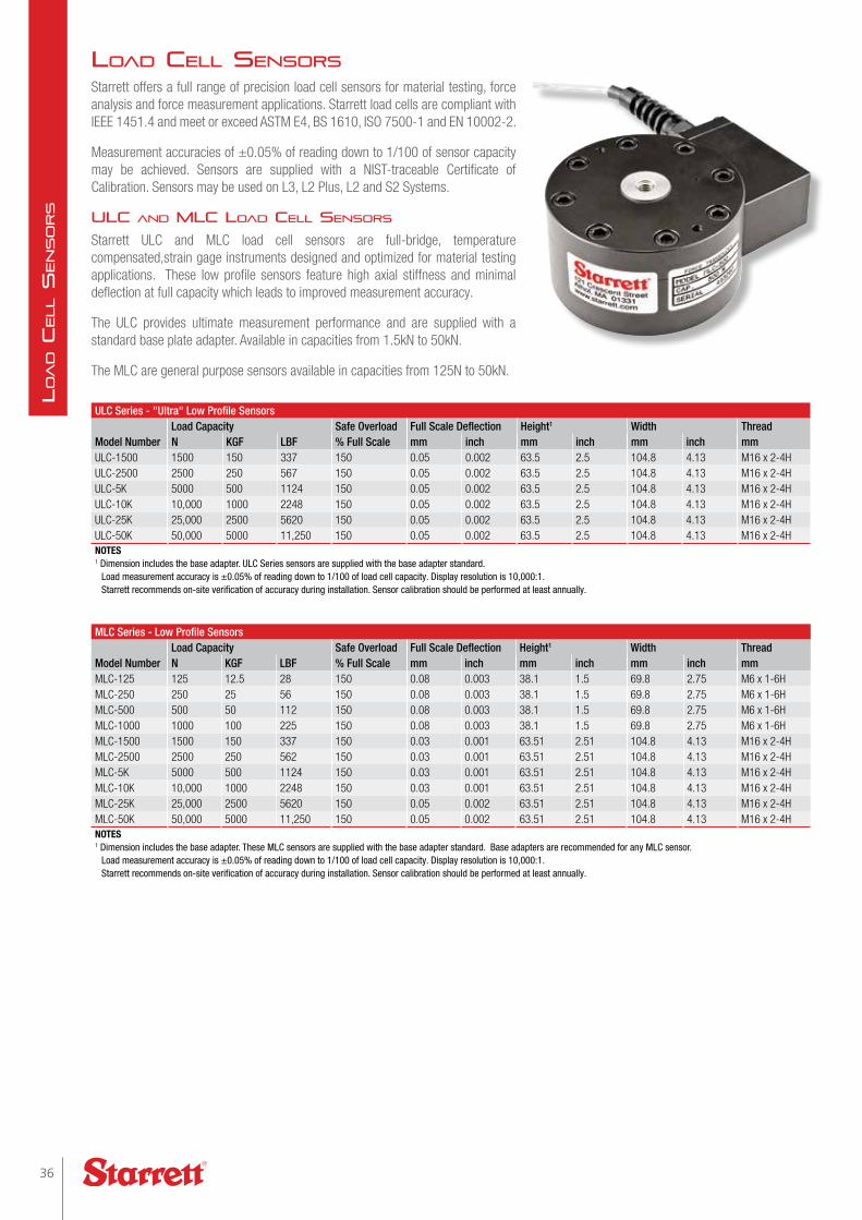
Starrett offers a full range of precision load cell sensors for material testing, force analysis and force measurement applications. Starrett load cells are compliant with IEEE 1451.4 and meet or exceed ASTM E4, BS 1610, ISO 7500-1 and EN 10002-2.
Measurement accuracies of ±0.05% of reading down to 1/100 of sensor capacity may be achieved. Sensors are supplied with a NIST-traceable Certificate of Calibration. Sensors may be used on L3, L2 Plus, L2 and S2 Systems.
uLc and mLc Load ceLL sensors
Starrett ULC and MLC load cell sensors are full-bridge, temperature compensated,strain gage instruments designed and optimized for material testing applications. These low profile sensors feature high axial stiffness and minimal deflection at full capacity which leads to improved measurement accuracy.
The ULC provides ultimate measurement performance and are supplied with a standard base plate adapter. Available in capacities from 1.5kN to 50kN.
The MLC are general purpose sensors available in capacities from 125N to 50kN.
Load ceLL sensors
36
Loa
d C
eLL S
en
So
rS

FLC-P Series - "Premium" S-beam Sensors
Model NumberLoad Capacity Safe Overload Full Scale Deflection Height Width ThreadN KGF LBF % Full Scale mm inch mm inch mm inch mm
FLC-5P 5 0.5 1 1000 0.4 0.014 63.0 2.48 59.2 2.33 M6 x 1-6HFLC-10P 10 1 2 1000 0.3 0.012 63.0 2.48 59.2 2.33 M6 x 1-6HFLC-25P 25 2.5 5 1000 0.3 0.012 63.0 2.48 59.2 2.33 M6 x 1-6HFLC-50P 50 5 11 1000 0.2 0.009 63.0 2.48 59.2 2.33 M6 x 1-6HFLC-100P 100 10 22 1000 0.2 0.009 63.0 2.48 59.2 2.33 M6 x 1-6HFLC-250P 250 25 56 1000 0.2 0.009 63.0 2.48 59.2 2.33 M6 x 1-6HNOTESLoad measurement accuracy is ±0.1% of load cell capacity. Display resolution is 10,000:1.Starrett recommends on-site verification of accuracy during installation. Sensor calibration should be performed at least annually.
FLC Series - "Sealed" S-beam Sensors
Model NumberLoad Capacity Safe Overload Full Scale Deflection Height Width ThreadN KGF LBF % Full Scale mm inch mm inch mm inch mm
FLC-500 500 50 112 150 0.10 0.004 63.0 2.5 50.8 2.0 M6 x 1-6HFLC-1000 1000 100 225 150 0.15 0.006 63.0 2.5 50.8 2.0 M6 x 1-6HFLC-2000 2000 200 450 150 0.13 0.005 76.2 3.0 50.8 2.0 M12 x 1.75-5HFLC-2500 2500 250 562 150 0.13 0.005 76.2 3.0 50.8 2.0 M12 x 1.75-5HFLC-5KN 5000 500 1124 150 0.13 0.005 76.2 3.0 50.8 2.0 M12 x 1.75-5HFLC-10K 10,000 1000 2248 150 0.13 0.005 76.2 3.0 50.8 2.0 M12 x 1.75-5HFLC-20K 20,000 2000 4500 150 0.13 0.005 88.9 3.5 63.5 3.5 M16 x 2-4HNOTESLoad measurement accuracy is ±0.1% of load cell capacity. Display resolution is 10,000:1.Starrett recommends on-site verification of accuracy during installation. Sensor calibration should be performed at least annually.
FLC-E Series - "Economy" S-beam Sensors
Model NumberLoad Capacity Safe Overload Full Scale Deflection Height Width ThreadN KGF LBF % Full Scale mm inch mm inch mm inch mm
FLC-50E 50 5 11 150 0.08 0.003 63.5 2.5 50.8 2.0 M6 x 1-6HFLC-100E 100 10 22 150 0.08 0.003 63.5 2.5 50.8 2.0 M6 x 1-6HFLC-200E 200 20 45 150 0.08 0.003 63.5 2.5 50.8 2.0 M6 x 1-6HFLC-500E 500 50 112 150 0.10 0.004 63.5 2.5 50.8 2.0 M6 x 1-6HFLC-1000E 1000 100 225 150 0.15 0.006 63.5 2.5 50.8 2.0 M6 x 1-6HFLC-2000E 2000 200 450 150 0.15 0.006 76.2 3.0 50.8 2.0 M12 x 1.75-5HFLC-2500E 2500 250 562 150 0.13 0.005 76.2 3.0 50.8 2.0 M12 x 1.75-5HFLC-5000E 5000 500 1124 150 0.13 0.005 76.2 3.0 50.8 2.0 M12 x 1.75-5HNOTESLoad measurement accuracy is ±0.1% of load cell capacity. Display resolution is 10,000:1.Starrett recommends on-site verification of accuracy during installation. Sensor calibration should be performed at least annually.
FLc Load ceLL sensors
Three models of s-beam load cell sensors are also available. These are all full bridge, temperature compensated strain gage instruments, designed for force measurement applications, but suitable for some material testing applications.
Premium modeLs
Ideal for low load applications, these sensors have a safe overload rating of 1000% of the sensor's load capacity.
seaLed modeLs
These models are suitable for applications in non-laboratory environments where dirt, oil, dust and debris may be present.
economy modeLs
When price is an issue, these general purpose load cell sensors are economical and suitable for most general purpose force measurement applications.
Load ceLL sensors
37starrett.com
Loa
d C
eLL S
en
So
rS

accessories
test Fixtures
Starrett offers a full range of test fixtures, grips and accessories. Test fixtures are compatible with all Starrett systems and test frames. Starrett can also engineer and supply custom test fixtures to your exact requirements.
tyPes
• Button Head
• Compression Cages
• Flexural
• Hydraulic
• Peel
• Platens
• Pneumatic
• Ribbon
• Roller
• Scissor
• Shear
• Vice-action
• Wedge-action
sPecimen dies
Dies are available for testing a variety of materials including rubber, plastic, elastomer, fabric, paper, films and more. Dies are engineered to comply with common testing standards including:
• ASTM D-412 (A,B,C,D,F)
• ASTM D-638 (I, II, III, IV, V)
• ISO 34 (A,B)
• BS 6746
• IEC 540
Starrett can supply a wide assortment of testing fixtures that comply with international testing standards from ASTM, ISO, DIN, TAPPI and more. We can also supply custom test fixtures for difficult sample shapes.
Starrett specimen dies help ensure accurate dimensions for your sample preparations.
test Fixtures, extensometers, shieLds
38
Accesso
rie
s
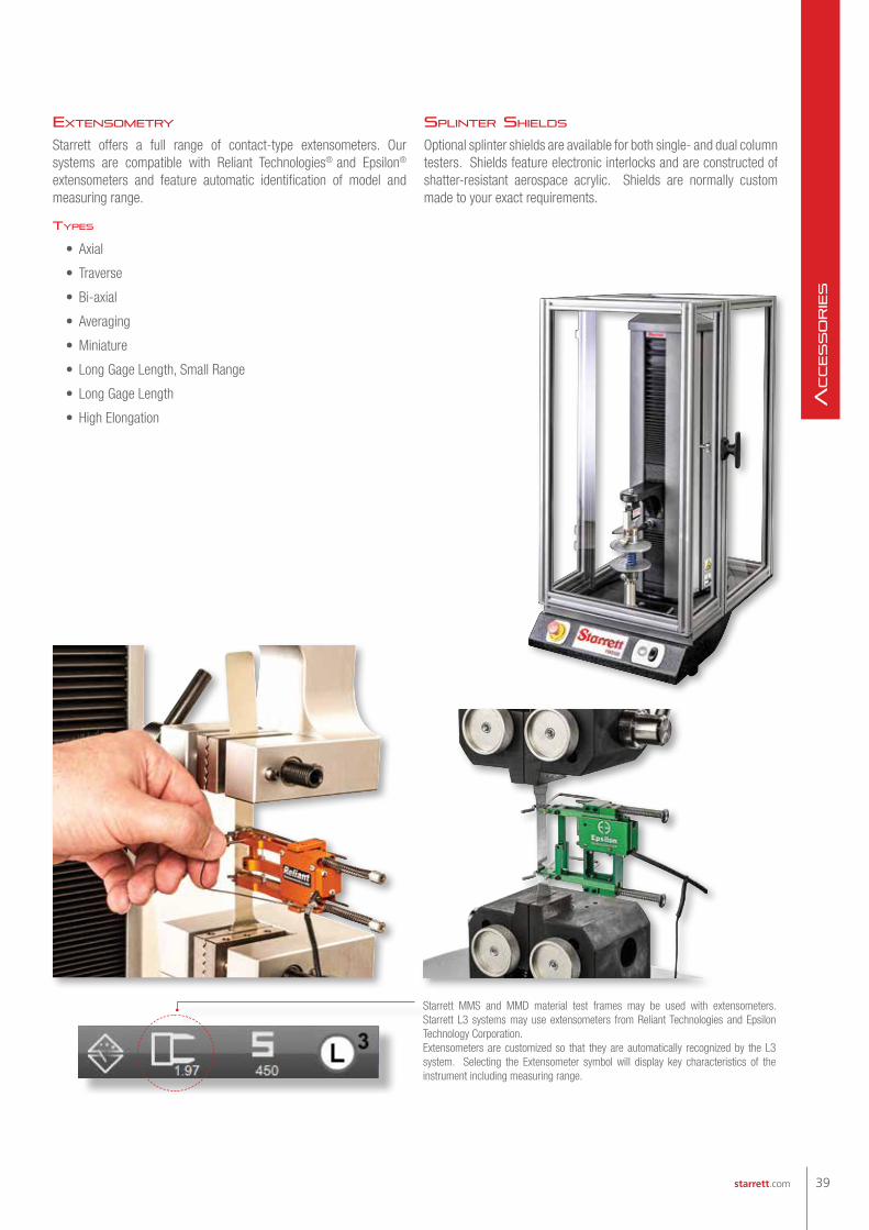
extensometry
Starrett offers a full range of contact-type extensometers. Our systems are compatible with Reliant Technologies® and Epsilon® extensometers and feature automatic identification of model and measuring range.
tyPes
• Axial
• Traverse
• Bi-axial
• Averaging
• Miniature
• Long Gage Length, Small Range
• Long Gage Length
• High Elongation
sPLinter shieLds
Optional splinter shields are available for both single- and dual column testers. Shields feature electronic interlocks and are constructed of shatter-resistant aerospace acrylic. Shields are normally custom made to your exact requirements.
Starrett MMS and MMD material test frames may be used with extensometers. Starrett L3 systems may use extensometers from Reliant Technologies and Epsilon Technology Corporation.Extensometers are customized so that they are automatically recognized by the L3 system. Selecting the Extensometer symbol will display key characteristics of the instrument including measuring range.
39starrett.com
Accesso
rie
s

Follow us!
(978) 249-3551 • starrett.com
For over 130 years,
with innovative
technologies.
More than 5,000 products including
precision tools, vision systems, force
measurement systems, non-contact
measurement systems, profile
projectors, band saw blades, band
saw machines, hand tools and
power tools accessories.
Read more: www.starrett.com
Precision makes the Difference

Applications, Services and Software
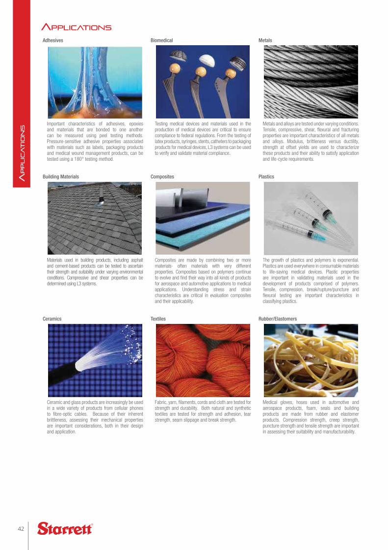
aPPLications Adhesives Biomedical Metals
Important characteristics of adhesives, epoxies and materials that are bonded to one another can be measured using peel testing methods. Pressure-sensitive adhesive properties associated with materials such as labels, packaging products and medical wound management products, can be tested using a 180° testing method.
Testing medical devices and materials used in the production of medical devices are critical to ensure compliance to federal regulations. From the testing of latex products, syringes, stents, catheters to packaging products for medical devices, L3 systems can be used to verify and validate material compliance.
Metals and alloys are tested under varying conditions. Tensile, compressive, shear, flexural and fracturing properties are important characteristics of all metals and alloys. Modulus, brittleness versus ductility, strength at offset yields are used to characterize these products and their ability to satisfy application and life-cycle requirements.
Building Materials Composites Plastics
Materials used in building products, including asphalt and cement-based products can be tested to ascertain their strength and suitability under varying environmental conditions. Compressive and shear properties can be determined using L3 systems.
Composites are made by combining two or more materials- often materials with very different properties. Composites based on polymers continue to evolve and find their way into all kinds of products for aerospace and automotive applications to medical applications. Understanding stress and strain characteristics are critical in evaluation composites and their applicability.
The growth of plastics and polymers is exponential. Plastics are used everywhere in consumable materials to life-saving medical devices. Plastic properties are important in validating materials used in the development of products comprised of polymers. Tensile, compression, break/rupture/puncture and flexural testing are important characteristics in classifying plastics.
Ceramics Textiles Rubber/Elastomers
Ceramic and glass products are increasingly be used in a wide variety of products from cellular phones to fibre-optic cables. Because of their inherent brittleness, assessing their mechanical properties are important considerations, both in their design and application.
Fabric, yarn, filaments, cords and cloth are tested for strength and durability. Both natural and synthetic textiles are tested for strength and adhesion, tear strength, seam slippage and break strength.
Medical gloves, hoses used in automotive and aerospace products, foam, seals and building products are made from rubber and elastomer products. Compression strength, creep strength, puncture strength and tensile strength are important in assessing their suitability and manufacturability.
42
Applic
Atio
ns

aPPLications common test method standards PerFormed usinG L3 systems
A370
A48
A615
A746
A938
A996
B557
C109
C1550
C1609
C165
C170
C192
C297
C31
C39
C42
C469
C633
C78
C880
C99
D256
D1002
D1004
D1047
D1238
D1335
D1414
D143
D1525
D1621
D1708
D1761
D1876
D1894
D2256
D2261
D2444
D2844
D3039
D2043
D3163
D3364
D3763
D3822
D3835
D3846
D4018
D412
D413
D4268
D429
D4632
D5034
D5035
D5083
D5250
D5587
D575
D5766
D5930
D6610
D6272
D6319
D638
D648
D695
D7136
D7137
D7192
D7269
D790
D882
D885
D903
D905
E1012
E119
E1290
E18
E1820
E190
E208
E21
E23
E290
E399
E517
E646
E8
E813
E9
F1306
F1614
F1714
F1717
F2063
F2077
F2079
F2255
F2256
F2258
F2267
F2346
F2412
F2458
F2477
F2516
F2606
F382
F384
F543
F606
F88
astm test methods
10319
11193-1
11193-2
1133
11339
11343
11443
11897
12737
13007-2
13934-1
13934-2
13937-2
13937-3
13937-4
14125
14126
14129
14130
1421
148
14801
14879
15630-1
15630-3
16402
17744
178
179-1
179-2
1798
180
1926
2062
20795-1
20795-2
2307
2411
306
3133
3183
34-1
36
37
4587
527-1
527-2
527-3
527-4
527-5
604
6238
6383-1
6475
6603-1
6603-2
6872
6892-1
6892-2
7206-4
7206-6
7206-8
7438
75
75-1
75-2
7800
7886-1
8067
813
8256-A
8295
844
9073-4
iso test methods
43starrett.com
Applic
Atio
ns
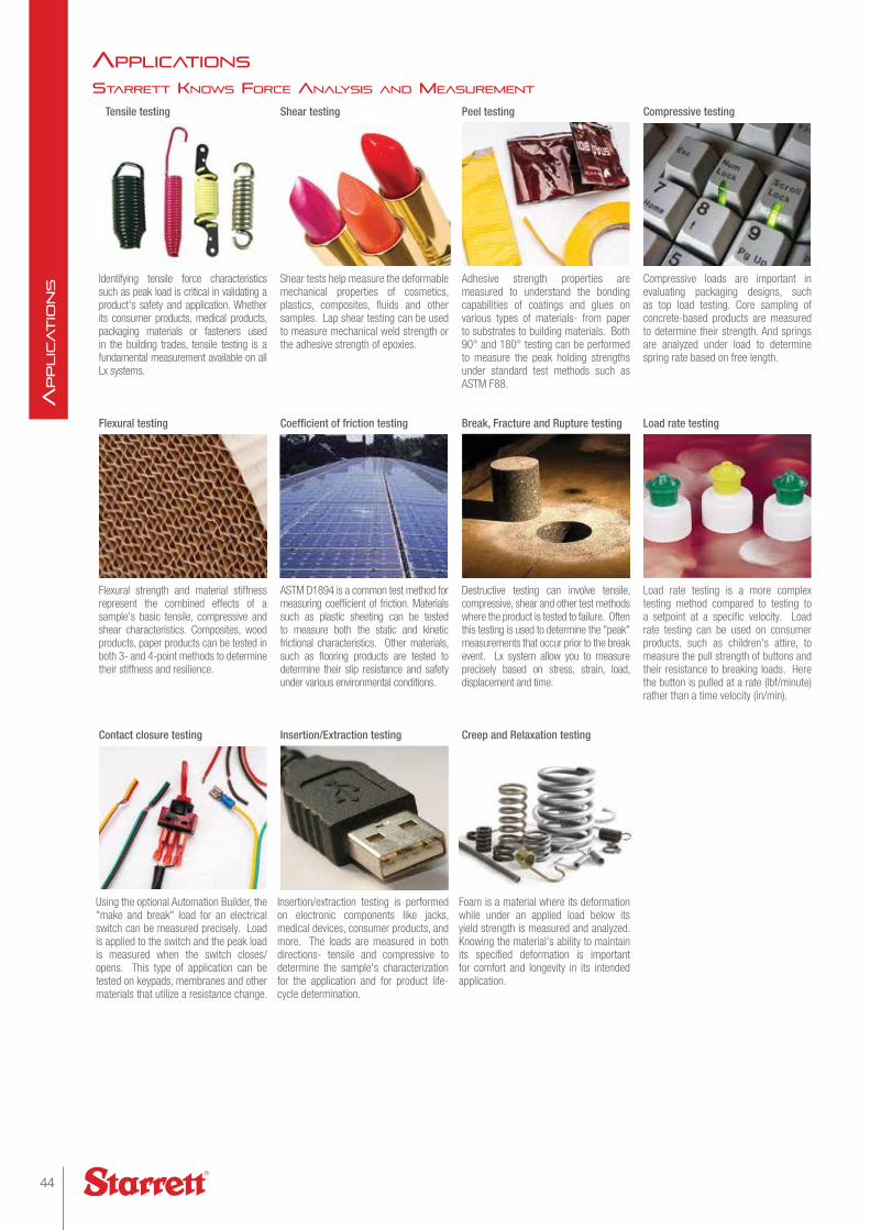
starrett knows Force anaLysis and measurement
Tensile testing Shear testing Peel testing Compressive testing
Identifying tensile force characteristics such as peak load is critical in validating a product's safety and application. Whether its consumer products, medical products, packaging materials or fasteners used in the building trades, tensile testing is a fundamental measurement available on all Lx systems.
Shear tests help measure the deformable mechanical properties of cosmetics, plastics, composites, fluids and other samples. Lap shear testing can be used to measure mechanical weld strength or the adhesive strength of epoxies.
Adhesive strength properties are measured to understand the bonding capabilities of coatings and glues on various types of materials- from paper to substrates to building materials. Both 90° and 180° testing can be performed to measure the peak holding strengths under standard test methods such as ASTM F88.
Compressive loads are important in evaluating packaging designs, such as top load testing. Core sampling of concrete-based products are measured to determine their strength. And springs are analyzed under load to determine spring rate based on free length.
Flexural testing Coefficient of friction testing Break, Fracture and Rupture testing Load rate testing
Flexural strength and material stiffness represent the combined effects of a sample's basic tensile, compressive and shear characteristics. Composites, wood products, paper products can be tested in both 3- and 4-point methods to determine their stiffness and resilience.
ASTM D1894 is a common test method for measuring coefficient of friction. Materials such as plastic sheeting can be tested to measure both the static and kinetic frictional characteristics. Other materials, such as flooring products are tested to determine their slip resistance and safety under various environmental conditions.
Destructive testing can involve tensile, compressive, shear and other test methods where the product is tested to failure. Often this testing is used to determine the "peak" measurements that occur prior to the break event. Lx system allow you to measure precisely based on stress, strain, load, displacement and time.
Load rate testing is a more complex testing method compared to testing to a setpoint at a specific velocity. Load rate testing can be used on consumer products, such as children's attire, to measure the pull strength of buttons and their resistance to breaking loads. Here the button is pulled at a rate (lbf/minute) rather than a time velocity (in/min).
Contact closure testing Insertion/Extraction testing Creep and Relaxation testing
Using the optional Automation Builder, the "make and break" load for an electrical switch can be measured precisely. Load is applied to the switch and the peak load is measured when the switch closes/opens. This type of application can be tested on keypads, membranes and other materials that utilize a resistance change.
Insertion/extraction testing is performed on electronic components like jacks, medical devices, consumer products, and more. The loads are measured in both directions- tensile and compressive to determine the sample's characterization for the application and for product life-cycle determination.
Foam is a material where its deformation while under an applied load below its yield strength is measured and analyzed. Knowing the material's ability to maintain its specified deformation is important for comfort and longevity in its intended application.
aPPLications
44
Applic
Atio
ns
PackaGinG testinG
T-Peel
90° Peel
180° Peel
Solder Paste Tackiness
ASTM F1140 - Burst Strength
ASTM D2659 - Top Load
ASTM F88 - Seal Strength
EN 868-5 - Seal Strength Pouches
ASTM C633 -Adhesion Spray Coating
ASTM D1335 - Tuft Binding Floor Covering
ASTM D903 - Adhesive Bond
ASTM D1876 - Peel Resistance
ISO 36 - Rubber Adhesion
ISO 2411 - Adhesion Plastic
ISO 4587 - Lap Shear Strength
ISO 11339 - Flexible Bond Assembly
EN 1465 - Lap Shear Strength
EN 1719 - Tack Measurement
EN 1939 - Peel Adhesion
Component Testing
Compress (Load/Extension)
Compress (Stress/Strain)
Indentation (Load/Extension)
Indentation (Stress/Strain)
Spring Rate
Spring Force
Spring Height
medicaL device testinG
ASTM F88 - Seal Strength
ASTM F382 - Metallic Bone Plates
ASTM F451 - Bone Cement Strength
ASTM F564 - Metallic Bone Staples
ASTM F1828 - Ureteral Stents
ASTM F1839 - Foam Devices
ASTM F1874 - Sutures Bend Test
ASTM F2079 - Stents Tensile Strength
ASTM F2132 - Puncture Resistance
ASTM F2183 - Punch Testing
ASTM F2255 - Lap Shear Testing
ASTM F2256 - Tissue Adhesives
ASTM F2258 - Tissue Adhesives
ASTM F2392 - Burst Strength Sealant
ASTM F2458 - Closure Strength
ASTM F2477 - Stents Strength
ASTM F2502 - Plates and Screws
ASTM F2516 - Tensile Nitinol Wire
ASTM F2606 - Bend Vascular Stent
ASTM D6319 - Medical Gloves
BS EN 455-2 - Medical Gloves
ISO 7886-1 - Hypodermic Syringe
ISO 14879 - Tibial Trays
ISO 11193 - Medical Glove
comPression test
Tensile Test
Tensile Strength
ASTM D3039 - Tensile Carbon Fiber
ASTM D3846 - Shear Strength
ASTM D7269 - Aramid Cords
ASTM D6484 - Compressive Strength
ASTM D1055 - Flex Resistance
ASTM D3574 - Indention Deflection
ASTM D3574 - Foam Deflection
EN 14509 - Shear Strength
ISO 527-4 - Tensile Isotropic/Orthotropic
ISO 14125 - Flexural Properties
ISO 14126 - In-plane Compression
TAPPI - 404 - Tensile Break Strength
TAPPI 220 - Burst Strength
TAPPI 456 - Wet Paper Strength
TAPPI 457 - Pull to Rupture
aPPLications
45starrett.com
Applic
Atio
ns

services
Field and factory calibrations are performed by authorized Starrett service technicians to accepted industry standards and methodology. All calibra-tions are NIST-traceable.
Starrett stocks critical spare parts and accessories for quick delivery. Load cell sensors and commonly used test fixtures are readily available.
caLibration, FieLd service, Factory service
Starrett and our global network of service providers can provide all levels of service for your material test and force measurement systems. We can supply a comprehensive range of calibration and verification services to ensure that your testing meets the requirements of international testing standards. Calibrations can be performed to ASTM E4 for load and ASTM E2658 for displacement or to equivalent standards from ISO, BS, DIN and more. Speed, stress and strain verifications can be performed on-site by technicians accredited to ISO 17025.
Preventative maintenance programs, field and factory repair services are available to ensure that your systems perform to their published specifications.
Starrett can provide factory services including load cell calibrations, test frame repair and reconditioning. All Starrett load cell sensors are supplied with a NIST-traceable Certificate of Calibration.
Specialized services, including system integration with existing instrumentation, or application development for complex testing applications can be supplied by your Starrett representative.
Your Starrett representative can provide on-site training to your personnel to help ensure that your system operates to its published specification. Our training also provides your operators with the knowledge needed to perform your testing in a safe and efficient manner. Our objectives are to help you make your products better through improved resource utilization, increased throughput and optimized efficiency.
46
Serv
iceS
Lx System Product Comparisons and CapabilitiesTarget Applications L3 L2 Plus L2 S2Use for Stress, Strain and Material Testing applications m
Use for Advanced Load, Distance and Force Analysis applications m m
Use for Basic Load, Distance and Force Measurement applications m m m
Use for Advanced Extension and Compression Spring applications m m
Use for Basic Extension and Compression Spring applications m
User Interface
All-In-On Computer Workstation, Windows® OS m m
Tablet Computer, Windows® OS m m
Software Applications
Test Builder m m m
Force Quick Test Templates m
Spring Quick Test Templates m
Formula Builder m
Automation Builder
Measurement Methodology
Measure results using the graph m m
Measure results using a List of Value menu m m m m
Create Test Setups using Graphical Test Methods (No programming) m m m
Create Test Setups using Quick-Test Templates m m
Test Methods
Tensile Testing, Load, Distance, Break, Rate m m m
Compression Testing, Load, Distance, Break, Rate m m m
Hold Testing, Load, Distance for Duration or Event m m m
Cyclic Testing for Duration, Count, Loop or Event m m m
Shear Testing m m
Flexural Testing m m
Peel Testing m m
Coefficient of Friction Testing m m
Spring Testing m m m
Measurement Capabilities
Measure Stress, Strain, Elongation, Strengths m
Measure Offset Yield m
Measure Modulus (Elastic, Chord, Tangent) m
Measure Strain and Elongation using Extensometer(s) (requires MMx test frames) m
Measure Energy, Work, Resilience m m
Create Mathematical Expressions using Algebraic, Trigonometric and Logarithmic functions m w
Create Basic Expressions using Add, Subtract, Multiple and Divide m w w w
Use Digital I/O w w w w
Use Analog I/O (requires MMx test frames) w w
Use Command and Conditional Logic w w w w
Measure Load, Distance, Time m m m m
Measure Minimum, Maximum and Averages m m m m
Measure Slopes and Intersections m m
Measure Peaks, Valleys, Counts, Averages m m
Measure Break, Rupture m m m r
Measure Delta between results within a test m m m
Measure results within multiple test runs simultaneously (multiview) m m
Measure Spring Rate, Spring Constant m m m
Reporting and Exporting Data
Print using standard reports, graph, batch, tolerance, statistics m m m m
Export results/data in .csv for custom reporting m m m m
Export results/data in .csv for integration with SPC software m m m m
Include tolerances on any result m m m m
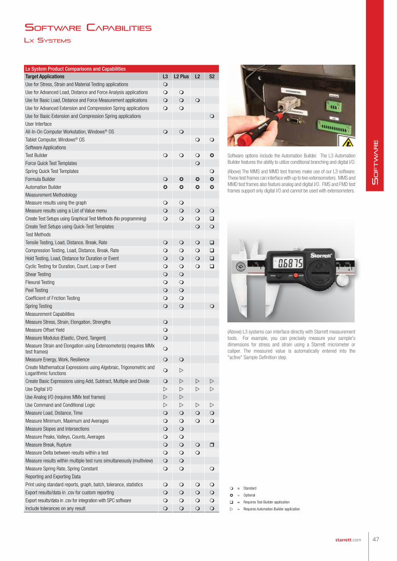
Lx systems
soFtware caPabiLities
Software options include the Automation Builder. The L3 Automation Builder features the ability to utilize conditional branching and digital I/O.
(Above) The MMS and MMD test frames make use of our L3 software. These test frames can interface with up to two extensometers. MMS and MMD test frames also feature analog and digital I/O. FMS and FMD test frames support only digital I/O and cannot be used with extensometers.
(Above) L3 systems can interface directly with Starrett measurement tools. For example, you can precisely measure your sample's dimensions for stress and strain using a Starrett micrometer or caliper. The measured value is automatically entered into the "active" Sample Definition step.
m = Standard
= Optional
= Requires Test Builder application
w = Requires Automation Builder application
47starrett.com
So
ftw
are
