forces in structures and machinesusers.metu.edu.tr/sonmez/mech 100/forces in structures and...
TRANSCRIPT
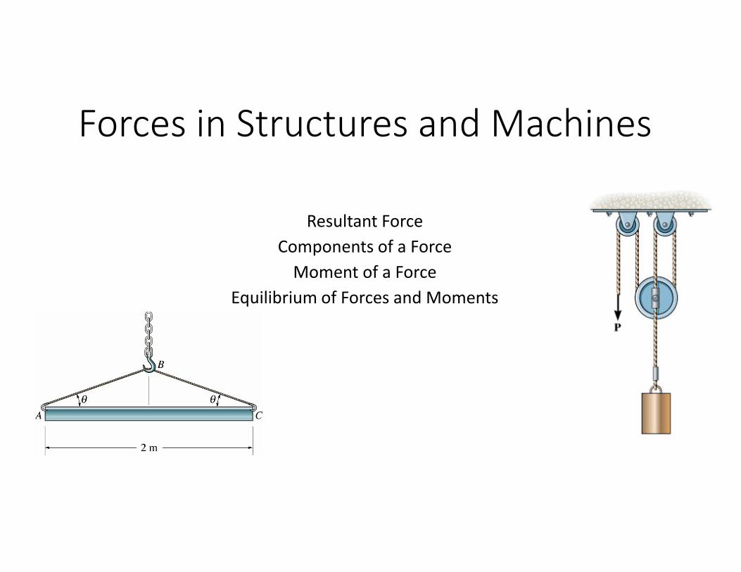
Forces in Structures and Machines
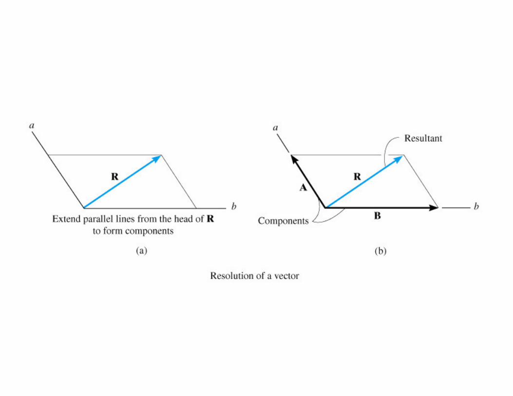
Resultant Force
Components of a Force
Moment of a Force
Equilibrium of Forces and Moments
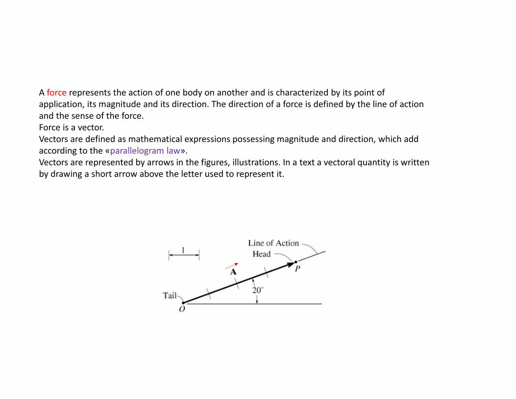
A force represents the action of one body on another and is characterized by its point of
application, its magnitude and its direction. The direction of a force is defined by the line of action
and the sense of the force.
Force is a vector.
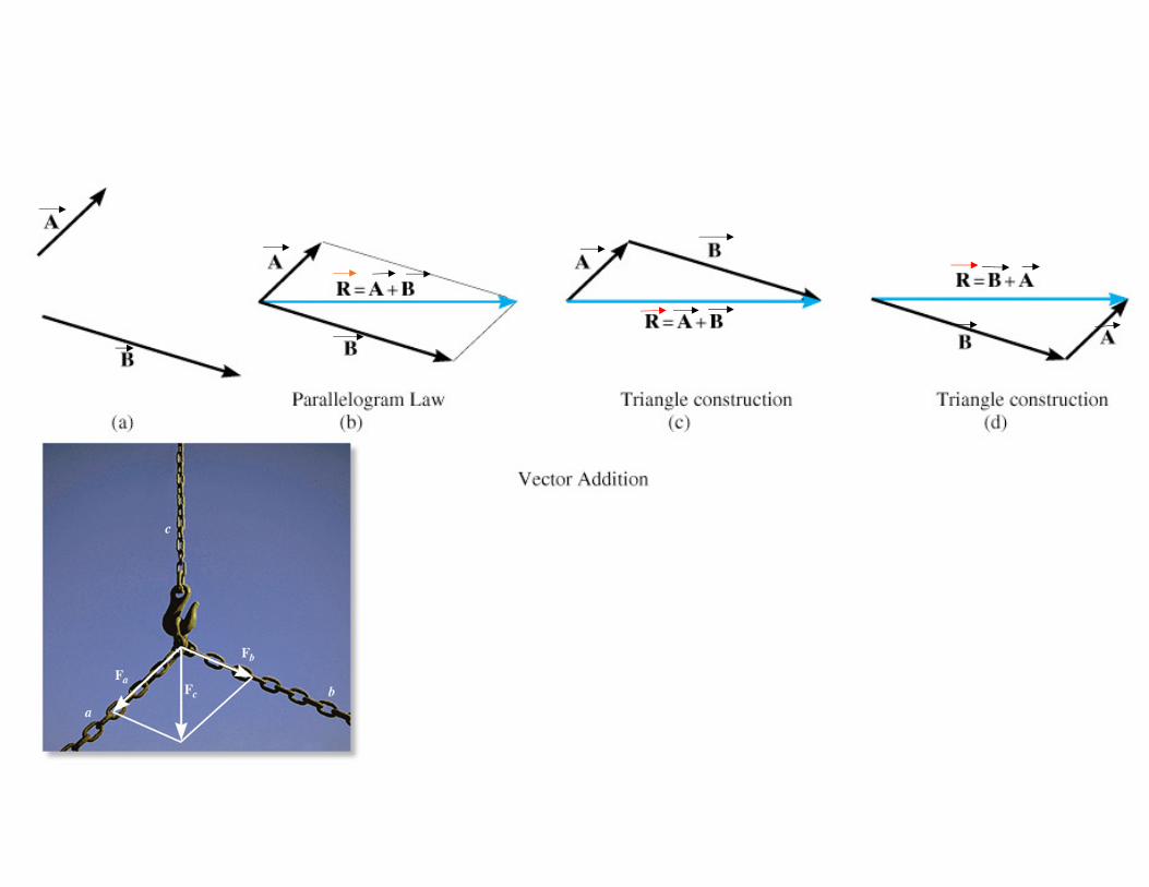
Vectors are defined as mathematical expressions possessing magnitude and direction, which add
according to the «parallelogram law».
Vectors are represented by arrows in the figures, illustrations. In a text a vectoral quantity is written
by drawing a short arrow above the letter used to represent it.
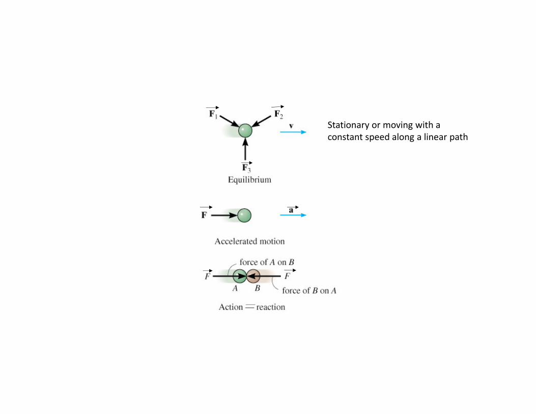
Stationary or moving with a
constant speed along a linear path


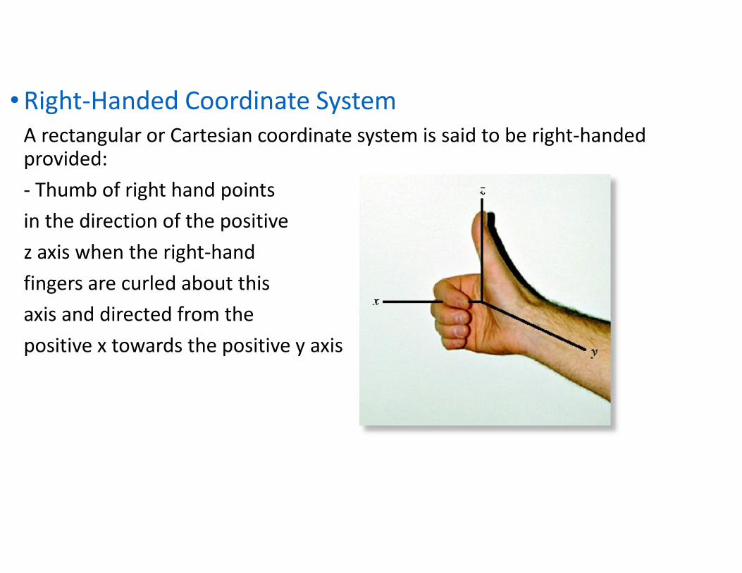
• Right-Handed Coordinate System
A rectangular or Cartesian coordinate system is said to be right-handed provided:
- Thumb of right hand points
in the direction of the positive
z axis when the right-hand
fingers are curled about this
axis and directed from the
positive x towards the positive y axis
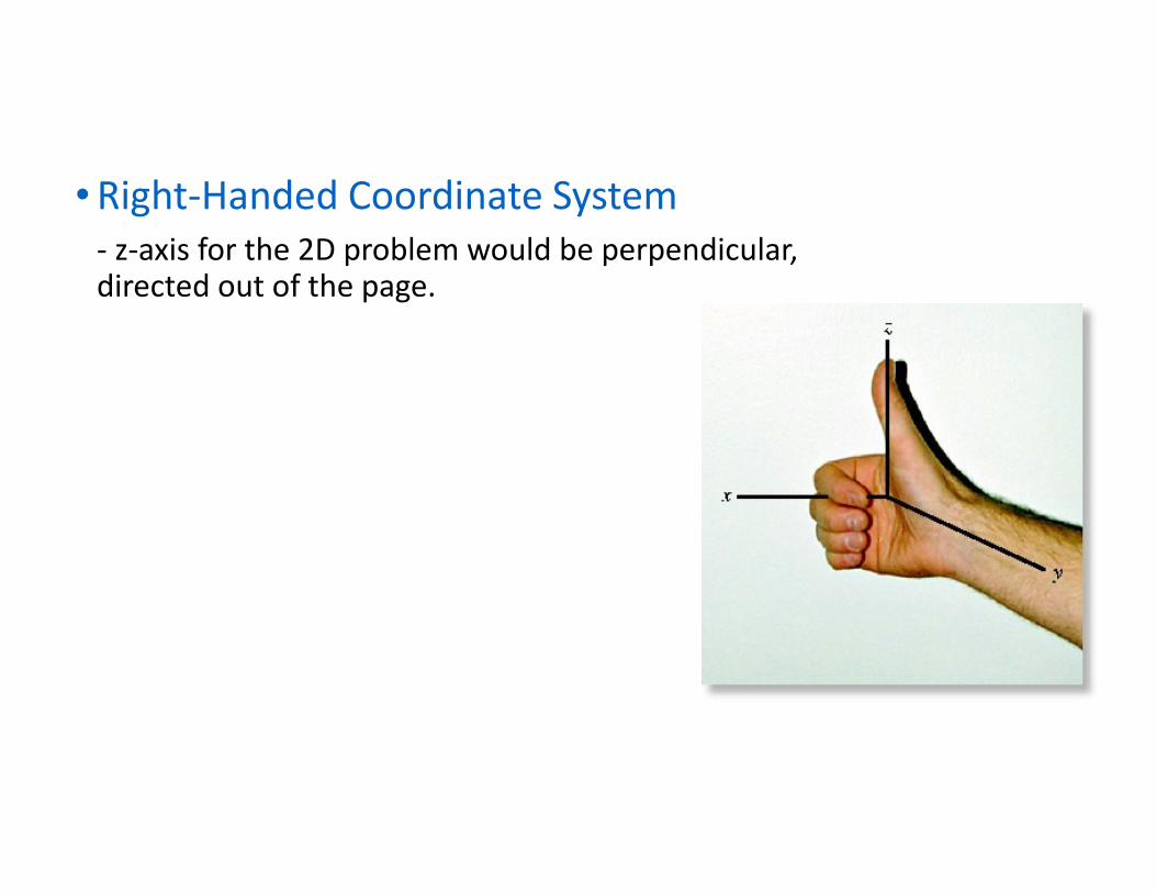
• Right-Handed Coordinate System
- z-axis for the 2D problem would be perpendicular, directed out of the page.
Cartesian Vectors
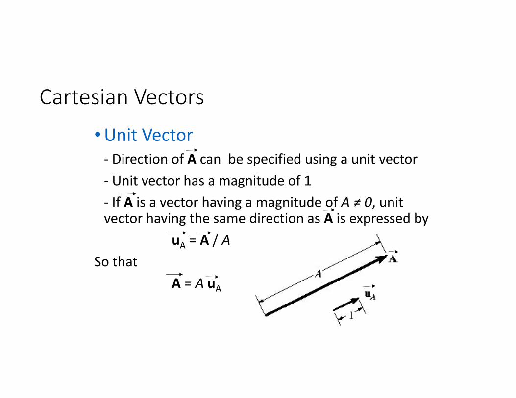
• Unit Vector
- Direction of A can be specified using a unit vector
- Unit vector has a magnitude of 1
- If A is a vector having a magnitude of A ≠ 0, unit vector having the same direction as A is expressed by
uA = A / A
So that
A = A uA
2.5 Cartesian Vectors
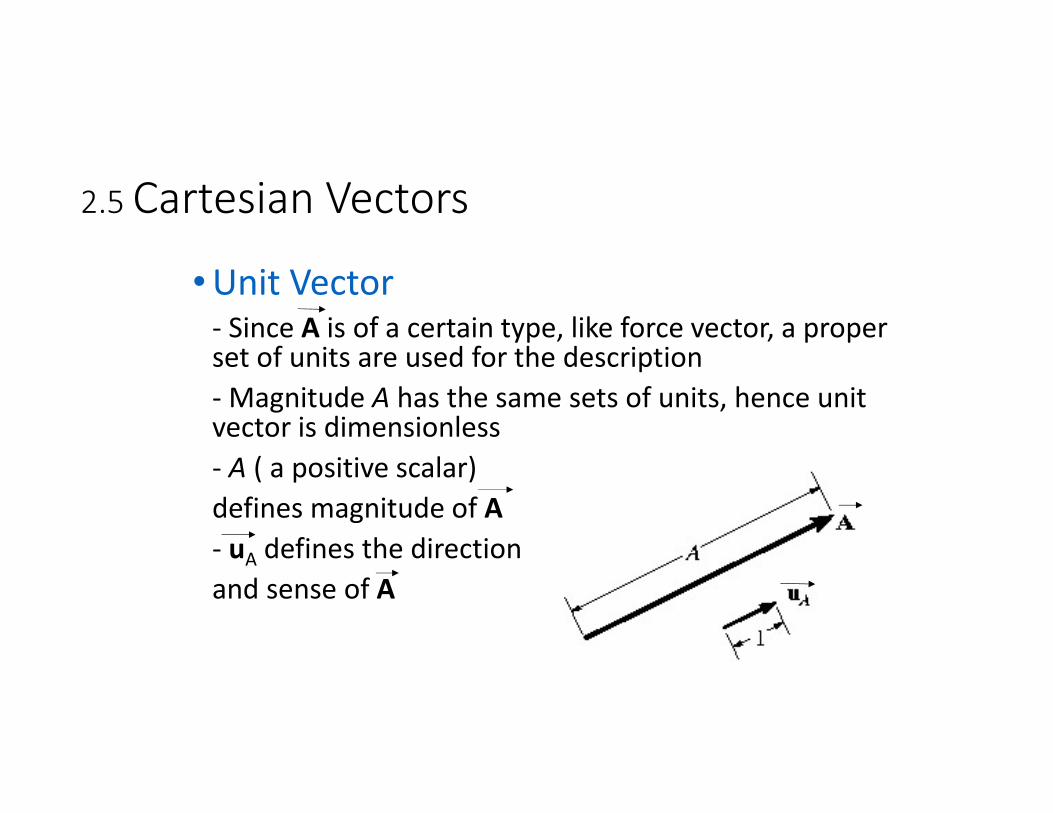
• Unit Vector- Since A is of a certain type, like force vector, a proper set of units are used for the description
- Magnitude A has the same sets of units, hence unit vector is dimensionless
- A ( a positive scalar)
defines magnitude of A
- uA defines the direction
and sense of A
Cartesian Vectors
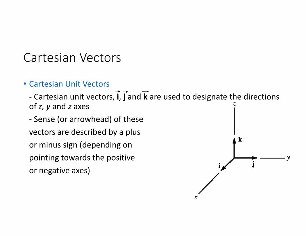
• Cartesian Unit Vectors
- Cartesian unit vectors, i, j and k are used to designate the directions of z, y and z axes
- Sense (or arrowhead) of these
vectors are described by a plus
or minus sign (depending on
pointing towards the positive
or negative axes)
Cartesian Vectors
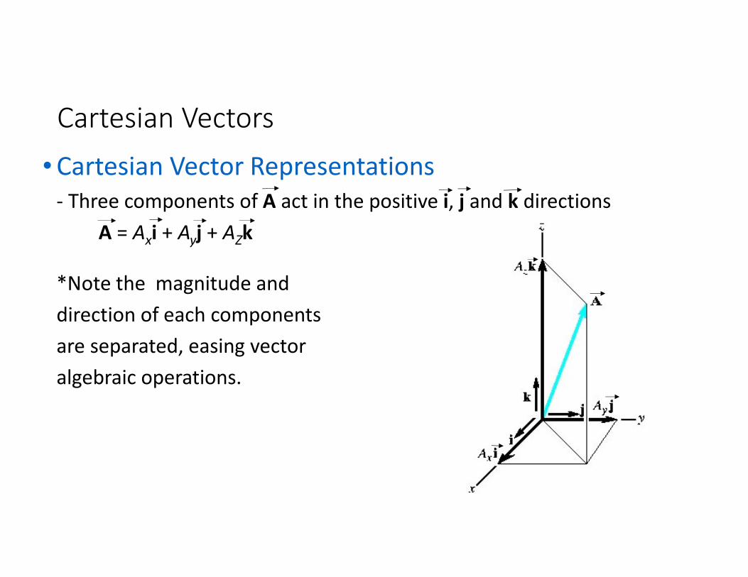
• Cartesian Vector Representations
- Three components of A act in the positive i, j and k directions
A = Axi + Ayj + AZk
*Note the magnitude and
direction of each components
are separated, easing vector
algebraic operations.
Cartesian Vectors
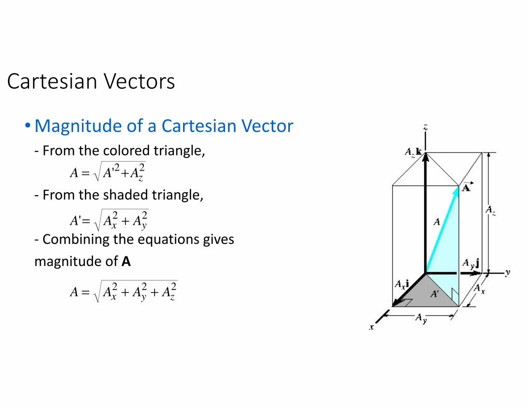
• Magnitude of a Cartesian Vector
- From the colored triangle,
- From the shaded triangle,
- Combining the equations gives
magnitude of A
222
22
22
'
'
zyx
yx
z
AAAA
AAA
AAA
++=
+=
+=

Cartesian Vectors
• Direction of a Cartesian Vector
- Orientation of A is defined as the coordinate direction angles α, β and γmeasured between the tail of A and the positive x, y and z axes
- 0° ≤ α, β and γ ≤ 180 °
Direction angles: a, b, gDirection Cosines: cos �, cos �, cos �
Cartesian Vectors
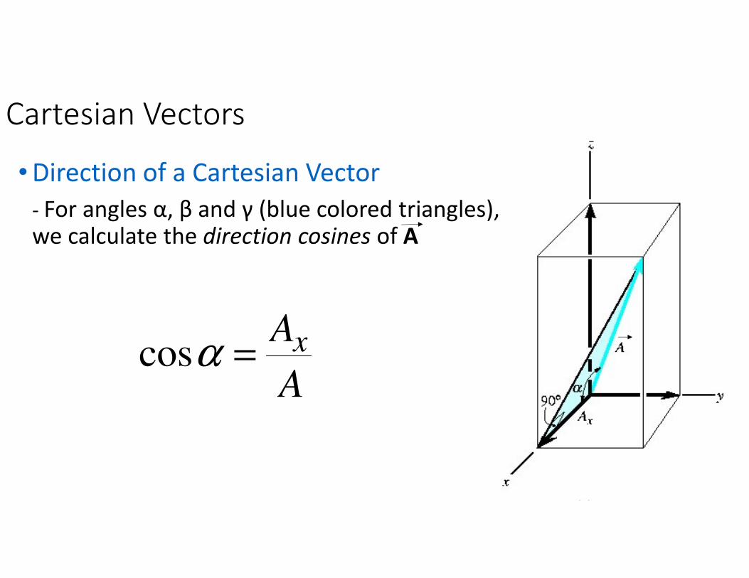
• Direction of a Cartesian Vector
- For angles α, β and γ (blue colored triangles), we calculate the direction cosines of A
A
Ax=αcos

Cartesian Vectors
• Direction of a Cartesian Vector
- For angles α, β and γ (blue colored triangles), we calculate the direction cosines of A
A
Ay=βcos
Cartesian Vectors
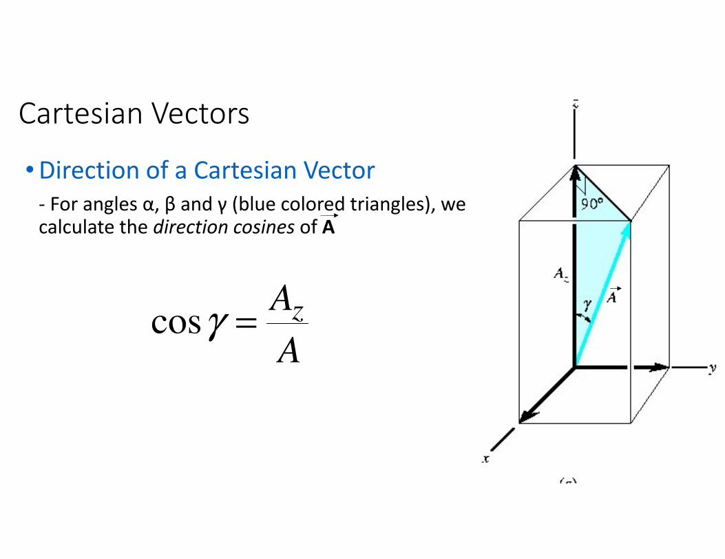
• Direction of a Cartesian Vector
- For angles α, β and γ (blue colored triangles), we calculate the direction cosines of A
A
Az=γcos
Cartesian Vectors
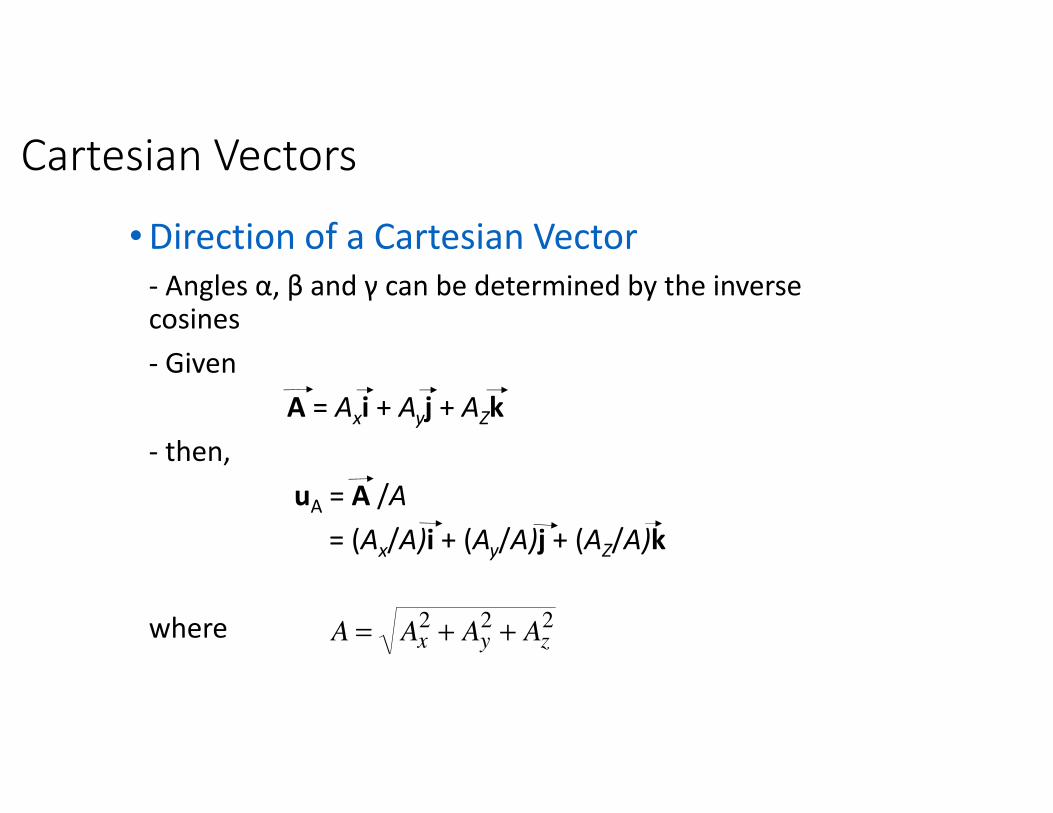
• Direction of a Cartesian Vector
- Angles α, β and γ can be determined by the inverse cosines
- Given
A = Axi + Ayj + AZk
- then,
uA = A /A
= (Ax/A)i + (Ay/A)j + (AZ/A)k
where 222
zyx AAAA ++=
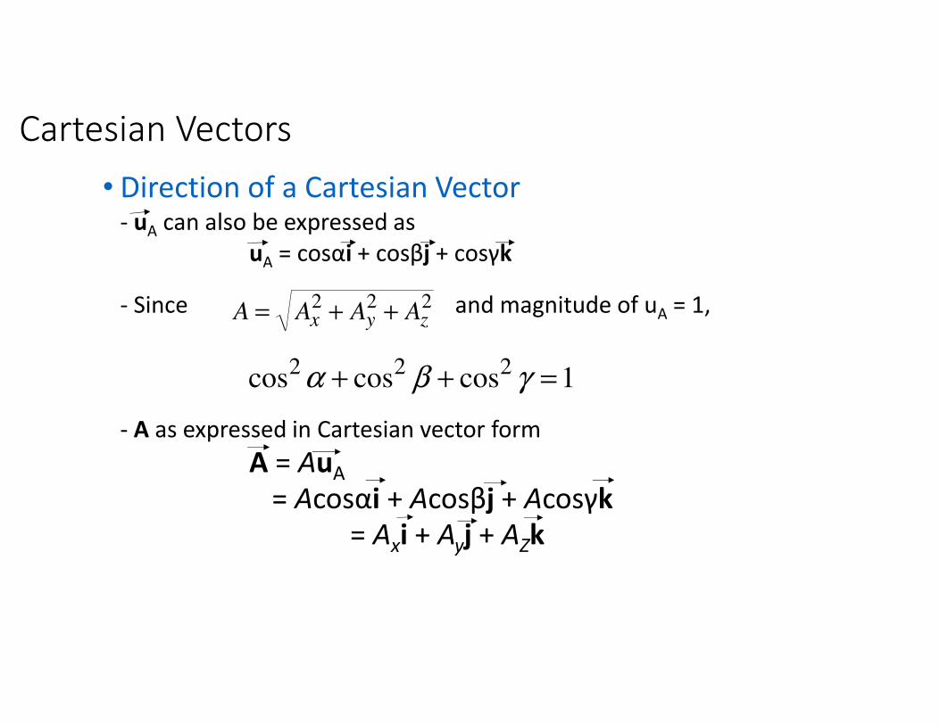
Cartesian Vectors
• Direction of a Cartesian Vector- uA can also be expressed as
uA = cosαi + cosβj + cosγk
- Since and magnitude of uA = 1,
- A as expressed in Cartesian vector form
A = AuA
= Acosαi + Acosβj + Acosγk
= Axi + Ayj + AZk
222
zyx AAAA ++=
1coscoscos222 =++ γβα
Addition Addition Addition Addition of a System of of a System of of a System of of a System of CoplanarCoplanarCoplanarCoplanar ForcesForcesForcesForces
• Coplanar Force ResultantsTo determine resultant of several coplanar forces:
- Resolve force into x and y components
- Addition of the respective components using scalar algebra
- Resultant force is found using the parallelogram law
Addition of a System of Coplanar Forces
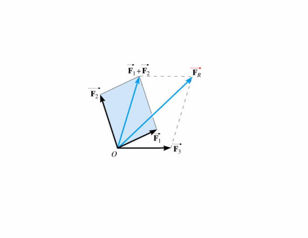
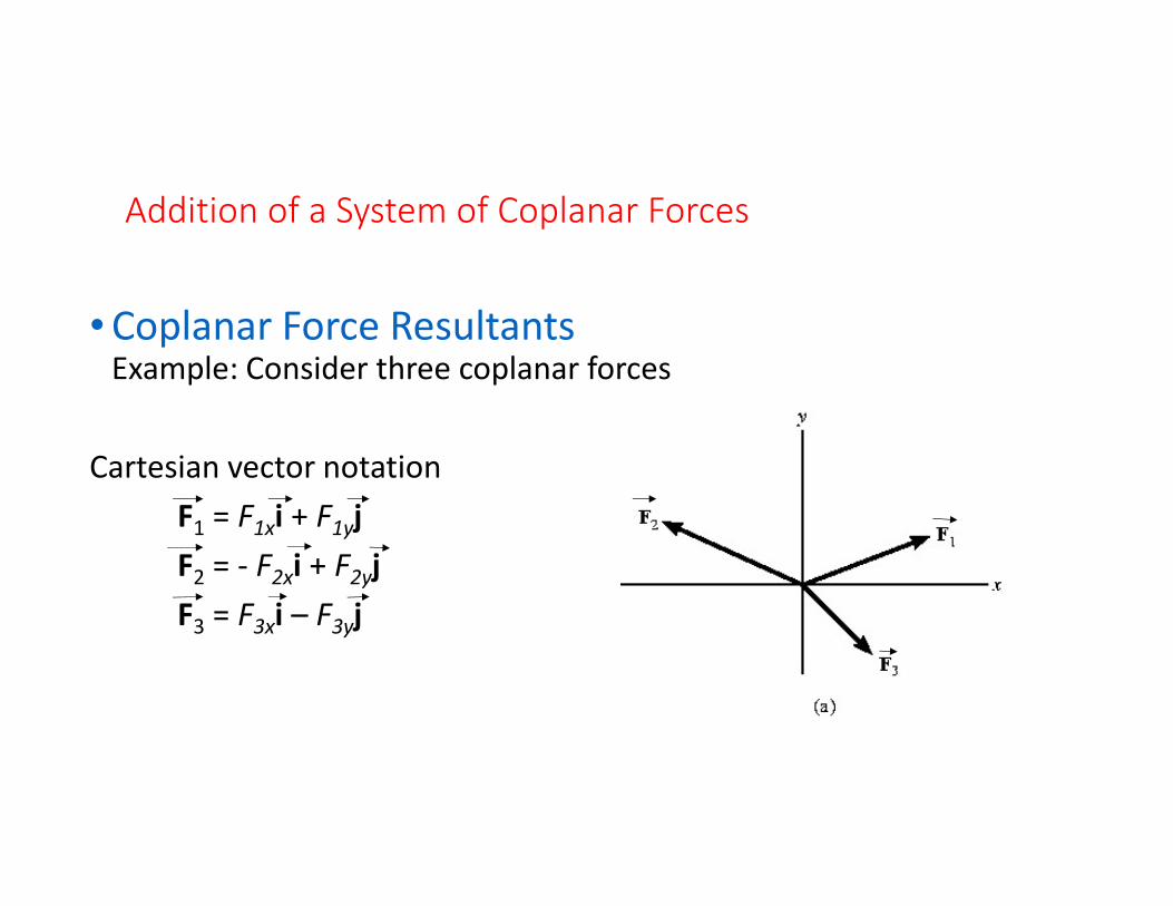
• Coplanar Force ResultantsExample: Consider three coplanar forces
Cartesian vector notation
F1 = F1xi + F1yj
F2 = - F2xi + F2yj
F3 = F3xi – F3yj
Addition of a System of Coplanar Forces
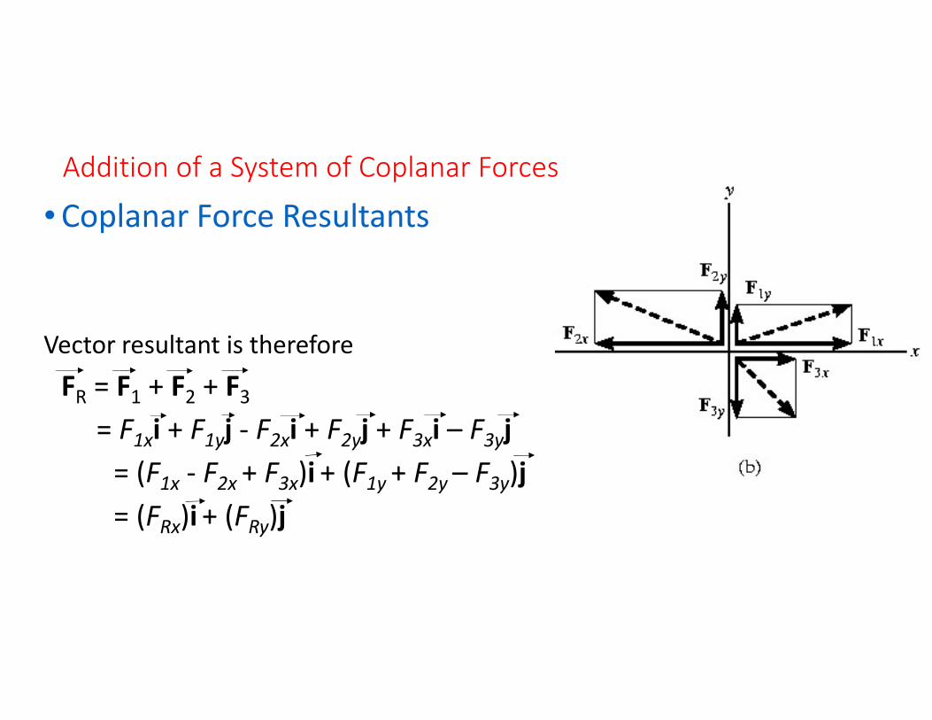
• Coplanar Force Resultants
Vector resultant is therefore
FR = F1 + F2 + F3
= F1xi + F1yj - F2xi + F2yj + F3xi – F3yj
= (F1x - F2x + F3x)i + (F1y + F2y – F3y)j
= (FRx)i + (FRy)j
Addition of a System of Coplanar Forces
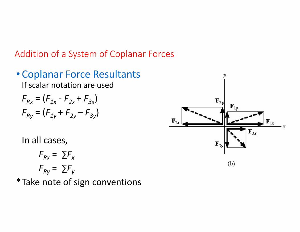
• Coplanar Force ResultantsIf scalar notation are used
FRx = (F1x - F2x + F3x)
FRy = (F1y + F2y – F3y)
In all cases,
FRx = ∑Fx
FRy = ∑Fy
*Take note of sign conventions

Addition of a System of Coplanar Forces
• Coplanar Force Resultants- Positive scalars = sense of direction along the positive coordinate axes
- Negative scalars = sense of direction along the negative coordinate axes
- Magnitude of FR can be found by Pythagorean Theorem
RyRxR FFF22 +=

Addition of a System of Coplanar Forces
• Coplanar Force Resultants- Direction angle θ (orientation of the force) can be found by trigonometry
Rx
Ry
F
F1
tan−=θ
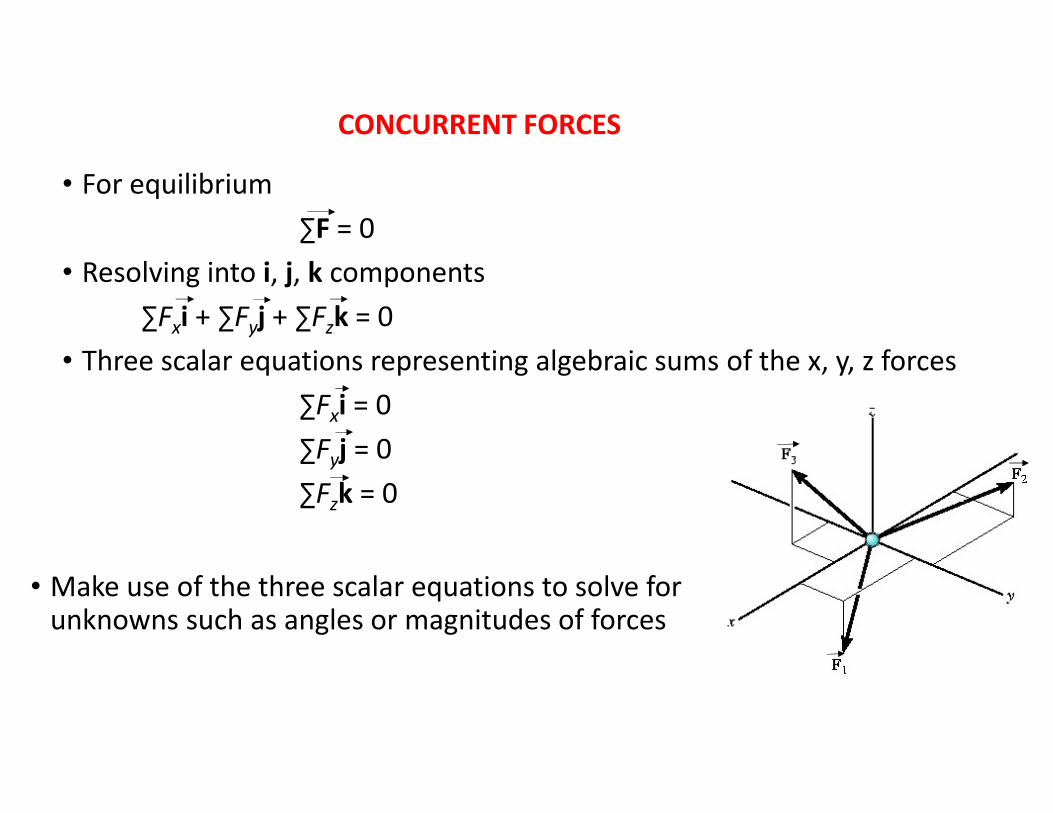
• For equilibrium
∑F = 0
• Resolving into i, j, k components
∑Fxi + ∑Fyj + ∑Fzk = 0
• Three scalar equations representing algebraic sums of the x, y, z forces
∑Fxi = 0
∑Fyj = 0
∑Fzk = 0
• Make use of the three scalar equations to solve for unknowns such as angles or magnitudes of forces
CONCURRENT FORCES
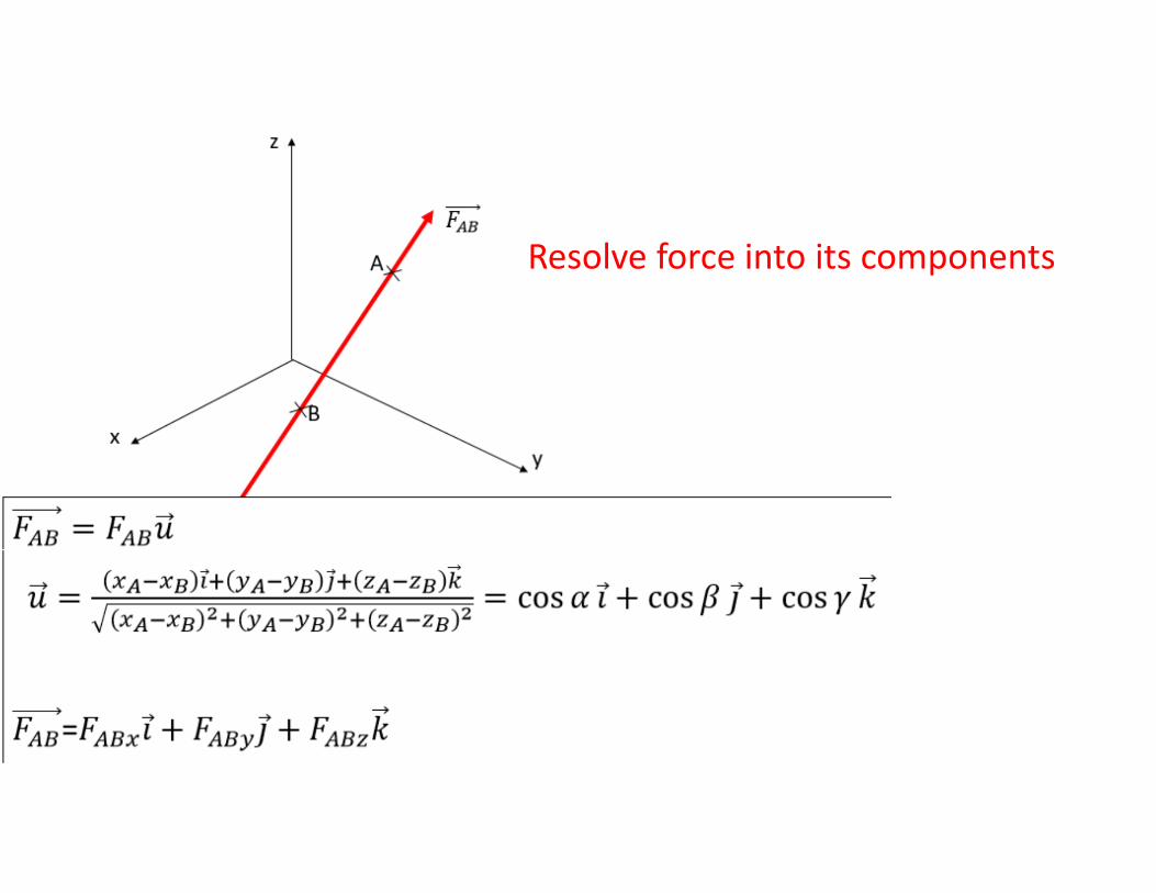
Resolve force into its components
q
�L
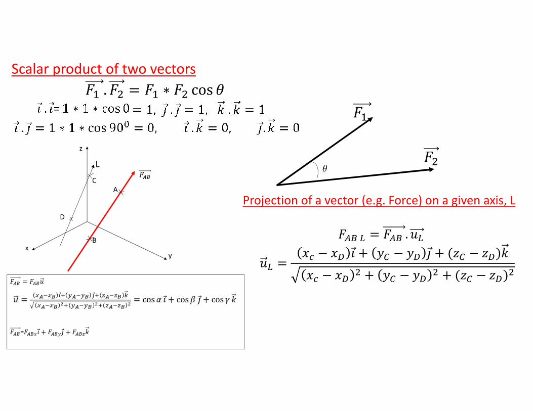
Projection of a vector (e.g. Force) on a given axis, L
� � � � . ��
�� ��� � �� �⃗ � �� � �� �⃗ � ��� � ����
�� � ��� � �� � ��
� � ��� � ����
C
D
Scalar product of two vectors
. � � ∗ � cos "
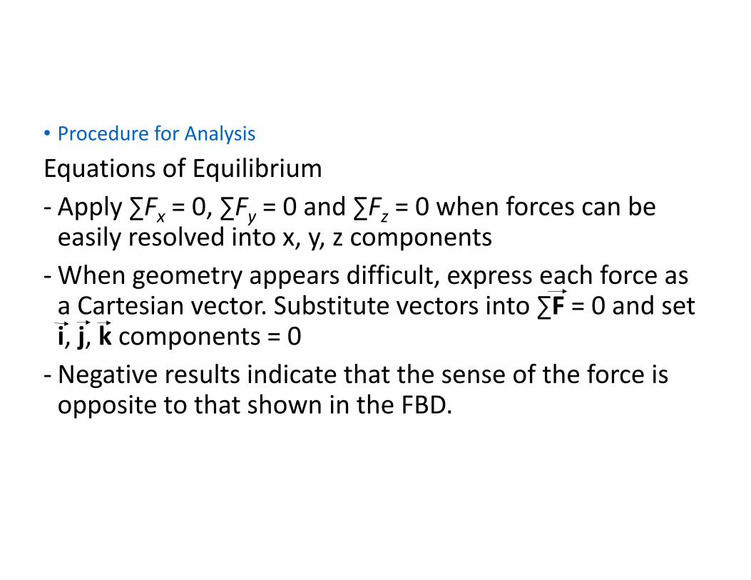
• Procedure for Analysis
Equations of Equilibrium
- Apply ∑Fx = 0, ∑Fy = 0 and ∑Fz = 0 when forces can be easily resolved into x, y, z components
- When geometry appears difficult, express each force as a Cartesian vector. Substitute vectors into ∑F = 0 and set i, j, k components = 0
- Negative results indicate that the sense of the force is opposite to that shown in the FBD.
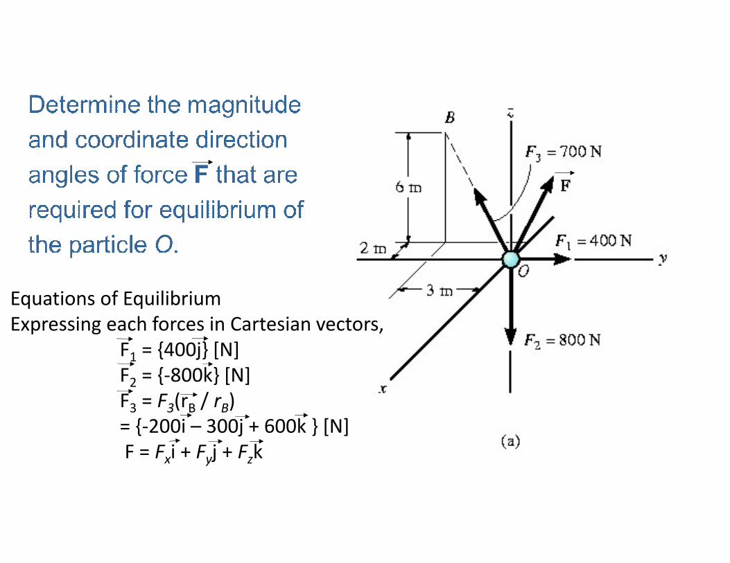
Equations of Equilibrium
Expressing each forces in Cartesian vectors,
F1 = {400j} [N]
F2 = {-800k} [N]
F3 = F3(rB / rB)
= {-200i – 300j + 600k } [N]
F = Fxi + Fyj + Fzk
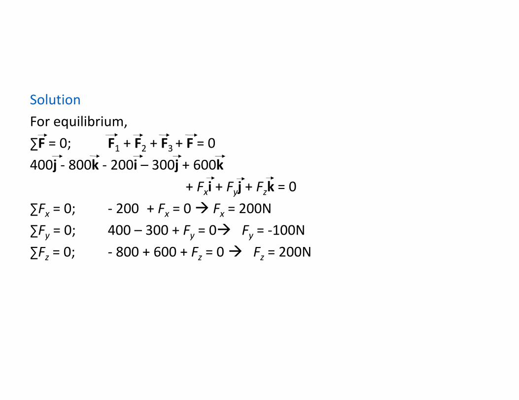
Solution
For equilibrium,
∑F = 0; F1 + F2 + F3 + F = 0
400j - 800k - 200i – 300j + 600k
+ Fxi + Fyj + Fzk = 0
∑Fx = 0; - 200 + Fx = 0 Fx = 200N
∑Fy = 0; 400 – 300 + Fy = 0 Fy = -100N
∑Fz = 0; - 800 + 600 + Fz = 0 Fz = 200N
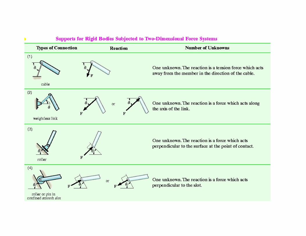
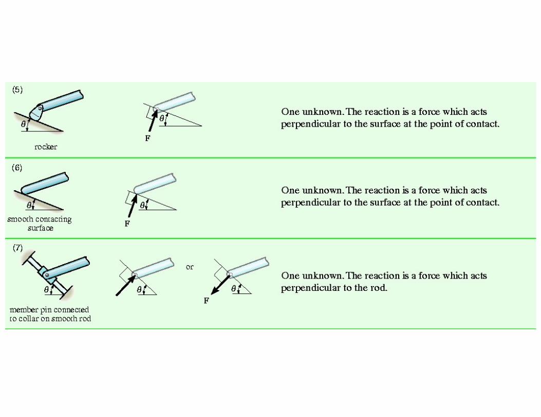
Procedure for Drawing a FBD(Free-Body Diagram)
1. Draw outlined shape
- Isolate object from its surroundings
2. Show all the forces
- Indicate all the forces
3. Identify each forces
- Known forces should be labeled with proper magnitude and direction
- Letters are used to represent magnitude and directions of unknown forces
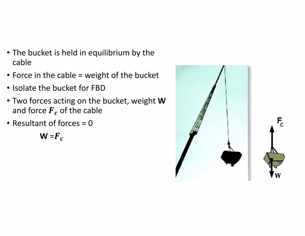
• The bucket is held in equilibrium by the cable
• Force in the cable = weight of the bucket
• Isolate the bucket for FBD
• Two forces acting on the bucket, weight Wand force #$ of the cable
• Resultant of forces = 0
W =#$
Weight and Center of Gravity
• When a body is subjected to gravity, each particle has a specified weight
• For entire body, consider gravitational forces as a system of parallel forces acting on all particles within the boundary
• The system can be represented by a single resultant force, known as weight W of the body
• Location of the force application is known as the center of gravity
*Center of gravity occurs at the geometric center or centroid for
uniform body of homogenous material
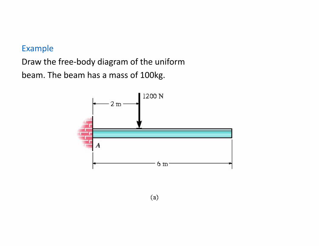
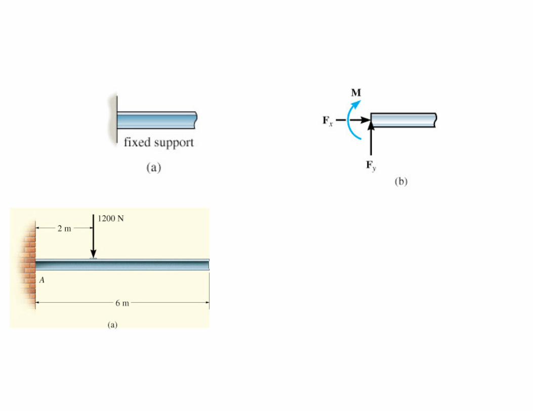
Example
Draw the free-body diagram of the uniform
beam. The beam has a mass of 100kg.
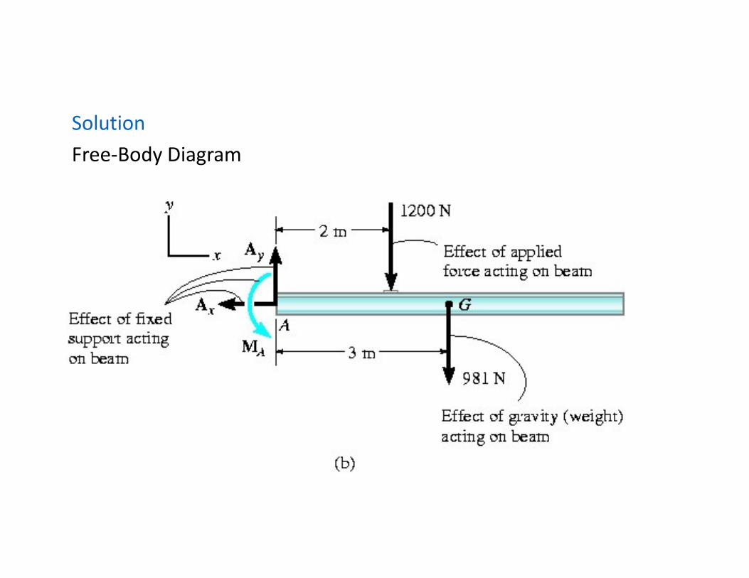
Solution
Free-Body Diagram
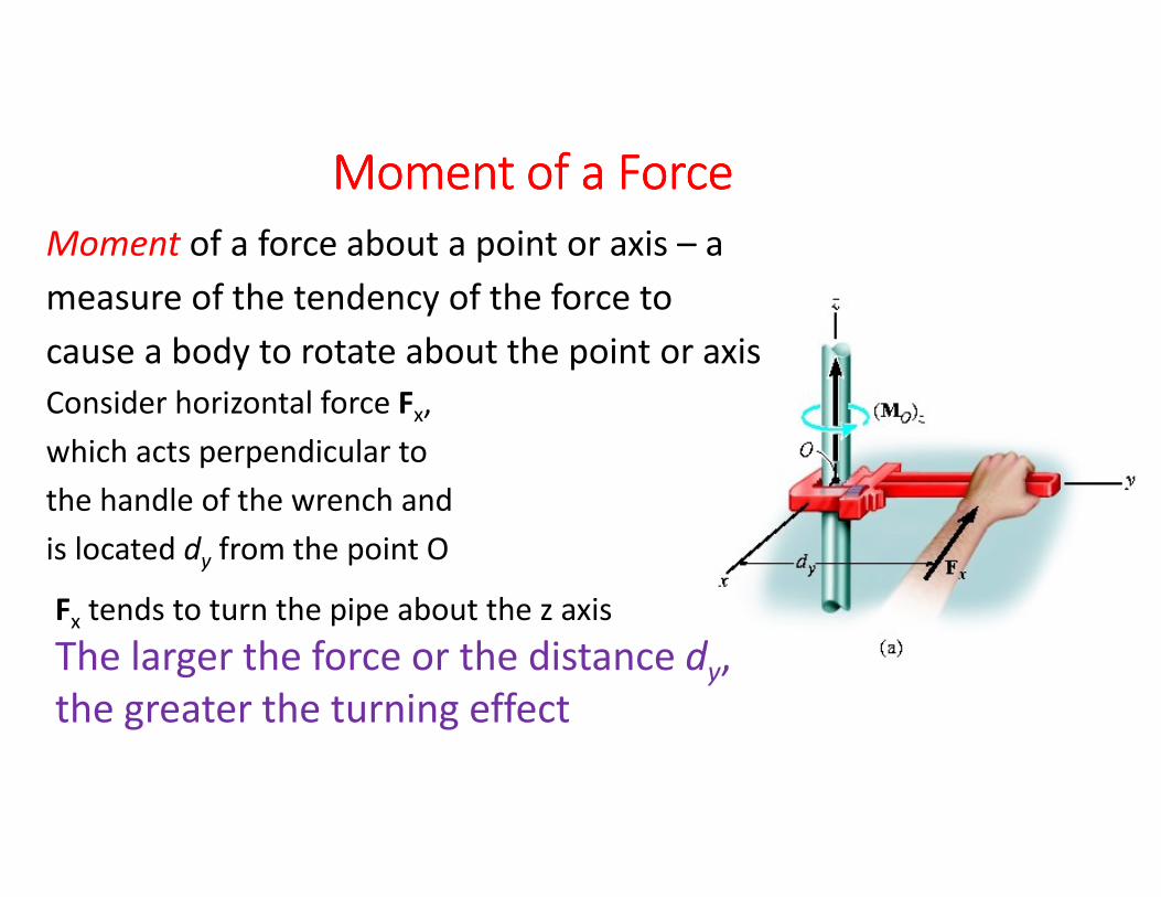
Moment of a ForceMoment of a ForceMoment of a ForceMoment of a Force
Moment of a force about a point or axis – a
measure of the tendency of the force to
cause a body to rotate about the point or axis
Consider horizontal force Fx,
which acts perpendicular to
the handle of the wrench and
is located dy from the point O
Fx tends to turn the pipe about the z axis
The larger the force or the distance dy,
the greater the turning effect
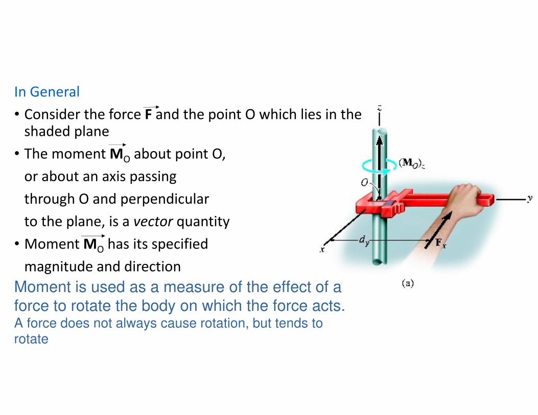
In General
• Consider the force F and the point O which lies in the shaded plane
• The moment MO about point O,
or about an axis passing
through O and perpendicular
to the plane, is a vector quantity
• Moment MO has its specified
magnitude and direction
Moment is used as a measure of the effect of a force to rotate the body on which the force acts.A force does not always cause rotation, but tends to rotate

MagnitudeFor magnitude of MO,
MO =% ∗ where d: moment arm or
perpendicular distance from the axis at point O to its line of action of the forceUnits for moment is [Nm]
Direction
• Direction of MO is specified by using “right hand rule”
- fingers of the right hand are curled to follow the sense of rotation when force rotates about point O, then open thumb. Thumb will be in the sense of moment vector

MO is shown by a vector arrow
with a curl to distinguish it from
force vector
Example (Fig b)
MO is represented by the
counterclockwise curl, which indicates
the action of F
• Moment vector is perpendicular to
the plane containing F and d
• Moment axis intersects
the plane at point O

Resultant Moment of a System of
Coplanar Forces
• Resultant moment, MRo = addition of the moments of all the forces algebraically since all moment forces are collinear
MRo = ∑(% ∗ ) taking counterclockwise to be positive

Moment of a Force – 2Dimensional case
Example Determine the resultant moment of the four
forces acting on the rod about point O
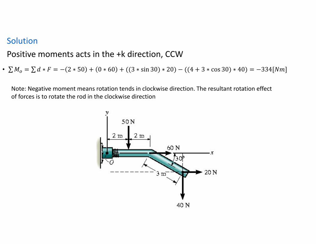
Solution
Positive moments acts in the +k direction, CCW
• ∑ '( = ∑ % ∗ = − 2 ∗ 50 + 0 ∗ 60 + ((3 ∗ sin 30) ∗ 20) − ((4 + 3 ∗ cos 30) ∗ 40) = −334[23]
Note: Negative moment means rotation tends in clockwise direction. The resultant rotation effect
of forces is to rotate the rod in the clockwise direction
VECTOR PRODUCT
or CROSS PRODUCT
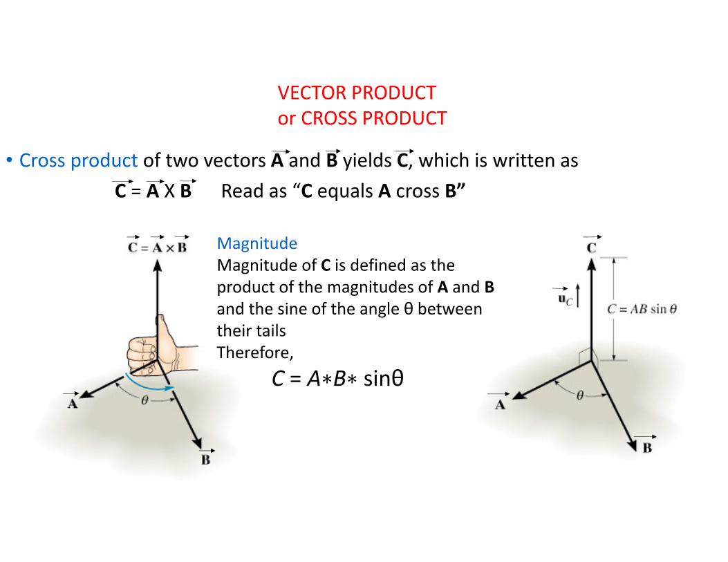
• Cross product of two vectors A and B yields C, which is written as
C = A X B Read as “C equals A cross B”
Magnitude
Magnitude of C is defined as the
product of the magnitudes of A and B
and the sine of the angle θ between
their tails
Therefore,
C = A∗B∗ sinθ
Cross Product
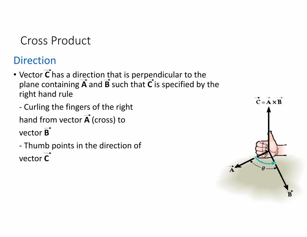
Direction
• Vector C has a direction that is perpendicular to the plane containing A and B such that C is specified by the right hand rule
- Curling the fingers of the right
hand from vector A (cross) to
vector B
- Thumb points in the direction of
vector C
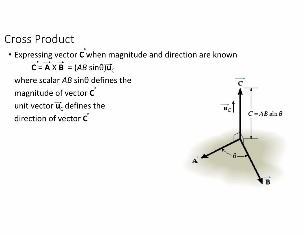
Cross Product
• Expressing vector C when magnitude and direction are known
C = A X B = (AB sinθ)uC
where scalar AB sinθ defines the
magnitude of vector C
unit vector uC defines the
direction of vector C
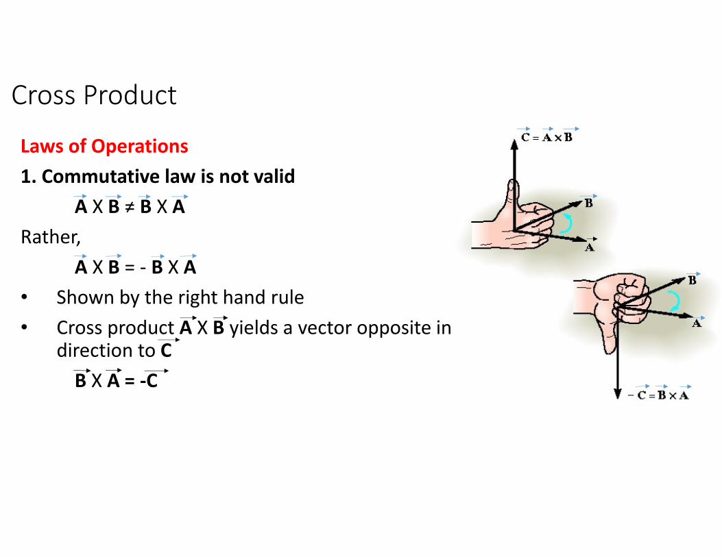
Cross Product
Laws of Operations
1. Commutative law is not valid
A X B ≠ B X A
Rather,
A X B = - B X A
• Shown by the right hand rule
• Cross product A X B yields a vector opposite in direction to C
B X A = -C

Cross Product
Laws of Operations
2. Multiplication by a Scalar
a( A X B ) = (aA) X B = A X (aB) = ( A X B )a
3. Distributive Law
A X ( B + D ) = ( A X B ) + ( A X D )
• Proper order of the cross product must be maintained since they are not commutative
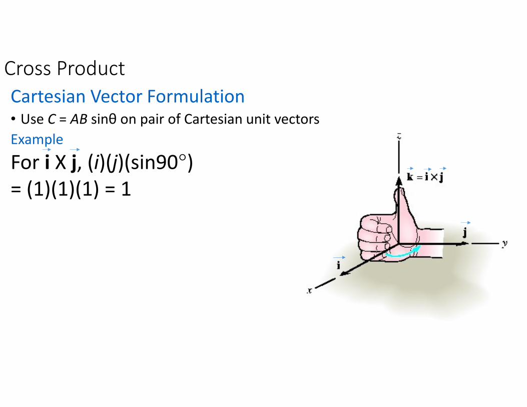
Cross Product
Cartesian Vector Formulation• Use C = AB sinθ on pair of Cartesian unit vectors
Example
For i X j, (i)(j)(sin90°)
= (1)(1)(1) = 1
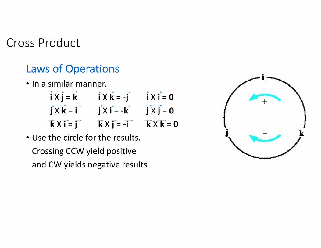
Cross Product
Laws of Operations
• In a similar manner,
i X j = k i X k = -j i X i = 0
j X k = i j X i = -k j X j = 0
k X i = j k X j = -i k X k = 0
• Use the circle for the results.
Crossing CCW yield positive
and CW yields negative results
Cross Product
Laws of Operations
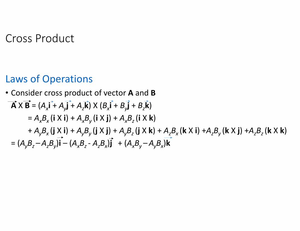
• Consider cross product of vector A and B
A X B = (Axi + Ayj + Azk) X (Bxi + Byj + Bzk)
= AxBx (i X i) + AxBy (i X j) + AxBz (i X k)
+ AyBx (j X i) + AyBy (j X j) + AyBz (j X k) + AzBx (k X i) +AzBy (k X j) +AzBz (k X k)
= (AyBz – AzBy)i – (AxBz - AzBx)j + (AxBy – AyBx)k
Cross Product
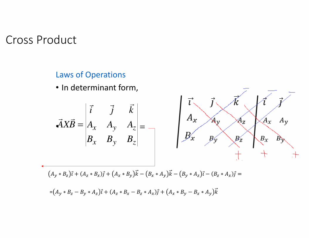
Laws of Operations
• In determinant form,
• =
zyx
zyx
BBB
AAA
kji
BXA
rrr
rr=
56 ∗ 78 �⃗ + 58 ∗ 79 �⃗ + 59 ∗ 76 � − 79 ∗ 56 � − 76 ∗ 58 �⃗ − 78 ∗ 59 �⃗ =
= 56 ∗ 78 − 76 ∗ 58 �⃗ + 58 ∗ 79 − 78 ∗ 59 �⃗ + 59 ∗ 76 − 79 ∗ 56 �
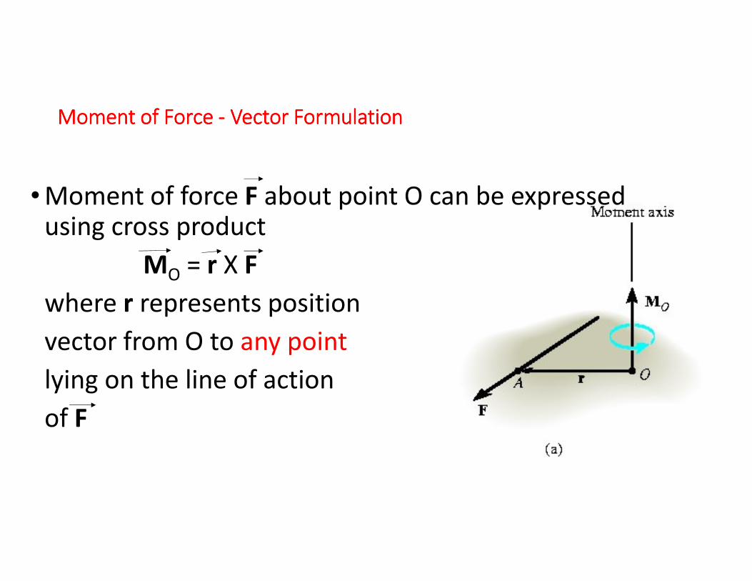
Moment Moment Moment Moment of Force of Force of Force of Force ---- Vector FormulationVector FormulationVector FormulationVector Formulation
• Moment of force F about point O can be expressed using cross product
MO = r X F
where r represents position
vector from O to any point
lying on the line of action
of F
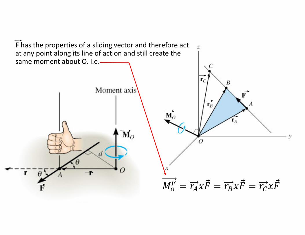
'(: = ;��⃗ = ; �⃗ = ;��⃗
F has the properties of a sliding vector and therefore act at any point along its line of action and still create the same moment about O. i.e.

Moment of Force - Vector Formulation
Magnitude
• For magnitude of cross product,
MO = rF sinθ
where θ is the angle measured between tails of r and F
• Treat r as a sliding vector. Since d = r sinθ,
MO = rF sinθ = F (rsinθ) = Fd
Moment of Force - Vector Formulation
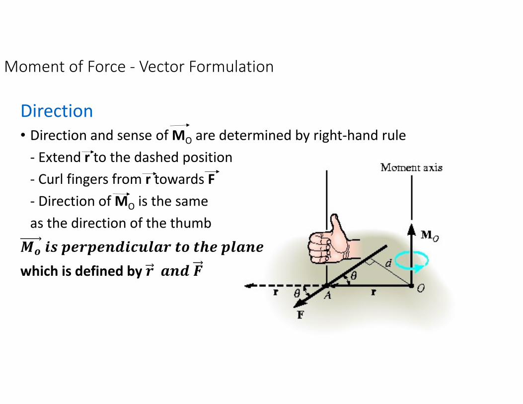
Direction
• Direction and sense of MO are determined by right-hand rule
- Extend r to the dashed position
- Curl fingers from r towards F
- Direction of MO is the same
as the direction of the thumb
<= >? @AB@ACD>$EFGB H= HIA @FGCA
which is defined by B GCD #
Moment of Force - Vector Formulation
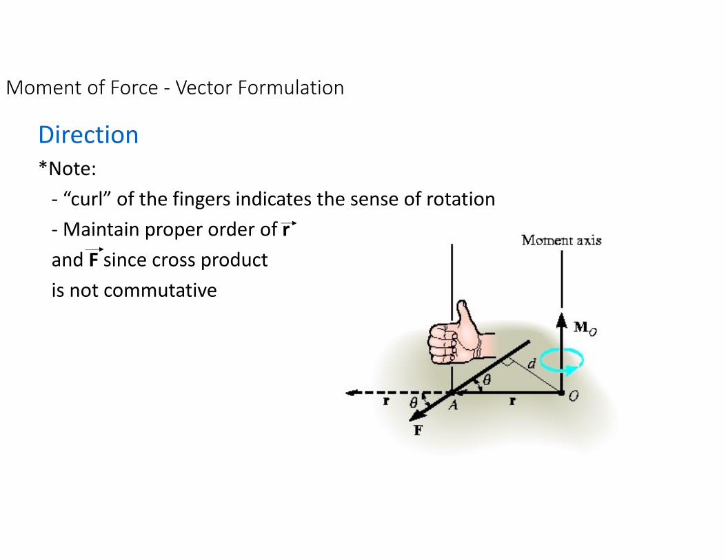
Direction
*Note:
- “curl” of the fingers indicates the sense of rotation
- Maintain proper order of r
and F since cross product
is not commutative
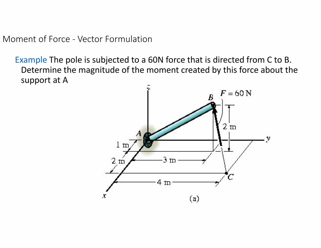
Moment of Force - Vector Formulation
Example The pole is subjected to a 60N force that is directed from C to B. Determine the magnitude of the moment created by this force about the support at A
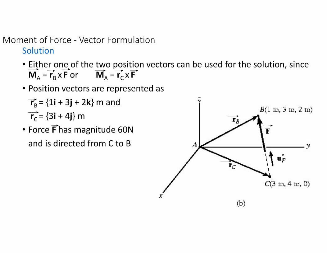
Moment of Force - Vector FormulationSolution
• Either one of the two position vectors can be used for the solution, since MA = rB x F or MA = rC x F
• Position vectors are represented as
rB = {1i + 3j + 2k} m and
rC = {3i + 4j} m
• Force F has magnitude 60N
and is directed from C to B

Moment of Force - Vector FormulationSolution
Substitute into determinant formulation
'� = 160�⃗ � 120�⃗ � 100� 23
'� � 160 � � 120 � � 100 � � 2241234
Direction angles of '�
cos � �160
224 , cos � �
�120
224 , cos � �
100
224
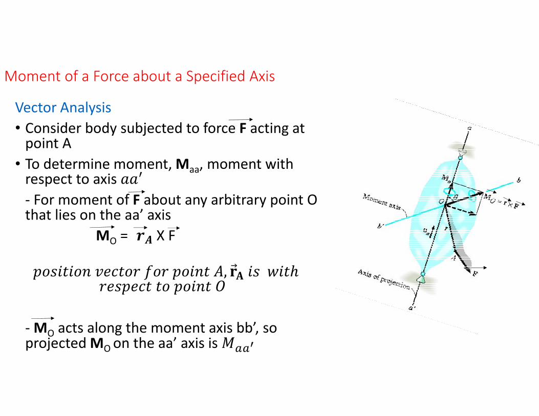
Moment of a Force about a Specified Axis
Vector Analysis
• Consider body subjected to force F acting at point A
• To determine moment, Maa, moment with respect to axis KKL
- For moment of F about any arbitrary point O that lies on the aa’ axis
MO = BM X F
NOPQRQOS TUVRO; WO; NOQSR 5, X⃗Y QP ZQRℎ ;UPNUVR RO NOQSR \
- MO acts along the moment axis bb’, so projected MO on the aa’ axis is ']]^
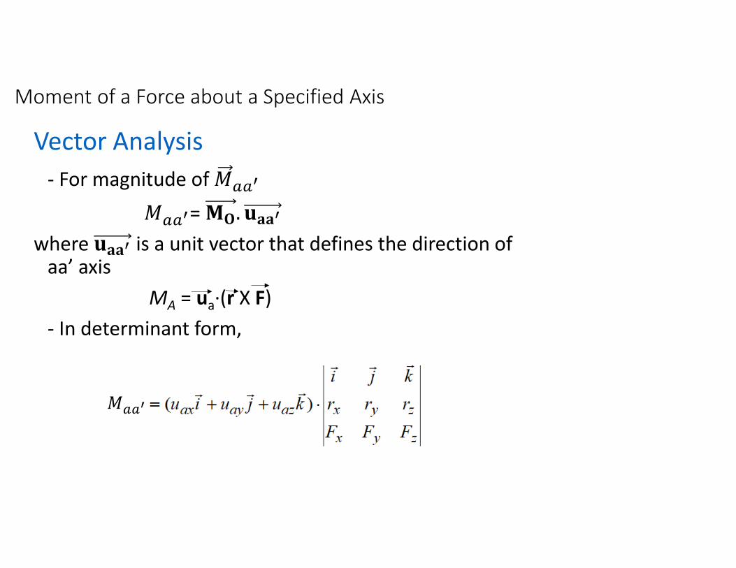
Moment of a Force about a Specified Axis
Vector Analysis
- For magnitude of ']]^
']]^= _`. abb^
where abb^ is a unit vector that defines the direction of aa’ axis
MA = ua·(r X F)
- In determinant form,
']]^
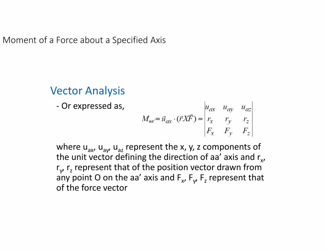
Moment of a Force about a Specified Axis
Vector Analysis
- Or expressed as,
where uax, uay, uaz represent the x, y, z components of the unit vector defining the direction of aa’ axis and rx, ry, rz represent that of the position vector drawn from any point O on the aa’ axis and Fx, Fy, Fz represent that of the force vector
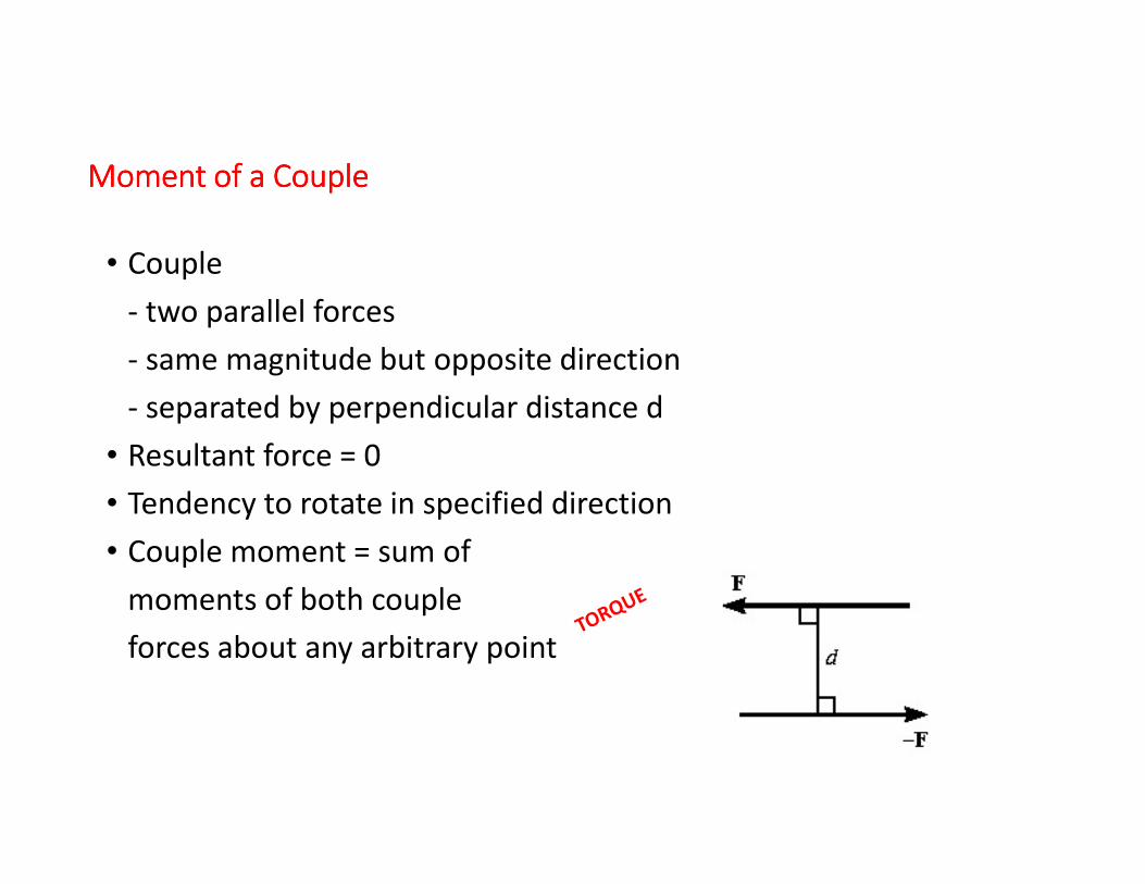
Moment Moment Moment Moment of a Coupleof a Coupleof a Coupleof a Couple
• Couple
- two parallel forces
- same magnitude but opposite direction
- separated by perpendicular distance d
• Resultant force = 0
• Tendency to rotate in specified direction
• Couple moment = sum of
moments of both couple
forces about any arbitrary point
Moment of a Couple
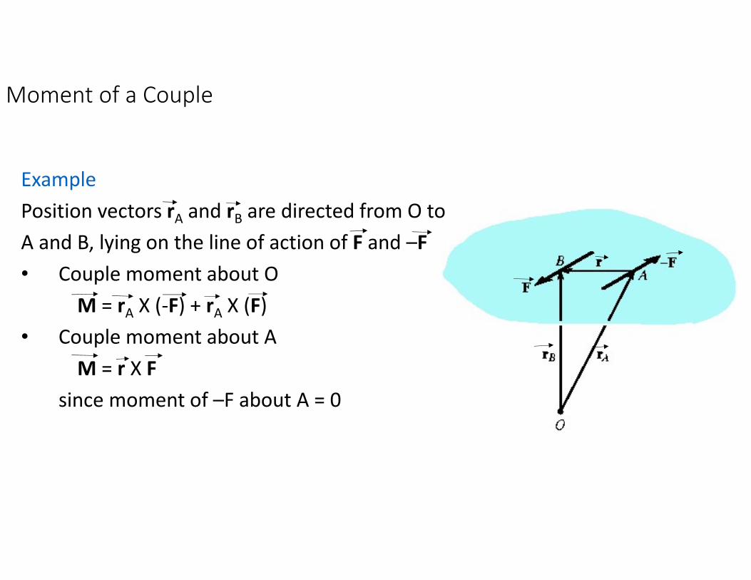
Example
Position vectors rA and rB are directed from O to
A and B, lying on the line of action of F and –F
• Couple moment about O
M = rA X (-F) + rA X (F)
• Couple moment about A
M = r X F
since moment of –F about A = 0
Moment of a Couple
• A couple moment is a free vector
- It can act at any point since M depends only on the position vector rdirected between forces and not position vectors rA and rB, directed from O to the forces
- Unlike moment of force, it do not require a definite point or axis
Moment of a Couple
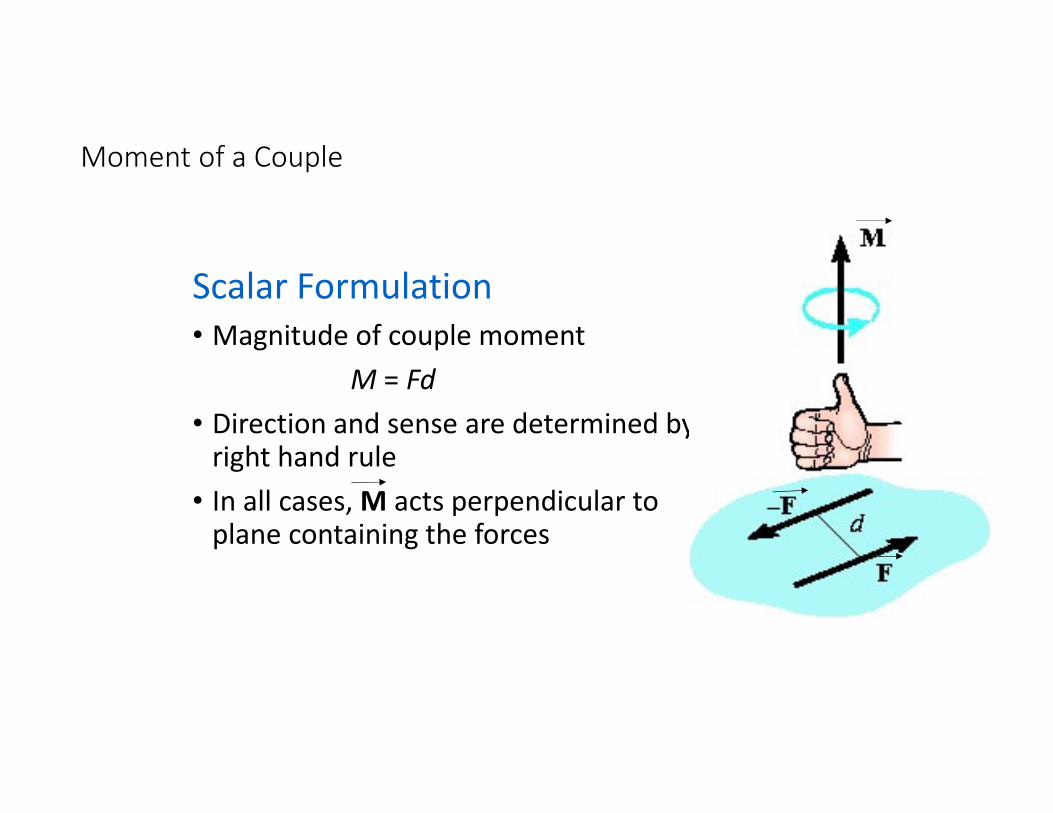
Scalar Formulation
• Magnitude of couple moment
M = Fd
• Direction and sense are determined by right hand rule
• In all cases, M acts perpendicular to plane containing the forces
Moment of a Couple
Equivalent Couples
• Two couples are equivalent if they produce the same moment
• Since moment produced by the couple is always perpendicular to the plane containing the forces, forces of equal couples either lie on the same plane or plane parallel to one another