ford bolted flex couplings
TRANSCRIPT

Section M 06/2017
Web Revision 12/15/2017
DQS Inc.
THE FORD METER BOX COMPANY, INC.CERTIFIED TO ISO 9001:2015
10004466
FordCast Couplingsand Adapters
M-2
Contents Page Coupling Numbering System . . . . . . . . . . . . . . . . . . . . . . . . . . . . . . . . . . . . . . . . . . 3 Features of Ford Cast Couplings, Style FC1 and FC2A . . . . . . . . . . . . . . . . . . . . . 4 Ford Couplings, Style FC1 . . . . . . . . . . . . . . . . . . . . . . . . . . . . . . . . . . . . . . . . . . . 5 Ford Extended Length Ductile Iron Couplings, Style FC1-L12 . . . . . . . . . . . . . . . . 6 Ford Transition Couplings, Style FC2A . . . . . . . . . . . . . . . . . . . . . . . . . . . . . . . . . . 7 Transition Coupling Parts . . . . . . . . . . . . . . . . . . . . . . . . . . . . . . . . . . . . . . . . . . . . 8 Ford Extended Length Transition Couplings, Style FC2A-L12 . . . . . . . . . . . . . . . . 9 Extended Length Transition Coupling Parts . . . . . . . . . . . . . . . . . . . . . . . . . . . . . 10 Ford Ultra-Flex Wide Range Couplings, Style FC2W . . . . . . . . . . . . . . . . . . 11 - 12 Ford Ultra-Flex Wide Range Long Sleeve Couplings, Style FC2W-L12 . . . . . . . . 12 Ford Reducing Couplings, Style FRC . . . . . . . . . . . . . . . . . . . . . . . . . . . . . . . . . . 13 Ford Insulating Boots, Style FIB . . . . . . . . . . . . . . . . . . . . . . . . . . . . . . . . . . . . . . 13 Ford Flanged Coupling Adapters, Style FFCA . . . . . . . . . . . . . . . . . . . . . . . . . . . 14 Ford Cut-In Couplings, Style FRR . . . . . . . . . . . . . . . . . . . . . . . . . . . . . . . . . . . . . 15 Ford End Cap Couplings, Style FEC and FC2W-EC . . . . . . . . . . . . . . . . . . . . . . 16 Ford Mechanical Joint Flange Adapter, Style MJFA . . . . . . . . . . . . . . . . . . . 17 - 18 Ford Mechanical Joint Coupling, Style MJC . . . . . . . . . . . . . . . . . . . . . . . . . 19 - 20 Ford FC2W Ultra-Flex Installation Instructions . . . . . . . . . . . . . . . . . . . . . . . . . . . 21 Installation Instructions for Ford Flexible Couplings . . . . . . . . . . . . . . . . . . . . . . . 21 Stainless Steel Inserts for HDPE Pipe . . . . . . . . . . . . . . . . . . . . . . . . . . . . . . . . . 22 Pipe O .D . Chart . . . . . . . . . . . . . . . . . . . . . . . . . . . . . . . . . . . . . . . . . . . . . . . . . . . 23 Warranty . . . . . . . . . . . . . . . . . . . . . . . . . . . . . . . . . . . . . . . . . . . . . . . . . . . . . . . . 24
The Ford Meter Box Company, Inc . manufacturing facilities are at the following locations:
Main Office – The Ford Meter Box Company, Inc .775 Manchester AvenueP .O . Box 443Wabash, Indiana 46992-0443Phone: 260-563-3171 Fax: 800-826-3487
Pipe Products Division – The Ford Meter Box Company, Inc .815 Miles ParkwayPell City, Alabama 35125Phone: 205-884-4480 Fax: 205-884-4484

M-3
F C 2 A - 6 6 3 - 7 2 0 - S H
TYPE OF COUPLING FC1 = Cast Coupling FC2A = Cast Transition Coupling FIB = Insulating Boot FRC = Reducing Coupling FFCA = Flanged Coupling Adapter FRR = Cut-In Coupling FEC = End Cap Coupling
OD SIZEUse listed catalog sizes .
For most coupling types each number indicates top end of range .Only the FC1 and FC2A have an OD size for each coupling end .
OPTIONAL FEATURES SH = Type 304 Stainless Steel Nuts and Bolts ESH = Type 304 Stainless Steel Nuts and Bolts with Epoxy Coated Coupling N = NBR (Buna-N) Gaskets EPDM = EPDM Gaskets BBN = Blue Fluorocarbon Coated Nuts and Bolts L12 = 12" Long Center Sleeve Length (for FC1 4" and 6" FC2A - 4" - 12")
FOR FFCA COUPLING ADAPTERS AS2 = Two Anchor Studs AS4 = Four Anchor Studs (316 stainless steel nuts and bolts
available - contact factory)
See item listings in catalog section to ensure that desired sizes and options are available .
Ford Cast Coupling Numbering System
one end other end
F C 2 W - 6 - S H
TYPE OF COUPLING FC2W = Ductile Iron Wide Range Coupling (epoxy coated, NBR (Buna-N) gaskets)
NOMINAL PIPE SIZE 3 = 3" 4 = 4" 6 = 6" 8 = 8" 10 = 10" 12 = 12" 16 = 16"
OPTIONAL FEATURES SH = Type 304 Stainless Steel Nuts and Bolts L12 = 12" Long Center Sleeve (sizes 3" - 12") EPDM = EPDM Gasket EC = End Cap with 2" FIP Threaded Boss (sizes 4"-12") BBN = Blue Fluorocarbon Coated Nuts and Bolts
(316 stainless steel nuts and boltsavailable - contact factory)
Ford offers many products that are classified to ANSI/NSF Standard 61 . To verify if a product is classified to ANSI/NSF Standard 61, contact the Ford Meter Box Customer Service Department at 260-563-3171 or visit fordmeterbox .com . Ford Meter Box meets your need for ANSI/NSF Standard 61 approved items with products that are proven and reliable .
TYPE OF COUPLING
M J F A - 6 - I 3-I = 3" 4-I = 4" 6-I = 6" 8-I = 8" 10-I = 10" 12-I = 12"NOMINAL PIPE SIZE
MJFA = Mechanical Joint Flange Adapter MJC = Mechanical Joint Couplings
M-4
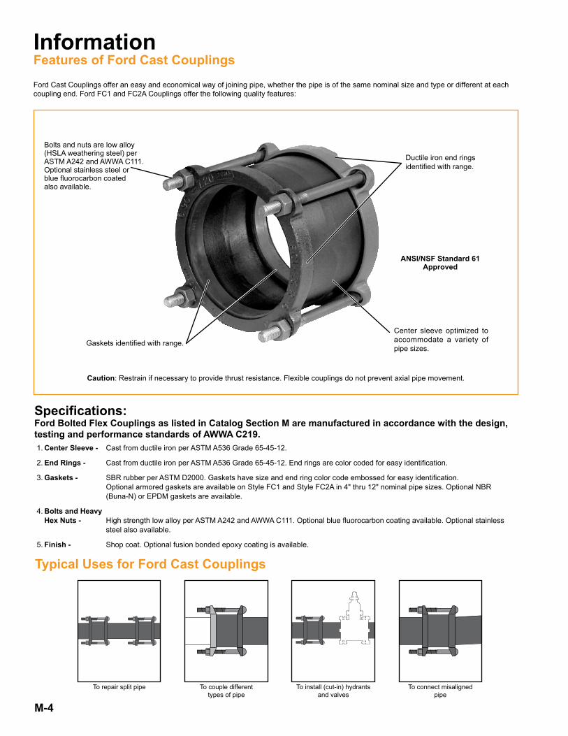
Bolts and nuts are low alloy (HSLA weathering steel) per ASTM A242 and AWWA C111 .Optional stainless steel orblue fluorocarbon coatedalso available .
Center sleeve optimized to accommodate a variety of pipe sizes .
Ductile iron end rings identified with range .
Gaskets identified with range .
To connect misalignedpipe
To install (cut-in) hydrantsand valves
To couple differenttypes of pipe
To repair split pipe
Specifications:Ford Bolted Flex Couplings as listed in Catalog Section M are manufactured in accordance with the design, testing and performance standards of AWWA C219. 1 . Center Sleeve - Cast from ductile iron per ASTM A536 Grade 65-45-12 .
2 . End Rings - Cast from ductile iron per ASTM A536 Grade 65-45-12 . End rings are color coded for easy identification .
3 . Gaskets - SBR rubber per ASTM D2000 . Gaskets have size and end ring color code embossed for easy identification . Optional armored gaskets are available on Style FC1 and Style FC2A in 4" thru 12" nominal pipe sizes . Optional NBR (Buna-N) or EPDM gaskets are available .
4 . Bolts and Heavy Hex Nuts - High strength low alloy per ASTM A242 and AWWA C111 . Optional blue fluorocarbon coating available . Optional stainless steel also available . 5 . Finish - Shop coat . Optional fusion bonded epoxy coating is available .
InformationFeatures of Ford Cast Couplings
Ford Cast Couplings offer an easy and economical way of joining pipe, whether the pipe is of the same nominal size and type or different at each coupling end . Ford FC1 and FC2A Couplings offer the following quality features:
Typical Uses for Ford Cast Couplings
Caution: Restrain if necessary to provide thrust resistance . Flexible couplings do not prevent axial pipe movement .
ANSI/NSF Standard 61Approved

M-5
Style FC1 for Cast, Ductile Iron or PVC PipeNom.<br/>
PiPe<br/>
Size
Catalog<br/>
Number<br/>
Prefix
gaSket raNge eNd riNg<br/>
Color<br/>
Codeby
gaSket raNge eNd riNg<br/>
Color<br/>
Code
CeNter<br/>
Sleeve<br/>
leNgth
Number<br/>
of<br/>
boltS
aPProx.<br/>
Weight<br/>
lbS1St.<br/>half<br/>
Cat. No.2Nd half<br/>
Cat. No.2" FC1- 2 .34 — 2.63 Red 2 .34 — 2.63 Red 4" 2 6
2 1/2" FC1- See 2" FC2A on page M-7
4" FC1-4 .00 — 4.00 Red 4 .00 — 4.00 Red
5" 3 144 .50 — 4.80 Red 4 .50 — 4.80 Red4 .80 — 5.10 Black 4 .80 — 5.10 Black
6" FC1-6 .00 — 6.00 Red 6 .00 — 6.00 Red
5" 4 206 .30 — 6.30 Red 6 .30 — 6.30 Red6 .63 — 6.90 Red 6 .63 — 6.90 Red6 .90 — 7.20 Black 6 .90 — 7.20 Black
8" FC1-8 .00 — 8.00 Red 8 .00 — 8.00 Red
5" 5 298 .16 — 8.40 Red 8 .16 — 8.40 Red8 .63 — 9.05 Red 8 .63 — 9.05 Red9 .05 — 9.40 Black 9 .05 — 9.40 Black
10" FC1-10 .20 — 10.50 Red 10 .20 — 10.50 Red
6" 6 41 .510 .75 — 10.75 Red 10 .75 — 10.75 Red11 .10 — 11.46 Black 11 .10 — 11.46 Black
12" FC1-12 .24 — 12.50 Red 12 .24 — 12.50 Red
6" 7 54 .512 .75 — 12.75 Red 12 .75 — 12.75 Red13 .20 — 13.56 Black 13 .20 — 13.56 Black
Ford CouplingsStyle FC1
Suggested uses for Ford FC1 Couplings include water main repair, joining of plain end pipe, valve and hydrant installation, and flexible joint installation at critical areas of water main stress .The FC1 Couplings are constructed entirely of ductile iron components, permitting a strong, durable connection .Only the FC1 offers one gasket and end ring that fits all PVC and ductile iron pipe in the most popular sizes: 4", 6", and 8". Gasket ranges are embossed on each gasket for easy identification .
Style FC1 for Cast, Steel, Ductile Iron or PVC Pipe
Rated Working Pressure: Up to 300 psi
Component Parts for Style FC1 CouplingsNom.<br/>
PiPe<br/>
Size
gaSket<br/>
Cat. No.eNd riNg<br/>
Cat. No.CeNter Sleeve<br/>
Cat. No.bolt aNd Nut<br/>
Cat. No.
2" FC1G-234-263 FC1-RER-2 FC1-CS-2 FBN-58-65
4"FC1G-400 FC1-RER-4
FC1-CS-4 FBN-58-8FC1G-450-480 FC1-RER-4FC1G-480-510 FC1-BER-4
6"
FC1G-600 FC1-RER-6FC1-CS-6 FBN-58-8FC1G-630 FC1-RER-6
FC1G-663-690 FC1-RER-6FC1G-690-720 FC1-BER-6
8"
FC1G-800 FC1-RER-8FC1-CS-8 FBN-58-8FC1G-816-840 FC1-RER-8
FC1G-863-905 FC1-RER-8FC1G-905-940 FC1-BER-8
10"FC1G-1020-1050 FC1-RER-10
FC1-CS-10 FBN-58-9FC1G-1075 FC1-RER-10FC1G-1110-1146 FC1-BER-10
12"FC1G-1224-1250 FC1-RER-12
FC1-CS-12 FBN-58-9FC1G-1275 FC1-RER-12FC1G-1320-1356 FC1-BER-12
To order: Locate the gasket range that accommodates your pipe O .D . for both pipe ends . Use the top range of each gasket size to determine the part number . For example, to connect pipe with an O .D . of 6 .63 to a pipe with an O .D . of 7 .10, the catalog number is FC1-690-720 .Options: SH Standard coated coupling with Type 304 stainless steel nuts and bolts . Add “-SH” to the catalog number . ESH Epoxy coated coupling with Type 304 stainless steel nuts and bolts . Add “-ESH” to the catalog number . Q Standard coated coupling with Type 316 stainless steel nuts and bolts . Add “-Q” to the catalog number . Z Epoxy coated couplings with Type 316 stainless steel nuts and bolts . Add “-Z” to the catalog number . BBN Blue fluorocarbon coating on HSLA nuts and bolts . Add “-BBN” to catalog number . N NBR (Buna-N) gasket, standard coated coupling and standard alloy bolts . Add “-N” to the catalog number . EPDM EPDM gasket . Add “-EPDM” to the catalog number .
Example: FC1-690-720-ESH is an FC1 coupling with epoxy coating and stainless steel nuts and bolts .
Caution: Restrain if necessary to provide thrust resistance . Flexible couplings do not prevent axial pipe movement .
M-6
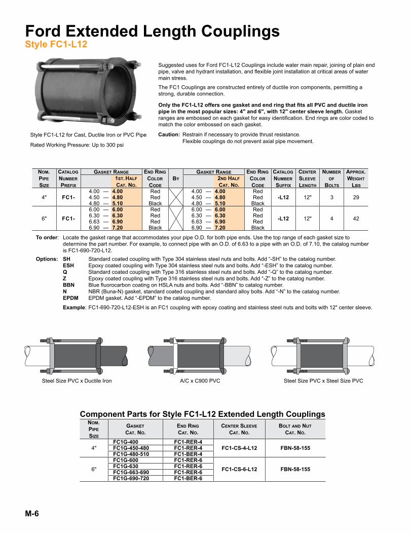
Style FC1-L12 for Cast, Ductile Iron or PVC Pipe
Rated Working Pressure: Up to 300 psi
Ford Extended Length CouplingsStyle FC1-L12
Suggested uses for Ford FC1-L12 Couplings include water main repair, joining of plain end pipe, valve and hydrant installation, and flexible joint installation at critical areas of water main stress .
The FC1 Couplings are constructed entirely of ductile iron components, permitting a strong, durable connection .
Only the FC1-L12 offers one gasket and end ring that fits all PVC and ductile iron pipe in the most popular sizes: 4" and 6", with 12" center sleeve length. Gasket ranges are embossed on each gasket for easy identification . End rings are color coded to match the color embossed on each gasket .
To order: Locate the gasket range that accommodates your pipe O .D . for both pipe ends . Use the top range of each gasket size to determine the part number . For example, to connect pipe with an O .D . of 6 .63 to a pipe with an O .D . of 7 .10, the catalog number is FC1-690-720-L12 .Options: SH Standard coated coupling with Type 304 stainless steel nuts and bolts . Add “-SH” to the catalog number . ESH Epoxy coated coupling with Type 304 stainless steel nuts and bolts . Add “-ESH” to the catalog number . Q Standard coated coupling with Type 316 stainless steel nuts and bolts . Add “-Q” to the catalog number . Z Epoxy coated coupling with Type 316 stainless steel nuts and bolts . Add “-Z” to the catalog number . BBN Blue fluorocarbon coating on HSLA nuts and bolts . Add “-BBN” to catalog number . N NBR (Buna-N) gasket, standard coated coupling and standard alloy bolts . Add “-N” to the catalog number . EPDM EPDM gasket . Add “-EPDM” to the catalog number .
Example: FC1-690-720-L12-ESH is an FC1 coupling with epoxy coating and stainless steel nuts and bolts with 12" center sleeve .
Style FC1 for Cast, Ductile Iron or PVC PipeNom.<br/>
PiPe<br/>
Size
Catalog<br/>
Number<br/>
Prefix
gaSket raNge eNd riNg<br/>
Color<br/>
Codeby
gaSket raNge eNd riNg<br/>
Color<br/>
Code
Catalog<br/>
Number<br/>
Suffix
CeNter<br/>
Sleeve<br/>
leNgth
Number<br/>
of<br/>
boltS
aPProx.<br/>
Weight<br/>
lbS1St.<br/>half<br/>
Cat. No.2Nd half<br/>
Cat. No.
4" FC1-4 .00 — 4.00 Red 4 .00 — 4.00 Red
12" 3 294 .50 — 4.80 Red 4 .50 — 4.80 Red -L124 .80 — 5.10 Black 4 .80 — 5.10 Black
6" FC1-6 .00 — 6.00 Red 6 .00 — 6.00 Red
-L12 12" 4 426 .30 — 6.30 Red 6 .30 — 6.30 Red6 .63 — 6.90 Red 6 .63 — 6.90 Red6 .90 — 7.20 Black 6 .90 — 7.20 Black
Component Parts for Style FC1-L12 Extended Length CouplingsNom.<br/>
PiPe<br/>
Size
gaSket<br/>
Cat. No.eNd riNg<br/>
Cat. No.CeNter Sleeve<br/>
Cat. No.bolt aNd Nut<br/>
Cat. No.
4"FC1G-400 FC1-RER-4
FC1-CS-4-L12 FBN-58-155FC1G-450-480 FC1-RER-4FC1G-480-510 FC1-BER-4
6"
FC1G-600 FC1-RER-6FC1-CS-6-L12 FBN-58-155FC1G-630 FC1-RER-6
FC1G-663-690 FC1-RER-6FC1G-690-720 FC1-BER-6
Steel Size PVC x Ductile Iron A/C x C900 PVC Steel Size PVC x Steel Size PVC
Caution: Restrain if necessary to provide thrust resistance . Flexible couplings do not prevent axial pipe movement .
M-7
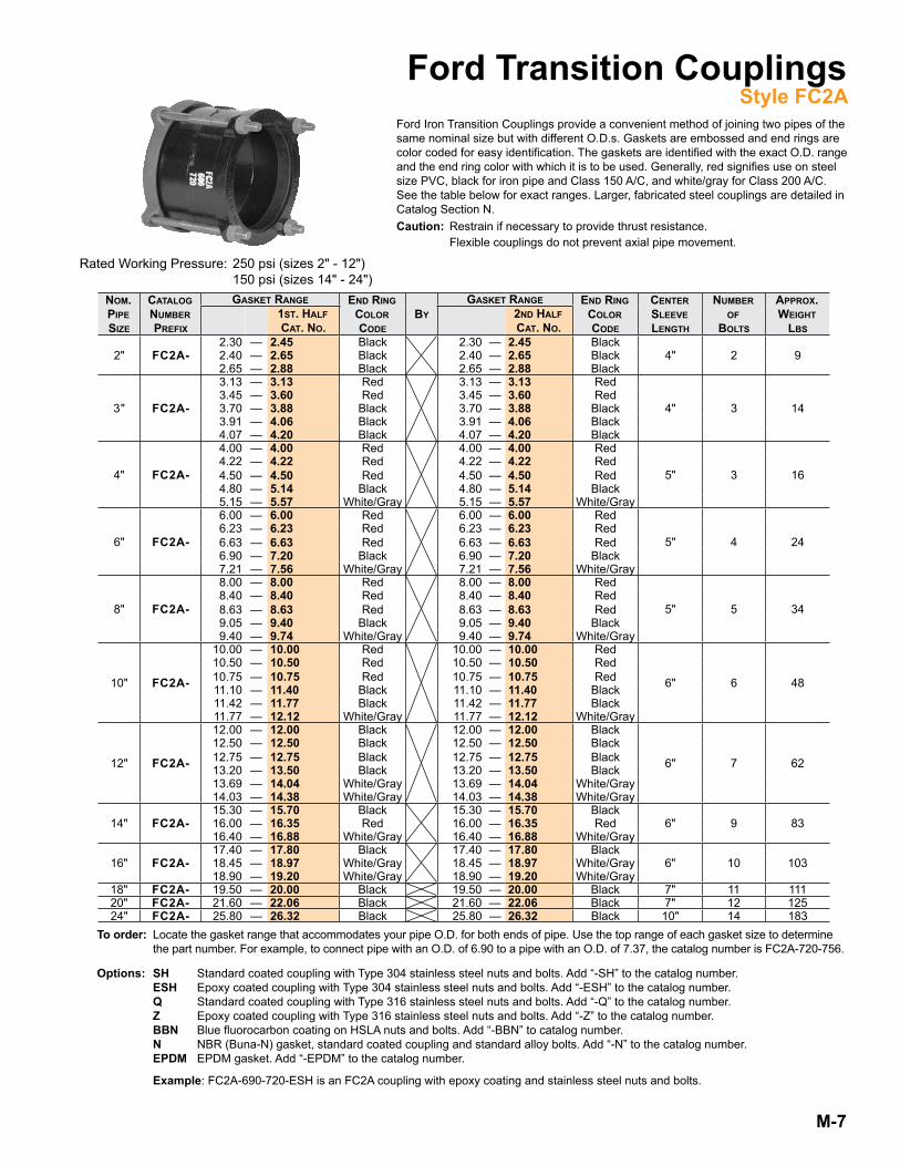
To order: Locate the gasket range that accommodates your pipe O .D . for both ends of pipe . Use the top range of each gasket size to determine the part number . For example, to connect pipe with an O .D . of 6 .90 to a pipe with an O .D . of 7 .37, the catalog number is FC2A-720-756 .
Options: SH Standard coated coupling with Type 304 stainless steel nuts and bolts . Add “-SH” to the catalog number . ESH Epoxy coated coupling with Type 304 stainless steel nuts and bolts . Add “-ESH” to the catalog number . Q Standard coated coupling with Type 316 stainless steel nuts and bolts . Add “-Q” to the catalog number . Z Epoxy coated coupling with Type 316 stainless steel nuts and bolts . Add “-Z” to the catalog number . BBN Blue fluorocarbon coating on HSLA nuts and bolts . Add “-BBN” to catalog number . N NBR (Buna-N) gasket, standard coated coupling and standard alloy bolts . Add “-N” to the catalog number . EPDM EPDM gasket . Add “-EPDM” to the catalog number .
Example: FC2A-690-720-ESH is an FC2A coupling with epoxy coating and stainless steel nuts and bolts .
Ford Transition CouplingsStyle FC2A
traNSitioN CouPliNgS - Style fC2aNom.<br/>
PiPe<br/>
Size
Catalog<br/>
Number<br/>
Prefix
gaSket raNge eNd riNg<br/>
Color<br/>
Codeby
gaSket raNge eNd riNg<br/>
Color<br/>
Code
CeNter<br/>
Sleeve<br/>
leNgth
Number<br/>
of<br/>
boltS
aPProx.<br/>
Weight<br/>
lbS1St. half<br/>
Cat. No.2Nd half<br/>
Cat. No.
2" FC2A-2 .30 — 2.45 Black 2 .30 — 2.45 Black
4" 2 92 .40 — 2.65 Black 2 .40 — 2.65 Black2 .65 — 2.88 Black 2 .65 — 2.88 Black
3" FC2A-
3 .13 — 3.13 Red 3 .13 — 3.13 Red
4" 3 143 .45 — 3.60 Red 3 .45 — 3.60 Red3 .70 — 3.88 Black 3 .70 — 3.88 Black3 .91 — 4.06 Black 3 .91 — 4.06 Black4 .07 — 4.20 Black 4 .07 — 4.20 Black
4" FC2A-
4 .00 — 4.00 Red 4 .00 — 4.00 Red
5" 3 164 .224 .50
——
4.224.50
RedRed
4 .224 .50
——
4.224.50
RedRed
4 .80 — 5.14 Black 4 .80 — 5.14 Black5 .15 — 5.57 White/Gray 5 .15 — 5.57 White/Gray
6" FC2A-
6 .00 — 6.00 Red 6 .00 — 6.00 Red
5" 4 246 .236 .63
——
6.236.63
RedRed
6 .236 .63
——
6.236.63
RedRed
6 .90 — 7.20 Black 6 .90 — 7.20 Black7 .21 — 7.56 White/Gray 7 .21 — 7.56 White/Gray
8" FC2A-
8 .00 — 8.00 Red 8 .00 — 8.00 Red
5" 5 348 .408 .63
——
8.408.63
RedRed
8 .408 .63
——
8.408.63
RedRed
9 .05 — 9.40 Black 9 .05 — 9.40 Black9 .40 — 9.74 White/Gray 9 .40 — 9.74 White/Gray
10" FC2A-
10 .00 — 10.00 Red 10 .00 — 10.00 Red
6" 6 48
10 .5010 .75
——
10.5010.75
RedRed
10 .5010 .75
——
10.5010.75
RedRed
11 .10 — 11.40 Black 11 .10 — 11.40 Black11 .42 — 11.77 Black 11 .42 — 11.77 Black11 .77 — 12.12 White/Gray 11 .77 — 12.12 White/Gray
12" FC2A-
12 .00 — 12.00 Black 12 .00 — 12.00 Black
6" 7 62
12 .5012 .75
——
12.5012.75
BlackBlack
12 .5012 .75
——
12.5012.75
BlackBlack
13 .20 — 13.50 Black 13 .20 — 13.50 Black13 .69 — 14.04 White/Gray 13 .69 — 14.04 White/Gray14 .03 — 14.38 White/Gray 14 .03 — 14.38 White/Gray
14" FC2A-15 .30 — 15.70 Black 15 .30 — 15.70 Black
6" 9 8316 .00 — 16.35 Red 16 .00 — 16.35 Red16 .40 — 16.88 White/Gray 16 .40 — 16.88 White/Gray
16" FC2A-17 .40 — 17.80 Black 17 .40 — 17.80 Black
6" 10 10318 .45 — 18.97 White/Gray 18 .45 — 18.97 White/Gray18 .90 — 19.20 White/Gray 18 .90 — 19.20 White/Gray
18" FC2A- 19 .50 — 20.00 Black 19 .50 — 20.00 Black 7" 11 11120" FC2A- 21 .60 — 22.06 Black 21 .60 — 22.06 Black 7" 12 12524" FC2A- 25 .80 — 26.32 Black 25 .80 — 26.32 Black 10" 14 183
Ford Iron Transition Couplings provide a convenient method of joining two pipes of the same nominal size but with different O .D .s . Gaskets are embossed and end rings are color coded for easy identification . The gaskets are identified with the exact O .D . range and the end ring color with which it is to be used . Generally, red signifies use on steel size PVC, black for iron pipe and Class 150 A/C, and white/gray for Class 200 A/C . See the table below for exact ranges . Larger, fabricated steel couplings are detailed in Catalog Section N .Caution: Restrain if necessary to provide thrust resistance . Flexible couplings do not prevent axial pipe movement .
Rated Working Pressure: 250 psi (sizes 2" - 12") 150 psi (sizes 14" - 24")

M-8
Ford Transition Coupling PartsStyle FC2A
Component Parts for Style FC2A CouplingsNom.<br/>
PiPe<br/>
Size
gaSket<br/>
Catalog No.eNd riNg<br/>
Catalog No.CeNter Sleeve<br/>
Catalog No.bolt aNd Nut<br/>
Catalog No.bolt aNd Nut<br/>
Size
Number<br/>
of boltS<br/>
required
2"FC2AG-230-245 FC2A-BER-2
FC2A-CS-2 FBN-58-65 5/8" x 6-1/2" 2FC2AG-240-265 FC2A-BER-2FC2AG-265-288 FC2A-BER-2
3"
FC2AG-313 FC2A-RER-3
FC2A-CS-3 FBN-58-65 5/8" x 6-1/2" 3FC2AG-345-360 FC2A-RER-3FC2AG-370-388 FC2A-BER-3FC2AG-391-406 FC2A-BER-3FC2AG-407-420 FC2A-BER-3
4"
FC2AG-400 FC2A-RER-4
FC2A-CS-4 FBN-58-8 5/8" x 8" 3FC2AG-422 FC2A-RER-4FC2AG-450 FC2A-RER-4
FC2AG-480-514 FC2A-BER-4FC2AG-515-557 FC2A-WER-4
6"
FC2AG-600 FC2A-RER-6
FC2A-CS-6 FBN-58-8 5/8" x 8" 4FC2AG-623 FC2A-RER-6FC2AG-663 FC2A-RER-6
FC2AG-690-720 FC2A-BER-6FC2AG-721-756 FC2A-WER-6
8"
FC2AG-800 FC2A-RER-8
FC2A-CS-8 FBN-58-8 5/8" x 8" 5FC2AG-840 FC2A-RER-8FC2AG-863 FC2A-RER-8
FC2AG-905-940 FC2A-BER-8FC2AG-940-974 FC2A-WER-8
10"
FC2AG-1000 FC2A-RER-10
FC2A-CS-10 FBN-58-9 5/8" x 9" 6
FC2AG-1050 FC2A-RER-10FC2AG-1075 FC2A-RER-10
FC2AG-1110-1140 FC2A-BER-10FC2AG-1142-1177 FC2A-BER-10FC2AG-1177-1212 FC2A-WER-10
12"
FC2AG-1200 FC2A-BER-12
FC2A-CS-12 FBN-58-9 5/8" x 9" 7
FC2AG-1250 FC2A-BER-12FC2AG-1275 FC2A-BER-12
FC2AG-1320-1350 FC2A-BER-12FC2AG-1369-1404 FC2A-WER-12FC2AG-1403-1438 FC2A-WER-12
14"FC2AG-1530-1570 FC2A-BER-14
FC2A-CS-14 FBN-58-105 5/8"x10-1/2" 9FC2AG-1600-1635 FC2A-RER-14FC2AG-1640-1688 FC2A-WER-14
16"FC2AG-1740-1780 FC2A-BER-16
FC2A-CS-16 FBN-58-105 5/8"x10-1/2" 10FC2AG-1845-1897 FC2A-WER-16FC2AG-1890-1920 FC2A-WER-16
18" FC2AG-1950-2000 FC2A-BER-18 FC2A-CS-18 FBN-58-105 5/8"x10-1/2" 1120" FC2AG-2160-2206 FC2A-BER-20 FC2A-CS-20 FBN-58-105 5/8"x10-1/2" 1224" FC2AG-2580-2632 FC2A-BER-24 FC2A-CS-24 FBN-58-135 5/8"x13-1/2" 14
To order: Specify desired quantity and order using catalog number .

M-9
Ford Extended Length Transition CouplingsStyle FC2A-L12
The extended length version of the Ford FC2A offers the same advantages as the standard FC2A (page M-7) with the added versatility of a 12-inch long center sleeve .
Caution: Restrain if necessary to provide thrust resistance . Flexible couplings do not prevent axial pipe movement .
To order: Locate the gasket range that accommodates your pipe O .D . for both ends of pipe . Use the top range of each gasket size to determine the part number . For example, to connect pipe with an O .D . of 6 .90 to a pipe with an O .D . of 7 .37, the catalog number is FC2A-720-756-L12 .
Options: SH Standard coated coupling with Type 304 stainless steel nuts and bolts . Add “-SH” to the catalog number . ESH Epoxy coated coupling with Type 304 stainless steel nuts and bolts . Add “-ESH” to the catalog number . Q Standard coated coupling with Type 316 stainless steel nuts and bolts . Add “-Q” to the catalog number . Z Epoxy coated coupling with Type 316 stainless steel nuts and bolts . Add “-Z” to the catalog number . BBN Blue fluorocarbon coating on HSLA nuts and bolts . Add “-BBN” to catalog number . N NBR (Buna-N) gasket, standard coated coupling and standard alloy bolts . Add “-N” to the catalog number . EPDM EPDM gasket . Add “-EPDM” to the catalog number . Example: FC2A-690-720-L12-ESH is an FC2A coupling with epoxy coating and stainless steel nuts and bolts .
traNSitioN CouPliNgS - Style fC2aNom.<br/>
PiPe<br/>
Size
Catalog<br/>
Number<br/>
Prefix
gaSket raNge eNd riNg<br/>
Color<br/>
Codeby
gaSket raNge eNd riNg<br/>
Color<br/>
Code
Catalog<br/>
Number<br/>
Suffix
CeNter<br/>
Sleeve<br/>
leNgth
Number<br/>
of<br/>
boltS
aPProx.<br/>
Weight<br/>
lbS
1St. half<br/>
Cat. No.2Nd half<br/>
Cat. No.
4" FC2A-
4 .00 — 4.00 Red 4 .00 — 4.00 Red
-L12 12" 3 344 .22 — 4.22 Red 4 .22 — 4.22 Red4 .50 — 4.50 Red 4 .50 — 4.50 Red4 .80 — 5.14 Black 4 .80 — 5.14 Black5 .15 — 5.57 White/Gray 5 .15 — 5.57 White/Gray
6" FC2A-
6 .00 — 6.00 Red 6 .00 — 6.00 Red
-L12 12" 4 486 .23 — 6.23 Red 6 .23 — 6.23 Red6 .63 — 6.63 Red 6 .63 — 6.63 Red6 .90 — 7.20 Black 6 .90 — 7.20 Black7 .21 — 7.56 White/Gray 7 .21 — 7.56 White/Gray
8" FC2A-
8 .00 — 8.00 Red 8 .00 — 8.00 Red
-L12 12" 5 638 .40 — 8.40 Red 8 .40 — 8.40 Red8 .63 — 8.63 Red 8 .63 — 8.63 Red9 .05 — 9.40 Black 9 .05 — 9.40 Black9 .40 — 9.74 White/Gray 9 .40 — 9.74 White/Gray
10" FC2A-
10 .00 — 10.00 Red 10 .00 — 10.00 Red
-L12 12" 6 83
10 .50 — 10.50 Red 10 .50 — 10.50 Red10 .75 — 10.75 Red 10 .75 — 10.75 Red11 .10 — 11.40 Black 11 .10 — 11.40 Black11 .42 — 11.77 Black 11 .42 — 11.77 Black11 .77 — 12.12 White/Gray 11 .77 — 12.12 White/Gray
12" FC2A-
12 .00 — 12.00 Black 12 .00 — 12.00 Black
-L12 12" 7 106
12 .50 — 12.50 Black 12 .50 — 12.50 Black12 .75 — 12.75 Black 12 .75 — 12.75 Black13 .20 — 13.50 Black 13 .20 — 13.50 Black13 .69 — 14.04 White/Gray 13 .69 — 14.04 White/Gray14 .03 — 14.38 White/Gray 14 .03 — 14.38 White/Gray
Rated Working Pressure: 250 psi

M-10
Ford Extended Length Transition Coupling PartsStyle FC2A-L12
Component Parts for Style FC2A-L12 Extended Length CouplingsNom.<br/>
PiPe<br/>
Size
gaSket<br/>
Catalog No.eNd riNg<br/>
Catalog No.CeNter Sleeve<br/>
Catalog No.bolt aNd Nut<br/>
Catalog No.bolt aNd Nut<br/>
Size
Number<br/>
of boltS<br/>
required
4"
FC2AG-400 FC2A-RER-4
FC2A-CS-4-L12 FBN-58-155 5/8" x 15-1/2" 3FC2AG-422 FC2A-RER-4FC2AG-450 FC2A-RER-4
FC2AG-480-514 FC2A-BER-4FC2AG-515-557 FC2A-WER-4
6"
FC2AG-600 FC2A-RER-6
FC2A-CS-6-L12 FBN-58-155 5/8" x 15-1/2" 4FC2AG-623 FC2A-RER-6FC2AG-663 FC2A-RER-6
FC2AG-690-720 FC2A-BER-6FC2AG-721-756 FC2A-WER-6
8"
FC2AG-800 FC2A-RER-8
FC2A-CS-8-L12 FBN-58-155 5/8" x 15-1/2" 5FC2AG-840 FC2A-RER-8FC2AG-863 FC2A-RER-8
FC2AG-905-940 FC2A-BER-8FC2AG-940-974 FC2A-WER-8
10"
FC2AG-1000 FC2A-RER-10
FC2A-CS-10-L12 FBN-58-155 5/8" x 15-1/2" 6
FC2AG-1050 FC2A-RER-10FC2AG-1075 FC2A-RER-10
FC2AG-1110-1140 FC2A-BER-10FC2AG-1142-1177 FC2A-BER-10FC2AG-1177-1212 FC2A-WER-10
12"
FC2AG-1200 FC2A-BER-12
FC2A-CS-12-L12 FBN-58-155 5/8" x 15-1/2" 7
FC2AG-1250 FC2A-BER-12FC2AG-1275 FC2A-BER-12
FC2AG-1320-1350 FC2A-BER-12FC2AG-1369-1404 FC2A-WER-12FC2AG-1403-1438 FC2A-WER-12
To order: Specify desired quantity and order using catalog number .

M-11
Ford Ultra-Flex Wide Range CouplingsStyle FC2W
Ford Ultra-Flex Wide Range Couplings offer convenience, reliability, and inventory reduction . The Ultra-Flex can join virtually any pipes within a nominal size and is rated for 350 psi working pressure on 3"-12" and 250 psi working pressure on 16" . The stab-in design allows quicker installation and the standard fusion bonded epoxy coating provides corrosion protection . The standard NBR (Buna-N) gaskets are lubricated at the factory . No on-site lubrication is required . The unique gaskets seal on the pipe with fewer turns of the wrench . This allows the installer to use a standard deep-well socket, even when installing on pipes at the low end of the listed range . See the table below for exact ranges .
Style FC2W Wide Range CouplingsNomiNal
PiPeSize
PiPe od raNge* CatalogNumber
Numberof
boltS
boltdiameter
SleeveleNgth
aPProx.Weight
lbS.iNCheS millimeterS
3" 2 .50 - 4 .29 63 .5 - 109 .0 FC2W-3 3 5/8" 7" 274" 3 .96 - 5 .60 100 .5 - 142 .2 FC2W-4 4 5/8" 7" 356" 6 .23 - 7 .60 158 .2 - 193 .0 FC2W-6 4 5/8" 7" 448" 8 .40 - 9 .75 213 .3 - 247 .6 FC2W-8 4 5/8" 7" 5210" 10 .75 - 12 .12 273 .0 - 307 .8 FC2W-10 6 5/8" 9" 7612" 12 .75 - 14 .38 323 .8 - 365 .25 FC2W-12 6 5/8" 9" 9716" 16 .00 - 17 .80 406 .4 - 452 .1 FC2W-16 8 5/8" 10" 135
Benefits:• Stab-in installation . No disassembly required . • Unique gasket allows for quicker installation .• Long standard sleeve . • 350 psi rated working pressure, sizes 3" - 12" 250 psi rated working pressure for 16"
Caution: Restrain if necessary to provide thrust resistance .Flexible couplings do not prevent axial pipe movement .
Bolts and nuts are low alloy per ASTM A242 and AWWA C111 .Optional Type 304 or 316stainless steel also available .
NBR (Buna-N) Gasket per ASTM D2000
End rings and sleeve fusion bonded epoxy coating standard
Center sleeve and end rings are ductile iron perASTM A536, Grade 65-45-12
* Pipes smaller than the published range may be joined using the FC2W coupling at a reduced pressure rating . Contact Ford Meter Box for details . Options: SH Type 304 stainless steel nuts and bolts . Add “-SH” to the catalog number . Q Type 316 stainless steel nuts and bolts . Add “-Q” to the catalog number . EPDM EPDM gaskets . Add “-EPDM” to the catalog number . BBN Blue fluorocarbon coating on HSLA nuts and bolts . Add “-BBN” to catalog number . EC End Cap (see page M-16)
Note: See page M-21 for installation instructions .
M-12
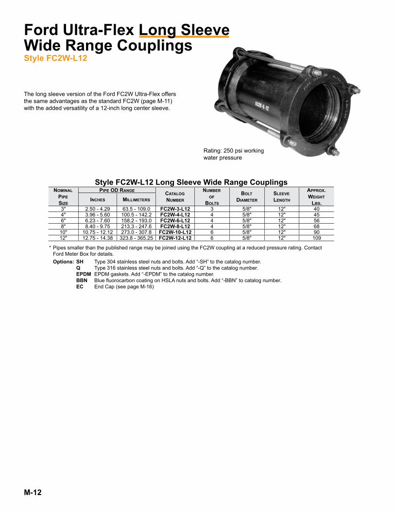
Ford Ultra-Flex Long SleeveWide Range CouplingsStyle FC2W-L12
The long sleeve version of the Ford FC2W Ultra-Flex offers the same advantages as the standard FC2W (page M-11) with the added versatility of a 12-inch long center sleeve .
Style FC2W-L12 Long Sleeve Wide Range CouplingsNomiNal<br/>
PiPe<br/>
Size
PiPe od raNge Catalog<br/>
Number
Number<br/>
of<br/>
boltS
bolt<br/>
diameterSleeve<br/>
leNgth
aPProx.<br/>
Weight<br/>
lbS.iNCheS millimeterS
3" 2 .50 - 4 .29 63 .5 - 109 .0 FC2W-3-L12 3 5/8" 12" 404" 3 .96 - 5 .60 100 .5 - 142 .2 FC2W-4-L12 4 5/8" 12" 456" 6 .23 - 7 .60 158 .2 - 193 .0 FC2W-6-L12 4 5/8" 12" 568" 8 .40 - 9 .75 213 .3 - 247 .6 FC2W-8-L12 4 5/8" 12" 6810" 10 .75 - 12 .12 273 .0 - 307 .8 FC2W-10-L12 6 5/8" 12" 9012" 12 .75 - 14 .38 323 .8 - 365 .25 FC2W-12-L12 6 5/8" 12" 109
Rating: 250 psi working water pressure
* Pipes smaller than the published range may be joined using the FC2W coupling at a reduced pressure rating . Contact Ford Meter Box for details . Options: SH Type 304 stainless steel nuts and bolts . Add “-SH” to the catalog number . Q Type 316 stainless steel nuts and bolts . Add “-Q” to the catalog number . EPDM EPDM gaskets . Add “-EPDM” to the catalog number . BBN Blue fluorocarbon coating on HSLA nuts and bolts . Add “-BBN” to catalog number . EC End Cap (see page M-16)

M-13
Ford Reducing CouplingStyle FRC
Ford Reducing Couplings are designed to connect different size water main pipes . Maximum pipe differential is one nominal pipe size . Material specifications for Style FRC Reducing Couplings are the same as those for Styles FC1 and FC2A Couplings . See page M-4 for details .
Larger, fabricated steel reducing couplings are detailed in Catalog Section N .
Caution: Restrain if necessary to provide thrust resistance . Flexible couplings do not prevent axial pipe movement .
Material Specifications: NBR (Buna-N) Rubber per ASTM D2000.
Ford Insulating BootsStyle FIB
Ford Insulating Boots are used to provide a break in electrical conductivity between metallic pipes in order to control corrosion . The 7" long rubber boot slides over the end of the pipe and prevents contact with adjoining pipe . The FIB adds .25" to the outside diameter of the pipe which is important to consider when ordering couplings.
The Ford FIB Place the FIB on one pipe end and the coupling on the adjoining pipe
Complete the installation according to the coupling instructions .
Insulating Boots - FIB
Nom. PiPe<br/>
SizePiPe<br/>
o.d. Catalog NumberaPProx.<br/>
Wt.<br/>
lbS.4" 4 .80 FIB-480 0 .76" 6 .90 FIB-690 1 .08" 9 .05 FIB-905 1 .3
10" 11 .10 FIB-1110 1 .612" 13 .20 FIB-1320 1 .9
To order: Locate the gasket range that accommodates your pipe O .D . for both types of pipe . Use the top range of each gasket size to identify the part number . For example, to connect pipe with an O .D . of 6 .63 to a pipe with an O .D . of 4 .50, the catalog number is FRC-676-460 .
Note: Additional sizes built to the same specification are available upon request .
Style FC1 for Cast, Ductile Iron or PVC PipeNom.<br/>
PiPe<br/>
Size
Catalog<br/>
Number<br/>
Prefix
gaSket raNge eNd riNg<br/>
Color<br/>
Codeby
gaSket raNge eNd riNg<br/>
Color<br/>
Code
Number<br/>
of<br/>
boltS
aPProx.<br/>
Weight<br/>
lbS
1St.<br/>half<br/>
Cat. No.2Nd half<br/>
Cat. No.
4"x3" FRC-
3 .95 — 4.05 Red 3 .45 — 3.60 Red
4 234 .45 — 4.60 Red 3 .70 — 3.88 Black4 .80 — 5.00 Black 3 .91 — 4.06 Black4 .92 — 5.16 Black 4 .07 — 4.20 White/Gray5 .17 — 5.32 White/Gray — -
6"x4" FRC-
5 .95 — 6.05 Red 3 .95 — 4.05 Red
5 376 .54 — 6.76 Red 4 .45 — 4.60 Red6 .81 — 7.12 Black 4 .70 — 4.91 Black7 .17 — 7.37 Black 4 .92 — 5.16 Black7 .37 — 7.60 White/Gray 5 .17 — 5.32 White/Gray
M-14
Rated working pressure: 175 PSI
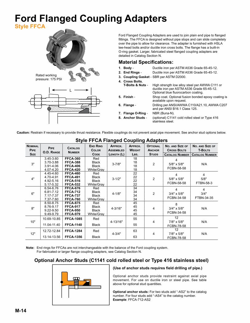
Ford Flanged Coupling AdaptersStyle FFCA
Ford Flanged Coupling Adapters are used to join plain end pipe to flanged fittings . The FFCA is designed without pipe stops and can slide completely over the pipe to allow for clearance . The adapter is furnished with HSLA tee-head bolts and/or ductile iron cross bolts . The flange has a built-in O-ring gasket . Larger, fabricated steel flanged coupling adapters are detailed in Catalog Section N .
Material Specifications:1 . Body - Ductile iron per ASTM A536 Grade 65-45-12 .2. End Rings - Ductile iron per ASTM A536 Grade 65-45-12 .3. Coupling Gasket - SBR per ASTM D2000 .4. Cross Bolts, T-Bolts & Nuts - High strength low alloy steel per AWWA C111 or ductile iron per ASTM A536 Grade 65-45-12 . Optional blue fluorocarbon coating .5. Finish - Shop coat . Optional fusion bonded epoxy coating is available upon request .6. Flange - Drilling per ANSI/AWWA C110/A21 .10, AWWA C207 and per ANSI B16 .1 Class 125 .7. Flange O-Ring - NBR (Buna-N) .8. Anchor Studs - (optional) C1141 cold rolled steel or Type 416 stainless steel .
L
Caution: Restrain if necessary to provide thrust resistance . Flexible couplings do not prevent axial pipe movement . See anchor stud options below .
Optional Anchor Studs (C1141 cold rolled steel or Type 416 stainless steel) (Use of anchor studs requires field drilling of pipe.)
Optional anchor studs provide restraint against axial pipe movement . For use on ductile iron or steel pipe . See table above for optional stud quantities .
Optional anchor studs: For two studs add “-AS2” to the catalog number . For four studs add “-AS4” to the catalog number .Example: FFCA-712-AS2
Note: End rings for FFCAs are not interchangeable with the balance of the Ford coupling system . For fabricated or larger flange coupling adapters, see Catalog Section N .
Style FFCA Flanged Coupling AdaptersNomiNal<br/>
PiPe<br/>
Size
PiPe<br/>
o.d. raNgeCatalog<br/>
Number
eNd riNg<br/>
Color<br/>
Code
aPProx.<br/>
aSSembled<br/>
leNgth (l)
aPProx.<br/>
Weight<br/>
lbS.
oPtioNal<br/>
aNChor<br/>
StudS
No. aNd Size of<br/>
CroSS boltSNo. aNd Size of<br/>
t-boltS
Catalog Number Catalog Number
3"
3 .45-3 .60 FFCA-360 Red
3-7/8"
18
24<br/>
5/8" x 5/8"<br/>
FCBN-58-58N/A3 .70-3 .88 FFCA-388 Black 18
3 .91-4 .06 FFCA-406 Black 184 .07-4 .20 FFCA-420 White/Gray 18
4"
4 .45-4 .60 FFCA-460 Red
3-1/2"
22
24<br/>
5/8" x 5/8"<br/>
FCBN-58-58
4<br/>
5/8"<br/>
FTBN-58-3
4 .70-4 .91 FFCA-491 Black 224 .92-5 .16 FFCA-516 Black 225 .17-5 .32 FFCA-532 White/Gray 22
6"
6 .54-6 .76 FFCA-676 Red
4-1/8"
34
24<br/>
3/4" x 5/8"<br/>
FCBN-34-58
4<br/>
3/4"<br/>
FTBN-34-35
6 .81-7 .12 FFCA-712 Black 347 .17-7 .37 FFCA-737 Black 347 .37-7 .60 FFCA-760 White/Gray 34
8"
8 .50-8 .75 FFCA-875 Red
4-3/16"
45
48<br/>
3/4" x 5/8"<br/>
FCBN-34-58N/A8 .76-9 .17 FFCA-917 Black 45
9 .22-9 .50 FFCA-950 Black 459 .49-9 .79 FFCA-979 White/Gray 45
10"10 .69-10 .85 FFCA-1085 Red
4-13/16"55
412<br/>
7/8" x 5/8"<br/>
FCBN-78-58N/A
11 .04-11 .40 FFCA-1140 Black 55
12"12 .72-12 .84 FFCA-1284 Red
4-3/4"63
412<br/>
7/8" x 5/8"<br/>
FCBN-78-58N/A
13 .14-13 .56 FFCA-1356 Black 63
M-15
Installation Instructions
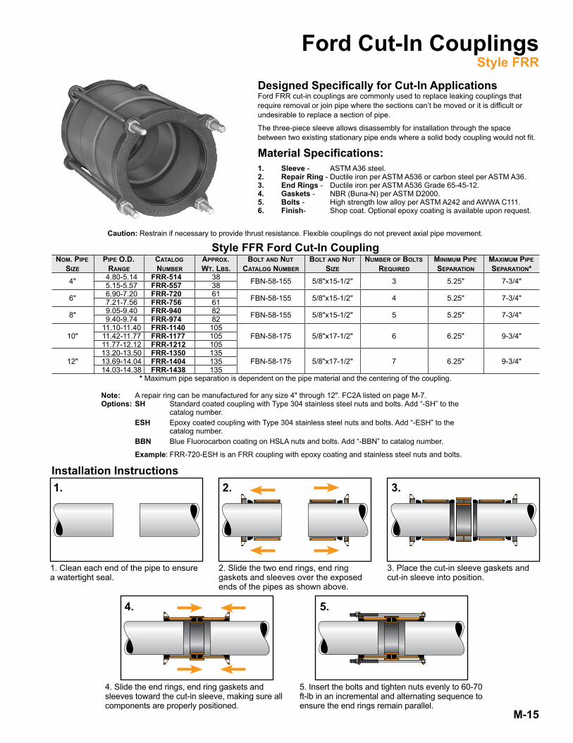
Ford Cut-In CouplingsStyle FRR
Designed Specifically for Cut-In ApplicationsFord FRR cut-in couplings are commonly used to replace leaking couplings that require removal or join pipe where the sections can’t be moved or it is difficult or undesirable to replace a section of pipe .
The three-piece sleeve allows disassembly for installation through the space between two existing stationary pipe ends where a solid body coupling would not fit .
Material Specifications:1. Sleeve - ASTM A36 steel .2. Repair Ring - Ductile iron per ASTM A536 or carbon steel per ASTM A36 .3. End Rings - Ductile iron per ASTM A536 Grade 65-45-12 .4. Gaskets - NBR (Buna-N) per ASTM D2000 .5. Bolts - High strength low alloy per ASTM A242 and AWWA C111 .6. Finish- Shop coat . Optional epoxy coating is available upon request .
Style FFR Ford Cut-In CouplingNom. PiPe<br/>
SizePiPe o.d.<br/>
raNgeCatalog<br/>
NumberaPProx.<br/>
Wt. lbS.bolt aNd Nut<br/>
Catalog Numberbolt aNd Nut<br/>
SizeNumber of boltS<br/>
requiredmiNimum PiPe<br/>
SeParatioNmaximum PiPe<br/>
SeParatioN*4" 4 .80-5 .14 FRR-514 38 FBN-58-155 5/8"x15-1/2" 3 5 .25" 7-3/4"5 .15-5 .57 FRR-557 38
6" 6 .90-7 .20 FRR-720 61 FBN-58-155 5/8"x15-1/2" 4 5 .25" 7-3/4"7 .21-7 .56 FRR-756 61
8" 9 .05-9 .40 FRR-940 82 FBN-58-155 5/8"x15-1/2" 5 5 .25" 7-3/4"9 .40-9 .74 FRR-974 82
10"11 .10-11 .40 FRR-1140 105
FBN-58-175 5/8"x17-1/2" 6 6 .25" 9-3/4"11 .42-11 .77 FRR-1177 10511 .77-12 .12 FRR-1212 105
12"13 .20-13 .50 FRR-1350 135
FBN-58-175 5/8"x17-1/2" 7 6 .25" 9-3/4"13 .69-14 .04 FRR-1404 13514 .03-14 .38 FRR-1438 135
* Maximum pipe separation is dependent on the pipe material and the centering of the coupling .
Note: A repair ring can be manufactured for any size 4" through 12" . FC2A listed on page M-7 .Options: SH Standard coated coupling with Type 304 stainless steel nuts and bolts . Add “-SH” to the catalog number . ESH Epoxy coated coupling with Type 304 stainless steel nuts and bolts . Add “-ESH” to the catalog number . BBN Blue Fluorocarbon coating on HSLA nuts and bolts . Add “-BBN” to catalog number .
Example: FRR-720-ESH is an FRR coupling with epoxy coating and stainless steel nuts and bolts .
Caution: Restrain if necessary to provide thrust resistance . Flexible couplings do not prevent axial pipe movement .
1.
1 . Clean each end of the pipe to ensure a watertight seal .
3.
3 . Place the cut-in sleeve gaskets and cut-in sleeve into position .
4.
4 . Slide the end rings, end ring gaskets and sleeves toward the cut-in sleeve, making sure all components are properly positioned .
5.
5 . Insert the bolts and tighten nuts evenly to 60-70 ft-lb in an incremental and alternating sequence to ensure the end rings remain parallel .
2.
2 . Slide the two end rings, end ring gaskets and sleeves over the exposed ends of the pipes as shown above .

M-16
ford eNd CaP CouPliNgS - Style feCNom. PiPe<br/>
SizePiPe o.d.<br/>
raNgeCatalog<br/>
NumberaPProx.<br/>
Wt. lbS.eNd CaP oNly (iNCludeS gaSket) Number of boltS<br/>
requiredfC1 CouPliNg fC2a CouPliNg
4"4 .00 FEC-400
21 FEC1-4 FEC2-4 34 .50 FEC-4504 .80-5 .14 FEC-5145 .15-5 .57 FEC-557
6"6 .00 FEC-600
31 FEC1-6 FEC2-6 46 .63 FEC-6636 .90-7 .20 FEC-7207 .21-7 .56 FEC-756
8"8 .00 FEC-800
41 FEC1-8 FEC2-8 58 .63 FEC-8639 .05-9 .40 FEC-9409 .40-9 .74 FEC-974
10" 11 .10-11 .40 FEC-1140 55 FEC1-10 FEC2-10 611 .77-12 .12 FEC-121212" 13 .20-13 .50 FEC-1350 66 FEC1-12 FEC2-12 7
Ford End Cap CouplingsStyle FEC The FEC Ford End Cap Coupling is provided with a 2" female iron pipe threaded boss (less the pipe
plug) . The boss is located in the center as standard; optional locations are available . Blind end caps may be furnished upon request .
Material Specifications:1. Sleeve - Ductile iron per ASTM A536, Grade 65-45-12 .2. End Rings - Ductile iron per ASTM A536, Grade 65-45-12 .3. Gaskets - NBR (Buna-N) per ASTM D2000 .4. End Cap - Carbon steel per ASTM A36 with 2" female iron pipe threaded boss .5. Bolts - High strength low alloy per ASTM A242 and AWWA C111 .6. Finish - Shop coat . Optional epoxy coating is available upon request .Caution: Restrain if necessary to provide thrust resistance . Flexible couplings do not prevent axial pipe movement .
Ford End Cap for Ultra-Flex Wide Range CouplingsStyle FC2W-EC
The FC2W-EC Ford End Cap Coupling is provided with a 2" female iron pipe threaded boss (less the pipe plug) . The boss is located in the center as standard; optional locations are available on 10" and 12" end caps .
Material Specifications:1. Sleeve - Ductile iron per ASTM A536, Grade 65-45-12 .2. End Rings - Ductile iron per ASTM A536, Grade 65-45-12 .3. Gaskets - NBR (Buna-N) per ASTM D2000 .4. End Cap - Ductile iron per ASTM A536, Grade 65-45-12 or carbon steel per ASTM A36 .5. Bolts - High strength low alloy per ASTM A242 and AWWA C111 .6. Finish - Sleeve and end rings are epoxy coated . 4", 6" and 8" e-coat epoxy end caps 10" and 12" epoxy coated end caps
Ford Ultra-Flex Long Sleeve Wide Range CouplingsStyle FC2W-EC (12" Long)
Style fC2W-eCNom. PiPe Size
PiPe o.d. raNge Catalog Number aPProx Wt. lbS. eNd CaP oNly eNd CaP Wt. lbS.iNCheS Millimeters4" 3 .96-5 .60 100 .5 - 142 .2 FC2W-4-EC 44 FECW-4 96" 6 .23-7 .60 158 .2 - 193 .0 FC2W-6-EC 57 FECW-6 138" 8 .40-9 .75 213 .3 - 247 .6 FC2W-8-EC 75 FECW-8 23
10" 10 .77-12 .12 273 .0 - 307 .8 FC2W-10-EC 138 FECW-10 6212" 12 .75-14 .38 323 .8 - 365 .25 FC2W-12-EC 178 FECW-12 80
Style fC2W-eC (12" loNg)Nom. PiPe Size
PiPe od raNge Catalog NumberSleeve<br/>
leNgthaPProx. Wt. lbS. eNd CaP oNly eNd CaP Wt. lbS.iNCheS millimeterS
4" 3 .96 - 5 .60 100 .5 - 142 .2 FC2W-4-L12-EC 12" 54 FECW-4 96" 6 .23 - 7 .60 158 .2 - 193 .0 FC2W-6-L12-EC 12" 69 FECW-6 138" 8 .40 - 9 .75 213 .3 - 247 .6 FC2W-8-L12-EC 12" 91 FECW-8 2310" 10 .75 - 12 .12 273 .0 - 307 .8 FC2W-10-L12-EC 12" 152 FECW-10 6212" 12 .75 - 14 .38 323 .8 - 365 .25 FC2W-12-L12-EC 12" 189 FECW-12 80
Note: Larger fabricated end cap couplings are listed in Section “N” .Options: SH Standard coated coupling with Type 304 stainless steel nuts and bolts . Add “-SH” to the catalog number . ESH Epoxy coated coupling with Type 304 stainless steel nuts and bolts . Add “-ESH” to the catalog number . BBN Blue fluorocarbon coating on HSLA nuts and bolts . Add “-BBN” to catalog number . BEC Blind End Cap, no female iron pipe threads . Add “-BEC” to the catalog number . EPDM EPDM gasket . Add “-EPDM” to the catalog number . (Contact factory for Type 316 stainless steel nuts and bolts .)Example: FEC-720-ESH is an FEC coupling with epoxy coating and stainless steel nuts and bolts .

M-17
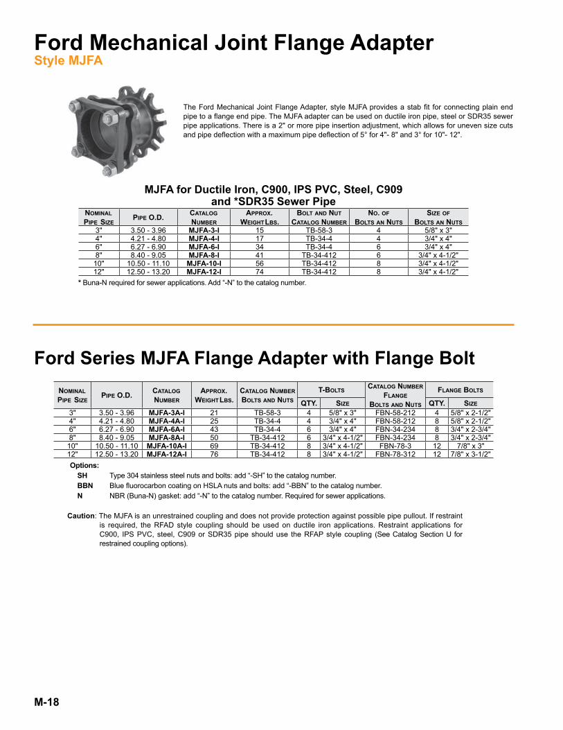
Ford Mechanical Joint Flange AdapterStyle MJFA
Ford offers a true stab fit for connecting plain end pipe to a flange end pipe with the MJFA style adapter .
Two closed starter lugs,(one at top and one on bottom)
Tee-head bolts and nuts are made of high strength, low alloy steel, per ASTM A242 and AWWA C111 . Optional blue fluorocarbon coated or stainless steel .
Gaskets are pre-lubricated SBR rubber (SO-EZ gasket)Optional NBR (Buna-N) rubber (SO-EZ gasket)
Flange O-ring is NBR(ASTM D2000)
Flange adapter sleeve is ductile iron per ASTM A536, compatible with Class D or Class E Flange per AWWA C207 with a fusion bonded epoxy coating .
Center sleeve and MJ gland are ductile iron perASTM A536, Grade 65-45-12
Component Specifications: Flanged Adapter Sleeve: Ductile iron per ASTM A536, compatible with Class D or Class E flange, per AWWA C207 with a fusion bonded epoxy coating . Flange O-ring: NBR (Buna-N per ASTM D2000) . Tee-head Bolts and Nuts: High strength low alloy steel, per ASTM A242 and AWWA C111 Optional: Blue fluorocarbon coated or stainless steel MJ Gland: Black e-coated, ductile iron per ASTM A536 Gasket: Pre-lubricated SBR rubber (SO-EZ gasket) Optional: NBR (Buna-N) rubber (SO-EZ gasket) required for sewer applications .
MJFA for Ductile Iron, C900 PVC, IPS PVC, Steel,C909 PVC and SDR35 Sewer Pipe
NomiNal<br/>
PiPe<br/>
Size
Catalog<br/>
NumberPiPe o.d.
dimeNSioN"a" miNimum
PiPe iNSertioN
dimeNSioN"b" miNimum
PiPe iNSertioN
max.defleCtioNalloWaNCe
aPProx.<br/>
Weight<br/>
lbS.3" MJFA-3-I *3 .50 - 3 .96 *3-7/8" *1-7/8" 5° 154" MJFA-4-I *4 .21 - 4 .80 *4-3/8" *2" 5° 176" MJFA-6-I *6 .27 - 6 .90 *4-5/8" *2-7/8" 5° 348" MJFA-8-I *8 .40 - 9 .05 *4-11/16" *3" 5° 4110" MJFA-10-I *10 .50 - 11 .10 *4-11/16" *3-3/8" 3° 5612" MJFA-12-I *12 .50 - 13 .20 *4-11/16" *3-5/8" 3° 74
Pressure Rating for C900 PVC, IPS PVC, C909 PVCand SDR35 Sewer Pipe
C900 aStm d2241 C909 Sdr35DR25 DR18 DR14 SDR26 SDR21 PC150
165 PSI 235 PSI 305 PSI 160 PSI 200 PSI 150 PSI PS> 46 PSI
* Not accounting for beveled, unsquare or deflected pipe ends .
"A" "B"
Caution: Restrain if necessary to provide thrust resistance . Flexible couplings do not prevent axial pipe movement .
M-18
Ford Mechanical Joint Flange AdapterStyle MJFA
The Ford Mechanical Joint Flange Adapter, style MJFA provides a stab fit for connecting plain end pipe to a flange end pipe . The MJFA adapter can be used on ductile iron pipe, steel or SDR35 sewer pipe applications . There is a 2" or more pipe insertion adjustment, which allows for uneven size cuts and pipe deflection with a maximum pipe deflection of 5° for 4"- 8" and 3° for 10"- 12" .
MJFA for Ductile Iron, C900, IPS PVC, Steel, C909and *SDR35 Sewer Pipe
NomiNal<br/>
PiPe<br/> SizePiPe o.d. Catalog<br/>
NumberaPProx.<br/>
Weight<br/>lbS.bolt aNd Nut
Catalog NumberNo. of
boltS aN NutSSize of
boltS aN NutS3" 3 .50 - 3 .96 MJFA-3-I 15 TB-58-3 4 5/8" x 3"4" 4 .21 - 4 .80 MJFA-4-I 17 TB-34-4 4 3/4" x 4"6" 6 .27 - 6 .90 MJFA-6-I 34 TB-34-4 6 3/4" x 4"8" 8 .40 - 9 .05 MJFA-8-I 41 TB-34-412 6 3/4" x 4-1/2"10" 10 .50 - 11 .10 MJFA-10-I 56 TB-34-412 8 3/4" x 4-1/2"12" 12 .50 - 13 .20 MJFA-12-I 74 TB-34-412 8 3/4" x 4-1/2"
Ford Series MJFA Flange Adapter with Flange BoltNomiNal<br/>
PiPe<br/> SizePiPe o.d. Catalog<br/>
NumberaPProx.<br/>
Weight<br/>lbS.Catalog NumberboltS aNd NutS
t-boltS Catalog NumberflaNge
boltS aNd NutS
flaNge boltS
qty. Size qty. Size3" 3 .50 - 3 .96 MJFA-3A-I 21 TB-58-3 4 5/8" x 3" FBN-58-212 4 5/8" x 2-1/2"4" 4 .21 - 4 .80 MJFA-4A-I 25 TB-34-4 4 3/4" x 4" FBN-58-212 8 5/8" x 2-1/2"6" 6 .27 - 6 .90 MJFA-6A-I 43 TB-34-4 6 3/4" x 4" FBN-34-234 8 3/4" x 2-3/4"8" 8 .40 - 9 .05 MJFA-8A-I 50 TB-34-412 6 3/4" x 4-1/2" FBN-34-234 8 3/4" x 2-3/4"
10" 10 .50 - 11 .10 MJFA-10A-I 69 TB-34-412 8 3/4" x 4-1/2" FBN-78-3 12 7/8" x 3"12" 12 .50 - 13 .20 MJFA-12A-I 76 TB-34-412 8 3/4" x 4-1/2" FBN-78-312 12 7/8" x 3-1/2"Options: SH Type 304 stainless steel nuts and bolts: add “-SH” to the catalog number . BBN Blue fluorocarbon coating on HSLA nuts and bolts: add “-BBN” to the catalog number . N NBR (Buna-N) gasket: add “-N” to the catalog number . Required for sewer applications .
Caution: The MJFA is an unrestrained coupling and does not provide protection against possible pipe pullout . If restraint is required, the RFAD style coupling should be used on ductile iron applications . Restraint applications for C900, IPS PVC, steel, C909 or SDR35 pipe should use the RFAP style coupling (See Catalog Section U for restrained coupling options) .
* Buna-N required for sewer applications . Add “-N” to the catalog number .

M-19
Ford Mechanical Joint CouplingStyle MJC
Joining plain end pipe is so easy when using Ford’s MJC coupling . The standard coupling includes the SO-EZ gasket that permits a stab fit for a wide range within a nominal size pipe .
Gaskets are pre-lubricated SBR rubber (SO-EZ gasket) Optional NBR (Buna-N) rubber (SO-EZ gasket)
MJ glands are ductile iron per ASTM A536 with a black e-coat epoxy coating
MJ Coupling Sleeves are ductile iron per ASTM A536 with a fusion bonded epoxy coating
Double ended rods and nuts are made of high strength, low allow steel, per ASTM A242, and AWWA C111 . Optional blue fluorocarbon coating or stainless steel .
Component Specifications: MJ Coupling Sleeve: Fusion bonded epoxy ductile iron per ASTM A536 Double-ended Rods and Nuts: High strength low alloy steel per ASTM A242 and AWWA C111 Optional: blue fluorocarbon coated or stainless steel MJ Gland: Black e-coated, ductile iron per ASTM A536 Gasket: Pre-lubricated SBR rubber (SO-EZ gasket) Optional: NBR (Buna-N) rubber (SO-EZ gasket) required for sewer applications .
MJC for Ductile Iron, C900, IPS PVC, Steel, C909 and **SDR35 Sewer PipeNomiNal<br/>
PiPe<br/> SizeCatalog<br/>
NumberPiPe o.d. dimeNSioN “a”
miNimum PiPe iNSertioNmax. defleCtioN
alloWaNCeaPProx.<br/>
Weight<br/>lbS.3" MJC-3-U 3 .50 - 3 .96 4" 5° 214" MJC-4-I *4 .21 - 4 .80 *4-5/8" 5° 256" MJC-6-I *6 .27 - 6 .90 *4-3/4" 5° 438" MJC-8-I *8 .40 - 9 .05 *4-13/16" 5° 50
10" MJC-10-I *10 .50 - 11 .10 *4-7/8" 5° 6912" MJC-12-I *12 .50 - 13 .20 *4-7/8" 5° 76
* Not accounting for beveled, unsquare or deflected pipe ends .**Buna-N gasket required for sewer applications .Larger fabricated sizes are available, contact factory for more information .
Pressure Rating for C900, IPS PVC, C909 and **SDR35 Sewer PipeC900 aStm d2241 C909 Sdr35
DR25 DR18 DR14 SDR26 SDR21 PC150165 PSI 235 PSI 305 PSI 160 PSI 200 PSI 150 PSI PS> 46 PSI
I = Import Casting U = Domestic Casting
Caution: Restrain if necessary to provide thrust resistance . Flexible couplings do not prevent axial pipe movement .

M-20
Ford Mechanical Joint CouplingStyle MJC
Joining plain end pipe is so easy when using Ford’s MJC coupling . The standard coupling includes the SO-EZ gasket that permits a stab fit for a wide range within a nominal size pipe .
The MJC coupling has a 2:1 safety factor at the full rated pressure of the pipe on which it is installed .
Style MJC Coupling for Ductile Iron, C900, IPS, Steel, C909 and *SDR35 Sewer PipeNomiNal<br/>
PiPe<br/> SizePiPe o.d. Catalog<br/> Number
rodS aNd NutS aPProx.<br/>
Weight<br/>lbS.qty. Size3" 3 .50 - 3 .96 MJC-3-U 4 5/8" x 14" 214" *4 .21 - 4 .80 MJC-4-I 4 3/4" x 14" 256" *6 .27 - 6 .90 MJC-6-I 6 3/4" x 14" 438" *8 .40 - 9 .05 MJC-8-I 6 3/4" x 14" 50
10" *10 .50 - 11 .10 MJC-10-I 8 3/4" x 14" 6912" *12 .50 - 13 .20 MJC-12-I 8 3/4" x 14" 76
Component Parts for Style MJC CouplingsNomiNalPiPe Size
**Sleeve kitSmJ CouPliNg
SleeveCatalog Number
gaSketCatalog Number
rodCatalog Number
rodSize
Number of rodS
NutSNumber of
NutS
3" RCAK-3 MJCS-3-U SO-EZ-3 DER-58-14 5/8" x 14" 4 HHN-58 84" RCAK-4 MJCS-4-I SO-EZ-4 DER-34-14 3/4" x 14" 4 HHN-34 86" RCAK-6 MJCS-6-I SO-EZ-6 DER-34-14 3/4" x 14" 6 HHN-34 128" RCAK-8 MJCS-8-I SO-EZ-8 DER-34-14 3/4" x 14" 6 HHN-34 1210" RCAK-10 MJCS-10-I SO-EZ-10 DER-34-14 3/4" x 14" 8 HHN-34 1612" RCAK-12 MJCS-12-I SO-EZ-12 DER-34-14 3/4" x 14" 8 HHN-34 16
** Includes center sleeve, rods, nuts and bolts .
Options: SH Type 304 stainless steel nuts and bolts: add “-SH” to the catalog number . BBN Blue fluorocarbon coating on HSLA nuts and bolts: add “-BBN” to the catalog number . * N NBR (Buna-N) gasket: add “-N” to the catalog number . Required for sewer applications . I = Import Casting U = Domestic Casting
M-21
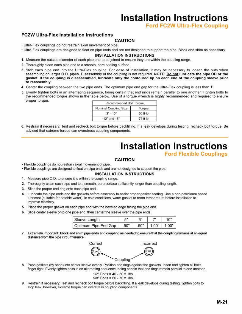
FC2W Ultra-Flex Installation Instructions CAUTION
• Ultra-Flex couplings do not restrain axial movement of pipe .• Ultra-Flex couplings are designed to float on pipe ends and are not designed to support the pipe . Block and shim as necessary .
INSTALLATION INSTRUCTIONS1. Measure the outside diameter of each pipe end to be joined to ensure they are within the coupling range .2. Thoroughly clean each pipe end to a smooth, bare sealing surface . 3. Stab each pipe end into the Ultra-Flex coupling . For ease of installation, it may be necessary to loosen the nuts when
assembling on larger O .D . pipes . Disassembly of the coupling is not required . NOTE: Do not lubricate the pipe OD or the gasket. If the coupling is disassembled, lubricate only the contoured lip on each end of the coupling sleeve prior to reassembly.
4. Center the coupling between the two pipe ends . The optimum pipe end gap for the Ultra-Flex coupling is less than 1” .5. Evenly tighten bolts in an alternating sequence, being certain that end rings remain parallel to one another . Tighten bolts to
the recommended torque shown in the table below . Use of a torque wrench is highly recommended and required to ensure proper torque .
6. Restrain if necessary . Test and recheck bolt torque before backfilling . If a leak develops during testing, recheck bolt torque . Be advised that extreme torque can overstress coupling components .
Recommended Bolt TorqueNominal Coupling Size Torque
3" - 10" 50 ft-lb12" and 16" 75 ft-lb
Installation InstructionsFord Flexible Couplings
CAUTION• Flexible couplings do not restrain axial movement of pipe .• Flexible couplings are designed to float on pipe ends and are not designed to support the pipe .
INSTALLATION INSTRUCTIONS1. Measure pipe O .D . to ensure it is within the coupling range .2. Thoroughly clean each pipe end to a smooth, bare surface sufficiently longer than coupling length .3. Slide the proper end ring onto each pipe end .4. Lubricate the pipe ends and the gaskets before assembly to assist proper gasket seating . Use a non-petroleum based lubricant (suitable for potable water) . In cold conditions, warm gasket to room temperature before installation to improve elasticity .5. Place the proper gasket on each pipe end with the beveled edge facing the pipe end . 6. Slide center sleeve onto one pipe end, then center the sleeve over the pipe ends .
7. Extremely Important: Block and shim pipe ends and coupling as needed to ensure that the coupling remains at an equal distance from the pipe circumference.
8. Push gaskets (by hand) into center sleeve evenly . Position end rings against the gaskets . Insert and tighten all bolts finger tight . Evenly tighten bolts in an alternating sequence, being certain that end rings remain parallel to one another . 1/2" Bolts = 40 - 50 ft . lbs . 5/8" Bolts = 60 - 70 ft . lbs .9. Restrain if necessary . Test and recheck bolt torque before backfilling . If a leak develops during testing, tighten bolts to stop leak; however, extreme torque can overstress coupling components .
Sleeve Length 5" 6" 7" 10"Optimum Pipe End Gap .50" .50" 1 .00" 1 .00"
IncorrectCorrect
Coupling
PipePipe
Installation InstructionsFord FC2W Ultra-Flex Coupling

M-22
Stainless Steel InsertsFor HDPE Pipe
Nom. PiPe Size *Catalog Number leNgth aPProx. Wt. lbS.3" INSERT-3-xxxx **6" 1 .24" INSERT-4-xxxx
7-3/8"
1 .56" INSERT-6-xxxx 2 .18" INSERT-8-xxxx 2 .8
10" INSERT-10-xxxx 3 .512" INSERT-12-xxxx 4 .114" INSERT-14-xxxx 4 .816" INSERT-16-xxxx 5 .518" INSERT-18-xxxx 6 .120" INSERT-20-xxxx 6 .824" INSERT-24-xxxx 8 .130" INSERT-30-xxxx 10 .136" INSERT-36-xxxx 11 .5
I N S E R T - 8 - 7 3 0 5 - Q
Optional316 StainlessSteel
MeasuredPipe I .D .
** 3" inserts with I .D . larger than 3 .30" will be 7-3/8" length * When ordering, the pipe inside diameter is required . For example, when ordering for an 8" pipe with an I .D . of 7 .305", the part number is INSERT-8-7305 .
NominalPipe Size
Ford stainless steel inserts prevent HDPE pipe from losing rigidity on the end while also keeping the gasket or restraint functioning properly on the pipe . With one end tapered and a lip on the other, the solid design is easy to install and can't be over-inserted .
Features: ● Solid design on 4" and larger sizes (most 3" inserts are wedge design)● Type 304 stainless steel per ASTM A240 (with optional 316 stainless steel) • 20 gauge for 3", 4" and 6" solid design • 18 gauge for 8" and up● Chemically passivated to restore natural corrosion-resistant state● Durable, ergonomic design allows for a simple installation and long-lasting life
M-23
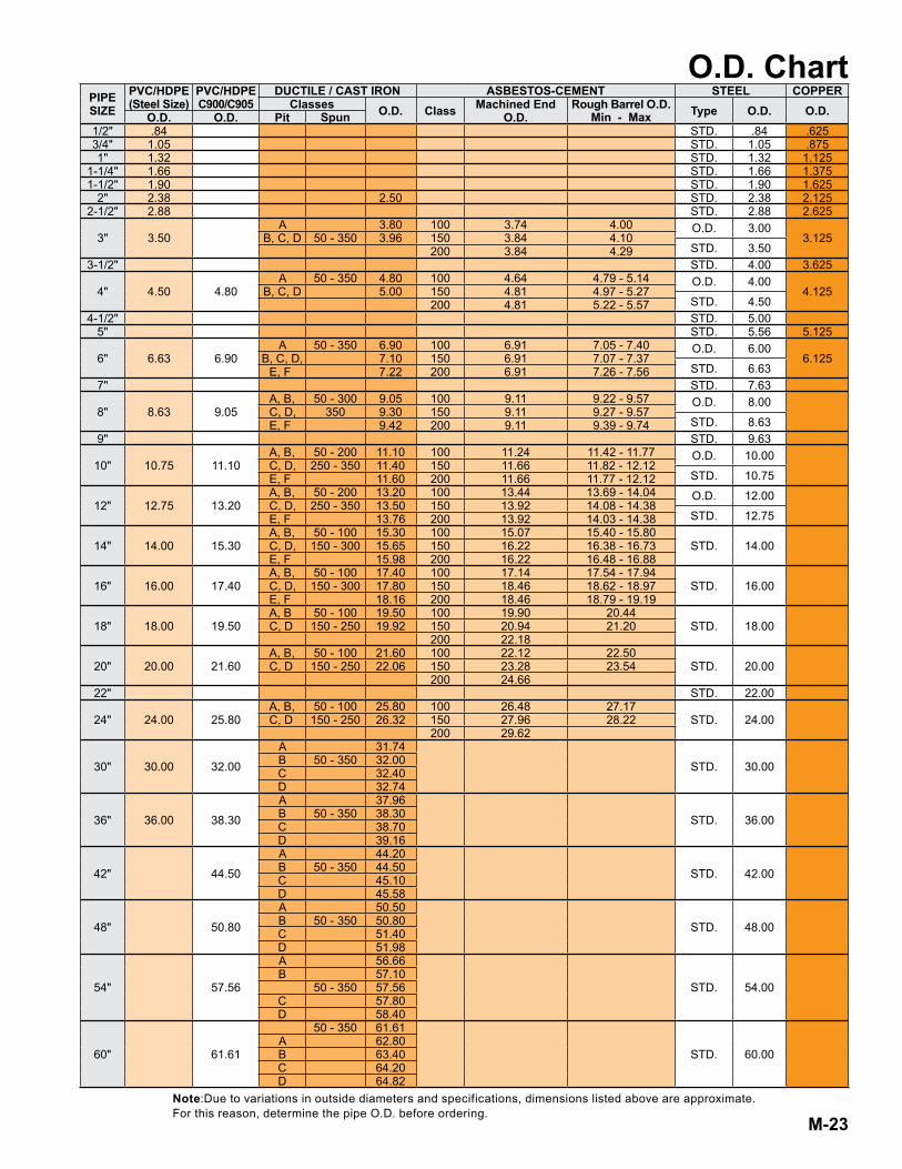
O.D. Chart
Note:Due to variations in outside diameters and specifications, dimensions listed above are approximate . For this reason, determine the pipe O .D . before ordering .
PIPESIZE
PVC/HDPE(Steel Size)
PVC/HDPEC900/C905
DUCTILE / CAST IRON ASBESTOS-CEMENT STEEL COPPERClasses O.D. Class Machined End
O.D.Rough Barrel O.D.
Min - Max Type O.D. O.D.O.D. O.D. Pit Spun1/2" .84 STD . .84 .6253/4" 1 .05 STD . 1 .05 .8751" 1 .32 STD . 1 .32 1 .125
1-1/4" 1 .66 STD . 1 .66 1 .3751-1/2" 1 .90 STD . 1 .90 1 .625
2" 2 .38 2 .50 STD . 2 .38 2 .1252-1/2" 2 .88 STD . 2 .88 2 .625
3" 3 .50A 3 .80 100 3 .74 4 .00 O .D . 3 .00
3 .125B, C, D 50 - 350 3 .96 150 3 .84 4 .10STD . 3 .50200 3 .84 4 .29
3-1/2" STD . 4 .00 3 .625
4" 4 .50 4 .80A 50 - 350 4 .80 100 4 .64 4 .79 - 5 .14 O .D . 4 .00
4 .125B, C, D 5 .00 150 4 .81 4 .97 - 5 .27STD . 4 .50200 4 .81 5 .22 - 5 .57
4-1/2" STD . 5 .005" STD . 5 .56 5 .125
6" 6 .63 6 .90A 50 - 350 6 .90 100 6 .91 7 .05 - 7 .40 O .D . 6 .00
6 .125B, C, D, 7 .10 150 6 .91 7 .07 - 7 .37STD . 6 .63E, F 7 .22 200 6 .91 7 .26 - 7 .56
7" STD . 7 .63
8" 8 .63 9 .05A, B, 50 - 300 9 .05 100 9 .11 9 .22 - 9 .57 O .D . 8 .00C, D, 350 9 .30 150 9 .11 9 .27 - 9 .57
STD . 8 .63E, F 9 .42 200 9 .11 9 .39 - 9 .749" STD . 9 .63
10" 10 .75 11 .10A, B, 50 - 200 11 .10 100 11 .24 11 .42 - 11 .77 O .D . 10 .00C, D, 250 - 350 11 .40 150 11 .66 11 .82 - 12 .12
STD . 10 .75E, F 11 .60 200 11 .66 11 .77 - 12 .12
12" 12 .75 13 .20A, B, 50 - 200 13 .20 100 13 .44 13 .69 - 14 .04 O .D . 12 .00C, D, 250 - 350 13 .50 150 13 .92 14 .08 - 14 .38
STD . 12 .75E, F 13 .76 200 13 .92 14 .03 - 14 .38
14" 14 .00 15 .30A, B, 50 - 100 15 .30 100 15 .07 15 .40 - 15 .80
STD . 14 .00C, D, 150 - 300 15 .65 150 16 .22 16 .38 - 16 .73E, F 15 .98 200 16 .22 16 .48 - 16 .88
16" 16 .00 17 .40A, B, 50 - 100 17 .40 100 17 .14 17 .54 - 17 .94
STD . 16 .00C, D, 150 - 300 17 .80 150 18 .46 18 .62 - 18 .97E, F 18 .16 200 18 .46 18 .79 - 19 .19
18" 18 .00 19 .50A, B 50 - 100 19 .50 100 19 .90 20 .44
STD . 18 .00C, D 150 - 250 19 .92 150 20 .94 21 .20200 22 .18
20" 20 .00 21 .60A, B, 50 - 100 21 .60 100 22 .12 22 .50
STD . 20 .00C, D 150 - 250 22 .06 150 23 .28 23 .54200 24 .66
22" STD . 22 .00
24" 24 .00 25 .80A, B, 50 - 100 25 .80 100 26 .48 27 .17
STD . 24 .00C, D 150 - 250 26 .32 150 27 .96 28 .22200 29 .62
30" 30 .00 32 .00
A 31 .74
STD . 30 .00B 50 - 350 32 .00C 32 .40D 32 .74
36" 36 .00 38 .30
A 37 .96
STD . 36 .00B 50 - 350 38 .30C 38 .70D 39 .16
42" 44 .50
A 44 .20
STD . 42 .00B 50 - 350 44 .50C 45 .10D 45 .58
48" 50 .80
A 50 .50
STD . 48 .00B 50 - 350 50 .80C 51 .40D 51 .98
54" 57 .56
A 56 .66
STD . 54 .00B 57 .10
50 - 350 57 .56C 57 .80D 58 .40
60" 61 .61
50 - 350 61 .61
STD . 60 .00A 62 .80B 63 .40C 64 .20D 64 .82

Section MFordCast Couplingsand Adapters
The Ford Meter Box Co., Inc. 775 Manchester Avenue, P .O . Box 443, Wabash, Indiana, USA 46992-0443Telephone: 260-563-3171 ● FAX: 800-826-3487 ● Overseas FAX: 260-563-0167 ● www .fordmeterbox .com
06/2017 - 2 .5M Parrot Press
Please Note:Consult The Ford Meter Box Company, Inc . website (www .fordmeterbox .com) for the most recent catalog information . The Ford Meter Box Company considers the information in this catalog to be correct at the time of publication . Items and option availability, including specifications, are subject to change without notice . Please verify that your product information is current .
Warranty All merchandise is warranted to be free from defects in material and factory workmanship for one year from date of shipment from our factory . We will provide, free of charge, new products in equal quantities for any that prove defective within one year from date of shipment from our factory . Manufacturer shall not be liable for any loss, damage, or injury, direct or consequential, arising out of the use of or the inability to use the product . Before using, user shall determine the suitability of the product for user’s intended use and user assumes all risk and liability whatever in connection therewith . No claims for labor or consequential damage will be allowed . The foregoing may not be changed except by agreement signed by an officer of the manufacturer .
No other warranties are applicable or may be implied, including the implied warranty of merchantability and the implied warranty of fitness for particular purpose and any warranty relating to infringement or the like, all of which are disclaimed .