ford f350 super duty chassis cabs 1999-2007 models w/ dana 80 … · ford f350 super duty chassis...
TRANSCRIPT
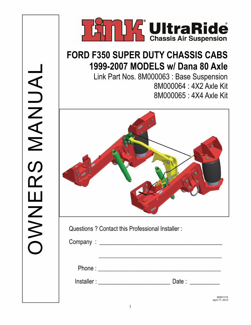
FORD F350 SUPER DUTY CHASSIS CABS 1999-2007 MODELS w/ Dana 80 Axle
Link Part Nos. 8M000063 : Base Suspension 8M000064 : 4X2 Axle Kit 8M000065 : 4X4 Axle Kit
80001174 April 17, 2012
OW
NE
RS
MA
NU
AL
Questions ? Contact this Professional Installer :
Company : _________________________________________
_________________________________________
Phone : _________________________________________
Installer : ________________________ Date : __________
1
INSTALLATION INSTRUCTIONS INDEX 1.0 INTRODUCTION 2.0 DRIVER SIDE DISASSEMBLY 3.0 DRIVER SIDE ASSEMBLY 4.0 PASSENGER SIDE DISASSEMBLY 5.0 PASSENGER SIDE ASSEMBLY 6.0 LATERAL CONTROL ROD 7.0 AIR CONTROL SYSTEM 8.0 ELECTRICAL 9.0 FINAL INSPECTION CHECKLIST 10.0 OPERATION GUIDELINES 11.0 SERVICE & MAINTENANCE
2
1. INTRODUCTION
IMPORTANT! It is important that the entire installation instructions be read thoroughly before proceeding with suspension installation.
PRODUCT INSTALLER RESPONSIBILITIES Installer is responsible for installing the product in accordance with Link Mfg. specifications and
installation instructions. Installer is responsible for providing proper vehicle components and attachments as well as
required or necessary clearance for suspension components, axles, wheels, tires, and other vehicle components to ensure a safe and sound installation and operation.
Installer is responsible for advising the owner of proper use, service and maintenance required by the product and for supplying maintenance and other instruction as readily available from Link Mfg..
INSTALLATION NOTES:
Fastener Specifications and Notes Proper tightening of U-Bolt nuts and mounting nuts are required for proper operation. Need for proper Torque value is indicated by wrench symbol and values will be found in
Table 10-1 in Maintenance section of the instructions. Failure to maintain proper torque can cause component failure resulting in accident with
consequent injury. To ensure that proper torque procedure has been followed you will be asked to paint scribe
each fastener after final torque has been applied. This will also provide for a visual check during vehicle servicing intervals.
Drilling of new frame holes is required for installation of the suspension.
NOTE: Exhaust modification will be required for this suspension installation. Parts and modifications are not included with the suspension.
Minimum clearances required for proper suspension operation Between Exhaust and Air Spring : 3 inches (unless heat shield is provided) Between Tire and Air Spring : 1.5 inches. Between Exhaust and any suspension hard point : 1.0 inch
(e.g. Lateral Control Rod)
WARNING! A correct installation must result in the suspension and axle being “loaded” within the range specified by axle and suspension manufacturers. Please check vehicle specifications and intended usage to insure axle will be
within Gross Axle Weight Rating (GAWR). No alteration of any suspension component is permitted. Link Mfg. Is not responsible for damages from improper installation or opera-tions beyond design capability. Link Mfg. In its sole discretion shall determine whether or not any product is defective or otherwise covered by warranty.
3
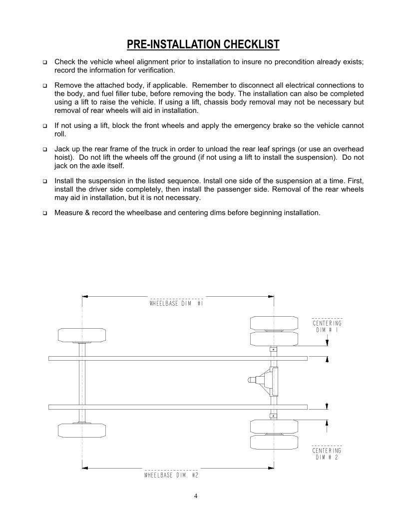
PRE-INSTALLATION CHECKLIST Check the vehicle wheel alignment prior to installation to insure no precondition already exists;
record the information for verification.
Remove the attached body, if applicable. Remember to disconnect all electrical connections to the body, and fuel filler tube, before removing the body. The installation can also be completed using a lift to raise the vehicle. If using a lift, chassis body removal may not be necessary but removal of rear wheels will aid in installation.
If not using a lift, block the front wheels and apply the emergency brake so the vehicle cannot roll.
Jack up the rear frame of the truck in order to unload the rear leaf springs (or use an overhead hoist). Do not lift the wheels off the ground (if not using a lift to install the suspension). Do not jack on the axle itself.
Install the suspension in the listed sequence. Install one side of the suspension at a time. First, install the driver side completely, then install the passenger side. Removal of the rear wheels may aid in installation, but it is not necessary.
Measure & record the wheelbase and centering dims before beginning installation.
4
2. DRIVER SIDE DISASSEMBLY
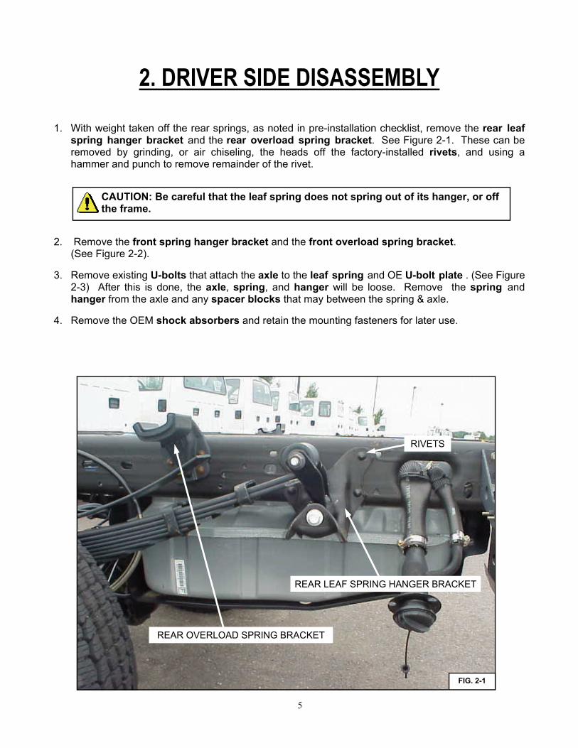
1. With weight taken off the rear springs, as noted in pre-installation checklist, remove the rear leaf spring hanger bracket and the rear overload spring bracket. See Figure 2-1. These can be removed by grinding, or air chiseling, the heads off the factory-installed rivets, and using a hammer and punch to remove remainder of the rivet.
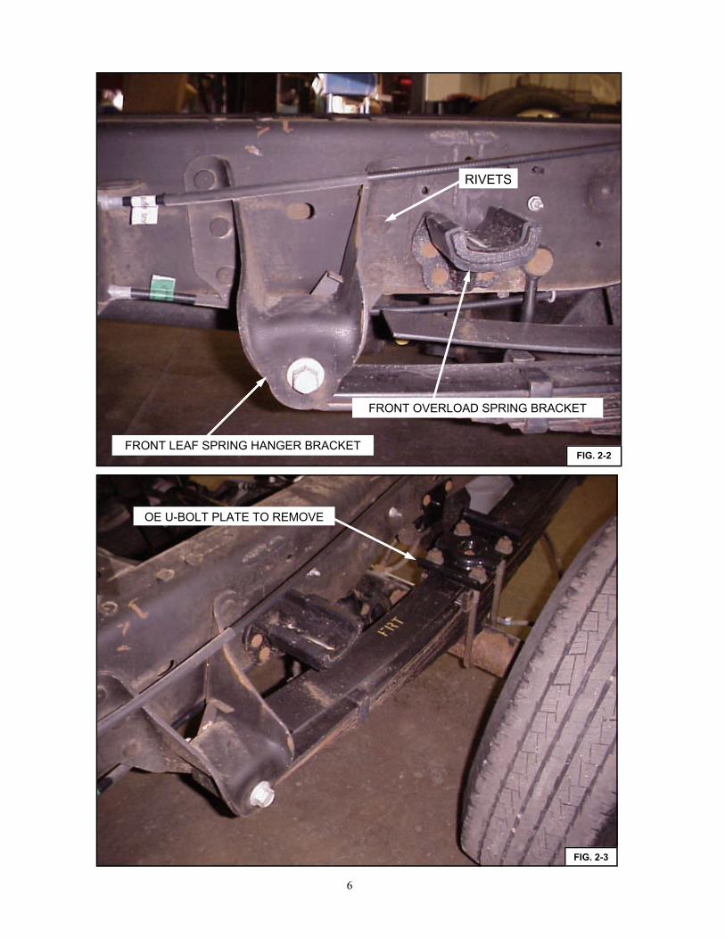
2. Remove the front spring hanger bracket and the front overload spring bracket. (See Figure 2-2).
3. Remove existing U-bolts that attach the axle to the leaf spring and OE U-bolt plate . (See Figure 2-3) After this is done, the axle, spring, and hanger will be loose. Remove the spring and hanger from the axle and any spacer blocks that may between the spring & axle.
4. Remove the OEM shock absorbers and retain the mounting fasteners for later use.
CAUTION: Be careful that the leaf spring does not spring out of its hanger, or off the frame.
REAR OVERLOAD SPRING BRACKET
REAR LEAF SPRING HANGER BRACKET
FIG. 2-1
RIVETS
5
OE U-BOLT PLATE TO REMOVE
FIG. 2-3
FIG. 2-2 FRONT LEAF SPRING HANGER BRACKET
FRONT OVERLOAD SPRING BRACKET
RIVETS
6
3. DRIVER SIDE ASSEMBLY
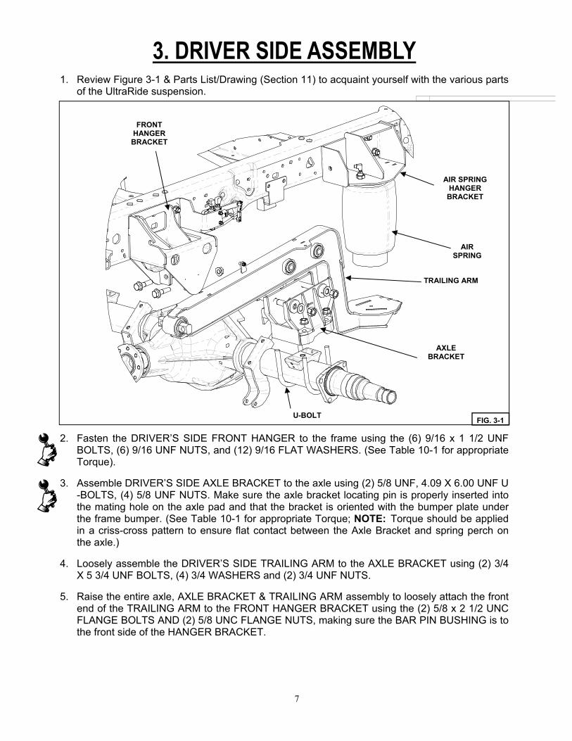
1. Review Figure 3-1 & Parts List/Drawing (Section 11) to acquaint yourself with the various parts of the UltraRide suspension.
2. Fasten the DRIVER’S SIDE FRONT HANGER to the frame using the (6) 9/16 x 1 1/2 UNF BOLTS, (6) 9/16 UNF NUTS, and (12) 9/16 FLAT WASHERS. (See Table 10-1 for appropriate Torque).
3. Assemble DRIVER’S SIDE AXLE BRACKET to the axle using (2) 5/8 UNF, 4.09 X 6.00 UNF U-BOLTS, (4) 5/8 UNF NUTS. Make sure the axle bracket locating pin is properly inserted into the mating hole on the axle pad and that the bracket is oriented with the bumper plate under the frame bumper. (See Table 10-1 for appropriate Torque; NOTE: Torque should be applied in a criss-cross pattern to ensure flat contact between the Axle Bracket and spring perch on the axle.)
4. Loosely assemble the DRIVER’S SIDE TRAILING ARM to the AXLE BRACKET using (2) 3/4 X 5 3/4 UNF BOLTS, (4) 3/4 WASHERS and (2) 3/4 UNF NUTS.
5. Raise the entire axle, AXLE BRACKET & TRAILING ARM assembly to loosely attach the front end of the TRAILING ARM to the FRONT HANGER BRACKET using the (2) 5/8 x 2 1/2 UNC FLANGE BOLTS AND (2) 5/8 UNC FLANGE NUTS, making sure the BAR PIN BUSHING is to the front side of the HANGER BRACKET.
FRONT HANGER
BRACKET
AIR SPRING HANGER
BRACKET
AIR SPRING
TRAILING ARM
AXLE BRACKET
U-BOLT FIG. 3-1
7
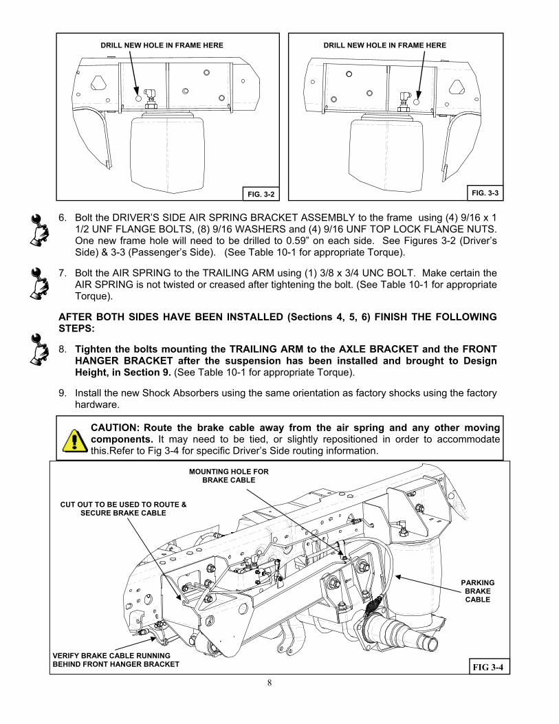
6. Bolt the DRIVER’S SIDE AIR SPRING BRACKET ASSEMBLY to the frame using (4) 9/16 x 1 1/2 UNF FLANGE BOLTS, (8) 9/16 WASHERS and (4) 9/16 UNF TOP LOCK FLANGE NUTS. One new frame hole will need to be drilled to 0.59” on each side. See Figures 3-2 (Driver’s Side) & 3-3 (Passenger’s Side). (See Table 10-1 for appropriate Torque).
7. Bolt the AIR SPRING to the TRAILING ARM using (1) 3/8 x 3/4 UNC BOLT. Make certain the AIR SPRING is not twisted or creased after tightening the bolt. (See Table 10-1 for appropriate Torque).
AFTER BOTH SIDES HAVE BEEN INSTALLED (Sections 4, 5, 6) FINISH THE FOLLOWING STEPS:
8. Tighten the bolts mounting the TRAILING ARM to the AXLE BRACKET and the FRONT HANGER BRACKET after the suspension has been installed and brought to Design Height, in Section 9. (See Table 10-1 for appropriate Torque).
9. Install the new Shock Absorbers using the same orientation as factory shocks using the factory hardware.
FIG. 3-3
DRILL NEW HOLE IN FRAME HERE
FIG. 3-2
DRILL NEW HOLE IN FRAME HERE
CAUTION: Route the brake cable away from the air spring and any other moving components. It may need to be tied, or slightly repositioned in order to accommodate this.Refer to Fig 3-4 for specific Driver’s Side routing information.
8
PARKING BRAKE CABLE
MOUNTING HOLE FOR BRAKE CABLE
CUT OUT TO BE USED TO ROUTE & SECURE BRAKE CABLE
VERIFY BRAKE CABLE RUNNING BEHIND FRONT HANGER BRACKET FIG 3-4
4. PASSENGER SIDE DISASSEMBLY
1. Repeat Section 2 for the passenger side of the truck.
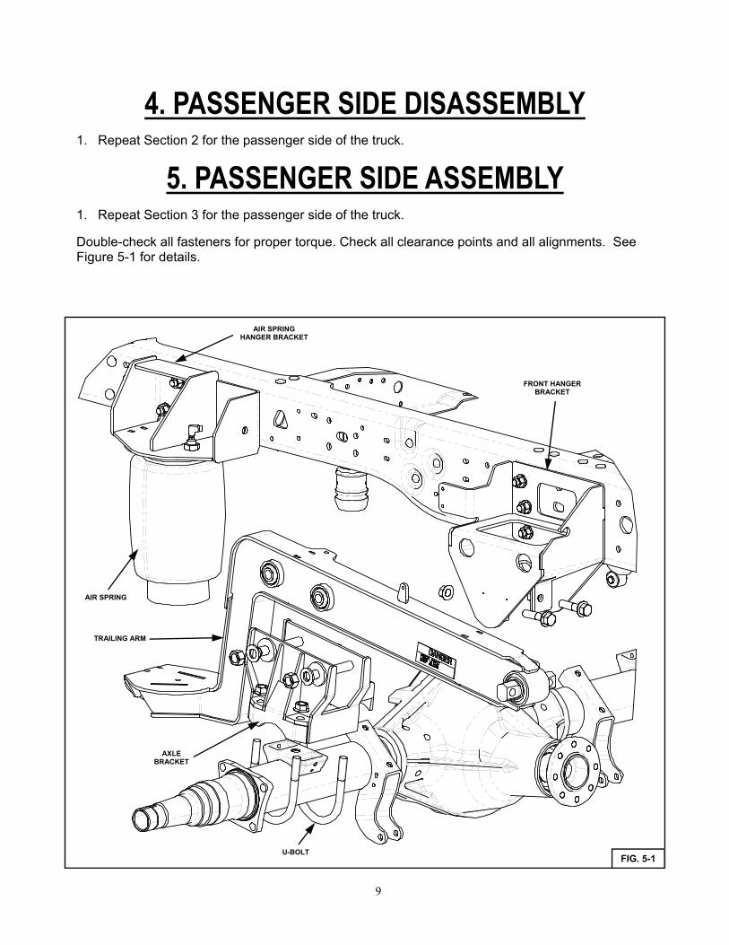
5. PASSENGER SIDE ASSEMBLY
1. Repeat Section 3 for the passenger side of the truck.
Double-check all fasteners for proper torque. Check all clearance points and all alignments. See Figure 5-1 for details.
U-BOLT
AIR SPRING HANGER BRACKET
FRONT HANGER BRACKET
TRAILING ARM
AIR SPRING
FIG. 5-1
AXLE BRACKET
9
6. LATERAL CONTROL ROD
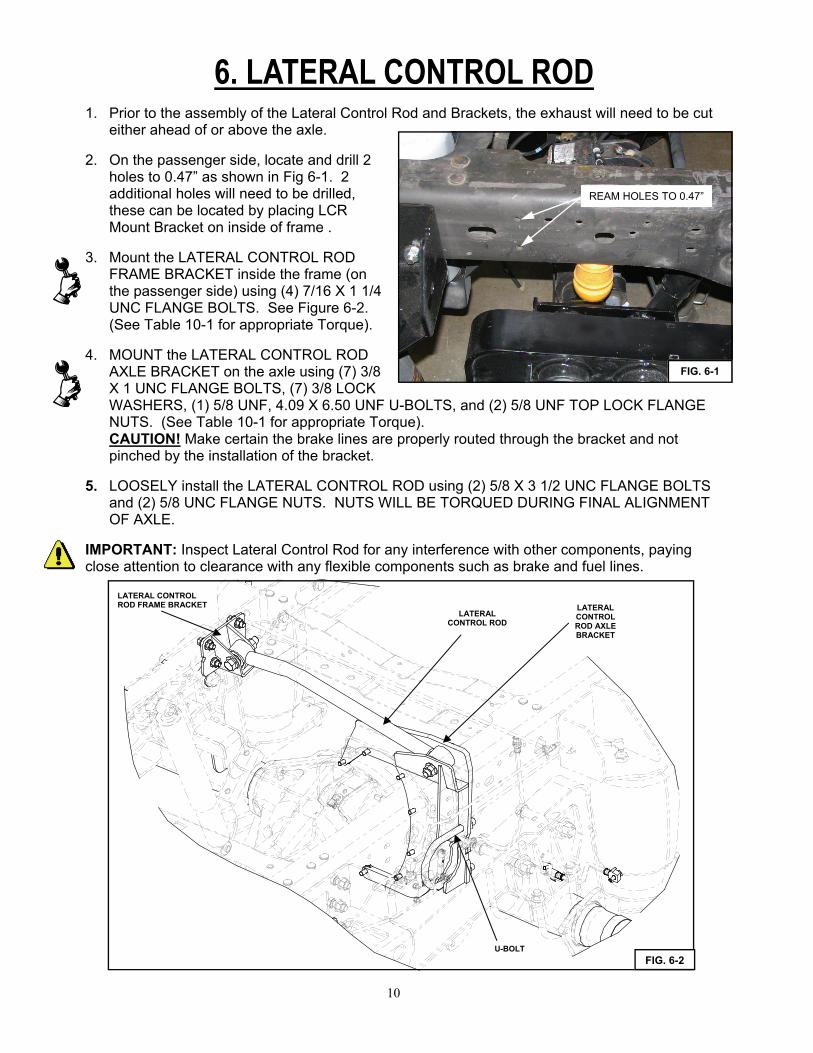
1. Prior to the assembly of the Lateral Control Rod and Brackets, the exhaust will need to be cut either ahead of or above the axle.
2. On the passenger side, locate and drill 2 holes to 0.47” as shown in Fig 6-1. 2 additional holes will need to be drilled, these can be located by placing LCR Mount Bracket on inside of frame .
3. Mount the LATERAL CONTROL ROD FRAME BRACKET inside the frame (on the passenger side) using (4) 7/16 X 1 1/4 UNC FLANGE BOLTS. See Figure 6-2. (See Table 10-1 for appropriate Torque).
4. MOUNT the LATERAL CONTROL ROD AXLE BRACKET on the axle using (7) 3/8 X 1 UNC FLANGE BOLTS, (7) 3/8 LOCK WASHERS, (1) 5/8 UNF, 4.09 X 6.50 UNF U-BOLTS, and (2) 5/8 UNF TOP LOCK FLANGE NUTS. (See Table 10-1 for appropriate Torque). CAUTION! Make certain the brake lines are properly routed through the bracket and not pinched by the installation of the bracket.
5. LOOSELY install the LATERAL CONTROL ROD using (2) 5/8 X 3 1/2 UNC FLANGE BOLTS and (2) 5/8 UNC FLANGE NUTS. NUTS WILL BE TORQUED DURING FINAL ALIGNMENT OF AXLE.
IMPORTANT: Inspect Lateral Control Rod for any interference with other components, paying close attention to clearance with any flexible components such as brake and fuel lines.
FIG. 6-1
REAM HOLES TO 0.47”
FIG. 6-2
LATERAL CONTROL ROD AXLE BRACKET
LATERAL CONTROL ROD
LATERAL CONTROL ROD FRAME BRACKET
U-BOLT
10
7. AIR CONTROL SYSTEM ASSEMBLY
Note: If your vehicle has a frame body that does not allow the air control system box to be located as shown, you will need to determine another location for mounting and drill the necessary holes. If installing on the frame underneath the cab, make sure it is mounted as high on the frame as possible to allow for ground clearance below the tank.
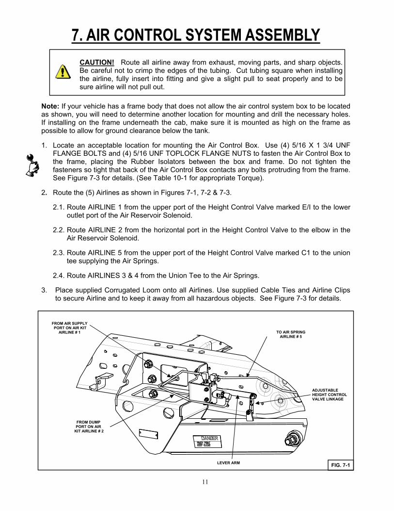
1. Locate an acceptable location for mounting the Air Control Box. Use (4) 5/16 X 1 3/4 UNF FLANGE BOLTS and (4) 5/16 UNF TOPLOCK FLANGE NUTS to fasten the Air Control Box to the frame, placing the Rubber Isolators between the box and frame. Do not tighten the fasteners so tight that back of the Air Control Box contacts any bolts protruding from the frame. See Figure 7-3 for details. (See Table 10-1 for appropriate Torque).
2. Route the (5) Airlines as shown in Figures 7-1, 7-2 & 7-3.
2.1. Route AIRLINE 1 from the upper port of the Height Control Valve marked E/I to the lower outlet port of the Air Reservoir Solenoid.
2.2. Route AIRLINE 2 from the horizontal port in the Height Control Valve to the elbow in the Air Reservoir Solenoid.
2.3. Route AIRLINE 5 from the upper port of the Height Control Valve marked C1 to the union tee supplying the Air Springs.
2.4. Route AIRLINES 3 & 4 from the Union Tee to the Air Springs.
3. Place supplied Corrugated Loom onto all Airlines. Use supplied Cable Ties and Airline Clips to secure Airline and to keep it away from all hazardous objects. See Figure 7-3 for details.
CAUTION! Route all airline away from exhaust, moving parts, and sharp objects. Be careful not to crimp the edges of the tubing. Cut tubing square when installing the airline, fully insert into fitting and give a slight pull to seat properly and to be sure airline will not pull out.
TO AIR SPRING AIRLINE # 5
FROM DUMP PORT ON AIR
KIT AIRLINE # 2
FROM AIR SUPPLY PORT ON AIR KIT
AIRLINE # 1
ADJUSTABLE HEIGHT CONTROL VALVE LINKAGE
LEVER ARM FIG. 7-1
11
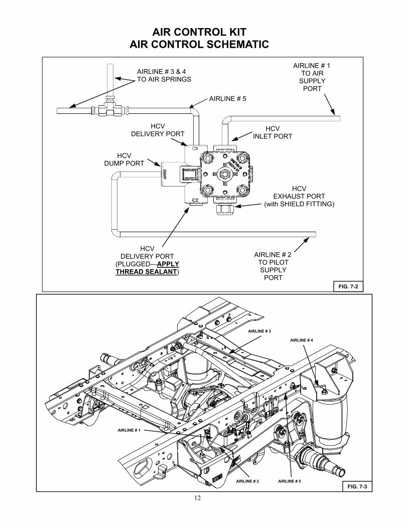
AIR CONTROL KIT AIR CONTROL SCHEMATIC
AIRLINE # 3 & 4 TO AIR SPRINGS
AIRLINE # 2 TO PILOT SUPPLY
PORT
AIRLINE # 1 TO AIR
SUPPLY PORT
FIG. 7-2
HCV INLET PORT
HCV DELIVERY PORT
HCV EXHAUST PORT
(with SHIELD FITTING)
HCV DELIVERY PORT
(PLUGGED—APPLY THREAD SEALANT)
HCV DUMP PORT
AIRLINE # 5
12
AIRLINE # 1
AIRLINE # 2
AIRLINE # 4
AIRLINE # 3
AIRLINE # 5
FIG. 7-3
8. ELECTRICAL SYSTEM
Refer to AIR CONTROL SYSTEM INSTALLATION INSTRUCTIONS for further details on electrical system installation and parts list.
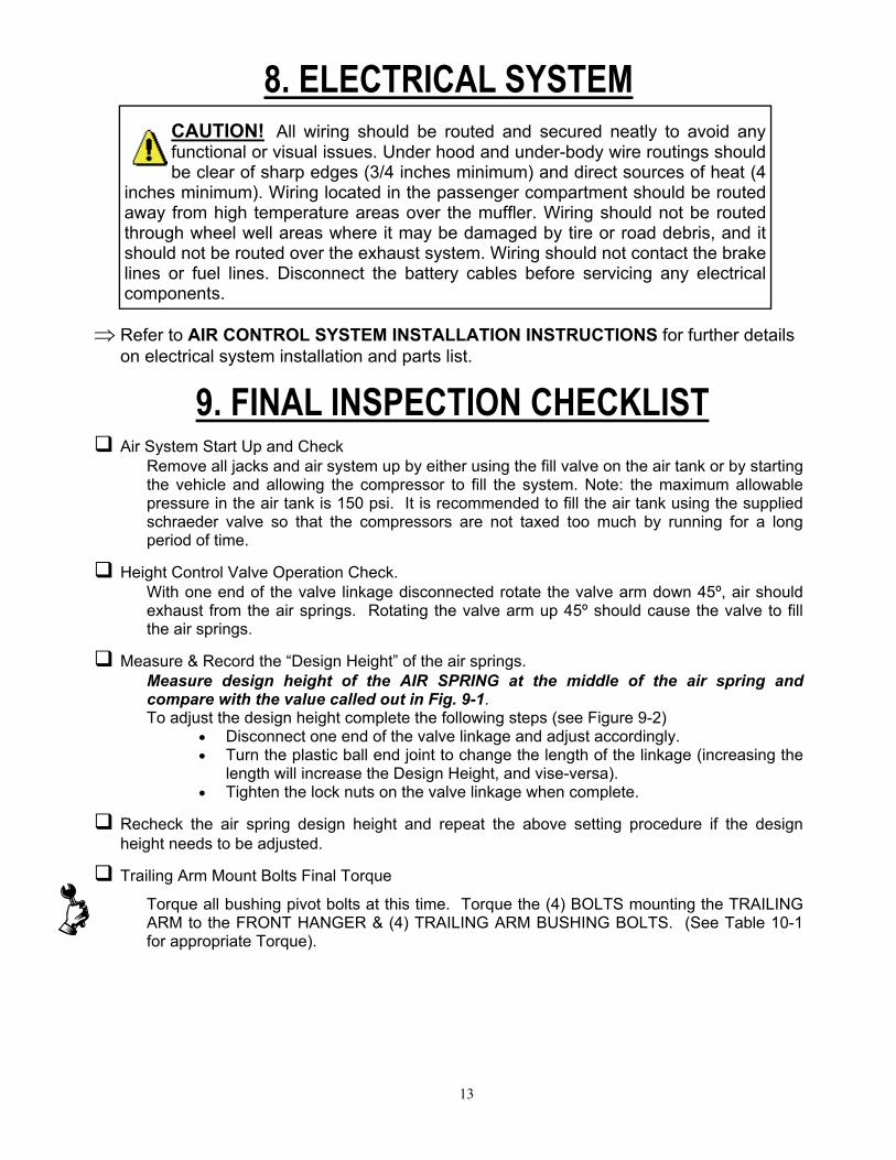
CAUTION! All wiring should be routed and secured neatly to avoid any functional or visual issues. Under hood and under-body wire routings should be clear of sharp edges (3/4 inches minimum) and direct sources of heat (4
inches minimum). Wiring located in the passenger compartment should be routed away from high temperature areas over the muffler. Wiring should not be routed through wheel well areas where it may be damaged by tire or road debris, and it should not be routed over the exhaust system. Wiring should not contact the brake lines or fuel lines. Disconnect the battery cables before servicing any electrical components.
9. FINAL INSPECTION CHECKLIST
Air System Start Up and Check Remove all jacks and air system up by either using the fill valve on the air tank or by starting the vehicle and allowing the compressor to fill the system. Note: the maximum allowable pressure in the air tank is 150 psi. It is recommended to fill the air tank using the supplied schraeder valve so that the compressors are not taxed too much by running for a long period of time.
Height Control Valve Operation Check. With one end of the valve linkage disconnected rotate the valve arm down 45º, air should exhaust from the air springs. Rotating the valve arm up 45º should cause the valve to fill the air springs.
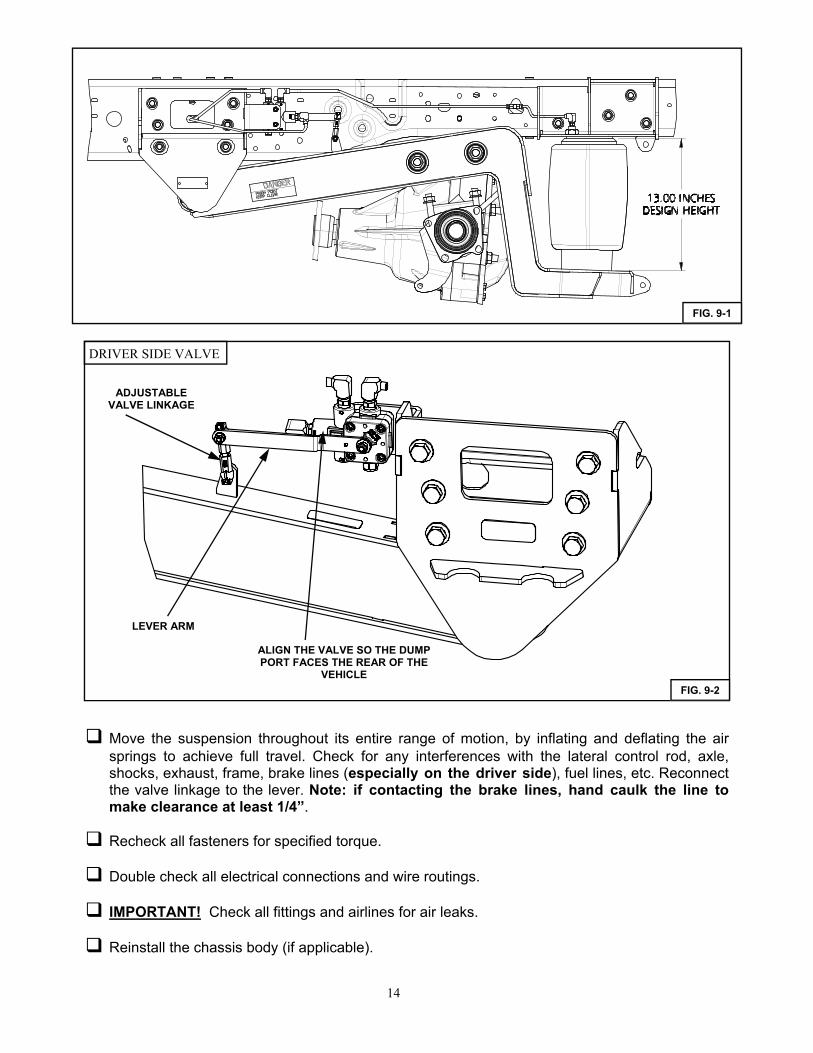
Measure & Record the “Design Height” of the air springs. Measure design height of the AIR SPRING at the middle of the air spring and compare with the value called out in Fig. 9-1. To adjust the design height complete the following steps (see Figure 9-2)
Disconnect one end of the valve linkage and adjust accordingly. Turn the plastic ball end joint to change the length of the linkage (increasing the
length will increase the Design Height, and vise-versa). Tighten the lock nuts on the valve linkage when complete.
Recheck the air spring design height and repeat the above setting procedure if the design height needs to be adjusted.
Trailing Arm Mount Bolts Final Torque
Torque all bushing pivot bolts at this time. Torque the (4) BOLTS mounting the TRAILING ARM to the FRONT HANGER & (4) TRAILING ARM BUSHING BOLTS. (See Table 10-1 for appropriate Torque).
13
Move the suspension throughout its entire range of motion, by inflating and deflating the air springs to achieve full travel. Check for any interferences with the lateral control rod, axle, shocks, exhaust, frame, brake lines (especially on the driver side), fuel lines, etc. Reconnect the valve linkage to the lever. Note: if contacting the brake lines, hand caulk the line to make clearance at least 1/4”.
Recheck all fasteners for specified torque.
Double check all electrical connections and wire routings.
IMPORTANT! Check all fittings and airlines for air leaks.
Reinstall the chassis body (if applicable).
FIG. 9-1
FIG. 9-2
LEVER ARM
ADJUSTABLE VALVE LINKAGE
ALIGN THE VALVE SO THE DUMP PORT FACES THE REAR OF THE
VEHICLE
DRIVER SIDE VALVE
14
10. OPERATION GUIDELINES
After all final checks are complete, it is recommended to complete a full four- wheel alignment and drive line angle check. The pages following the installation instructions describe the proper method for checking driveline angles. Note: improper driveline angles may have a detrimental effect on ride, u-joints, and transmission. If any driveline vibration (or out of spec. angle meas-urement) occurs, use factory axle seat shims to modify driveline angle.
IMPORTANT! During servicing check tightness of all fasteners and for any air system leaks.
IMPORTANT! Immediate corrective action should be taken if malfunctions occur.
Air Spring Design Height Setting Procedure for Systems with Dual Height Control Valves
1. Deflate the passenger side air bag by disconnecting the linkage from the arm. 2. With the driver side linkage connected, measure the design height and adjust accord-
ingly by the methods mentioned above, 3. Once the design height is set for the driver side, repeat the same steps for the passen-
ger side, including deflating the driver side air bag. 4. Once the design height is set, reconnect the linkages. 5. Jostle the suspension up and down and then allow it to come back to design height.
Recheck the initial measurement and adjust if needed. Note: this procedure to set design height can be done when empty or under light load.
15
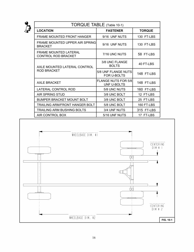
TORQUE TABLE (Table 10-1)
LOCATION FASTENER TORQUE
FRAME MOUNTED FRONT HANGER 9/16 UNF NUTS 130 FT-LBS
FRAME MOUNTED UPPER AIR SPRING BRACKET
9/16 UNF NUTS 130 FT-LBS
FRAME MOUNTED LATERAL CONTROL ROD BRACKET
7/16 UNC NUTS 58 FT-LBS
3/8 UNC FLANGE BOLTS
40 FT-LBS
5/8 UNF FLANGE NUTS FOR U-BOLTS 148 FT-LBS
AXLE BRACKET FLANGE NUTS FOR 5/8
UNF U-BOLTS 148 FT-LBS
LATERAL CONTROL ROD 5/8 UNC NUTS 160 FT-LBS
AIR SPRING STUD 3/8 UNC BOLT 12 FT-LBS
BUMPER BRACKET MOUNT BOLT 3/8 UNC BOLT 25 FT-LBS
TRAILING ARM/FRONT HANGER BOLT 5/8 UNC BOLT 160 FT-LBS
TRAILING ARM BUSHING BOLTS 3/4 UNF NUTS 315 FT-LBS
AIR CONTROL BOX 5/16 UNF NUTS 17 FT-LBS
AXLE MOUNTED LATERAL CONTROL ROD BRACKET
FIG. 10-1
16
11. SERVICE & MAINTENANCE
The UltraRide suspension needs no lubrication and little maintenance. The following components should be checked at the time the truck is being serviced. However, immediate corrective action should be taken if a serious malfunction occurs. See Exploded Assembly on following page for de-tails.
Note: It is important to release any moisture contained within the air reservoir on a daily basis. This can be done by pulling on the cable attached to the drain valve. See Figure 8-1. Not releasing the moisture on a regular basis will cause the drain valve to operate improperly, and may cause the valve to malfunction. Excess moisture in the system can also cause premature failure of other components including the tank itself.
CAUTION! If maintenance or service is to be done on the air system, be sure to drain all air from system. Serious injury could occur if components are removed while system is full of air.
INSTALLATION & MAINTENANCE CHECK LIST Once all fasteners are properly torqued, paint scribe each fastener as a method to
assure the torque procedure has been followed and to allow for a visual check during vehicle servicing intervals.
Check and document OE rear axle alignment
Verify Air Spring Design Height is set at 13.0 inches
Verify suspension function via dump and reinflation
Check for air leaks and system integrity
Check clearances throughout suspension motion range
Check driveline angle
4 wheel alignment
Measure and record wheelbase and centering dims below.
17
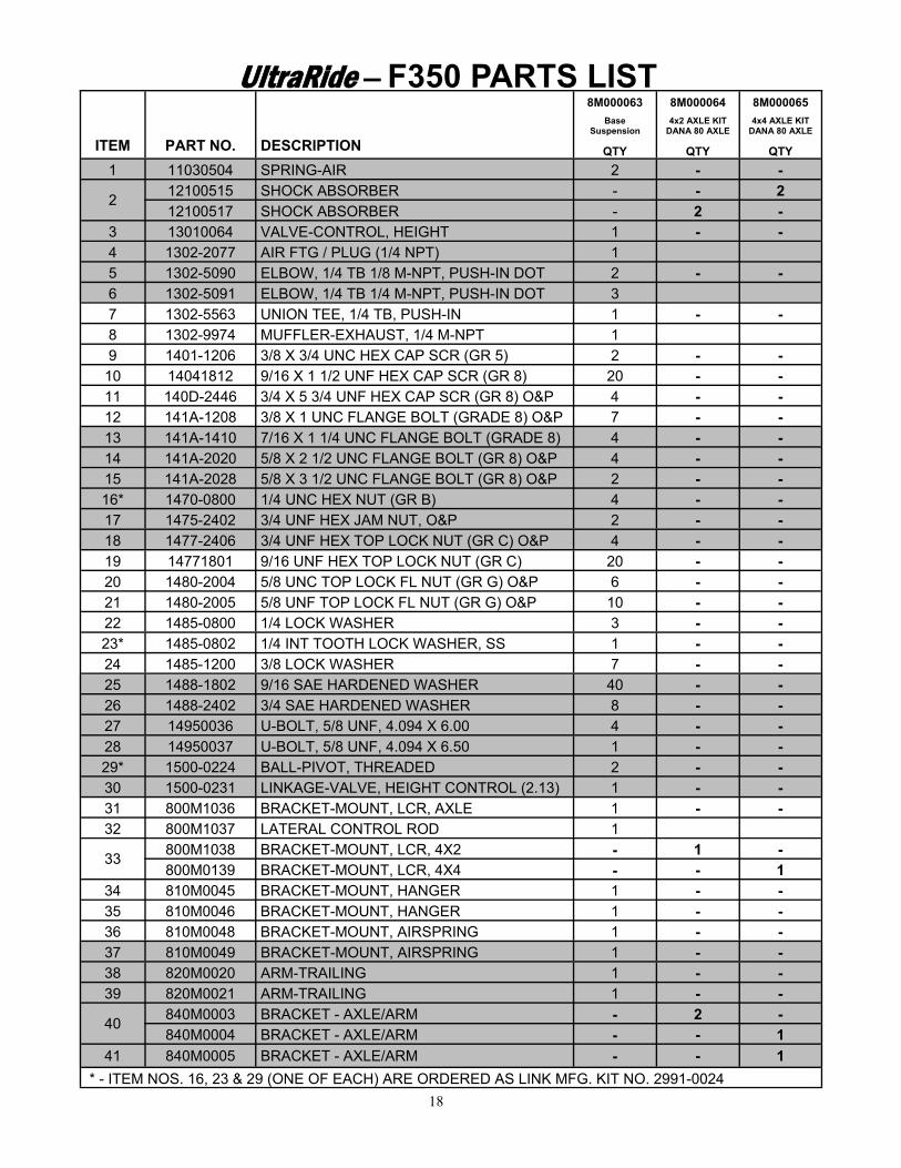
UltraRide — F350 PARTS LIST
ITEM PART NO. DESCRIPTION
8M000063 8M000064 8M000065
Base Suspension
4x2 AXLE KIT DANA 80 AXLE
4x4 AXLE KIT DANA 80 AXLE
QTY QTY QTY
1 11030504 SPRING-AIR 2 - -
2 12100515 SHOCK ABSORBER - - 2 12100517 SHOCK ABSORBER - 2 -
3 13010064 VALVE-CONTROL, HEIGHT 1 - - 4 1302-2077 AIR FTG / PLUG (1/4 NPT) 1 5 1302-5090 ELBOW, 1/4 TB 1/8 M-NPT, PUSH-IN DOT 2 - - 6 1302-5091 ELBOW, 1/4 TB 1/4 M-NPT, PUSH-IN DOT 3 7 1302-5563 UNION TEE, 1/4 TB, PUSH-IN 1 - -
9 1401-1206 3/8 X 3/4 UNC HEX CAP SCR (GR 5) 2 - - 10 14041812 9/16 X 1 1/2 UNF HEX CAP SCR (GR 8) 20 - - 11 140D-2446 3/4 X 5 3/4 UNF HEX CAP SCR (GR 8) O&P 4 - - 12 141A-1208 3/8 X 1 UNC FLANGE BOLT (GRADE 8) O&P 7 - - 13 141A-1410 7/16 X 1 1/4 UNC FLANGE BOLT (GRADE 8) 4 - - 14 141A-2020 5/8 X 2 1/2 UNC FLANGE BOLT (GR 8) O&P 4 - - 15 141A-2028 5/8 X 3 1/2 UNC FLANGE BOLT (GR 8) O&P 2 - - 16* 1470-0800 1/4 UNC HEX NUT (GR B) 4 - - 17 1475-2402 3/4 UNF HEX JAM NUT, O&P 2 - - 18 1477-2406 3/4 UNF HEX TOP LOCK NUT (GR C) O&P 4 - - 19 14771801 9/16 UNF HEX TOP LOCK NUT (GR C) 20 - - 20 1480-2004 5/8 UNC TOP LOCK FL NUT (GR G) O&P 6 - - 21 1480-2005 5/8 UNF TOP LOCK FL NUT (GR G) O&P 10 - - 22 1485-0800 1/4 LOCK WASHER 3 - - 23* 1485-0802 1/4 INT TOOTH LOCK WASHER, SS 1 - - 24 1485-1200 3/8 LOCK WASHER 7 - - 25 1488-1802 9/16 SAE HARDENED WASHER 40 - - 26 1488-2402 3/4 SAE HARDENED WASHER 8 - - 27 14950036 U-BOLT, 5/8 UNF, 4.094 X 6.00 4 - - 28 14950037 U-BOLT, 5/8 UNF, 4.094 X 6.50 1 - - 29* 1500-0224 BALL-PIVOT, THREADED 2 - - 30 1500-0231 LINKAGE-VALVE, HEIGHT CONTROL (2.13) 1 - - 31 800M1036 BRACKET-MOUNT, LCR, AXLE 1 - - 32 800M1037 LATERAL CONTROL ROD 1
33 800M1038 BRACKET-MOUNT, LCR, 4X2 - 1 - 800M0139 BRACKET-MOUNT, LCR, 4X4 - - 1
34 810M0045 BRACKET-MOUNT, HANGER 1 - - 35 810M0046 BRACKET-MOUNT, HANGER 1 - - 36 810M0048 BRACKET-MOUNT, AIRSPRING 1 - - 37 810M0049 BRACKET-MOUNT, AIRSPRING 1 - - 38 820M0020 ARM-TRAILING 1 - - 39 820M0021 ARM-TRAILING 1 - -
40 840M0003 BRACKET - AXLE/ARM - 2 - 840M0004 BRACKET - AXLE/ARM - - 1
41 840M0005 BRACKET - AXLE/ARM - - 1
* - ITEM NOS. 16, 23 & 29 (ONE OF EACH) ARE ORDERED AS LINK MFG. KIT NO. 2991-0024
8 1302-9974 MUFFLER-EXHAUST, 1/4 M-NPT 1
18
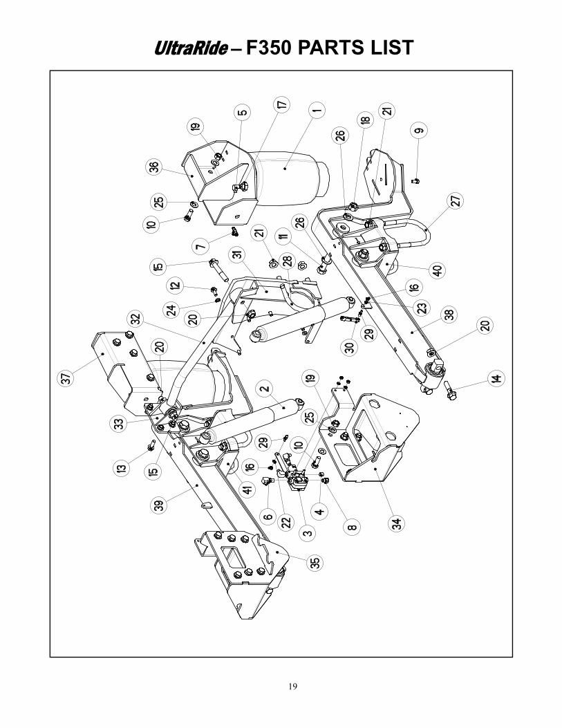
UltraRide — F350 PARTS LIST
19

COMPONENT POSSIBLE PROBLEM CORRECTIVE ACTION
Airlines Air leaks Replace airline
Fittings Air leaks Remove fitting and apply fresh joint compound. Reinstall fitting, but Do Not Over tighten. Do not use Teflon tape.
Air Springs A. Improper height
B. Air leakage
A. Adjust valve linkage to maintain proper air spring height.
B. Replace air spring.
Height Control Valve* Air spring(s) will not inflate when weight is added to the chassis.
OR
Air spring(s) will not deflate when weight is removed from the chassis.
A. Inspect valves to insure alignment indicator is located correctly. The alignment indicator should be aligned with the exhaust port of the valve. If not, loosen lever nut (but do not re-move completely) and pull lever loose from drive bearing, rotate drive bearing until the alignment indicator is in the correct position and re-secure lever by tightening lever nut.
See Fig. 9-2 for orientation details
B. Replace valve.
Shock Absorber Insufficient damping effect Replace shocks
Lateral Control Rod A. Loose nuts on lateral control rod bolts
B. Worn bushings
A. Tighten securely.
B. Replace lateral control rod.
UltraRide - TROUBLE SHOOTING GUIDE
20
FORD F350 OWNERS GUIDELINES
The UltraRide suspension needs no lubrication and little maintenance. However, immediate cor-rective action should be taken if a serious malfunction occurs.
PRODUCT OWNER RESPONSIBILITIES Owner is solely responsible for pre-operation inspection, periodic inspections, maintenance,
and use of the product as specified in the particular LINK MFG. instructions available by prod-uct model, except as provided in this warranty, and for maintenance of other vehicle compo-nents. Of particular importance is the re-torque of fasteners including axle u-bolts, torque rod bolts and track rod bolts. This re-torque must be performed within 90 days of the suspension being put in service.
Owner is responsible for “down time” expenses, cargo damage, and all business costs and losses resulting from a warrantable failure.
The UltraRide Chassis Air Suspension is fully automatic in controlling the height of the chassis. No manual intervention to control air pressure or ride height is needed during the course of op-eration.
The Low Pressure Warning Light indicates a severe drop in tank pressure (below 60 psi). If the light stays on for a significant period of time, corrective action should be taken to determine the cause of air loss or system malfunction. NOTE: The Low Pressure Warning Light could come on briefly when the “Dump” feature is being used.
It is important to release any moisture contained within the air tank on a daily basis. This is done by pulling on the attached release cable for approximately 5 seconds. See Air Control Kit Owners Manual for location of this cable. Not releasing the moisture on a regular basis will cause the drain valve to not operate properly.
CHECK AT EVERY VEHICLE SERVICE INTERVAL:
Check Design Height ±¼”. Check for air leaks around fittings.
CHECK AFTER THE FIRST 1000 MILES:
Recheck & tighten any loose fasteners. Check for any loose or worn components.
CHECK AFTER EVERY 30,000 MILES:
Check arm pivot bushings and lateral control rod bushings for wear; replace if worn
CAUTION! If maintenance or service is to be done on the air system, be sure to drain all air from the system. Serious injury could occur if components are removed while system is full of air.
21
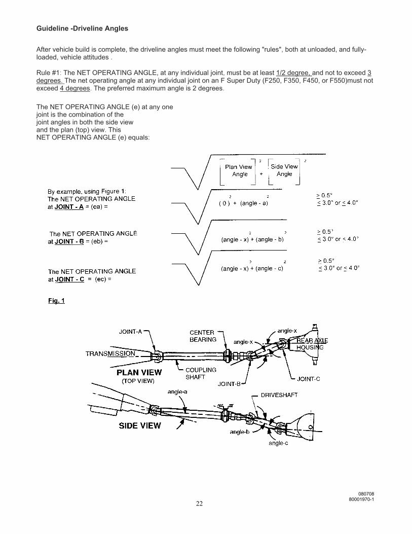
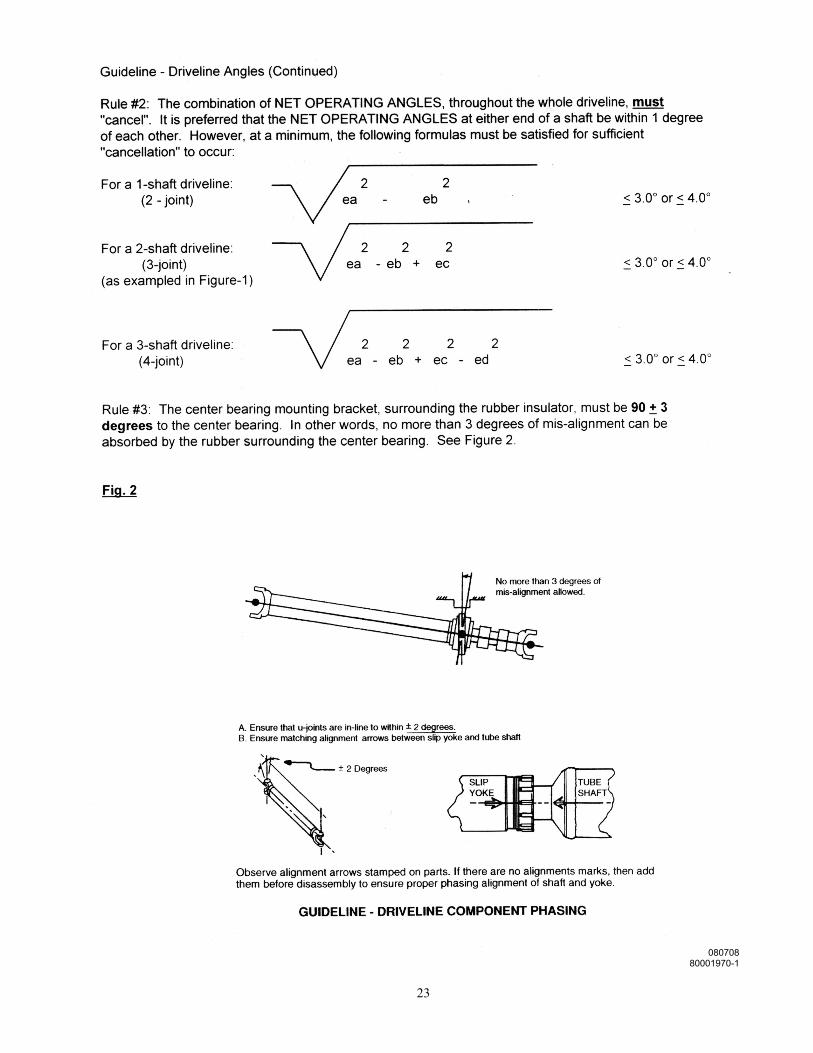
Guideline -Driveline Angles
After vehicle build is complete, the driveline angles must meet the following "rules", both at unloaded, and fully-loaded, vehicle attitudes . Rule #1: The NET OPERATING ANGLE, at any individual joint, must be at least 1/2 degree, and not to exceed 3 degrees. The net operating angle at any individual joint on an F Super Duty (F250, F350, F450, or F550)must not exceed 4 degrees. The preferred maximum angle is 2 degrees.
The NET OPERATING ANGLE (e) at any one joint is the combination of the joint angles in both the side view and the plan (top) view. This NET OPERATING ANGLE (e) equals:
080708 80001970-1
22
080708 80001970-1
23
Link Mfg. Ltd. 223 15th St. NE
Sioux Center, IA USA 51250-2120
(712) 722-4874
http://www.linkmfg.com/
MINIMUM UNIVERSAL JOINT OPERATING ANGLE: A slight angle is required to prevent universal joints from brinelling. Therefore, a minimum operating an-gle of 1/2 degree is required. MAXIMUM UNIVERSAL JOINT OPERATING ANGLE: Universal joint operating angles can be quite high, sometimes as high as 12 degrees. But to get a vehi-cle to operate successfully above 3 degrees often requires larger universal joints, double cardan or constant ve-locity joints, or restrictions on operating speed. A reduction in universal joint life becomes noticeable when they are operated at more than 3 degrees if precautions are not taken. That having been stated, the F Super Duty series of trucks can tolerate angles up to 4 degrees. However, maximum angles of 2 degrees are preferable for all vehicles. Two shafts connected with a single cardan joint and turning at a constant speed with no joint angle, have. no angular acceleration that could cause a vibration. When there is an angle between them and the input shaft is turning at a constant speed, the driven shaft is forced to continuously accelerate and decelerate, twice per revolution , creating a vibration . If the speed changes are small, the vibration is not objectionable. The guidelines in this appendix limit driveline angular acceleration to a maximum of 400 radians per second per sec-ond. This is the requirement for all Ford light trucks. (SAE specifies 500.) Some modified drivelines have been measured at over 11,000 radians per second per second causing driveline failures at very low mileage. DRIVELINE ANGLE MEASUREMENT: Driveline angle measurements should be made with the vehicle supported by the tires and resting on a level surface . Avoid hoisting a vehicle by the frame since this will distort the chassis enough to make any meas-urements inaccurate. MATCH MOUNTING DRIVESHAFTS TO THE REAR AXLE: Runout is measured on OEM rear axle input shafts and the maximum measurement is shown with a dot or other marking on the yoke or pilot bearing flange. The OEM driveshafts may also be marked with indicative marking on the "light" side. When the parts are assembled , the marks are aligned to aid the overall system balance. Vehicle modifiers should look for these alignment marks and maintain this match when the drivetrain is reassembled after modification. Remanufactured or modified driveshafts should also have their "light" sides matched to the mark on the yoke or pilot bearing flange. DRIVELINE VIBRATION DAMPERS: Driveline vibration dampers are sometimes added to driveshafts or axles to reduce noise, vibration, and harshness (NVH). If the chassis has these devices when it is received , they should be retained on the modified chassis. USE OF DOUBLE CARDAN UNIVERSAL JOINTS FOR GREATER DRIVE ANGLES: In general , the use of these joints can allow increased drive angles up to as much as 8 degrees. How-ever, when used at the rear of a coupling shaft a double cardan universal joint will prevent cancellation from oc-curring at the forward end of the shaft. Therefore the single cardan joint must still be maintained at less than 3 degrees (or 4 degees for the F Super Duty series). GENERAL COMMENTS: It is good practice, for any chassis that will have a driveline modification, to measure and record the driveline angles in each of the following conditions for later comparison. A. The chassis as first received from Ford (note that the drive angles may not conform exactly to this bulle tin in this incomplete condition). B. The completed vehicle, unloaded. C. The completed vehicle loaded to GVWR with maximum front GAWR. D. The completed vehicle loaded to GVWR with maximum rear GAWR.
080708 80001970-1
24