foreword - praslinpraslin.com.ua/files/pr5200 soft starter manual.pdf · thanks for selecting...
TRANSCRIPT

Foreword
Thank you very much for purchasing PR5200 soft starter.
This User’s Manual provides the users with the instructions on the installation, parameter
setting, error diagnosis, remote control software instruction, routine maintenance and necessary
precautions. Please read the Manual carefully before the installation of the product in order to
ensure that it can be correctly installed and operated.
Please contact Powtran's dealers or directly contact with the company if you have difficult
questions during the use of the soft starter , our professional staff is willing to serve for you.
Please leave this manual to the end user and keep it in good condition for the future
maintenance and other application occasions . Please fill in the warranty card then fax to the
distributor or fax to Powtran if there is quality problem during the warranty period.
During this product updating period, some details may be changed without prior notice. If you
want to get the latest information, please visit our website.
For other products’ information, Please visit our homepage:http://www.powtran.com.
Contents
Precaution .............................................................................................................. 4
Section I The introduction of PR5200 soft starter ................................................ 1
1-1. The feature of the PR5200 soft starter .......................................... 1
1-2. The main function of the PR5200 soft starter ................................ 1
1-3. The main features of the PR5200 soft starter................................. 1
Section II Product model description and open package inspection ...................... 3 2-1. The steps of open package inspection ........................................... 3
Section III The Conditions of use and installation requirements........................... 4
3-1. The Conditions of use of the soft starter ....................................... 4
3-2. The installation requirements of the soft starter ............................. 4
3-3. The appearance and installation dimension of the soft starter ........ 5
Section IV Main circuit and terminal wiring ....................................................... 7
4-1. The basic wiring diagram of the soft starter .................................. 7
4-2. Instruction of soft starter terminal wiring. ..................................... 8
Section V Control panel and operation ............................................................. 10
5-1 Keyboard operational approach .................................................. 10
5-2 Function parameters setting and description ............................... 12
5-3 Programmable relay output functions ......................................... 13
5-4 Automatic restart function.......................................................... 14
5-5 Other settings Description .......................................................... 15
5-6 .Help and instructions ................................................................ 16
Section Ⅵ Protection and description .................................................................. 17
6-1 Protection functions and their parameters ................................... 17
6-2 Protection level setting description ............................................. 18
Section VII Test runing and application ............................................................ 20
7-1. Power test running ..................................................................... 20
7-2. PR5200 Series soft starter starting mode and application .......... 21
7-3. PR5200 series soft starter's stop mode and application ................ 23
7-4. Special application .................................................................... 24
7-5. Application examples ................................................................ 24
Section VIII RS485 communication ................................................................. 26
Section IX Fault causes and treatment ................................................................... 27
Section X Soft-start model specifications and options ............................................ 29
Section XI Quality Assurance ............................................................................... 30

POWTRAN Technology Product Warranty Card ............................................... - 31 -
Product information feedback ........................................................................... - 34 -
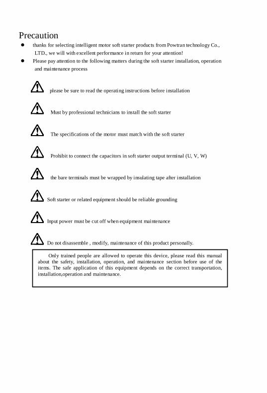
Precaution thanks for selecting intelligent motor soft starter products from Powtran technology Co.,
LTD., we will with excellent performance in return for your attention!
Please pay attention to the following matters during the soft starter installation, operation
and maintenance process
please be sure to read the operating instructions before installation
Must by professional technicians to install the soft starter
The specifications of the motor must match with the soft starter
Prohibit to connect the capacitors in soft starter output terminal (U, V, W)
the bare terminals must be wrapped by insulating tape after installation
Soft starter or related equipment should be reliable grounding
Input power must be cut off when equipment maintenance
Do not disassemble , modify, maintenance of this product personally.
Only trained people are allowed to operate this device, please read this manual
about the safety, installation, operation, and maintenance section before use of the
items. The safe application of this equipment depends on the correct transportation,
installation,operation and maintenance.
1
第
十
章
Sectio
n I
Section I The introduction of PR5200 soft starter
1-1. The feature of the PR5200 soft starter
PR5200 series intelligent motor soft starter incorporates the latest motor control
theory and proprietary motor protection technology and advanced software technology
of new equipment, it is an ideal replacement of startup products which early used start
method of “Star to Triangle conversion”, “autoformer step-down voltage” and
“magnetic control step-down voltage” ; At present market ,Its performance is more
superior than other ordinary soft starter without using intelligent control technology.
1-2. The main function of the PR5200 soft starter
First: to reduce the motor starting current and reduce power distribution capacity,
avoid investment of expansion of power capacity.
The second: to reduce the starting stress of the motor and the load of the
equipment ; Extend lifespan of the motor and related equipments.
Third: Its soft stop function can effectively solve the problem of parking vibration
of the inertial system,which is unable to realize by traditional starting equipment.
Fourth: to have six unique start-up modes adapts to the complex conditions of
motor and load, to perfect start effect.
Fifth: has the perfect and reliable protection function; Effectively protect the
motor and the related production equipment use safety.
Sixth: motor soft starter intelligence, and network technology application makes
motor control technology to adapt to the rapid development of the electric power
automation technology in higher requirements.
1-3. The main features of the PR5200 soft starter
● perfect human nature design:
beautiful shape and reasonable structure
perfect function and easy operation
sturdy and reliable and compact structure
industrial product excellence in the design of art.
● Reliable quality assurance:
using the computer simulation design.
SMT placement production process.
excellent electromagnetism compatibility.
The whole machine of aging, vibration test in high temperature before they
leave the factory
● perfect and reliable protection function:
Voltage lose, lower voltage and over-voltage protection.
soft starter motor overheating, lower load, too long starting time protection.
input phase lose, output phase lose, three-phase unbalance protection.
Startup current, overload, short circuit protection.
Section I The introduction of PR5200 soft starter
2
Sectio
n I
● proprietary intellectual property products:
appearance design patent.
independent software copyright.
proprietary motor starting and protection technology.
unique testing debugging equipment and process.
● swift thoughtful after-sales service:
reliable performance and lay the foundation of quality service quality.
provide excellent perfect supporting design scheme.
timely and thoughtful use consultation.
Continuously improve product performance according to user opinion

3
第
十
章
Sectio
n II
Section II Product model description and open -
package inspection
Each PR5200 series soft starter is under strict inspection and testing before they leave the factory. Users received the products and unpacked, please follow the inspection steps , if found, please contact the supplier promptly
2-1. The steps of open - package inspection Confirm the soft starter without any damage in transport process (machine body
damage or gap). Check with the machine, the instruction manual,the warranty card Check the product of the specifications of the enclosure panels, ensure that the
received goods match with you ordered products
SOURCE:OUTPUT:
TYPE:
Z01001A00001
5.5Kw 11A 3φ 380V 50-60Hz
POWTRAN TECHNOLOGY CO.,LTD.
PR5200 5R5G3Soft starter model
Serial NO.
Output specInput spec
Powtran soft starter
PR 520 0 a 011 G 3
Model specification
Rated Power: 7R5 7.5KW
011 11KW
Class code:0:normal configuration
1:special 1 configuration
2:special 2 configuration
Machine code:
a:General
Function code:
G Gerneral
Output configuration
0:General configuration
4
第
十
章
Sectio
n III
Section III The Conditions of use and installation
requirements
PR5200 series soft starter should comply with the following conditions of use and installation requirements; Otherwise, the performance will not guarantee, it can shorten life of soft starter even damage.
3-1. The Conditions of use of the soft starter
3-1-1. Power supplies: the utility, self-power station, diesel generating sets three-
phase AC 380 V or 660 V plus or minus 15%, frequency 50 Hz or 60 Hz, the
power supply capacity must meet soft starter motor starting to the requirement
3-1-2. Applicable motor: mouse cage type three-phase asynchronous motor,
electrical power rating should with soft starter rated power match.
3-1-3. Start frequency: no demands, depending on the specific number load up.
3-1-4. Cooling way: air cooling.
3-1-5. The protective level: IP20.
3-1-6. Environmental conditions: elevation 3000 meters, the environment
temperature-25 ℃ ~ + 40 ℃ between, relative humidity below 90% RH, no
dewing, no inflammable, no explosive, no corrosive gas easily, have no
electrical conductivity dust, indoor and ventilated good, vibration is less than
0.5 G place.
We can offer under special conditions of use products, such as the explosion
proof type, low temperature, high pressure type type soft starter, its use
conditions will need further instructions.
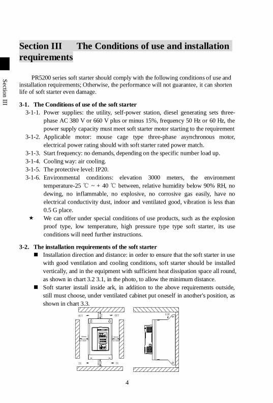
3-2. The installation requirements of the soft starter
Installation direction and distance: in order to ensure that the soft starter in use
with good ventilation and cooling conditions, soft starter should be installed
vertically, and in the equipment with sufficient heat dissipation space all round,
as shown in chart 3.2 3.1, in the photo, to allow the minimum distance.
Soft starter install inside ark, in addition to the above requirements outside,
still must choose, under ventilated cabinet put oneself in another's position, as
shown in chart 3.3.
OUTOUT
IN IN
AIR
50mm 50mm
15
0m
m1
50
mm
Section III The Conditions of use and installation requirements
5
Sectio
n III
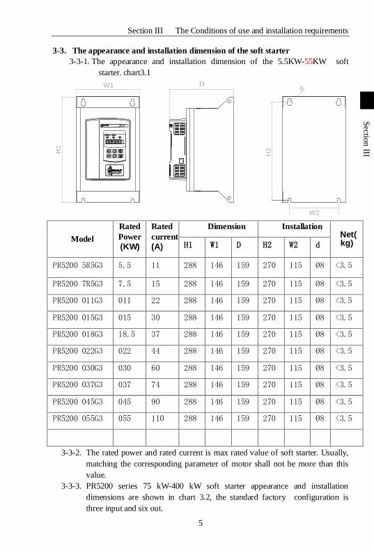
3-3. The appearance and installation dimension of the soft starter
3-3-1. The appearance and installation dimension of the 5.5KW-55KW soft
starter. chart3.1
W1
H1
d
W2
H2
Model
Rated
Power
(KW)
Rated
current
(A)
Dimension Installation Net(kg) H1 W1 D H2 W2 d
PR5200 5R5G3 5.5 11 288 146 159 270 115 Ø8 <3.5
PR5200 7R5G3 7.5 15 288 146 159 270 115 Ø8 <3.5
PR5200 011G3 011 22 288 146 159 270 115 Ø8 <3.5
PR5200 015G3 015 30 288 146 159 270 115 Ø8 <3.5
PR5200 018G3 18.5 37 288 146 159 270 115 Ø8 <3.5
PR5200 022G3 022 44 288 146 159 270 115 Ø8 <3.5
PR5200 030G3 030 60 288 146 159 270 115 Ø8 <3.5
PR5200 037G3 037 74 288 146 159 270 115 Ø8 <3.5
PR5200 045G3 045 90 288 146 159 270 115 Ø8 <3.5
PR5200 055G3 055 110 288 146 159 270 115 Ø8 <3.5
3-3-2. The rated power and rated current is max rated value of soft starter. Usually,
matching the corresponding parameter of motor shall not be more than this
value.
3-3-3. PR5200 series 75 kW-400 kW soft starter appearance and installation
dimensions are shown in chart 3.2, the standard factory configuration is
three input and six out.
Section III The Conditions of use and installation requirements
6
Sectio
n III
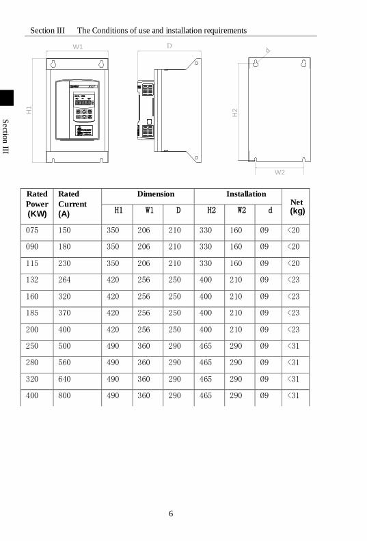
Rated
Power
(KW)
Rated
Current
(A)
Dimension Installation Net (kg) H1 W1 D H2 W2 d
075 150 350 206 210 330 160 Ø9 <20
090 180 350 206 210 330 160 Ø9 <20
115 230 350 206 210 330 160 Ø9 <20
132 264 420 256 250 400 210 Ø9 <23
160 320 420 256 250 400 210 Ø9 <23
185 370 420 256 250 400 210 Ø9 <23
200 400 420 256 250 400 210 Ø9 <23
250 500 490 360 290 465 290 Ø9 <31
280 560 490 360 290 465 290 Ø9 <31
320 640 490 360 290 465 290 Ø9 <31
400 800 490 360 290 465 290 Ø9 <31
W1
H1
d
W2
H2
7
第
十
章
Sectio
n IV
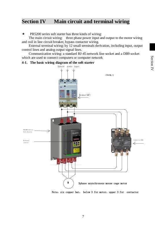
Section IV Main circuit and terminal wiring
PR5200 series soft starter has three kinds of wiring: The main circuit wiring: three phase power input and output to the motor wiring
and coil in line circuit breaker, bypass contactor wiring. External terminal wiring: by 12 small terminals derivation, including input, output
control lines and analog output signal lines. Communication wiring: a standard RJ-45 network line socket and a DB9 socket
which are used to connect computers or computer network
4-1. The basic wiring diagram of the soft starter
PR5200 Series Soft Starter
3phase power input
Keyboard control
M 3phase asynchronous mouse cage motor
Braker(QF)
chart 4.1
Connector(KM)
Note:six copper bar, below 3 for motor,upper 3 for contactor
Section IV Main circuit and terminal wiring
8
Sectio
n IV
7 8 9 10
Transient
stop
stop start common
3lines way
7 8 9 10
Transient
stop
stop start common
2lines way:close K start
open K stop
K
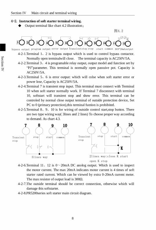
4-2. Instruction of soft starter terminal wiring.
Output terminal like chart 4.2 illustration:
1 2 3 4 5 6 7 8 9 10 11 12
- +
bypass output program output error output Transientstop stop start common DC0~20mAoutput
图4.2
4-2-1.Terminal 1、2 is bypass output which is used to control bypass contactor.
Normally open terminalwill close. The terminal capacity is AC250V/5A.
4-2-2.Terminal 3、4 is programable relay output, output model and function set by
“PJ”parameter. This terminal is normally open passsive pot. Capacity is
AC250V/5A.
4-2-3.Terminal 5、6 is error output: which will colse when soft starter error or
power lose, Capacity is AC250V/5A.
4-2-4.Terminal 7 is transient stop input. This terminal must connect with Terminal
10 when soft starter normally work. If Terminal 7 disconnect with terminal
10, softstart will transient stop and show error. This terminal can be
controled by normal close output terminal of outside protection device, Set
PC to 0 (primary protection),this terminal funtion is prohibited.
4-2-5.Terminal 8、9、10 is for wiring of outside control start,stop button. There
are two type wiring way( 3lines and 2 lines) To choose proper way according
to demand. As chart 4.3.
4-2-6.Terminal 11、12 is 0~20mA DC anolog output. Which is used to inspect
the motor current. The max 20mA indicates motor current is 4 times of soft
starter rated current. Which can be viewed by extra 0-20mA current meter.
The max resistor of output load is 300Ω.
4-2-7.The outside terminal should be correct connection, otherwise which will
damage this softstarter.
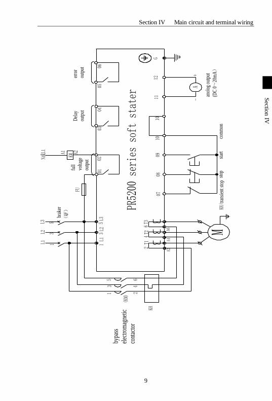
4-2-8.PR5200series soft starter main circuit diagram.
Section IV Main circuit and terminal wiring
9
Sectio
n IV
L1L2
L3
13
5
brak
er
(QF
)
L1L2
L31
35
A2A4
A6
13
5
KH
bypa
ss
elec
trom
agne
tic
cont
acto
r2
46
T1T2
T32
46
0708
0910
1011
12G
0102
0304
0506
M
A-
+
anol
og o
utpu
t
(DC
0~
20m
A)
KH/t
rans
ient
sto
pst
opst
art
com
mon
KMN或L1 A1 A2
full
volta
ge
outp
ut
PR52
00 s
erie
s so
ft s
tate
r
Del
ay
outp
ut
erro
r
outp
utFU
(KM)
10
第
十
章
Sectio
n V
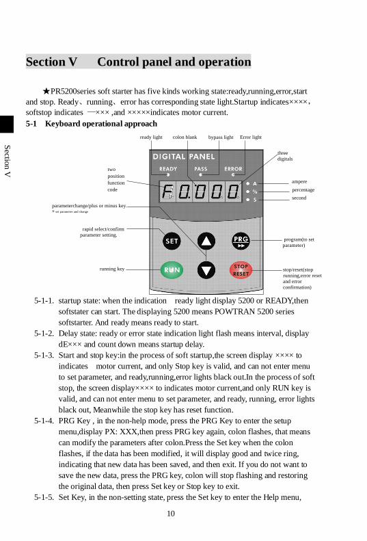
ampere
percentage
second
Error lightbypass lightcolon blankready light
three
digitals
two
position
function
code
parameterchange/plus or minus key.*set parameter and change
program(to set
parameter)
rapid select/confirm
parameter setting.
running key stop/reset(stop
running,error reset
and error
confirmation)
Section V Control panel and operation
★PR5200series soft starter has five kinds working state:ready,running,error,start
and stop. Ready、running、error has corresponding state light.Startup indicates××××,
softstop indicates —××× ,and ×××××indicates motor current.
5-1 Keyboard operational approach
5-1-1. startup state: when the indication ready light display 5200 or READY,then
softstater can start. The displaying 5200 means POWTRAN 5200 series
softstarter. And ready means ready to start.
5-1-2. Delay state: ready or error state indication light flash means interval, display
dE××× and count down means startup delay.
5-1-3. Start and stop key:in the process of soft startup,the screen display ×××× to
indicates motor current, and only Stop key is valid, and can not enter menu
to set parameter, and ready,running,error lights black out.In the process of soft
stop, the screen display×××× to indicates motor current,and only RUN key is
valid, and can not enter menu to set parameter, and ready, running, error lights
black out, Meanwhile the stop key has reset function.
5-1-4. PRG Key , in the non-help mode, press the PRG Key to enter the setup
menu,display PX: XXX,then press PRG key again, colon flashes, that means
can modify the parameters after colon.Press the Set key when the colon
flashes, if the data has been modified, it will display good and twice ring,
indicating that new data has been saved, and then exit. If you do not want to
save the new data, press the PRG key, colon will stop flashing and restoring
the original data, then press Set key or Stop key to exit.
5-1-5. Set Key, in the non-setting state, press the Set key to enter the Help menu,
Section V Control panel and operation
11
Sectio
n V
display HX: XXX, press the Set key or Stop key to exit. In setting state, press
the Set key to save the new setting of data and to exit the setting state.
5-1-6. Acceleration,deceleration key, in the setting menu, when the colon does not
flash ,press the acceleration or deceleration key to change the function number;
when colon flashes, press the acceleration or deceleration key to change the
data, press on the acceleration or deceleration key for more than 1 second, the
data will be increased or decreased continuously and quickly .In the help
menu, press the acceleration or deceleration key to change the function
number and the corresponding message.When the indicator light of bypass
operation is on, and did not enter the setting and help menu, display AXXXX,
that means the motor running current, then press the acceleration or
deceleration key to select display PXXXX or HXXXX.PXXXX indicates
motor apparent power;HXXXX indicates motor overloaded heat balance
coefficient. When indication value of HXXXX is more than 100%,soft starter
will be overload protection and display Err08.
5-1-7. When the data is more than 999, the last decimal point is bright, indicates the
mantissa + 0.
5-1-8. If the key operating is effective,there will be a voice tip, or this key does not
work in this state.
5-1-9. When the external control terminal connected to a 3-wire mode, the external
control start button and stop button have the equivalent function with start and
stop keys on the control panel.
5-1-10. The control panel with super anti-jamming design,and the outside connection
distance is allow to be more than 3 m.
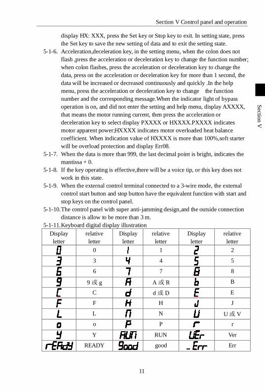
5-1-11. Keyboard digital display illustration
Display
letter
relative
letter
Display
letter
relative
letter
Display
letter
relative
letter
0 1 2
3 4 5
6 7 8
9 或 g A 或 R B
C d 或 D E
F H J
L N U 或 V
o P r
Y RUN Ver
READY good Err
Section V Control panel and operation
12
Sectio
n V
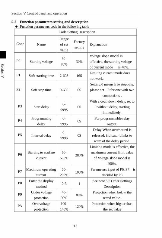
5-2 Function parameters setting and description
Function parameters code in the following table
Code Setting Description
Code Name
Range
of set
value
Factory
setting Explanation
P0 Starting voltage 30-
70% 30%
Voltage slope model is
effective, the starting voltage
of current mode is 40%.
P1 Soft starting time 2-60S 16S Limiting current mode does
not work.
P2 Soft stop time 0-60S 0S
Setting 0 means free stopping,
please set 0 for one with two
connections .
P3 Start delay 0-
999S 0S
With a countdown delay, set to
0 without delay, starting
immediately.
P4 Programming
delay
0-
999S 0S
For programmable relay
output.
P5 Interval delay 0-
999S 0S
Delay When overheated is
released, indicator blinks to
warn of the delay period.
P6 Starting to confine
current
50-
500% 280%
Limiting mode is effective, the
maximum current limit value
of Voltage slope model is
400%.
P7 Maximum operating
current
50-
200% 100%
Parameters input of P6, P7 is
decided by P8 .
P8 Enter the display
method 0-3 1
See note 5.5 Other Settings
Description
P9 Under voltage
protection
40-
90% 80%
Protection when below the
setted value .
PA Overvoltage
protection
100-
140% 120%
Protection when higher than
the set value
Section V Control panel and operation
13
Sectio
n V
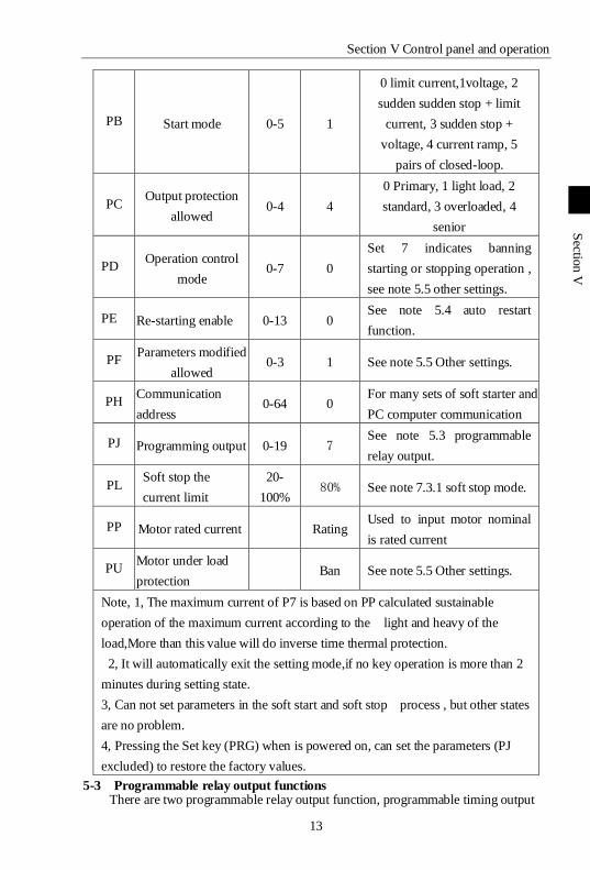
PB Start mode 0-5 1
0 limit current,1voltage, 2
sudden sudden stop + limit
current, 3 sudden stop +
voltage, 4 current ramp, 5
pairs of closed-loop.
PC Output protection
allowed 0-4 4
0 Primary, 1 light load, 2
standard, 3 overloaded, 4
senior
PD Operation control
mode 0-7 0
Set 7 indicates banning
starting or stopping operation ,
see note 5.5 other settings.
PE Re-starting enable 0-13 0 See note 5.4 auto restart
function.
PF Parameters modified
allowed 0-3 1 See note 5.5 Other settings.
PH Communication
address 0-64 0
For many sets of soft starter and
PC computer communication
PJ Programming output 0-19 7 See note 5.3 programmable
relay output.
PL Soft stop the
current limit
20-
100% 80% See note 7.3.1 soft stop mode.
PP Motor rated current Rating Used to input motor nominal
is rated current
PU Motor under load
protection Ban See note 5.5 Other settings.
Note, 1, The maximum current of P7 is based on PP calculated sustainable
operation of the maximum current according to the light and heavy of the
load,More than this value will do inverse time thermal protection.
2, It will automatically exit the setting mode,if no key operation is more than 2
minutes during setting state.
3, Can not set parameters in the soft start and soft stop process , but other states
are no problem.
4, Pressing the Set key (PRG) when is powered on, can set the parameters (PJ
excluded) to restore the factory values.
5-3 Programmable relay output functions There are two programmable relay output function, programmable timing output
Section V Control panel and operation
14
Sectio
n V
way and programmable state output way.
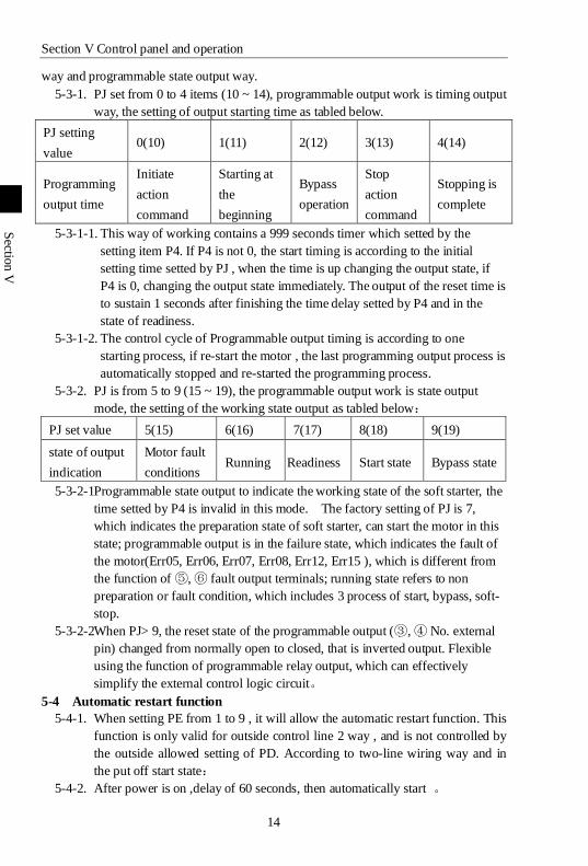
5-3-1. PJ set from 0 to 4 items (10 ~ 14), programmable output work is timing output
way, the setting of output starting time as tabled below.
PJ setting
value 0(10) 1(11) 2(12) 3(13) 4(14)
Programming
output time
Initiate
action
command
Starting at
the
beginning
Bypass
operation
Stop
action
command
Stopping is
complete
5-3-1-1. This way of working contains a 999 seconds timer which setted by the
setting item P4. If P4 is not 0, the start timing is according to the initial
setting time setted by PJ , when the time is up changing the output state, if
P4 is 0, changing the output state immediately. The output of the reset time is
to sustain 1 seconds after finishing the time delay setted by P4 and in the
state of readiness.
5-3-1-2. The control cycle of Programmable output timing is according to one
starting process, if re-start the motor , the last programming output process is
automatically stopped and re-started the programming process.
5-3-2. PJ is from 5 to 9 (15 ~ 19), the programmable output work is state output
mode, the setting of the working state output as tabled below:
PJ set value 5(15) 6(16) 7(17) 8(18) 9(19)
state of output
indication
Motor fault
conditions Running Readiness Start state Bypass state
5-3-2-1Programmable state output to indicate the working state of the soft starter, the
time setted by P4 is invalid in this mode. The factory setting of PJ is 7,
which indicates the preparation state of soft starter, can start the motor in this
state; programmable output is in the failure state, which indicates the fault of
the motor(Err05, Err06, Err07, Err08, Err12, Err15 ), which is different from
the function of ⑤, ⑥ fault output terminals; running state refers to non
preparation or fault condition, which includes 3 process of start, bypass, soft-
stop.
5-3-2-2When PJ> 9, the reset state of the programmable output (③, ④ No. external
pin) changed from normally open to closed, that is inverted output. Flexible
using the function of programmable relay output, which can effectively
simplify the external control logic circuit。
5-4 Automatic restart function
5-4-1. When setting PE from 1 to 9 , it will allow the automatic restart function. This
function is only valid for outside control line 2 way , and is not controlled by
the outside allowed setting of PD. According to two-line wiring way and in
the put off start state:
5-4-2. After power is on ,delay of 60 seconds, then automatically start 。
Section V Control panel and operation
15
Sectio
n V
5-4-3. After stop, automatically restart after delaying 60 seconds, but if the time
setting of P5 more than 60 seconds, the delay time is according to P5. During
delay time the state indicator flashes。
5-4-4. The total automatically start times can be N, Including power-on start and
restart after a failure. N is the setting value of PE. Auto-start mode must be
again on electricity then take effective , and it is effective again after the
power is on for every time。
5-4-5. When PE is set to 10, banned the function of losing electric protection . When
the power is on, if the outside control terminal is in a closed state, then
automatic starter motor, which means allows the electric start-up.
5-4-6. When PE is set to 11, it can re-start after failure: When the external control of
instantaneous stop terminal ⑦ is not prohibited ( PC> 0), or occurred the fault
of instantaneous stop, overheating, overvoltage, under voltage and then
recovery, can start the motor again without reset.
5-4-7. When PE is set to12, banned the function of losing electric protection and
restart after fault。
5-4-8. When PE is set to 13, running the function of memory recovery. During the
running of bypass state , the power is off and then is on, the soft starter will
auto-start recovery bypass operation。
5-4-9. Warning: The soft starter with the function of voltage-absent protection ,
when the power is off and then on, no matter the external control terminals in
what position,it won't self-starting, so as to avoid injuries. But when the
automatic restart function allows, banned the function of losing electric
protection , allowing the memory running resume function, the function of
losing electric protection will fail!
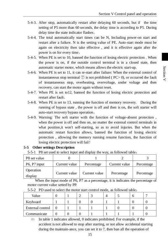
5-5 Other settings Description
5-5-1 P8 set used to select input and display the way, as followed table:
P8 set value 0 1 2 3
P6, P7 input Current value Percentage Current value Percentage
Operation
display Current value Current value Percentage Percentage
When the input mode of P6, P7 as a percentage, it is indicates the percentage of motor current value setted by PP.
5-5-2 PD used to select the motor start control mode, as followed table:
Value 0 1 2 3 4 5 6 7
Keyboard 1 1 0 0 1 1 0 0
External control 0 1 1 1 1 0 0 0
Communicate 0 0 0 1 1 1 1 0
⑴ In table 1 indicates allowed, 0 indicates prohibited. For example, if the
accident is not allowed to stop after starting, or not allow accidental starting
during the maintain-ance, you can set it to 7, then ban all the operation of
Section V Control panel and operation
16
Sectio
n V
starting and stopping
⑵ When the external control allows, the external control terminal ⑧, ⑩ must be
connected by a normally closed switch or shorted , or can not start the motor.
5-5-3 PF is the selection of allowing to modify parameter, there are three options:
⑴ PF is setted to 0, it is prohibited to modify any parameter in addition to PF.
⑵ PF is setted to 1, it is prohibited to modify P4, P7, P8, PE, PH, PJ, PL, PU
parameters。
⑶ PF is setted to 2, it is allowed to modify all the parameters.
5-5-4 PU is used to set the motor under load protection。
5-5-4-1 PU <10, the motor under load protection is prohibited.
5-5-4-2 The range of low load current protection is 10% to 90% of the motor
rated current, it is decided by the ten digits of PU.
5-5-4-3 The delay time of low load is ranging from 5 to 90 seconds, it is setted
by 10 times of PU digit. If the PU digit is 0, the protection operation
delays 5 seconds. For example,PU = 42, indicates the low load current is
40% , the delay time of protection action is 20 seconds。
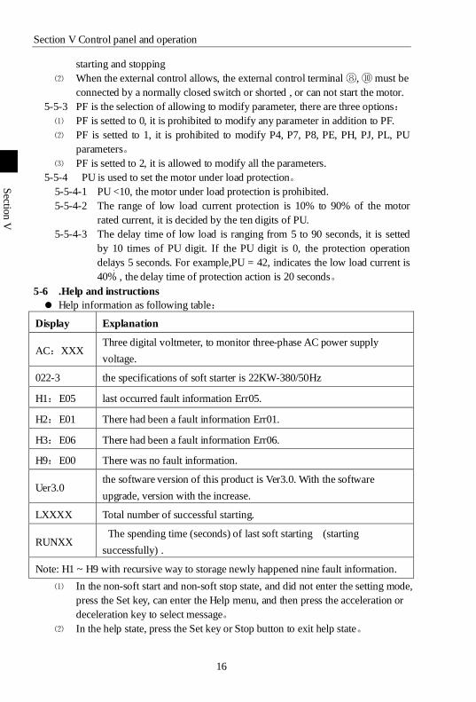
5-6 .Help and instructions
Help information as following table:
Display Explanation
AC:XXX Three digital voltmeter, to monitor three-phase AC power supply
voltage.
022-3 the specifications of soft starter is 22KW-380/50Hz
H1:E05 last occurred fault information Err05.
H2:E01 There had been a fault information Err01.
H3:E06 There had been a fault information Err06.
H9:E00 There was no fault information.
Uer3.0 the software version of this product is Ver3.0. With the software
upgrade, version with the increase.
LXXXX Total number of successful starting.
RUNXX The spending time (seconds) of last soft starting (starting
successfully) .
Note: H1 ~ H9 with recursive way to storage newly happened nine fault information.
⑴ In the non-soft start and non-soft stop state, and did not enter the setting mode,
press the Set key, can enter the Help menu, and then press the acceleration or
deceleration key to select message。
⑵ In the help state, press the Set key or Stop button to exit help state。
17
第
十
章
Ch
apter
Ⅵ
Section Ⅵ Protection and description
PR5200 series soft starter with complete protection to protect the safety of soft
starter and motor. During the application, appropriate protection parameters and level
should be setted based on different situation.
6-1 Protection functions and their parameters
6-1-1. Soft starter over-temperature protection: the temperature rose to 80 ℃ ± 5 ℃
over-temperature protection, when the temperature dropped to 55 ℃ (the
lowest), no over-temperature protection。
6-1-2. Input phase protection lag time : <3 seconds。
6-1-3. Three-phase unbalance protection lag time: <3 seconds.
6-1-4. Three-phase unbalance protection lag time: <3 seconds.It is based on the
deviation of all phase current greater than 50% ± 10% . When the load
current is lower than 30% of the nominal rating of soft starter, the benchmark
deviation will increase.
6-1-5. Starting time of over current protection: continuous 5 times greater than the
maximum operating current of the protection time setted byP7 in Table 6.1。
6-1-6. Time of running overload protection, it is based on the maximum operating
current of P7 and doing the inverse thermal protection, trip protection time
curve shows on Chart 6.1.
6-1-7. The protection lag time of much too low supply voltage, when the power
supply voltage is lower than the 40% of limit, the protection time <0.5
seconds, or the protection time <3 seconds if it is lower than the setting value.
6-1-8. The protection lag time of much too high supply voltage : when the power
supply voltage is lower than the 140% of limit, the protection time <0.5
seconds, or the protection time <3 seconds if it is higher than the setting
value.
6-1-9. The protection delay time of load short-circuit : <0.1 seconds, the current is
10 times more than soft starter nominal rated current. This protection can not
replace fuse short-circuit protection device.
6-1-10. Motor under load protection, the current range is 10% to 90% of motor rated
current, the protection action delay from 5 to 90 seconds。
These time parameters are from tested effective signal to a tripping protection
instructions, and the parameters just for reference. All the protection functions of
Section Ⅵ Protection and description
18
Ch
apter
Ⅵ
PR5200 series soft starter can be verified through the actual or simulation method. If it
can't meet the user's requirements, special protection device should be added to ensure
safety。
6-2 Protection level setting description
6-2-1. In order to adapt to different applications, PR5200 series soft starter has five
protection level, there are 0: primary, 1: light load, 2: Standard 3: heavy, 4:
Advanced, it setted by PC setting. Among them,
6-2-1-1. Primary protection is against to the function of external terminal
instantaneous stop, meanwhile only remains the overheating, short circuit
and main circuit fault protection, it can be applied to needed emergency
start in unconditional occasion, such as fire systems, etc.
6-2-1-2. The three protection level of light load, standard load and overload have
the complete protection function. The difference is the time curves of
motor overloaded thermal protection are not the same. The time
parameters of motor thermal protection are as Table 6.1 and Chart 6.1.
6-2-1-3. High level of protection standards is stringent at start. Other protection
features parameters keep the same with standard protection set.
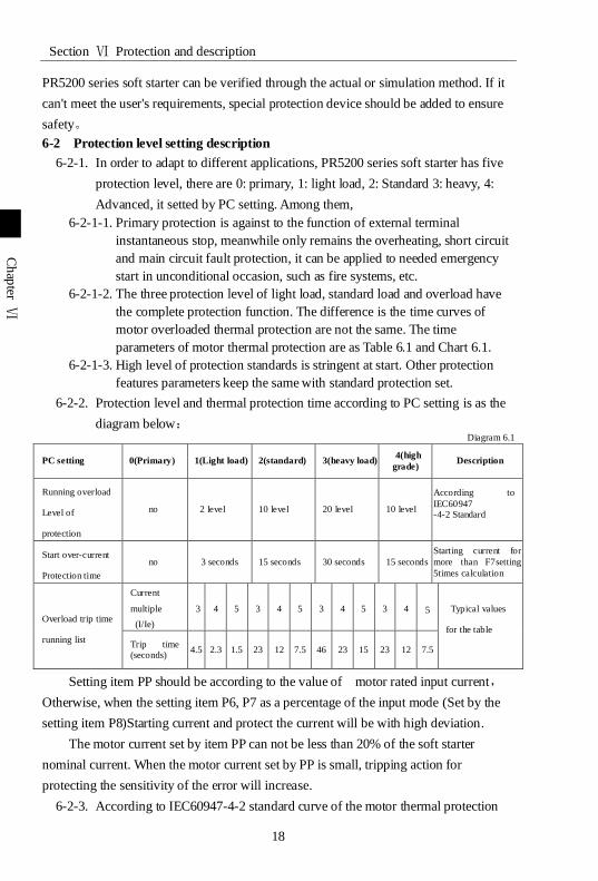
6-2-2. Protection level and thermal protection time according to PC setting is as the
diagram below: Diagram 6.1
PC setting 0(Primary) 1(Light load) 2(standard) 3(heavy load) 4(high
grade) Description
Running overload
Level of
protection
no 2 level 10 level 20 level 10 level
According to
IEC60947 -4-2 Standard
Start over-current
Protection time
no 3 seconds 15 seconds 30 seconds 15 seconds
Starting current for
more than F7setting
5times calculation
Overload trip time
running list
Current
multiple
(I/Ie)
3 4 5 3 4 5 3 4 5 3 4 5 Typical values
for the table
Trip time (seconds)
4.5 2.3 1.5 23 12 7.5 46 23 15 23 12 7.5
Setting item PP should be according to the value of motor rated input current,
Otherwise, when the setting item P6, P7 as a percentage of the input mode (Set by the
setting item P8)Starting current and protect the current will be with high deviation.
The motor current set by item PP can not be less than 20% of the soft starter
nominal current. When the motor current set by PP is small, tripping action for
protecting the sensitivity of the error will increase.
6-2-3. According to IEC60947-4-2 standard curve of the motor thermal protection
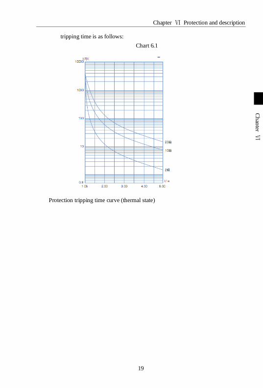
Chapter Ⅵ Protection and description
19
Ch
apter
Ⅵ
tripping time is as follows:
Chart 6.1
Protection tripping time curve (thermal state)
20
第
十
章
Sectio
n V
II
Section VII Test runing and application
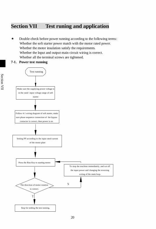
Double-check before power running according to the following terms:
Whether the soft starter power match with the motor rated power.
Whether the motor insulation satisfy the requirements.
Whether the Input and output main circuit wiring is correct.
Whether all the terminal screws are tightened.
7-1. Power test running
Test running
Make sure the supplying power voltage is
in the rated input voltage range of soft
starter
Follow 4-1 wiring diagram of soft starter, make
sure phase sequence connection of the bypass
contactor is correct, then power is on.
Setting PP according to the input rated current
of the motor plate
Press the Run Key to starting motor
The direction of motor rotation
is correct.
To stop the machine immediately, and cut off
the input power and changing the reversing
wiring of the main loop.
Stop for ending the test running.
N
Y
Section VII Test runing and application
21
Sectio
n V
II
Sectio
n V
II
7-1-1. If the motor starter status is not satisfactory, Refer to 7.2 of the soft starter
starting mode and application to select appropriate starting model.
7-1-2. If the motor starting torque is not enough, you can change the starting voltage
(voltage mode) or current-limiting value (current mode), to improve the motor
starting torque.
7-1-3. When soft starter power on, do not open the cover, to avoid electric shock.
7-1-4. In the power test of running, if appearing unusual phenomena, such as
abnormal noise, smoke or odor, etc., should be quickly cut off the power and
make further investigation.
7-1-5. If power on or when starting, appearing failure light and display ErrXX, you
can find the reason according to the displayed fault code and the
corresponding chapter of the cause.Press the stop button or external stop
button to reset the fault status.
Note:
⑴ When the ambient temperature is below -10 ℃, should power on for more
than 30 minutes to warm-up before starting.
⑵ When the soft starter drive the motor successfully, the operation status
indicator on the middle panel lights, that proves the bypass is in running status.
If at this time, the motor stop by bypass contactor without actuation,y ou
should check the bypass contactor and associated wiring connection.
7-2. PR5200 Series soft starter starting mode and application
PR5200 series soft starter has six models to suit a variety of complex starter motor
and load conditions, the user can choose it as different application.
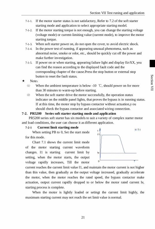
7-2-1 Current limit starting mode
When setting PB to 0, Set the start mode
for this mode.
Chart 7.1 shows the current limit mode
of the motor starting current waveform
changes. I1 is starting current limit by
setting, when the motor starts, the output
voltage rapidly increases, Till the motor
current reaches the current limit value I1, and maintain the motor current is not higher
than this value, then gradually as the output voltage increased, gradually accelerate
the motor, when the motor reaches the rated speed, the bypass contactor make
actuation, output current rapidly dropped to or below the motor rated current Ie,
starting process is complete.
When the motor is lightly loaded or setingt the current limit highly, the
maximum starting current may not reach the set limit value is normal.
Section VII Test runing and application
22
Sectio
n V
II
Sectio
n V
II
Current limit starting mode is generally used for a strictly limited starting
current requirements of the occasion.
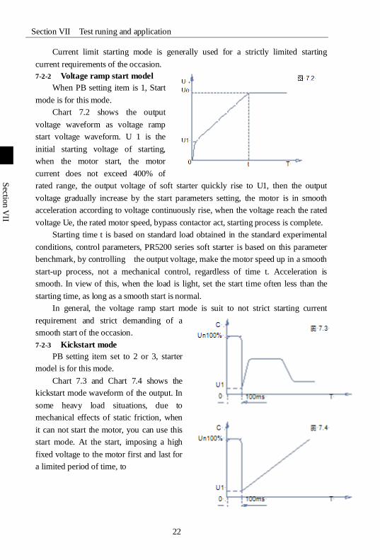
7-2-2 Voltage ramp start model
When PB setting item is 1, Start
mode is for this mode.
Chart 7.2 shows the output
voltage waveform as voltage ramp
start voltage waveform. U 1 is the
initial starting voltage of starting,
when the motor start, the motor
current does not exceed 400% of
rated range, the output voltage of soft starter quickly rise to U1, then the output
voltage gradually increase by the start parameters setting, the motor is in smooth
acceleration according to voltage continuously rise, when the voltage reach the rated
voltage Ue, the rated motor speed, bypass contactor act, starting process is complete.
Starting time t is based on standard load obtained in the standard experimental
conditions, control parameters, PR5200 series soft starter is based on this parameter
benchmark, by controlling the output voltage, make the motor speed up in a smooth
start-up process, not a mechanical control, regardless of time t. Acceleration is
smooth. In view of this, when the load is light, set the start time often less than the
starting time, as long as a smooth start is normal.
In general, the voltage ramp start mode is suit to not strict starting current
requirement and strict demanding of a
smooth start of the occasion.
7-2-3 Kickstart mode
PB setting item set to 2 or 3, starter
model is for this mode.
Chart 7.3 and Chart 7.4 shows the
kickstart mode waveform of the output. In
some heavy load situations, due to
mechanical effects of static friction, when
it can not start the motor, you can use this
start mode. At the start, imposing a high
fixed voltage to the motor first and last for
a limited period of time, to
Section VII Test runing and application
23
Sectio
n V
II
Sectio
n V
II
Before using this model, start motor with non-sudden jump model, if the motor
can not move due to static friction, then use this model; otherwise avoid to start this
mode to reduce the unnecessary high current impact.
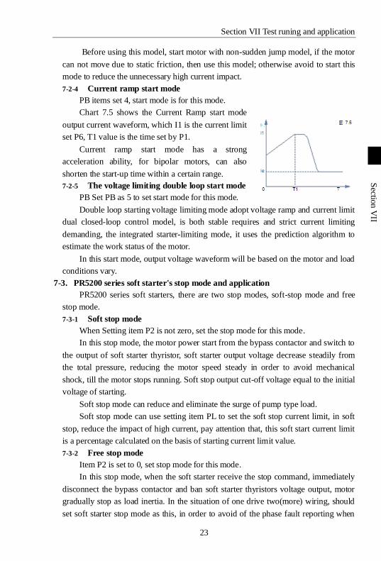
7-2-4 Current ramp start mode
PB items set 4, start mode is for this mode.
Chart 7.5 shows the Current Ramp start mode
output current waveform, which I1 is the current limit
set P6, T1 value is the time set by P1.
Current ramp start mode has a strong
acceleration ability, for bipolar motors, can also
shorten the start-up time within a certain range.
7-2-5 The voltage limiting double loop start mode
PB Set PB as 5 to set start mode for this mode.
Double loop starting voltage limiting mode adopt voltage ramp and current limit
dual closed-loop control model, is both stable requires and strict current limiting
demanding, the integrated starter-limiting mode, it uses the prediction algorithm to
estimate the work status of the motor.
In this start mode, output voltage waveform will be based on the motor and load
conditions vary.
7-3. PR5200 series soft starter's stop mode and application
PR5200 series soft starters, there are two stop modes, soft-stop mode and free
stop mode.
7-3-1 Soft stop mode
When Setting item P2 is not zero, set the stop mode for this mode.
In this stop mode, the motor power start from the bypass contactor and switch to
the output of soft starter thyristor, soft starter output voltage decrease steadily from
the total pressure, reducing the motor speed steady in order to avoid mechanical
shock, till the motor stops running. Soft stop output cut-off voltage equal to the initial
voltage of starting.
Soft stop mode can reduce and eliminate the surge of pump type load.
Soft stop mode can use setting item PL to set the soft stop current limit, in soft
stop, reduce the impact of high current, pay attention that, this soft start current limit
is a percentage calculated on the basis of starting current limit value.
7-3-2 Free stop mode
Item P2 is set to 0, set stop mode for this mode.
In this stop mode, when the soft starter receive the stop command, immediately
disconnect the bypass contactor and ban soft starter thyristors voltage output, motor
gradually stop as load inertia. In the situation of one drive two(more) wiring, should
set soft starter stop mode as this, in order to avoid of the phase fault reporting when
Section VII Test runing and application
24
Sectio
n V
II
Sectio
n V
II
output switching.
Under normal circumstances, if not necessary soft stop, stop mode should be
free stop model, to extend the life of the soft starter.
As stop model completely ban the instantaneous output, can avoid an
instantaneous high-current impact in special applications.
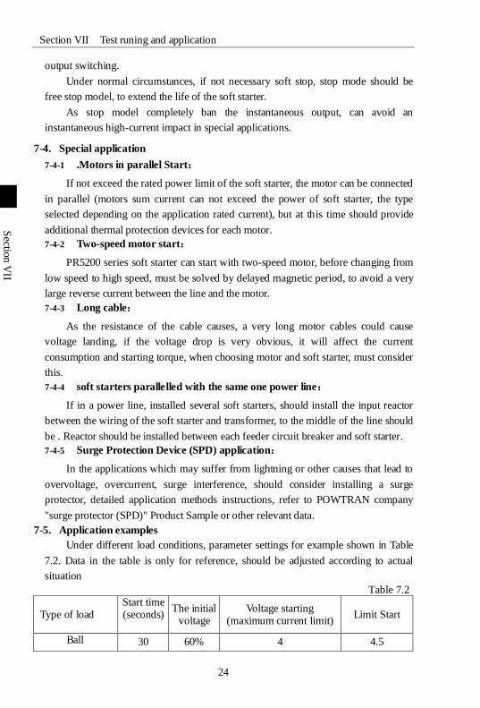
7-4. Special application
7-4-1 .Motors in parallel Start:
If not exceed the rated power limit of the soft starter, the motor can be connected
in parallel (motors sum current can not exceed the power of soft starter, the type
selected depending on the application rated current), but at this time should provide
additional thermal protection devices for each motor.
7-4-2 Two-speed motor start:
PR5200 series soft starter can start with two-speed motor, before changing from
low speed to high speed, must be solved by delayed magnetic period, to avoid a very
large reverse current between the line and the motor.
7-4-3 Long cable:
As the resistance of the cable causes, a very long motor cables could cause
voltage landing, if the voltage drop is very obvious, it will affect the current
consumption and starting torque, when choosing motor and soft starter, must consider
this.
7-4-4 soft starters parallelled with the same one power line:
If in a power line, installed several soft starters, should install the input reactor
between the wiring of the soft starter and transformer, to the middle of the line should
be . Reactor should be installed between each feeder circuit breaker and soft starter.
7-4-5 Surge Protection Device (SPD) application:
In the applications which may suffer from lightning or other causes that lead to
overvoltage, overcurrent, surge interference, should consider installing a surge
protector, detailed application methods instructions, refer to POWTRAN company
"surge protector (SPD)" Product Sample or other relevant data.
7-5. Application examples
Under different load conditions, parameter settings for example shown in Table
7.2. Data in the table is only for reference, should be adjusted according to actual
situation
Table 7.2
Type of load Start time (seconds)
The initial voltage
Voltage starting (maximum current limit)
Limit Start
Ball 30 60% 4 4.5

Section VII Test runing and application
25
Sectio
n V
II
Sectio
n V
II
Fans 26 30% 4 3.5
Centrifugal pump 16 40% 4 2.5
Piston compressor 16 40% 4 3
Enhance the mechanical
16 60% 4 3.5
Mixer 16 50% 4 3
Crusher 16 50% 4 3.5
Screw compressor 16 40% 4 3
Screw conveyor 20 40% 4 2
Light load motor 16 30% 4 3
Belt conveyors 20 40% 4 2.5
Heat pump 16 40% 4 3
26
第
十
章
第
十
章
第
十
章
Sectio
n V
III
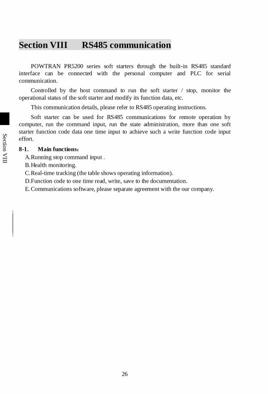
Section VIII RS485 communication
POWTRAN PR5200 series soft starters through the built-in RS485 standard
interface can be connected with the personal computer and PLC for serial
communication.
Controlled by the host command to run the soft starter / stop, monitor the
operational status of the soft starter and modify its function data, etc.
This communication details, please refer to RS485 operating instructions.
Soft starter can be used for RS485 communications for remote operation by
computer, run the command input, run the state administration, more than one soft
starter function code data one time input to achieve such a write function code input
effort.
8-1. Main functions:
A.Running stop command input .
B. Health monitoring.
C. Real-time tracking (the table shows operating information).
D.Function code to one time read, write, save to the documentation.
E. Communications software, please separate agreement with the our company.
27
第
十
章
Sectio
n IX
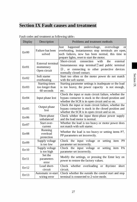
Section IX Fault causes and treatment
Fault codes and treatment as following table:
Display Description Problems and treatment methods
Err00 Failure has been
solved
Just happened undervoltage, overvoltage or overheating, instantaneous stop terminals are open, such failures, now has been normal, this time to prepare lights, reset to start the motor.
Err01 External terminal momentary Open circuit
Short-circuit connection with the external
Instantaneous stop terminal⑦and public terminal
⑩ , or connecting to other protective devices normally closed contact.
Err02 Soft starter overheating
Start too often or the motor power do not match with the soft starter.
Err03 Starting times
too longer than 60 seconds
Starting parameter settings is inadequate or the load is too heavy, the power capacity is not enough, etc.
Err04 Input phase lost Check the input or main circuit failure, whether the bypass contactor is stuck in the closed position and whether the SCR is in open circuit and so on.
Err05 Output phase
lost
Check the input or main circuit failure, whether the bypass contactor is stuck in the closed position and whether the SCR is in open circuit and so on.
Err06 Three-phase unbalanced
Check whther the input three-phase power supply and the load motor is normal.
Err07 Start over-
current Whether the load is too heavy or motor power does not match with soft starter.
Err08 Running overload
protection
Whether the load is too heavy or setting items P7, PP parameters set incorrectly.
Err09 Supply voltage
is too low Check the input voltage or setting item P9 parameter set incorrectly.
Err10 Supply voltage
is too high Check the input voltage or setting item PA parameter set incorrectly.
Err11 Set the
parameters error
Modify the settings, or pressing the Enter key on power to restore the factory values.
Err12 Load short-
circuit Check whether overloading or thyristor short circuit.
Err13 Automatic re-start
wiring error Check whether the outside the control start and stop terminal is connected to 2-wire mode.
Section IX Fault causes and treatment
28
Sectio
n IX
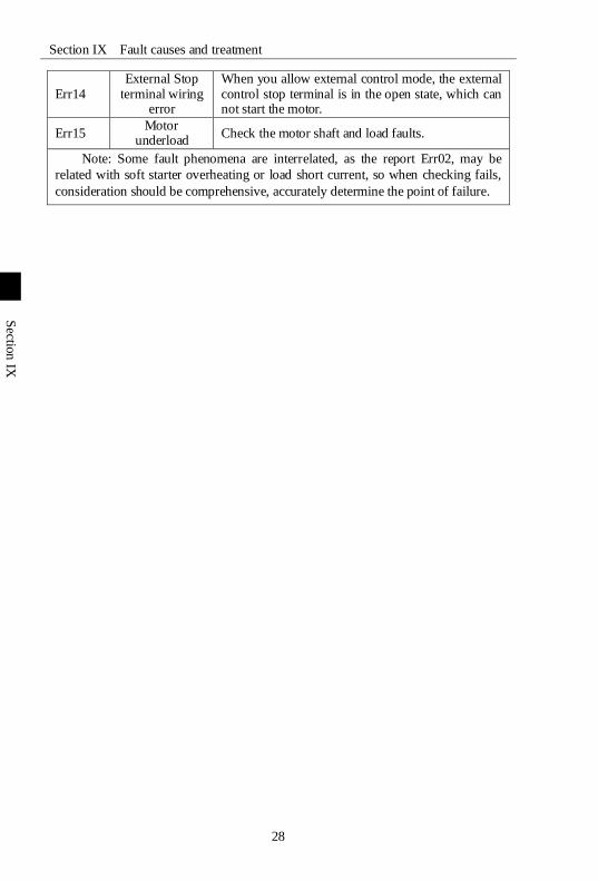
Err14 External Stop
terminal wiring error
When you allow external control mode, the external control stop terminal is in the open state, which can not start the motor.
Err15 Motor
underload Check the motor shaft and load faults.
Note: Some fault phenomena are interrelated, as the report Err02, may be
related with soft starter overheating or load short current, so when checking fails,
consideration should be comprehensive, accurately determine the point of failure.
29
第
十
章
Sectio
n X
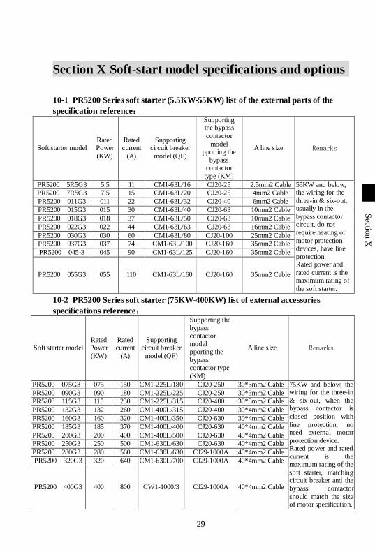
Section X Soft-start model specifications and options
10-1 PR5200 Series soft starter (5.5KW-55KW) list of the external parts of the
specification reference:
Soft starter model Rated Power
(KW)
Rated current
(A)
Supporting circuit breaker
model (QF)
Supporting the bypass
contactor
model pporting the
bypass contactor
type (KM)
A line size Remarks
PR5200 5R5G3 5.5 11 CM1-63L/16 CJ20-25 2.5mm2 Cable 55KW and below, the wiring for the
three-in & six-out, usually in the
bypass contactor circuit, do not
require heating or
motor protection devices, have line
protection. Rated power and
rated current is the maximum rating of
the soft starter.
PR5200 7R5G3 7.5 15 CM1-63L/20 CJ20-25 4mm2 Cable
PR5200 011G3 011 22 CM1-63L/32 CJ20-40 6mm2 Cable
PR5200 015G3 015 30 CM1-63L/40 CJ20-63 10mm2 Cable
PR5200 018G3 018 37 CM1-63L/50 CJ20-63 10mm2 Cable
PR5200 022G3 022 44 CM1-63L/63 CJ20-63 16mm2 Cable
PR5200 030G3 030 60 CM1-63L/80 CJ20-100 25mm2 Cable
PR5200 037G3 037 74 CM1-63L/100 CJ20-160 35mm2 Cable
PR5200 045-3 045 90 CM1-63L/125 CJ20-160 35mm2 Cable
PR5200 055G3 055 110 CM1-63L/160 CJ20-160 35mm2 Cable
10-2 PR5200 Series soft starter (75KW-400KW) list of external accessories
specifications reference:
Soft starter model Rated Power
(KW)
Rated current
(A)
Supporting circuit breaker
model (QF)
Supporting the
bypass contactor
model pporting the
bypass contactor type
(KM)
A line size Remarks
PR5200 075G3 075 150 CM1-225L/180 CJ20-250 30*3mm2 Cable 75KW and below, the wiring for the three-in
& six-out, when the bypass contactor is
closed position with
line protection, no need external motor
protection device. Rated power and rated
current is the maximum rating of the
soft starter, matching circuit breaker and the
bypass contactor
should match the size of motor specification.
PR5200 090G3 090 180 CM1-225L/225 CJ20-250 30*3mm2 Cable
PR5200 115G3 115 230 CM1-225L/315 CJ20-400 30*3mm2 Cable
PR5200 132G3 132 260 CM1-400L/315 CJ20-400 30*4mm2 Cable
PR5200 160G3 160 320 CM1-400L/350 CJ20-630 30*4mm2 Cable
PR5200 185G3 185 370 CM1-400L/400 CJ20-630 40*4mm2 Cable
PR5200 200G3 200 400 CM1-400L/500 CJ20-630 40*4mm2 Cable
PR5200 250G3 250 500 CM1-630L/630 CJ20-630 40*4mm2 Cable
PR5200 280G3 280 560 CM1-630L/630 CJ29-1000A 40*4mm2 Cable
PR5200 320G3 320 640 CM1-630L/700 CJ29-1000A 40*4mm2 Cable
PR5200 400G3 400 800 CW1-1000/3 CJ29-1000A 40*4mm2 Cable
30
第
十
章
Sectio
n X
I
Section XI Quality Assurance
This product quality assurance is in accordance with the following provisions:
1. Indeed the responsibility of the manufacturer, quality assurance details:
1-1. When used in the China (to the date of shipment)
※ Within one month after shipping, refund, replacement,
※ Within three months after shipment, replacement, repair.
※ Within 15 months after delivery, repair.
1-2. Export to overseas (excluding demestic), the ship within six months after
purchase, be responsible for repair.
2. No matter when and where, use of our brand's products, enjoy the paid services
for all life.
3. The Company's sales throughout the country, production, all agents can provide
service to this product, their service conditions:
3-1 Location of the unit to "3" inspection services (including troubleshooting).
3-2 Be in accordance with these companies and distribution agents in relation to
service, the contract responsibility standards.
3-3 Can be paid to the general mass of the distribution agent, the request for after-
sales service (whether or not the warranty).
4. Quality of the product or products appear responsible for the accident, up to 1-1 or
1-2 terms only assume the responsibility, if you need more liability guarantee,
prior to your own property insurance in insurance companies.
5. This product is warranted for one year from the date of shipment.
6. In the case of the following causes of failure, even during the warranty period is
also a paid repair:
6-1 Incorrect operation (according to manual date), or caused by modified without
permission to repair the problems.
6-2 Beyond the standard specification requires, problems caused by the use of the
the soft starter.
6-3 After purchasing, loss or damage caused by improper handling.
6-4 The device poor or failure caused by environmental aging.
6-5 Due to earthquake, fire, wind and flood damage, lightning, abnormal voltage or
accompanied by other natural disasters damage.
6-6 Damage during transport (Note: The mode of transport specified by the client .
Our company assist on behalf of the procedures for transfer of goods).
6-7 Manufacturer's brand label, trademark, serial number, nameplate and other
damaged or unreadable.
6-8 Purchase agreement is not paid in money.
6-9 For installation, wiring, operation, maintenance or other use of objective reality
can not be described to the Company's service units.
7. For refund, replacement, repair services, goods shall be returned to the company,
confirmed the attribution of responsibility, before be returned or repai
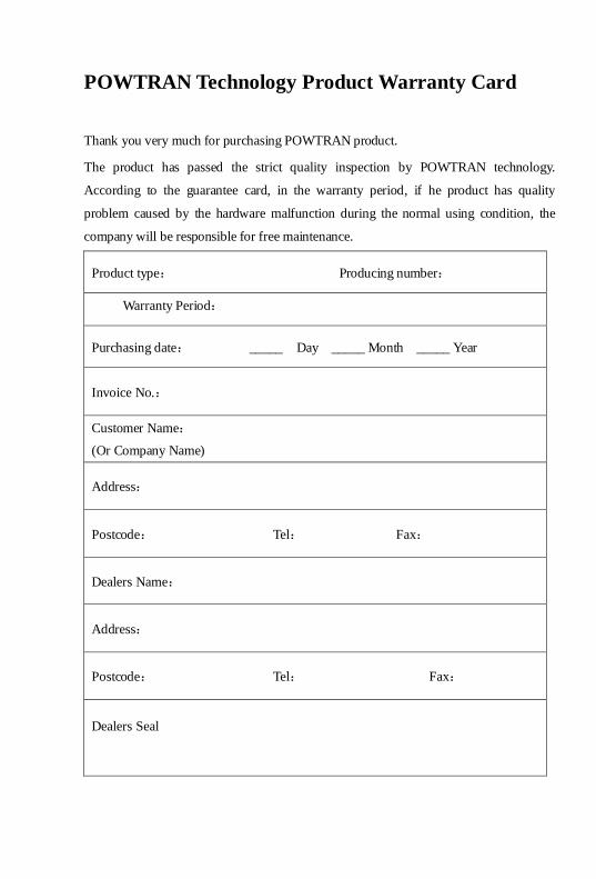
POWTRAN Technology Product Warranty Card
Thank you very much for purchasing POWTRAN product.
The product has passed the strict quality inspection by POWTRAN technology.
According to the guarantee card, in the warranty period, if he product has quality
problem caused by the hardware malfunction during the normal using condition, the
company will be responsible for free maintenance.
Product type: Producing number:
Warranty Period:
Purchasing date: _____ Day _____ Month _____ Year
Invoice No.:
Customer Name:
(Or Company Name)
Address:
Postcode: Tel: Fax:
Dealers Name:
Address:
Postcode: Tel: Fax:
Dealers Seal
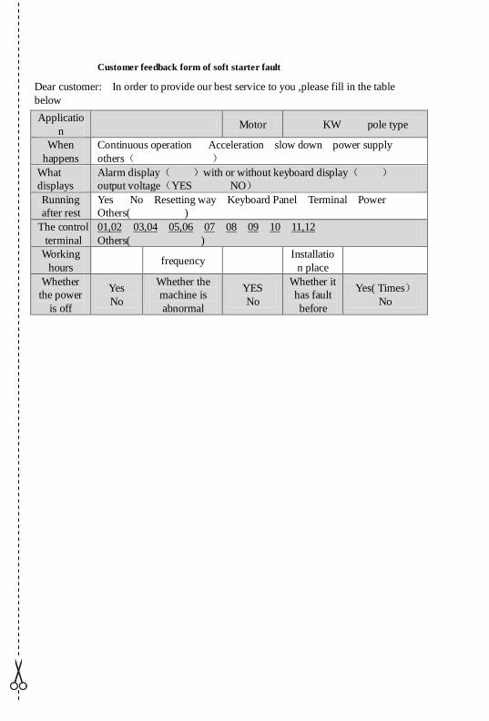
Customer feedback form of soft starter fault
Dear customer: In order to provide our best service to you ,please fill in the table
below
Applicatio
n Motor KW pole type
When
happens
Continuous operation Acceleration slow down power supply
others( )
What
displays
Alarm display( )with or without keyboard display( )
output voltage(YES NO)
Running
after rest
Yes No Resetting way Keyboard Panel Terminal Power
Others( )
The control
terminal
01,02 03,04 05,06 07 08 09 10 11,12
Others( )
Working
hours frequency
Installatio
n place
Whether
the power
is off
Yes
No
Whether the
machine is
abnormal
YES
No
Whether it
has fault
before
Yes( Times)No
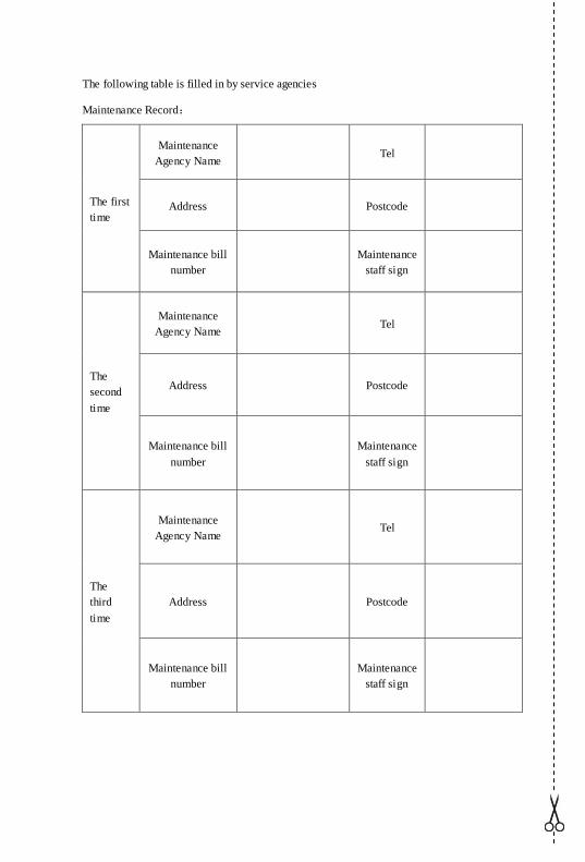
The following table is filled in by service agencies
Maintenance Record:
The first
time
Maintenance
Agency Name Tel
Address Postcode
Maintenance bill
number
Maintenance
staff sign
The
second
time
Maintenance
Agency Name Tel
Address Postcode
Maintenance bill
number
Maintenance
staff sign
The
third
time
Maintenance
Agency Name Tel
Address
Postcode
Maintenance bill
number
Maintenance
staff sign
Product information feedback Dear users:
Thank you for your attention and purchasing POWTRAN technology products! In order to
serve you better, we hope to get your personal general information about using POWTRAN
technology products, your now and future demand on POWTRAN technology products, gain for
your valuable feedback. To facilitate as early as possible when you need our services, please visit
the company website POWTRAN technology Http://www.powtran.com "technologies and
services" and "Downloads" section for information feedback.
1) Download and update you product manual
2) Access to products, technical information, such as instructions, size characteristics, and
frequently asked questions
3) Application Case Share.
4) Technical consulting, on-line feedback
5) Feedback by the form of e-mail on product information and user needs information
6) For the latest products, access to all kinds of additional services and extended warran