formability of a high-strain-rate superplastic al–4.4cu–1.5mg/21sicw composite under biaxial...
TRANSCRIPT

Formability of a high-strain-rate superplastic Al�/4.4Cu�/1.5Mg/21SiCW composite under biaxial tension
K.C. Chan *, G.Q. Tong
Department of Manufacturing Engineering, The Hong Kong Polytechnic University, Hung Hom, Kowloon, Hong Kong
Received 12 October 2001; received in revised form 20 February 2002
Abstract
The cavitation behavior and forming limits of a high-strain-rate superplastic 21 vol.% SiC whisker-reinforced Al�/4.4Cu�/1.5Mg
(Al�/4.4Cu�/1.5Mg/21SiCW) under biaxial stress states were investigated in this paper. The composite sheet was bulged using dies
with aspect ratios of 1:1, 4:3 and 2:1 at the constant applied stress of 4 MPa and at the optimal temperature of 793 K determined
from superplastic tensile tests. The thickness distributions of bulged diaphragms were measured at different strain levels. For
diaphragms deformed equibiaxially, a good agreement between experimental thickness distributions and the theoretical predictions
of Cornfield and Johnson (Int. J. Mech. Sci. 12 (1970) 479) was observed at fractional heights of the deformed diaphragms ranging
from 0.4 to 1.0. The cavitation behavior of the composite under biaxial tension was compared with that of uniaxial tension. It was
found that at a similar effective strain, the amount of cavities obtained under equibiaxial tension is slightly greater than that under
uniaxial tension, and the cavity growth rate parameter under uniaxial tension was also slightly larger than that of uniaxial tension.
The influence of stress state on cavity growth rate was discussed. Limit strains of Al�/4.4Cu�/1.5Mg/21SiCW at different stress ratios
were predicted based on a plastic damage model recently developed for superplastic materials (Chan and Chow, Int. J. Mech. Sci.,
submitted). The trend of the prediction was in good agreement with the experimental findings.
# 2002 Elsevier Science B.V. All rights reserved.
Keywords: Aluminum-based composite; Superplasticity; Cavitation; Limit strains
1. Introduction
The discovery of high strain rate superplasticity
(HSRS) which is defined as the ability of a material to
achieve high tensile ductility at strain rates larger than
10�2 s�1 is significant because one of the major
disadvantages in the field of conventional superplasticity
is the low forming rate, typically in the range of 10�5�/
10�3 s�1. Since HSRS was originally reported in a 20
vol.% SiC whisker-reinforced Al2124 (Al2124/20SiCW)
[1] in 1984, many other materials, such as mechanically
alloyed aluminum alloys and its composites [2], magne-
sium-based composites [3] and zirconium or scandium
improved aluminum alloys [4], had demonstrated to
exhibit HSRS. HSRS materials are phenomenally asso-
ciated with grain sizes much finer than those conven-
tional superplastic monolithic materials. Furthermore,
the grain size of HSRS materials is relatively stable
during deformation as a result of large volume fraction
of ceramic whiskers/particles preventing excessive ma-
trix grain growth or dispersion of extremely fine
intermetallic particles pinning grain boundaries effec-
tively. One of the significant features of HSRS in
discontinuously reinforced metal matrix composites
(MMCs) is their optimal deformation temperatures
being close to or slightly above the solidus temperatures
of the composites [1,3]. Deformation models [5,6] for
HSRS MMCs have been successfully developed to
explain the experimental findings. The relatively high
forming rate of HSRS makes superplastic forming
technology more possible in commercial applications.
Near net-shape superplastic forming of sheet materials
has been well-documented for metal alloys [7�/10]. In
particular, gas pressure forming of superplastic materi-
als offers the specific technological advantage in a cost
effective and weight saving manner of producing net-
* Corresponding author. Tel.: �852-2766-4981; fax: �852-2362-
5267
E-mail address: [email protected] (K.C. Chan).
Materials Science and Engineering A340 (2003) 49�/57
www.elsevier.com/locate/msea
0921-5093/02/$ - see front matter # 2002 Elsevier Science B.V. All rights reserved.
PII: S 0 9 2 1 - 5 0 9 3 ( 0 2 ) 0 0 1 5 4 - 5

shape articles. Superplastic forming of Al-MMCs has
been explored in Al7475/SiCP [11], Al6061/20SiCW [12],
formability of Al2009/SiCW [13]. It was reported that an
Al6061/20SiCW hemispherical dome had been success-fully gas pressure formed in 17 seconds at the applied
flow stress of 4 MPa and at 873K [12]. Two main factors
influencing the formability of superplastic materials and
the quality of formed articles are thickness uniformity
and cavitation behavior. Assuming a spherical dome
profile, Cornfield and Johnson [8] have proposed an
analytical model to predict thickness variations in
superplastic bulging of domes, and demonstrated thatthe thickness non-uniformity increases as m value
decreases. Their predicted values are in good agreement
with the experimental findings. Yousif et al. [14] have
further reported that it is precise enough to assume an
elliptical profile in cold forming of sheet materials using
elliptical dies.
It is well established that most superplastic materials
undergo cavitation during deformation, and that thepresence of cavities may lead either to premature failure
or to degradation of the mechanical properties of post-
formed components. However, research work on the
cavitation behavior of HSRS Al-MMCs are at present
limited to Al6061/20Si3N4P [15], IN9021/15SiCP [16] and
Al2124/20Si3N4W(P) [17] and Al6061/20SiCW [18].
Furthermore, the cavitation behavior of Al-MMCs
deformed under complex stress states, which are com-monly observed in industrial processes, has drawn less
research attention. It has been demonstrated that cavity
growth is primarily controlled by the plastic flow of the
matrix rather than diffusion mechanisms. Some investi-
gations have been carried out for conventional super-
plastic aluminum alloys to examine the effect of stress
state on cavitation. It is interesting however to note that
some of the findings are conflicting [19,20]. More workneeds to be done to examine the effect of stress state on
cavitation of Al-MMCs.
There is also relatively less research work to examine
and predict limit strains of superplastic materials under
biaxial tension. Ding et al. [21] have developed a
simplified instability criterion based on the Marciniak
and Kucznski (M�/K) model [22] which assumes the
existence of an initial imperfection in the sheet whichwill develop into a groove. Based on the damage
mechanics approach and the M�/K model, Chan and
Tong [23] have developed an analytical model to predict
limit strains of a HSRS Al6061/20SiCW under equibiax-
ial tension. Chow and Chan [24] have recently extended
the damage model to predict the formability of super-
plastic Al5083 alloy under other biaxial stress states.
This model will be applied in the present paper, and thepredictions will be compared with the experimental
findings. The aim of this paper is hence to investigate
the thickness distribution and cavity behavior of a 21
vol.% SiC whisker-reinforced Al�/4.4Cu�/1.5Mg (Al�/
4.4Cu�/1.5Mg/21SiCW), and to utilize the damage model
[24] to predict the limit strains under biaxial tension.
2. Materials and experimental procedures
The Al�/4.4Cu�/1.5Mg/21SiCW composite sheet sup-plied by Advanced Composite Corp. was investigated in
present study. A typical scanning electron microscope
(SEM) micrograph of the composite is shown in Fig. 1,
indicating that the distribution of SiCW is reasonably
homogeneous. The solidus temperature of the composite
determined by a Du Pont 9900 differential scanning
calorimeter (DSC) was found to be �/792 K. The DSC
test was started at room temperature and ended at �/
873 K with a constant heating rate of 10 K min�1. It has
been reported by the authors [25] that the composite
exhibits a strain rate sensitivity exponent (m value) of
�/0.35 at the strain rate regime of 10�2�/100 s�1 and
at the temperature range of 723�/818 K. A maximum
elongation of about 335% was obtained by superplastic
tensile tests at the initial strain rate of 0.17 s�1 and at
the temperature of 793K which is defined as optimaltemperature. The corresponding flow stress is �/4 MPa.
It has also been reported that Al�/4.4Cu�/1.5Mg/21SiCW
composite exhibits the same m value of �/0.35 under
both uniaxial and equibiaxial tension [26].
Square Al�/4.4Cu�/1.5Mg/21SiCW discs of dimensions
65 mm�/65 mm�/2.28 mm were machined and photo-
printed with grid circles of 1.8115 mm in diameter.
Based on the tensile test results of the composite, HSRSgas pressure forming was performed in a fully compu-
terized tester [13] using dies with aspect ratio of 1:1, 4:3
and 2:1 at the constant applied stress of 4 MPa and at
the optimal temperature of 793 K. The surface strain
distributions of the gas pressure formed diaphragms
were obtained by measuring the grid circles under an
Fig. 1. SEM micrograph of as-received Al�/4.4Cu�/1.5Mg/21SiCW.
K.C. Chan, G.Q. Tong / Materials Science and Engineering A340 (2003) 49�/5750

optical microscopy, whereas the thickness strain of the
diaphragms was determined by using a ball point gauge.
Specimens were cut from the gauge area of the tensile
samples and from the top of the formed diaphragms.The volume fraction of cavities was determined by
measuring the specimen density in water with the
corresponding undeformed regions as the reference
density. After polishing, the specimens were also exam-
ined using a Leica Q500 image-analyzing system to
determine the volume fraction of cavity. Since the
volume fraction of cavities may be over-estimated by
the image analyzing technique due to the presence ofsecond phases, the measured volume fraction was
compared with that obtained by the density measure-
ment to ensure that errors are no more than 10%.
3. Experimental results
3.1. Strain distributions of bulged diaphragms
Fig. 2 shows the schematic diagram of a HSRS bulged
elliptical specimen. The die has an aperture of 2b in
length and 2a in width. The major and minor axes are
represented by OY and OX respectively. Based on theassumption that the major and minor profiles of the
diaphragm are approximately in circularity, the radii of
the curvature of the membrane in planes XOZ and YOZ
are described by rx �/(a2�/h2)/2h and ry �/(b2�/h2)/2h ,
respectively. For a circular bulging, i.e. a�/b , rx equals
to ry .
The thickness strain distributions of the composite
diaphragm bulged to the pole heights of 13.22 and 20.00mm using a die with aspect ratio of 1:1 are shown in Fig.
3. Based on the theoretical analysis of Cornfield and
Johnson [8], a computer program was written to predict
the thickness strain variations of superplastically bulged
domes. The theoretical thickness strains are also shown
in Fig. 3. The experimental results show a good
agreement with the theoretical values in the fractional
height (h /h0) ranging from 0.4 to 1.0. A relatively large
difference between the experimental and theoretical
results, however, occurs in the fractional height rangingfrom 0.0 to 0.4. The higher the dome height, the larger
the difference. One of the main reasons for the difference
is considered to be the fact that the equibiaxial tension
assumption used in the modelling work may not be valid
for most regions of the diaphragm [8]. In reality, the
equibiaxial tensile stress state only exists at the top of
dome. The dome edge is under the plane strain state and
most areas of the dome are subjected to biaxial tensilestresses. Moreover, the equilibrium equations of the
membrane theory which may also not be valid for the
region close to the edge, and materials which are allowed
to flow from the clamped portion into the die cavity are
other reasons for the discrepancy.
At pole heights of 12.99 and 9.32 mm, the strain
distributions of the diaphragm deformed in dies with
aspect ratios of 4:3 and 2:1 are shown in Figs. 4 and 5,respectively. It should be noted that the strain gradient
in the minor axis is much greater than that in the major
axis, and that the strain gradient observed in both axes
increases with increasing die aspect ratio. It is also
interesting to point out from Figs. 4 and 5 that the
volume strain, a o�/oX�/oY�/ot , does not equal to zero
and is inconsistent with the constant-volume principle.
This is considered to relate to the cavitation behavior ofthe HSRS Al-MMCs sheet during bulging, which
includes: (a) void nucleation; (b) cavity growth; and (c)
cavity aggregation and failure.
3.2. Cavitation behavior
Variation of cavity volume fraction with true strain of
the Al�/4.4Cu�/1.5Mg/21SiCW composite bulged equi-
biaxially at s�/4 PMa and stretched uniaxially at the
initial strain rate o0 of 0.17 s�1 [25] is shown in Fig. 6. Itis obvious that the amount of cavities increases with
increasing strain. Similar phenomenon has been re-
ported for some conventional superplastic metals andFig. 2. Schematic diagram of a HSRS bulged diaphragm.
Fig. 3. Comparisons between experimental thickness strain distribu-
tions (triangles and squares) with the theoretical distributions [8] (solid
lines) using m�0.35.
K.C. Chan, G.Q. Tong / Materials Science and Engineering A340 (2003) 49�/57 51

HSRS Al-MMCs [15�/19]. It reveals that, in general, the
amount of cavity resulting from equibiaxial tension is
slightly greater than that from uniaxial one. The
relationship between cavity volume fraction and strain
clearly illustrates an exponential relationship, indicating
that cavity growth is essentially plastic-controlled. Stow-
ell [27] proposed an analytical model to predict thevolume of cavities CV
CV�CV0exp(ho) (1)
where CV0
is the volume of cavities at zero strain, h is
the dimensionless cavity growth rate parameters, whichvaries according to material, grain size, strain rate and
temperature. CV0
and h values for the composite at
different stress ratios under biaxial tension are also
illustrated in Table 1. The cavity growth parameter
increases from 2.0 to 2.2 when the stress ratio increasing
from 0.6667 to 1.0. It is shown that a slightly larger h
value is observed under biaxial tension than that of
uniaxial one. The phenomenon is consistent with thereports of Pilling and Ridley [19]. They have reported
that the h values of Al7475 and Supal 220 are higher
under equibiaxial tension than under uniaxial tension.
For comparison purpose, the cavity behavior of
Al7475 alloy and Al6061/20Si3N4P deformed at theiroptimum conditions is also shown in Fig. 6. The h
values for HSRS Al�/4.4Cu�/1.5Mg/21SiCW, HSRS
Al6061/20Si3N4P [15] and Al7475 [15] under uniaxial
tension, as shown in Table 1, are 1.9, 0.5 and 3.6,
Fig. 4. Strain distributions on the (a) major and (b) minor axis for Al�/
4.4Cu�/1.5Mg/21SiCW diaphragm bulged in a die with aspect ratio of
4:3 at s�4 MPa and at 793 K.Fig. 5. Strain distributions on the (a) major and (b) minor axis for Al�/
4.4Cu�/1.5Mg/21SiCW diaphragm bulged in a die with aspect ratio of
2:1 at s�4 MPa and at 793 K.
Fig. 6. Variation of volume of cavity with true local strain for Al�/
4.4Cu�/1.5Mg/21SiCW deformed at 793K.
K.C. Chan, G.Q. Tong / Materials Science and Engineering A340 (2003) 49�/5752

respectively. A higher h value means that cavity is more
sensitive to plastic strain. It is noted that the testing
temperature of 788 K for Al7475 is lower than its solidus
temperature, thus the alloy contains no liquid phase
during deformation. The optimum deformation tem-
peratures are, however, close to/or slight higher than the
partial melting temperatures both for HSRS Al�/4.4Cu�/
1.5Mg/21SiCW and for HSRS Al6061/20Si3N4P. It is
likely that the role of liquid phase in the composite is to
effectively relax the stress concentration caused by grain
boundary/interfacial sliding and thereby to limit the
growth of cavity. The experimental findings on Al6061/
Si3N4P illustrating that a smaller h value is obtained at a
temperature (833 K), which is slightly above its partial
melting temperature, than at below it (818 K) [28],
further illustrate the effect of liquid phase.
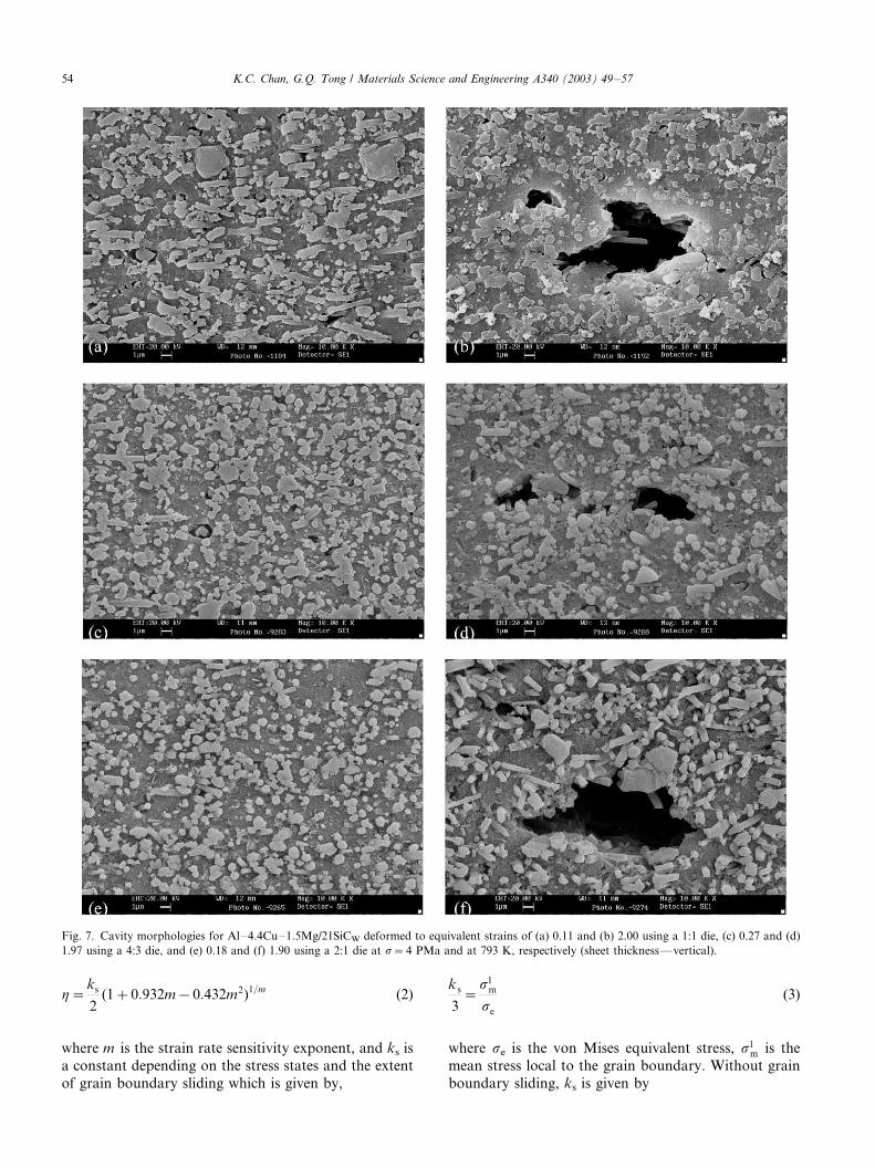
Metallographic examinations of the specimens were
also performed to reveal the morphology and distribu-
tion of cavities. Fig. 7 shows the cavity morphologies of
the specimens deformed to strains of (a) 0.11 and (b)
2.00, (c) 0.27 and (d) 1.97, and (e) 0.18 and (f) 1.90 using
dies different aspect ratios. The results confirm that the
samples deformed to a higher strain level contain larger
cavities. It is found that voids are preferentially nu-
cleated at the matrix/reinforcement interfaces. Large
cavities with diameter of about 5 mm can be observed in
the heavily deformed sample, these cavities are the result
of interlinkage. The interlinkage is probably assisted by
the presence of liquid phases at the reinforcement/matrix
interfaces.
In addition to void nucleating at the interfaces
preferentially, it is reported that the number of cavities
for HSRS Al-MMCs tends to increase with increasing
strain [15,17,18], indicating that this is a continuous void
nucleation and cavity growth process. Whereas, there is
a decrease in the total number of voids per unit volume
or area with increasing strain in Al7475 as a result of
large cavity growth rate and cavity coalescence [29]. It is
considered that void nucleation, which occurs much
more easily at the interface as a result of weak bonding
force between the liquid phase and the solid, is thereason for the difference.
3.3. Forming limits
Fig. 8 shows the samples bulged to failure at the
constant applied stress of 4 MPa and at 793 K using dies
with aspect ratios of (a) 1:1, (b) 4:3 and (d) 2:1. The
experimental limit strains are reported in Fig. 9. It isshown that the major limit strains increase when the
stress ratio decreases. The shape of the curve is different
from that of conventional forming limit curve [22]. This
discrepancy is considered to relate to their differences in
deformation behavior. In conventional sheet metal
forming, strain hardening phenomenon is observed
and it plays an important role in neck formation, while
in superplastic deformation, a high m value representsthe material possesses a high capacity to resistance
necking duration deformation and cavity failure is the
dominant failure mechanism of the material.
4. Discussion
4.1. Influence of stress states on cavity behavior
For strain controlled cavity growth phenomenon, the
parameter of cavity growth rate, h, has been shown
from theoretical considerations as [30]
Table 1
CV0
(%) and h values for superplastic Al-MMCs and aluminum alloys
Materials T (K) /o (s�1) s (MPa) Stress m CV0
h Ref.
Al4.4Cu1.5Mg/21SiCW 793 0.21a �/ UTb 0.35 0.17 1.9 [25]
4c BTb 0.13 2.2 This work
4d BT 0.16 2.0 This work
4e BT 0.15 2.0 This work
Al6061/20Si3N4P 833 2.0 8 UT 0.50 0.27 0.5 [15]
Al7475 788 5.0�10�4 5 UT 0.50 0.01 3.6 [15]
Al6061/20SiCW 873 0.17a �/ UT 0.34 0.28 1.2 [18]
2 BT 0.31 1.6 [18]
Al7475 788 1.17�10�3 UT 0.53 �/ 2.4 [19]
BT �/ 5.6 [19]
Supral 220 733 1.17�10�3 UT 0.55 �/ 2.7 [19]
BT �/ 3.2 [19]
a Experiments conducted at constant displacement rate.b UT and BT means uniaxial and biaxial tension.c Stress ratio 1.0, i.e. die aspect ratio 1:1.d Stress ratio 0.8293, i.e. die aspect ratio 4:3.e Stress ratio 0.6667, i.e. die aspect ratio 2:1.
K.C. Chan, G.Q. Tong / Materials Science and Engineering A340 (2003) 49�/57 53
h�ks
2(1�0:932m�0:432m2)1=m (2)
where m is the strain rate sensitivity exponent, and ks is
a constant depending on the stress states and the extent
of grain boundary sliding which is given by,
ks
3�
s lm
se
(3)
where se is the von Mises equivalent stress, s lm is the
mean stress local to the grain boundary. Without grain
boundary sliding, ks is given by
Fig. 7. Cavity morphologies for Al�/4.4Cu�/1.5Mg/21SiCW deformed to equivalent strains of (a) 0.11 and (b) 2.00 using a 1:1 die, (c) 0.27 and (d)
1.97 using a 4:3 die, and (e) 0.18 and (f) 1.90 using a 2:1 die at s�4 PMa and at 793 K, respectively (sheet thickness*/vertical).
K.C. Chan, G.Q. Tong / Materials Science and Engineering A340 (2003) 49�/5754

ks(0)
3�
slm(0)
se
�s�
m
se
(4)
where slm is the applied (remotely) mean stress. For
freely sliding grains, ks is given by [31]
ks(100)
3�
slm(100)
se
�1
2
�s�
1
se
�s�
m
se
�(5)
/s�1 is the applied (remotely) maximum principle stress.
Since in superplastic deformation, approximately 50% if
the strain is derived directly from grain boundary
sliding/interfacial sliding, Eq. (3) is modified as follows:
ks(50)
3�
slm(50)
se
�1
2
�sl
m(0)
se
�sl
m(100)
se
�
�1
2
�ks(0)
3�
ks(100)
3
��
1
4
�3s�
m
se
�s�
1
se
�(6)
Table 2 illustrated the predicted and experimental
parameters of cavity growth rate for the composite. It is
shown that a higher h value is predicted under
equibiaxial tension than under uniaxial tension which
is in agreement with the experimental findings. Forstrain controlled cavity growth, the local mean stress
plays a major role in cavity growth behavior. Since the
local mean stress is proportional to the overall mean
stress, the h value should be higher under equibiaxial
tension than under uniaxial tension.
4.2. Comparison the experimental forming limits with the
model prediction
Recently, Chow and Chan have developed a limit
strain model based on the M�/K model and the damage
Fig. 8. Al�/4.4Cu�/1.5Mg/21SiCW diaphragms formed using dies with
aspect ratios of (a) 1:1, (b) 4:3 and (c) 2:1 at 793 K and s�4 MPa.
Fig. 9. Comparison between predicted and experimental forming
limits of HSRS Al�/4.4Cu�/1.5Mg/21SiCW assuming f0�0.999.
Table 2
Comparison between predicted and experimental h values under
different stress states
Stress ratio, b 0 0.6667 0.8293 1.0
ks (50) 1.5 2.27 2.29 2.25
Equivalent stress, se s1 0.8819s1 0.9265s1 s1 (s2)
Mean stress, sm s1/3 0.5556s1 0.6098s1 2s1/3
Theoretical h 1.5 2.26 2.28 2.24
Experimental h 1.9 2.0 2.0 2.2
K.C. Chan, G.Q. Tong / Materials Science and Engineering A340 (2003) 49�/57 55

mechanics approach [24] for a superplastic Al5083 alloy.
In this paper, this model is applied to predict the limit
strains of the HSRS composite. In their model, an initial
geometrical defect is assumed to exist and the inhomo-
geneity caused by an inhomogeneous distribution of
cavities is considered. The geometry of the total
inhomogeneity is shown in Fig. 10 and the initial
equivalent M�/K inhomogeneity index, denoted by F0
becomes
F0�f0
(1 � DB0)
(1 � DA0)(7)
where DB0 and DA0 denote the initial volume fraction ofcavities inside (region B) and outside (region A) the
groove respectively, and f0 (�/tB0/tA0) is the initial
inhomogeneity index due to the geometrical defect as
proposed by MK. In order to determine the limit strain,
the following equation has to be solved.ffiffiffiffiffiffiffiffiffiffiffiffiffi1 � B
py[t]mffiffiffiffiffiffiffiffiffiffiffiffiffiffiffiffiffiffiffiffiffiffiffi
1 � By[t] 2p
�f0
� 1 � DB0exp[ht]
1 � DA0exp[hx]exp
�Cx
�gt
0
fA
ffiffiffiffiffiffiffiffiffiffiffiffiffiffiffiffiffiffiffiffi1�By[t]2
q�Dy[t] gdt
�(8)
where
y�doA
doB
; x� oA; t� oB; A�
ffiffiffi3
p
2;
B�3a2
4(1 � a� a2); C�
ffiffiffi3
p
2
1 � affiffiffiffiffiffiffiffiffiffiffiffiffiffiffiffiffiffiffiffiffiffiffiffi1 � a� a2
p ;
D�
ffiffiffi3
p
4
affiffiffiffiffiffiffiffiffiffiffiffiffiffiffiffiffiffiffiffiffiffiffiffi1 � a� a2
p
For a set of values of m , h; DB0, DA0 and f0, Eq. (8)
can be solved numerically by the Runge�/Kutta method
for a given strain ratio, a , under the initial condition,
x�/0, t�/0 and y0, and the latter can be determined by
the following equation
ffiffiffiffiffiffiffiffiffiffiffiffi1�B
pym
0 �f 0
1 � DB0
1 � DA0
ffiffiffiffiffiffiffiffiffiffiffiffiffiffiffiffi1�By2
0
q(9)
The value of y will decrease as x and t increase, and
when the value of y equals to zero, the strain value of x
is regarded as the limit strain.
In this paper, the experimental initial cavity volume
fraction and the cavity growth rate parameters obtainedFig. 10. Geometry of initial inhomogeneity [24].
Fig. 11. Predicted limit strains for Al�/4.4Cu�/1.5Mg/21SiCW for
different f0 and DBo/Dao (dashed line*/experimental results).
K.C. Chan, G.Q. Tong / Materials Science and Engineering A340 (2003) 49�/5756

under different stress states are compared with the
prediction. Fig. 11 shows the predicted limit strains of
the HSRS Al�/4.4Cu�/1.5Mg/21SiCW in biaxial tension
for different f0 and DB0/DA0. f0 is allowed to vary from 1to 0.99 and DB0/DA0 varies from 1 to 2. It is considered
that in practice, f0 ranging from 0.995 to 0.999 is
regarded as reasonable for real aluminum or Al�/
MMC sheets. The values of DBo/DAo which range
from 1 to 2 is also considered to be reasonable in Al-
MMCs as the phenomenon of inhomogeneous distribu-
tion of voids can be easily observed in SEM, though it is
not intended in this paper to determine quantitativelythe DB0/DA0 values by measuring the areas of cavities in
different regions. It is worth to mention that in the
modeling works of Tai [32], the same range has been
used for soft aluminum. The predicted limit strain is also
found to increase with increasing f0 and decrease with
increasing DB0/DA0, and it is successful to predict limit
strains of the MMC sheet under biaxial tension without
assuming any initial geometrical defect. In case of f0
being 1, the best coincidence between predicted strains
and the experimental findings is obtained when DB0/DA0
lies between 1.3 and 1.8. If a small value of initial
geometrical inhomogeneity factor is assumed, the dif-
ference between DB0 and DA0 is reduced in order to
match the predicted limit strains with the experimental
findings. A comparison between the experimental and
theoretical forming limits of the composite is alsoillustrated in Fig. 9. The trend of the prediction is in
good agreement with the experimental findings.
5. Conclusions
In this paper, the thickness distribution, the cavitation
behavior and forming limits of a high-strain-rate super-
plastic Al�/4.4Cu�/1.5Mg/21SiCW sheet were investi-gated under biaxial stress states. For diaphragms
deformed equibiaxially, a good agreement between the
experimental thickness distributions and the predictions
based on the analytical model of Cornfield and Johnson
was observed at the fractional heights (h /h0) ranging
from 0.4 to 1.0. It is considered that the relatively large
discrepancy occurred at the fractional heights lying
between 0 and 0.4 is due to the oversimplified assump-tions used in the analytical model. It is found that the
parameter of cavity growth rate of the composite is
dependent on stress state, and that it increases with
increasing stress ratio, which is consistent with the
theoretical values. The parameter of cavity growth rate
of 2.2 obtained under equibiaxial tension is shown to be
slightly higher than that of 1.9 under uniaxial tension.
Forming limits of high-strain-rate superplastic Al�/
4.4Cu�/1.5Mg/21SiCW at different stress ratios were
predicted based on a plastic damage model recently
developed for superplastic materials [24]. The trend of
the prediction was in good agreement with the experi-
mental findings.
Acknowledgements
This work described in this paper was supported by a
grant from the Research Grant Council of The HongKong Special Administration (project no. PolyU5162/
99E). Support from The Hong Kong Polytechnic
University is also acknowledged.
References
[1] T.G. Nieh, C.A. Henshall, J. Wadsworth, Scripta Metall. 18
(1984) 1405.
[2] T.G. Nieh, P.S. Gilman, J. Wadsworth, Scripta Metall. 19 (1985)
1375.
[3] T.G. Nieh, J. Wadsworth, Scripta Metall. Mater. 32 (1995) 1133.
[4] R.R. Sawtell, C.L. Jensen, Metall. Trans. 21A (1990) 421.
[5] T.G. Nieh, L.M. Hsiung, J. Wadsworth, R. Kaibyshev, Acta
Mater. 46 (1998) 2789.
[6] M. Mabuchi, K. Higashi, Acta Mater. 47 (1999) 1915.
[7] F. Jovane, Int. J. Mech. Sci. 10 (1968) 403.
[8] G.C. Cornfield, R.H. Johnson, Int. J. Mech. Sci. 12 (1970) 479.
[9] C. Hammond, in: N.E. Paton, C.H. Hamilton (Eds.), Superplastic
Forming of Structural Alloys, The Metallurgical Society of
AIME, Warrendale, PA, 1982, p. 131.
[10] H.S. Yang, A.K. Mukherjee, Mater. Sci. Eng. 34 (1992) 283.
[11] J. Pilling, Scripta Metall. 23 (1989) 1375.
[12] G.Q. Tong, K.C. Chan, Scripta Mater. 37 (1997) 1917.
[13] K.C. Chan, G.Q. Tong, L. Gao, J. Mater. Proc. Technol. 74
(1998) 142.
[14] M.I. Yousif, J.L. Duncan, W. Johnson, Int. J. Mech. Sci. 12
(1970) 959.
[15] H. Iwasaki, M. Takeuchi, T. Mori, M. Mabuchi, K. Higashi,
Scripta Metall. Mater. 31 (1994) 255.
[16] K. Higashi, T.G. Nieh, J. Wadsworth, Mater. Sci. Eng. A188
(1994) 167.
[17] S. Wada, M. Mabuchi, K. Higashi, T.G. Langdon, J. Mater. Res.
11 (1996) 1755.
[18] K.C. Chan, G.Q. Tong, Scripta Mater. 38 (1998) 1705.
[19] J. Pilling, N. Ridley, Acta Metall. 34 (1986) 669.
[20] M.W. Mahoney, C.H. Hamilton, A.K. Ghosh, Metall. Trans.
14A (1984) 1593.
[21] X.D. Ding, H.M. Zbib, C.H. Hamilton, A.E. Bayoumi, J. Eng.
Mater. Technol. 119 (1997) 26.
[22] Z. Marciniak, K. Kuczynski, Int. J. Mech. Sci. 9 (1967) 609.
[23] K.C. Chan, G.Q. Tong, Met. Mater. 4 (1998) 280.
[24] K.C. Chan, K.K. Chow, Int. J. Mech. Sci., submitted for
publication.
[25] G.Q. Tong, K.C. Chan, Mater. Sci. Eng. 286 (2000) 218.
[26] G.Q. Tong, K.C. Chan, Mater. Sci. Eng. 325 (2002) 79.
[27] M.J. Stowell, Met. Sci. 14 (1980) 267.
[28] M. Mabuchi, H. Iwasaki, K. Higashi, T.G. Langdon, Mater. Sci.
Technol. 11 (1995) 1295.
[29] J. Pilling, Mater. Sci. Technol. 1 (1989) 461.
[30] B. Budiansky, J.W. Hutchinson, S. Slutsky, in: H.G. Hopkins,
M.J. Sewell (Eds.), Mechanics of Solids, Pergamon Press, Oxford,
1982, p. 13.
[31] J. Pilling, N. Ridley, Res. Mech. 23 (1988) 31.
[32] W.H. Tai, Int. J. Mech. Sci. 30 (1988) 119.
K.C. Chan, G.Q. Tong / Materials Science and Engineering A340 (2003) 49�/57 57