formal network behaviour analysis using model checking … · 2016-03-10 · formal network...
TRANSCRIPT
Formal Network Behaviour Analysis using Model Checking
A THESIS SUBMITTED TO
THE SCIENCE AND ENGINEERING FACULTY
OF QUEENSLAND UNIVERSITY OF TECHNOLOGY
IN FULFILMENT OF THE REQUIREMENTS FOR THE DEGREE OF
MASTERS BY RESEARCH
Douglas Graeme Brown
Science and Engineering Faculty
Queensland University of Technology
2016


QUT Verified Signature

ii

QUT Verified Signature

iv

For my grandfather Graeme Richard Brown, who waited
impatiently for many years, never to see this document’s
completion.
v

vi

Abstract
Networks are the product of two or more inter-connected devices, forming a discrete topology,
each with their own dynamic configuration and asynchronous communicative behaviours. De-
signing and configuring individual network devices to function correctly as per specifications,
such as protocol standards or security policies, has proven a challenge. However, ensuring
composite emergent behaviours resulting from a given topology structure, and dynamic device
configurations also meet their specification is greater still.
Our aim is to provide a rigorous means by which dynamic composite network device be-
haviours can be predicted and examined to ensure they meet a given specification. Using formal
methods of abstraction and a model checker, we have developed a library of common network
devices templates, which can be instantiated with individual configurations, to form a finite-
state model of a given network. Our approach provides the means to express the expected
communicative behaviours of a network, such as an organisational security policy, as temporal
logic safety property predicates, to validate the emergent behaviours of a network.
This thesis’ contribution is divided among four chapters, one for each of the first three
OSI standard’s layers and a final chapter where our approach is used for information-flow
analysis. Each chapter contains a finite-state abstraction of the associated protocols and device
behaviours, including batteries of checks to validate predicted composite behaviours.
The layer one chapter provides an abstraction of the physical network topology. This
includes physical device templates that can be instantiated with individual configurations and
connections to other devices; an abstraction of applicable protocol data units (PDU) for safety
property analysis, and a mechanism to facilitate the exchange of PDUs between device finite-
state models.
The layer two chapter builds upon the foundation of layer one, adding a layer two bridge
vii

device (switch) based on IEEE standard 802.1D-2004 [51], as the first stateful intermediate net-
work device template. The bridge template provides the first dynamic learning and forwarding
behaviour in our abstraction based on physical addressing. In this chapter, we examine Case
Study One where we found an unexpected emergent behaviour when two connected bridges
perform forwarding according to IEEE standard 802.1D-2004. We also provide a revised bridge
specification, whose composite behaviour has been validated using our analysis techniques.
The first layer three chapter is based upon RFC 1812 [4], which is to date the most au-
thoritative specification for layer three logical inter-network forwarding (routing) and filtering
(firewalls). Given the informal and descriptive nature of RFC 1812, our models provide for-
malisms for the routing and filtering behaviours. Exhaustive behavioural checks are performed
and in Case Study Two an organisational security policy from existing literature is examined
using multiple types of device templates.
The second layer three chapter extends our models to facilitate the analysis of network
information-flow based upon Commercial Internet Protocol Security Option (CIPSO) [23], the
defacto standard for network traffic sensitivity labelling, in conjunction with Mandatory Access
Controls. In Case Study Three we use the rigour of the model checker to demonstrate with a
high degree of confidence how an information-flow policy applied to network traffic sensitivity
labels using Mandatory Access Controls can significantly mitigate the risk of network-based
information leakage.
viii

Keywords
Formal Methods, Model Checking, Network, SELinux, Mandatory Access Controls, Information-
flow, Multi-Category Security, CIPSO, Symbolic Analysis Laboratory
ix

x

Acknowledgments
First and foremost, thanks to my supervisors Colin Fidge and Wayne Kelly for the mentoring
they provided throughout my candidature. I’d also like to acknowledge the High Performance
Computing and Enterprise Systems Services teams at QUT who provided much of the compute
and other resources. However, this document only really came to fruition through the unwaver-
ing support of my wife.
xi

xii

Table of Contents
Abstract vii
Keywords ix
Acknowledgments xi
List of Figures xix
List of Tables xxi
1 Introduction 1
1.1 Outline . . . . . . . . . . . . . . . . . . . . . . . . . . . . . . . . . . . . . . 1
1.2 Background . . . . . . . . . . . . . . . . . . . . . . . . . . . . . . . . . . . . 2
1.2.1 Formal Methods . . . . . . . . . . . . . . . . . . . . . . . . . . . . . 2
1.2.2 Computer Network Systems . . . . . . . . . . . . . . . . . . . . . . . 3
1.2.3 Mandatory Access Controls . . . . . . . . . . . . . . . . . . . . . . . 4
1.3 Research Problem . . . . . . . . . . . . . . . . . . . . . . . . . . . . . . . . . 5
1.4 Research Goal . . . . . . . . . . . . . . . . . . . . . . . . . . . . . . . . . . . 6
1.5 Scope . . . . . . . . . . . . . . . . . . . . . . . . . . . . . . . . . . . . . . . 6
1.6 Methodology . . . . . . . . . . . . . . . . . . . . . . . . . . . . . . . . . . . 7
1.7 Statement of Contribution . . . . . . . . . . . . . . . . . . . . . . . . . . . . . 10
2 Related Work 11
2.1 Formal Network Analysis . . . . . . . . . . . . . . . . . . . . . . . . . . . . . 11
xiii

2.2 Information-Flow . . . . . . . . . . . . . . . . . . . . . . . . . . . . . . . . . 13
2.2.1 Operating System Information-Flow . . . . . . . . . . . . . . . . . . . 13
2.2.2 Covert Channels . . . . . . . . . . . . . . . . . . . . . . . . . . . . . 16
2.2.3 Programming Information-Flow . . . . . . . . . . . . . . . . . . . . . 16
2.2.4 Network Information-Flow . . . . . . . . . . . . . . . . . . . . . . . . 18
2.3 Summary . . . . . . . . . . . . . . . . . . . . . . . . . . . . . . . . . . . . . 19
3 Layer One - Physical Network 21
3.1 State Abstraction . . . . . . . . . . . . . . . . . . . . . . . . . . . . . . . . . 21
3.1.1 Topology . . . . . . . . . . . . . . . . . . . . . . . . . . . . . . . . . 22
3.1.2 Media . . . . . . . . . . . . . . . . . . . . . . . . . . . . . . . . . . . 25
3.1.3 Devices . . . . . . . . . . . . . . . . . . . . . . . . . . . . . . . . . . 26
3.2 Behaviour Abstraction . . . . . . . . . . . . . . . . . . . . . . . . . . . . . . 27
3.2.1 Signalling . . . . . . . . . . . . . . . . . . . . . . . . . . . . . . . . . 27
3.2.2 Propagation . . . . . . . . . . . . . . . . . . . . . . . . . . . . . . . . 29
3.3 Analysis . . . . . . . . . . . . . . . . . . . . . . . . . . . . . . . . . . . . . . 30
3.4 Summary . . . . . . . . . . . . . . . . . . . . . . . . . . . . . . . . . . . . . 38
4 Layer Two - Data-link 39
4.1 State Abstraction . . . . . . . . . . . . . . . . . . . . . . . . . . . . . . . . . 40
4.1.1 Physical Addressing . . . . . . . . . . . . . . . . . . . . . . . . . . . 40
4.1.2 Filtering Database . . . . . . . . . . . . . . . . . . . . . . . . . . . . 41
4.2 Behaviour Abstraction . . . . . . . . . . . . . . . . . . . . . . . . . . . . . . 44
4.2.1 Learn . . . . . . . . . . . . . . . . . . . . . . . . . . . . . . . . . . . 45
4.2.2 Unicast . . . . . . . . . . . . . . . . . . . . . . . . . . . . . . . . . . 46
4.2.3 Broadcast . . . . . . . . . . . . . . . . . . . . . . . . . . . . . . . . . 48
4.3 Analysis . . . . . . . . . . . . . . . . . . . . . . . . . . . . . . . . . . . . . . 49
4.4 Case Study One . . . . . . . . . . . . . . . . . . . . . . . . . . . . . . . . . . 58
xiv

4.5 Summary . . . . . . . . . . . . . . . . . . . . . . . . . . . . . . . . . . . . . 63
5 Layer Three - Logical Network 65
5.1 State Abstraction . . . . . . . . . . . . . . . . . . . . . . . . . . . . . . . . . 66
5.1.1 Logical Addressing . . . . . . . . . . . . . . . . . . . . . . . . . . . . 66
5.1.2 Route Table . . . . . . . . . . . . . . . . . . . . . . . . . . . . . . . . 69
5.1.3 ACLs . . . . . . . . . . . . . . . . . . . . . . . . . . . . . . . . . . . 70
5.2 Behaviour Abstraction . . . . . . . . . . . . . . . . . . . . . . . . . . . . . . 72
5.2.1 ARP . . . . . . . . . . . . . . . . . . . . . . . . . . . . . . . . . . . . 72
5.2.2 Local Route . . . . . . . . . . . . . . . . . . . . . . . . . . . . . . . . 77
5.2.3 Next Hop Route . . . . . . . . . . . . . . . . . . . . . . . . . . . . . 78
5.2.4 Default Route . . . . . . . . . . . . . . . . . . . . . . . . . . . . . . . 78
5.2.5 Source Network Check . . . . . . . . . . . . . . . . . . . . . . . . . . 79
5.2.6 Filtering . . . . . . . . . . . . . . . . . . . . . . . . . . . . . . . . . . 81
5.3 Analysis . . . . . . . . . . . . . . . . . . . . . . . . . . . . . . . . . . . . . . 84
5.4 Case Study Two . . . . . . . . . . . . . . . . . . . . . . . . . . . . . . . . . . 98
5.5 Summary . . . . . . . . . . . . . . . . . . . . . . . . . . . . . . . . . . . . . 102
6 Layer Three - Information Security Option 103
6.1 State Abstraction . . . . . . . . . . . . . . . . . . . . . . . . . . . . . . . . . 103
6.1.1 Message Labels . . . . . . . . . . . . . . . . . . . . . . . . . . . . . . 104
6.1.2 Network Labels . . . . . . . . . . . . . . . . . . . . . . . . . . . . . . 105
6.2 Behaviour Abstraction . . . . . . . . . . . . . . . . . . . . . . . . . . . . . . 106
6.2.1 Mandatory Access Control . . . . . . . . . . . . . . . . . . . . . . . . 106
6.2.2 Network Traffic Labelling . . . . . . . . . . . . . . . . . . . . . . . . 106
6.3 Analysis . . . . . . . . . . . . . . . . . . . . . . . . . . . . . . . . . . . . . . 109
6.4 Case Study Three . . . . . . . . . . . . . . . . . . . . . . . . . . . . . . . . . 113
6.4.1 Threat . . . . . . . . . . . . . . . . . . . . . . . . . . . . . . . . . . . 115
xv

6.4.2 Model . . . . . . . . . . . . . . . . . . . . . . . . . . . . . . . . . . . 116
6.4.3 Implementation . . . . . . . . . . . . . . . . . . . . . . . . . . . . . . 119
6.5 Summary . . . . . . . . . . . . . . . . . . . . . . . . . . . . . . . . . . . . . 122
7 Conclusion 123
A Models 125
A.1 network.sal . . . . . . . . . . . . . . . . . . . . . . . . . . . . . . . . . . . . 125
A.2 host.sal . . . . . . . . . . . . . . . . . . . . . . . . . . . . . . . . . . . . . . 127
A.3 repeater.sal . . . . . . . . . . . . . . . . . . . . . . . . . . . . . . . . . . . . 135
A.4 bridge.sal . . . . . . . . . . . . . . . . . . . . . . . . . . . . . . . . . . . . . 136
A.5 router.sal . . . . . . . . . . . . . . . . . . . . . . . . . . . . . . . . . . . . . . 146
A.6 run.sh . . . . . . . . . . . . . . . . . . . . . . . . . . . . . . . . . . . . . . . 164
A.7 topology1.sal . . . . . . . . . . . . . . . . . . . . . . . . . . . . . . . . . . . 172
A.8 topology2.sal . . . . . . . . . . . . . . . . . . . . . . . . . . . . . . . . . . . 173
A.9 topology3a.sal . . . . . . . . . . . . . . . . . . . . . . . . . . . . . . . . . . . 174
A.10 topology3b.sal . . . . . . . . . . . . . . . . . . . . . . . . . . . . . . . . . . . 179
A.11 topology4a.sal . . . . . . . . . . . . . . . . . . . . . . . . . . . . . . . . . . . 183
A.12 topology4b.sal . . . . . . . . . . . . . . . . . . . . . . . . . . . . . . . . . . . 187
A.13 topology5a.sal . . . . . . . . . . . . . . . . . . . . . . . . . . . . . . . . . . . 192
A.14 topology5b.sal . . . . . . . . . . . . . . . . . . . . . . . . . . . . . . . . . . . 201
A.15 topology5c.sal . . . . . . . . . . . . . . . . . . . . . . . . . . . . . . . . . . . 210
A.16 topology6.sal . . . . . . . . . . . . . . . . . . . . . . . . . . . . . . . . . . . 221
A.17 topology7.sal . . . . . . . . . . . . . . . . . . . . . . . . . . . . . . . . . . . 226
A.18 topology8.sal . . . . . . . . . . . . . . . . . . . . . . . . . . . . . . . . . . . 231
B label encodings 237
C Implementation 239
xvi

C.1 Host Configuration . . . . . . . . . . . . . . . . . . . . . . . . . . . . . . . . 239
C.2 Router Configuration . . . . . . . . . . . . . . . . . . . . . . . . . . . . . . . 240
References 249
xvii

xviii

List of Figures
1.1 OSI layers . . . . . . . . . . . . . . . . . . . . . . . . . . . . . . . . . . . . . 7
3.1 Binary matrix topology . . . . . . . . . . . . . . . . . . . . . . . . . . . . . . 23
3.2 Transmission modes . . . . . . . . . . . . . . . . . . . . . . . . . . . . . . . 25
3.3 Topology 1 . . . . . . . . . . . . . . . . . . . . . . . . . . . . . . . . . . . . 31
3.4 Topology 2 . . . . . . . . . . . . . . . . . . . . . . . . . . . . . . . . . . . . 36
4.1 Ethernet Frame PDU . . . . . . . . . . . . . . . . . . . . . . . . . . . . . . . 40
4.2 Message abstraction . . . . . . . . . . . . . . . . . . . . . . . . . . . . . . . . 41
4.3 Bridge architecture . . . . . . . . . . . . . . . . . . . . . . . . . . . . . . . . 45
4.4 Topology 3 . . . . . . . . . . . . . . . . . . . . . . . . . . . . . . . . . . . . 49
4.5 Topology 4 . . . . . . . . . . . . . . . . . . . . . . . . . . . . . . . . . . . . 59
5.1 IPv4 Datagram PDU . . . . . . . . . . . . . . . . . . . . . . . . . . . . . . . 66
5.2 Message abstraction . . . . . . . . . . . . . . . . . . . . . . . . . . . . . . . . 68
5.3 Topology 5 . . . . . . . . . . . . . . . . . . . . . . . . . . . . . . . . . . . . 84
5.4 Topology 6 . . . . . . . . . . . . . . . . . . . . . . . . . . . . . . . . . . . . 99
6.1 Commerical Internet Protocol Security Option PDU . . . . . . . . . . . . . . . 104
6.2 Message abstraction . . . . . . . . . . . . . . . . . . . . . . . . . . . . . . . . 105
6.3 Topology 7 . . . . . . . . . . . . . . . . . . . . . . . . . . . . . . . . . . . . 110
6.4 Topology 8 . . . . . . . . . . . . . . . . . . . . . . . . . . . . . . . . . . . . 114
xix

xx

List of Tables
1.1 Topology Overview . . . . . . . . . . . . . . . . . . . . . . . . . . . . . . . . 9
3.1 Binary matrix . . . . . . . . . . . . . . . . . . . . . . . . . . . . . . . . . . . 23
4.1 Bridge Filtering Database Table . . . . . . . . . . . . . . . . . . . . . . . . . 42
5.1 Local Route Table . . . . . . . . . . . . . . . . . . . . . . . . . . . . . . . . . 69
5.2 Next-hop Route Table . . . . . . . . . . . . . . . . . . . . . . . . . . . . . . . 70
5.3 Default Route Table . . . . . . . . . . . . . . . . . . . . . . . . . . . . . . . . 70
5.4 Firewall Rule Table . . . . . . . . . . . . . . . . . . . . . . . . . . . . . . . . 72
5.5 Topology 5c - RouterA Firewall Rules . . . . . . . . . . . . . . . . . . . . . . 97
5.6 Topology 5c - RouterB Firewall Rules . . . . . . . . . . . . . . . . . . . . . . 98
5.7 Topology 5c - RouterC Firewall Rules . . . . . . . . . . . . . . . . . . . . . . 98
5.8 Topology 6 - SGA Router Firewall Rules . . . . . . . . . . . . . . . . . . . . . 99
5.9 Topology 6 - SGB Router Firewall Rules . . . . . . . . . . . . . . . . . . . . . 100
6.1 Topology 8 - Permissible Inter-Network Flows . . . . . . . . . . . . . . . . . . 114
6.2 Topology 8 - Permissible Inter-Network Process Flows . . . . . . . . . . . . . 115
6.3 Case Study Three - Experimental Results . . . . . . . . . . . . . . . . . . . . 121
xxi

xxii

Chapter 1
Introduction
“With networking being fundamentally important to all aspects of life including
government, defence, industry, finance, etc., networks are in dire need of provably
correct mechanisms” [47]
In an age where electronic communications dominate, careful design alone is not sufficient
to ensure network equipment behaves in the intended fashion. Techniques such as simulation are
useful for examining expected behaviours, but are only able to examine one scenerio at a time
and thus not well suited to the prediction of unexpected behaviours. It is for this reason that
the communicative behaviours of security-critical networks require formal analysis to verify
their behavioural properties, especially the absence of unexpected and potentially hazardous
emergent characteristics.
1.1 Outline
This introductory chapter provides a brief background to the technologies used in our work and
an overview of the research itself, followed by related work and four chapters of contribution.
Each such chapter provides an abstraction of one of the first three Open Systems Interconnection
(OSI) model (ISO/IEC 7498-1) [1] layers, with the fourth being an extension of layer three to
support information-flow. Structuring this document based on OSI layers is advantageous, as
the framework is designed to facilitate the independent analysis of one another. Each OSI
chapter is partitioned into three sections: an abstraction of the layer’s state; an abstraction of
the layer’s behaviour; a discussion and finally a case study (except layer one). Each subsection
1

2 CHAPTER 1. INTRODUCTION
within the state and behaviour abstraction sections discusses a specific aspect of the layer.
1.2 Background
This section provides a brief introduction to the three main fields of our research: Formal
Methods, Networking and Information-Flow. Formal methods is the application of discrete
mathematics to system behaviour analysis and takes various forms, however all formal eval-
uation approaches provide a degree of rigour beyond other informal testing methodologies.
The second field covered here is computer network systems and the third, Mandatory Access
Controls.
1.2.1 Formal Methods
“Simulation techniques are inefficient in catching “what if” cases that occur rarely
in the system. . . The use of formal methods is better suited for checking these
situations to uncover hidden problems.” [52]
Theorem proving is the most rigorous formal method of analysis which can provide abso-
lute1 proof of properties, however this process must be performed manually, making it slow,
expensive and only useful for small applications. Alternatively, another type of formal analysis,
model checking, can be fully automated because it proves the properties of finite-state repre-
sentations of systems, not the systems themselves. A finite-state abstraction is a representation
of a system whose variables have defined bounds, that is, unlike real systems which have either
extremely large or infinite possible states, a finite-state model has a quantifiable number of
variable permutations. Finite-state models always have a starting set of state variable values
(either initialised with a value or non-deterministically chosen), which are then changed in
some way due to a transition guard’s predicate (logical expression) evaluating to true, causing
it to “fire” and change the state of one or more variables (N.B. If more than one transitions’
guard evaluates to true, one of the transitions is non-deterministically chosen). This action of
transitions firing and changing the model’s state is how behaviours are represented in finite-state
automata and can be automatically processed by a model checker against a given property.
1Holds under all circumstances.

1.2. BACKGROUND 3
Model checking is however, far from simple. Ensuring a finite-state model faithfully rep-
resents the aspects of the system being evaluated is essential to producing valid proofs. The
greater the degree of detail included in the abstraction, the more likely the model’s behaviour
will accurately mimic that of the real system, leading to better evaluation outcomes. Conversely,
the more detail included, the greater the number of states that the model checker must examine
to determine if the model holds the prescribed proof properties. Should a model have too
large a state, also known as “state-space explosion”, analysis becomes impractical, as the
computational resources required to examine every possible permutation are too great. In this
way, abstraction is in one sense an art that requires skill to develop a representation that has just
sufficient detail to successfully predict the behaviour of a system, but not so much, such that
analysis is infeasible.
There are three types of properties a model checker can evaluate: safety, liveness and
fairness. Safety proofs are used to ensure a system can never reach a “bad” state; liveness
proofs are used to ensure a system always reaches a “good” state and fairness proofs are used
to ensure that when a system is faced with a non-deterministic choice, it will at some point take
all the valid paths. It’s important to note that in our work here, we are interested exclusively
in safety properties. These properties are expressed using temporal logic predicates2, for which
there are several forms, such as: Linear Temporal Logic (LTL) and Computational Tree Logic
(CTL). In our research here we have used LTL.
1.2.2 Computer Network Systems
The goal of computer networks is to provide a means by which distributed systems may com-
municate. This may appear superficially simple, however there are a significant number of
protocols required to produce end-to-end communication between devices in modern networks,
especially in an inter-network as large and disparate as that of the Internet. In contrast, early
electronic network systems such as the telegraph had a single protocol which dictated how
messages were produced and propagated.
An abstract framework known as the Open Systems Interconnection (OSI) model (ISO/IEC
7498-1) [1] was first published in 1984 by the International Organization for Standardization
2Temporal logic combines Boolean operators (AND, OR, XOR, NOT, etc.) with assertions about the sequenceof states (always, next, eventually, etc.).

4 CHAPTER 1. INTRODUCTION
to simplify protocol interactions and encourage better interoperability. This was achieved
by separating out the tasks required for networked communications into seven independent
layers. The intention of the OSI model was that it be followed by those designing protocols.
Unfortunately, the most common group of network protocols in use today, the TCP/IP protocol
suite, does not strictly follow the OSI architecture. This thesis is organised based on the first
three layers of the OSI model, which are responsible for the production and propagation of
discrete packets of information between devices across a computer network, but our models
themselves are based upon Ethernet standards and the TCP/IP protocol suite.
1.2.3 Mandatory Access Controls
For many decades, the Defence and Intelligence community has used so called “Trusted Sys-
tems”, which assign sensitivities and categories to the information they handle. The dissem-
ination of information is then restricted by an operating system protection [34] mechanism
known as a Mandatory Access Control, according to an information-flow policy. Trusted
Systems typically use a Multi-Level Security (MLS) policy based on Bell-LaPadula [9], how-
ever MLS is widely acknowledged as being inappropriate for corporate use in the way it re-
stricts information-flow based on military sensitivities and is sometimes incompatible with
commercial-off-the-shelf software3.
A Mandatory Access Control examines systems calls, also known as access vectors, and
according to a given access control policy, can log then deny or allow the attempt. MACs deny
all access vectors, unless explicitly allowed by a policy, which is prescribed by the adminis-
trator [56]. Mandatory Access Controls consider everything in a system as either a subject or
an object, where a subject is an active party attempting to manipulate an object (passive party),
using an access vector. Subjects are typically users and processes. Objects are commonly files
or other resources. Access vectors depend on the class of the object being accessed, however
in the case of a file, access vectors include: open, read, write, append. All subjects and objects
are labelled by the system according to an administratively set labelling policy. A label may
comprise values such as: a role, domain/type and information classification. These values are
used in policy rules to prescribe permitted access.
3Unmodified third-party software occasionally does not function on MLS systems due to a lack of support foraccess vector-based information-flow restrictions.

1.3. RESEARCH PROBLEM 5
Mandatory Access Controls that support information-flow policies, such as Multi-Level
Security (MLS), have a hierarchy of information sensitivities and a set of categories. MLS
refers to a confidentiality protection policy based on Bell-LaPadula [9] that restricts subjects’
access to objects according to the relationship between the subject’s level of clearance and the
object’s classification. Bell-LaPadula’s first rule asserts that a subject may not read an object that
is of a higher classification. Known as the “simple security policy” or “no read up”. The second
is known as the “confinement property”, which prohibits a subject from writing to objects of
a lower classification, also known as “no write down”. In Chapter 6 we model the use of an
information-flow policy based on MLS, known as Multi-Category Security (MCS).
1.3 Research Problem
The complex dynamic behaviours of computer networks are the result of multiple layers of
inter-dependent interacting protocols. The behaviour of network devices are determined by the
physical properties of a network (connections between devices forming a discrete topology),
behavioural characteristics of a device (programmed by the manufacturer according to a given
set of protocol specifications) and their administratively set and dynamically learnt configu-
rations. Together these variables make evaluating the behaviour of an given network device a
complex task. It is however considerably more challenging to validate the composite behaviours
of networking devices to ensure they meet a given specification, such as a protocol standard or
organisational security policy.
The dynamic nature of networks is a product of these substantial number of permutations
and has implications for the ease with which such complex systems may be analysed. Testing
methodologies and tools (such as simulation) are commonly used for the verification of large
complex systems, as the state-space is prohibitively large for more rigorous analysis using
techniques such as model checking. However, discovering behavioural flaws that are unlikely
to be uncovered with conventional techniques is especially important for networks with high-
security requirements.

6 CHAPTER 1. INTRODUCTION
1.4 Research Goal
Our goal is to produce a modelling technique for accurately predicting compositional commu-
nicative network device behaviours, such that rigorous analysis may be performed to ensure
their emergent properties conform to the confidentiality and integrity security requirements
of a given specification under all circumstances. For analysis at this depth to be possible,
the scale at which our technique is applied must be reduced to a representative set of devices
with abstracted behaviours and configurations that nonetheless meet the essential characteristics
of the real system, such that any analysis performed yields results that accurately reflect the
relevant behaviours of the real system under consideration.
1.5 Scope
Our interest here is exclusively with the message flow related behavioural characteristics of
network systems, principally how messages are transformed and propagate across a network,
excluding all timing, capacity and other performance related properties of networks such as
timing covert channels. In this way, our models are suitable for the examination of safety
properties, such as “can a message from A ever reach B” (i.e., confidentiality) or “can a message
with these properties ever reach B” (i.e., integrity), rather than liveness properties, such as
“will a message from A eventually reach B” or “does a message from A always reach B” (i.e.,
availability).
Our research encompasses the first three layers of the OSI standard for networking [1], as
seen in Figure 1.1. This includes the physical network, physical network addressing (data-
link) and logical network addressing. Although fourth layer addressing is commonly used
for traffic filtering, addressing at layer four is designed for inter-process communication and
outside the scope of our research. We also do not consider various forms of tunnelling and
encapsulation, such as VLANs, vxLANS, and VPN. Although static layer three switching (also
known as routing) is included in our models, the considerably more complex behaviours of
dynamic routing protocols are not included within our research scope.

1.6. METHODOLOGY 7
Layer Three - Network
Layer Two - Data-link
Layer One - Physical
Layer Six - Presentation
Layer Seven - Application
Layer Five - Session
Layer Four - Transport
Out
of
scop
eFigure 1.1: OSI layers
1.6 Methodology
Our research was conducted by performing the following for the OSI model’s [1] first three
layers:
1. Find the most authoritative specification documentation (standard or de facto standard)
for each applicable device type and protocol of the layer under investigation.
2. Summarise behaviours and state properties from the document, removing anything that is
related to liveness or does not have a bearing on message flow.
3. Formalise behaviours and state.
4. Express as a finite-state (bounded variable and guarded transition) model.
5. Design a topology and configuration to examine all possible composite behaviours.
6. Run model checker against battery of checks.
7. Examine results; if behavioural abnormalities are evident, return to step 4.
8. Develop a validation using real-world configurations.

8 CHAPTER 1. INTRODUCTION
Given our stated research problem and goal, we decided to use the Symbolic Analysis
Laboratory (SAL)4 framework for our research. SAL provides a model and property speci-
fication language in addition to several verification tools, notably symbolic and bounded model
checkers. SAL’s focus on providing the ability to analyse the properties of concurrent systems
at scale was key in our choice over other similar verification tool sets such as SPIN using
Promela. SAL is able to provide counter-examples5 for properties expressed as Linear Temporal
Logic (LTL) predicates, but not Computational Tree Logic (CTL). This too was important in
our decision to choose SAL, as the safety properties we analyse are best described with LTL’s
always operator.
In our research we modelled 11 variations of four classes of device: a hub/repeater, bridge,
router and host. This range of devices was chosen to enable the evaluation of layer 1–3
behaviours. For each class of device, we have created one or more templates that can be
instantiated with configuration into a network to form a topology model. Multiple templates
for a given type of device were produced where variations upon the behaviour of a device were
required. For example, in Chapter 4 when we discovered a flaw in the protocol governing bridge
message processing behaviour, we created a new device template to show how the behavioural
flaw could be rectified.
The definitions of how protocol data units (PDUs)6 are represented in SAL were placed in
the network.sal file, and imported into all device templates and topology files as a common
library. We have a dozen topology files, with each representing an experiment, instantiating the
devices with their configuration and defining the topology.
The topology files also contain the check predicates for each experiment, which we have
named using the following convention:
group#_test#_<depth>_<expected_result>
We implemented this naming convention to provide the means by which checks could be
automatically run and their output analysed. The run.sh script, seen in Appendix A.6, uses
4http://sal.csl.sri.com5A series of state transitions that lead to the specified property not holding.6For simplicity, we typically refer to PDUs as simply “messages” throughout the text.

1.6. METHODOLOGY 9
Table 1.1: Topology Overview
Topology Purposetopology1 Point-to-Pointtopology2 Repeatertopology3a IEEE Bridgetopology3b Proposed Bridgetopology4a Case Study One (IEEE Bridge)topology4b Case Study One (Proposed Bridge)topology5a Routing with Source Network Checktopology5b Routing without Source Network Checktopology5c Firewalltopology6 Case Study Twotopology7 Network Information-Flowtopology8 Case Study Three
the depth value to determine which model checker should be used for the check.7 As a result,
the script can be used to automatically run all the checks for an experiment; or if necesssary all
263 checks in the dozen experiments.
Once the check has run, the script then provides a summary of the results, indicating whether
or not the expected result was returned8. The full output of each check and its associated
summary are written to the files:
<topology_name>-<check_name>-<version>.output
summary-<version>
where version is the current git version. In this way, we are able to compare any historical
version of the model with its associated check outcomes.
For the sake of efficiency, checks designed to show a certain behaviour by providing counter-
examples (i.e., those with an expected result of ‘false’), are given the minimum depth value
7The SAL framework has both a symbolic and bounded model checker. The symbolic model checker performsa complete state-space exploration when determining if a model holds a given property, whereas the boundedmodel checker only explores the state-space to the depth provided by the practitioner.
8The results for each check still require manual examination; the summary merely provides the means ofdetecting obvious errors.

10 CHAPTER 1. INTRODUCTION
required so as to reduce the compute resource and therefore time required to run the check. All
263 checks provided in this thesis have been run, providing the result expected at the depth
specified in their name. Where possible, we have performed a full (unlimited depth) state-space
exploration for checks not expected to return a counter-example. However, in some of the later
topologies with very large state-spaces we determined the depth to which we can be confident
a check has verified the expected behaviour, and limited exploration to that depth.
1.7 Statement of Contribution
This thesis provides the following contributions to knowledge:
1. A method for representing independent stateful network devices as parameterised instan-
tiable finite-state automata templates and their physical connections
2. A finite-state abstraction of nested network protocol data units (PDU) and a means to
represent their propagation for safety property analysis
3. An approach to faithfully represent stateful asynchronous protocol decisions as predicate-
guarded transitions using non-deterministic choice
4. A technique for examining the behavioural safety properties of a network against a given
specification using temporal logic
5. The application of our models to practical case studies, including one which revealed
a flaw in an IEEE standard, and from which we developed a solution to the problem
identified
Chapter 2
Related Work
Our research is principally in the area of formal network analysis, however our models also
provide the means to analyse distributed information-flow in computer networks. In this chapter
we note a range of related works from both areas and discuss the most pertinent literature in
relation to our contribution.
2.1 Formal Network Analysis
“Even well administered networks are vulnerable to attacks due to the security
ramifications of offering a variety of combined services. That is, services that are
secure when offered in isolation nonetheless provide an attacker with a vulnerability
to exploit when offered simultaneously.” [49]
Over decades formal methods have been to used to evaluate various aspects of networking.
Formal network reachability and firewall analysis has an especially large body of research,
mainly detecting conflicts in policies and misconfigurations [59, 17, 33, 60, 36, 28, 18, 10, 5],
some of which considers reachability as an emergent property of networks when dynamic rout-
ing is used in conjunction with distributed firewalls [15, 43]. Kazemian et al. used formalisms in
conjunction with parsed router configurations to statically find misconfigurations [32]. Our re-
search encompasses reachability analysis and our models are also capable of analysing conflicts
in distributed security policies such as firewalls, however our models are capable of predicting
the safety properties of a number of network behaviours.
11

12 CHAPTER 2. RELATED WORK
“While in this example all possible states of network behavior can be easily enu-
merated, a real network consisting of tens of routers poses a real challenge to
prove that the network ensures designed security, safety and availability of network
resources.” [52]
Formal methods have also been applied to network vulnerability analysis in a number of
publications. [24, 49, 52, 53]. These approaches demonstrate how the relationship between a
given network and vulnerabilities in services they run can be formally analysed, however the
merit of these approaches is debatable given they are only capable of predicting known attacks.
Xiaoxiao and Jun [58] used model checking with “entities” (similar to our network device
templates) to analyse liveness properties, however their approach is much less an abstraction
than an object-oriented model of a router. The authors do not provide details of how the
model was produced nor do they provide sufficient evidence in the form of case studies to
demonstrate its use. On the other hand, Al-Shaer et al. [3] used model checking in a very
similar fashion to our approach. Their research has a number of parallels with ours in the
way they modelled the transformation and propagation of network traffic. In the same way
we do, Al-Shaer et al. encoded device behaviours into message processing transition guards as
metadata property predicates. As with the other research noted, however, their models focus
exclusively on firewalls (and IPSec) at layers 3/4. In addition, their device models are stateless
and mostly deterministic. As a result, their approach cannot represent complex multi-message
dynamic behaviours, nor interactions between protocols at different layers of the network stack.
Recently, El-Khoury et al. [16] used Coloured Petri Nets to produce nine basic “command”
building blocks, prescribing how state is transformed by a given protocol. Their work references
Al-Shaer et al.’s work to a great extent and their case studies also focus heavily upon firewalls
and IPSec at layers 3/4. In a similar way to our work, nested attribute-value couples are used
for both message protocol data unit headers and device configuration state. El-Khoury et al.’s
work bears several remarkable similarities to ours but where we have modelled layers 1–3, they
have modelled layers 3–4 using a different specification language/tools.
A significant body of work exists describing the communicative behaviours of systems
using process algebras, such as Communicating Sequential Processes (CSP), for the purposes
of security protocol analysis. The most notable example is Gavin Lowe’s seminal paper in
1996 [39], which used CSP and the FDR model checker to discover a 17 year old weakness [6]

2.2. INFORMATION-FLOW 13
in the Needham-Schroeder protocol [44] that underpins Kerberos1. Publications from and
using the tools of the Automated Validation of Internet Security Protocols and Applications
(AVISPA) Project [2] also fall into this category of work, as their contributions also focus on the
verification of higher-layer protocols using formal specifications and model checkers tailored
to the examination of cryptographic problems that assume a Dolev-Yao model of adversary
capabilities2.
In our opinion, applying formal methods solely to the analysis of network reachability, fire-
walls, vulnerability analysis, cryptographic protocols, or any other specific aspect of network-
ing, does not take into consideration the broader challenges of understanding how a number
of protocols and configurations interact to provide network communications. Furthermore, the
level of abstraction chosen for formalisms often risks neglecting important details of the system
being represented. For this reason, our research focuses on network behaviour, with aspects
such as inter-policy firewall conflicts being emergent properties that are able to be considered
in the full context they are produced.
2.2 Information-Flow
In this section we briefly cover contributions from pertinent literature related to distributed
information-flow.
2.2.1 Operating System Information-Flow
Multi-Level Security (MLS) refers to security frameworks that take into consideration varying
degrees of sensitivity with respect to the traditional security goals of confidentiality and integrity
where objects are assigned a classification level and access to objects is restricted based on the
clearance of a subject and the applicable security policy.
In the late 1960s, due to the expense of infrastructure, computing was centralised to main-
frames and time-sharing systems3 were beginning to be used, but difficulties were raised in the
1Kerberos is an authentication protocol widely used in commercial applications.2The Dolev-Yao model of a network abstracts the lower layers we model here and assumes an adversary has
complete control over communication channels, so that the properties of a security protocol under examination canbe shown to hold under those conditions.
3Time sharing is a form of computing that supports the sharing of computing resources among multiplesimultaneous users and the ability to execute concurrent processes.

14 CHAPTER 2. RELATED WORK
segregation of information based on security clearance [7]. David Bell and Leonard LaPadula
began research in 1972 to produce a mathematically formal model of Multi-Level Security
(MLS) in relation to Multics4. The model they went on to produce is still used today as the
cornerstone of Multi-Level Security in research and military applications. The Bell-LaPadula
security policy model provides a set of formalised rules that govern information-flow in a multi-
level setting with respect to the traditional security goal of confidentiality.
The first Bell-LaPadula mandatory access control rule states that a subject may not read an
object that is of a higher classification [8], also known as the simple security policy or no read
up. The second is known as the confinement property, which prohibits a subject to write to
objects of a lower classification [8], also known as no write down.
In later publications, Bell-LaPadula add further elements to their model in order to accom-
modate the implementation of their model in a Multics prototype [9]. These include the trusted
subject5, who is not bound by the confinement property and the weak tranquillity principle,
which incorporates the notion of need to know, by stating that a classification may change
providing it does not violate the security policy.
The Bell-LaPadula model is limited in scope, in that it only considers the confidentiality
security requirement. In 1975, a year before Bell and LaPadula’s final publication developing
Multi-Level Security, Kenneth Biba (also from Mitre Corp.) published his own model which
aimed to address the integrity limitations of Bell and LaPadula’s work. Biba’s mandatory access
control rules were the inverse of Bell-LaPadula in that subjects were not allowed to read an
object of a lower classification and not allowed to write to an object of higher classification [11].
Just as with Multi-Level Security, Biba model-based policies are still available in modern oper-
ating systems today; however in this thesis we propose an approach to mitigate data exfiltration
and as such, confidentiality provided by the Bell-LaPadula model has greater importance.
Information security standardisation began in the 1980s with the publication of the Amer-
ican Defence Department’s Rainbow Series of security standards. The Rainbow Series is a
collection of 37 books of various colours that cover a variety of topics related to information
security in systems which implement Multi-Level Security, also known as trusted systems.
However, by that time, implementing Multi-Level Security policies (i.e. Bell-LaPadula) in
4Multics is a precursor to the UNIX family of multiuser computer operating systems.5The trusted subject in modern trusted systems is commonly a privileged role assigned to users rather than one
“superuser” such as root.

2.2. INFORMATION-FLOW 15
trusted system software was already well researched [31, 30, 57].
The Rainbow Book series in the 1990s became the basis of an international standard known
as the Common Criteria (CC). This document is now used to assess information technology
products to ensure they meet a minimum set of criteria, for the level at which they are being
assessed, to determine if a product possesses the required security properties. Seven Evaluation
Assurance Levels (EAL) are defined in the Common Criteria, with each successive level having
greater and more stringent security property requirements. EAL5 and above require the use of
formal methods in documenting a product for evaluation [37].
HiStar is a special-purpose operating system built with fine-grained information-flow con-
trols. Zeldovich’s thesis in 2007 [61] that introduced HiStar erroneously asserts: “Building
secure applications from untrusted code requires safely executing arbitrary code on sensitive
data, something that no current operating system provides satisfactory mechanisms for’’. On
the contrary, the Open Source Mandatory Access Control SELinux, applies the principle of least
privilege with Domain-Type Enforcement, Role-based Access and Information-Flow Controls
(Multi-Level and Multi-Category Security policies certified against the Common Criteria to
EAL4+6 for use as a trusted system). SELinux was released by the NSA in 2001 [38] and is
now widely used in both defence and civilian settings and our research here. As with HiStar,
SELinux has no notion of a superuser, nor is any executing process other than the kernel
“trusted”.
Information-flow control in operating systems has been the subject of decades of research.
The trusted systems that were subsequently produced as a result of that research may once have
been thought of as only practical, necessary and accessible to the defence community. On the
other hand, with the relatively recent emergence of commercially-supported information-flow
controls in general-purpose operating systems and an increasing threat of corporate espionage,
it could be argued that operating system information-flow controls are now both accessible and
neccessary in the corporate sector. Our approach of applying information-flow restrictions using
only categories demonstrates how these technologies can also be practical.
6http://www.commoncriteriaportal.org/products/

16 CHAPTER 2. RELATED WORK
2.2.2 Covert Channels
The channels by which information flows are classed as being either overt or covet in informa-
tion security evaluations. Channels that carry information for which they are designed, such
as a protocol’s payload, are considered overt. Lampson [35] first suggested the concept of a
covert channel in 1973 with respect to information flows that violate Bell-LaPadula’s no write
down confinement property in trusted systems. In 1993, the United State’s National Computer
Security Center published NCSC-TG-030, also known as the Light Pink Book, dedicated to the
analysis of covert channels in trusted systems.
A covert channel is an undisclosed channel of communication that operates over an existing
benign overt channel. For this reason a covert channel cannot exist without an overt carrier
channel. Covert channel information flows are of particular concern, as they can be used to
circumvent information-flow policies. Covert channels are measured in terms of the speed
and capacity at which they are capable of transmitting information. Current literature [50]
identifies six forms of covert channel: payload, metadata, timed, termination, probabilistic,
resource exhaustion and power. Several of these forms could be used together or as Jankowski,
et al.’s research [27] shows, several covert channels of the same type may be used together to
prevent detection.
Our research is limited to the evaluation of overt channels, however, the risk posed by
covert channels in security-critical network environments reinforces the need to understand the
circumstances under which overt channels can exist between network devices, as the absence
of such an overt channel also guarantees covert channels cannot exist. In this way, our work
contributes to the mitigation of covert channels in security-critical networks through a better
understanding of overt channels.
2.2.3 Programming Information-Flow
In 1982, Goguen-Meseguer’s paper, “Security Policies and Security Models”, introduced the
non-interference property, the goal of which is to ensure subjects are independent in terms of
the outputs they receive [19]. In a Multi-Level Security system implementing Bell-LaPadula’s
simple security policy, overt read up channels may be prohibited, however, if individual pieces
of software do not satisfy non-interference, they may allow information to be leaked or inferred
2.2. INFORMATION-FLOW 17
about an object of higher classification to a lower clearance subject.
Since Goguen-Meseguer’s seminal work on non-interference, the scope of this field of re-
search has broadened greatly. Much work has been done in the area of information-flow analysis
in order to produce techniques for the design and analysis of code to check non-interference
properties [21]. Confirming code satisfies non-interference can be difficult, as software often
has infinite possible inputs, and thus static and dynamic approaches in conjunction with formal
verification techniques are required for rigorous evaluation [40]. Support for information-flow
controls in programming languages are under active development. These “security-typed”
languages provide support for the built-in multi-level labelling of variables either at compile
or run-time so the non-interference property can be enforced. Compile-time static analysis
has proven very useful [46], however, if dynamic analysis techniques are used at run-time,
where two variables’ values might be used in the production of a third value, then that third
value will be labelled at the level of the highest of the source variables. This is designed to
prevent information from flowing “down”, but can lead to label-creep, where the classification
of information increases as it is accessed by higher clearance subjects. As a result, dynamic
information-flow controls are too restrictive for most applications [50].
“Any variable or data structure must be assumed to contain confidential informa-
tion if it might have been modified within the statement–or inside any function
called from it. Determining which modifications are possible requires evaluating
all possible execution paths of the program, which is not feasible at run time.” [50]
Much peripheral work has been done with programming languages to control information-
flow, however Cheng’s programming framework Aeolus [12] is particularly relevant here as
it focuses on distributed inter-process communication. Interestingly, Cheng uses the same
information-flow policy as our work, however there are several important differences. Aeolus’
primary goal is to mitigate the risk of information leakage as a result of programmer error.
Furthermore, Cheng’s approach requires all interacting processes to be written with the Aeolus
framework, whereas category-labelled subjects are handled by the operating system in our work,
transparent to the application.
CLAMP [45] provides a means by which web services can be hardened to restrict information-
flow, with the goal of preventing information theft. Their approach requires minimal changes

18 CHAPTER 2. RELATED WORK
to existing systems, however the scope of their work is operating system specific and does not
extend to other services, which is in contrast to our approach that is operating system, service
and enforcement mechanism agnostic.
2.2.4 Network Information-Flow
Lu and Sundareshan’s 1990 paper, “A Model for Multilevel Security in Computer Networks” [41],
which built upon Walker’s [55] notion of a Trusted Network Base, provided a formal model
for the application of information-flow policies to network traffic using Mandatory Access
Controls (MAC). Although their work was written at a time when the need for commercial
information security was not fully appreciated, they did however recognise the need for network
information-flow controls.
In 1998, Chitturi’s thesis [13] demonstrated how a model such as Lu and Sundareshan’s
could be implemented. Chitturi modified FreeBSD’s TCP/IP stack to integrate MAC policy
enforcement and demonstrated how it could be used for applying a Multi-Level Security policy
to network traffic.
Jaeger et al. [26] provided encrypted labelled networking by extending IPSec. Their work
is now integrated into the Linux kernel and brought with it the ability to use the SELinux MAC
to enforce information-flow policies on network traffic flows.
Kamath [29] argued that in a virtualised environment, the hypervisor7 could provide secure
communication channels between guest operating systems and used SELinux to create a Trusted
Network Base. However, Kamath’s goal isn’t clearly articulated, furthermore his contribution is
limited in application and fails to identify or address the broader issues of network information-
flow.
Possibly the most important literature in relation to our work here is Zeldovitch et al.’s
paper, “Securing Distributed Systems with Information Flow Control” [62], which built upon
their HiStar work mentioned earlier, by providing a framework called DStar, for the extension
of HiStar-based operating system information-flow controls to distributed systems. Several
parallels can be drawn between their work and ours here. In a similar fashion to our work,
DStar uses category sets assigned to processes which are in turn used to label network traffic
7A hypervisor is software which is used to run multiple instances of operating systems on the same hardware,also known as guest “virtual” machines.

2.3. SUMMARY 19
for the purpose of filtering.
The primary point of differentiation between our work and that of DStar is in how category
labels are managed. Their paper notes the untrustworthy nature of programs as the motivating
factor for applying information-flow controls to network traffic. However, this argument is
undermined by their suggested framework, which places the authority to assign category labels
and therefore control information-flow, on the processes themselves, rather than a trusted actor.
As a result, untrustworthy code can undermine the information-flow mechanism. For this
reason, we believe a true distributed Mandatory Access Control is required, where labels are
administratively assigned.
Furthermore, a fundamental difficulty with distributed systems is that of trust. Our approach
overlooks this by focusing on corporate networks, where central administration is assumed,
whereas DStar claims to be applicable to all network environments (including the Internet), as
it has a decentralised trust model. This is not achieved via a third-party, rather it is done on an
ad-hoc basis, with the authors claiming the motivation for which is to prevent innovation from
being stifled and security reduced – claims that are not substantiated.
Unlike our work, one of the goals of DStar is to mitigate network covert channels. To
achieve this however, their proxy-type daemon required on each host must be stateless and
so connection-oriented “reliable” network protocols, such as TCP cannot be used. Given our
goal is to provide information-flow control over corporate networks, where the use of TCP
is widespread, we consider this limitation too great. DStar claims their use of only stateless
network protocols avoids covert channels, but fails to provide sufficient proof in the form of
formal analysis to support their assertions.
Rather than providing another policy enforcement mechanism, as is the case with the related
works cited in this section, our contribution demonstrates how to apply the existing mechanisms
developed from literature of decades past, to a current and increasing issue in the corporate
sector.
2.3 Summary
As has been shown in this chapter, although many varied aspects of networking have been evalu-
ated in the literature using formal techniques, little attention has been given to the correctness of
20 CHAPTER 2. RELATED WORK
interactions between layers of protocols, particularly OSI layers 1–3. Given these lower layer’s
composite properties have the potential to jeopardise higher-layer assumptions, our work here
focuses on providing the means to understand those lower-layer behaviours with formal rigour.
We have also discussed works in relation to distributed information-flow. Reviewing these
works demonstrates a lack of practical techniques in the literature for mitigating modern cor-
porate network information leakage. For industry to adopt new technologies and administrative
practices in the mitigation of information leakage, they must be commercially viable. We
believe our approach meets this need and by building upon our formal network behaviour work,
we comprehensively show the validity of our proposed approach.

Chapter 3
Layer One - Physical Network
In this chapter we consider layer one of the Open Systems Interconnection (OSI) model (ISO/IEC
7498-1) [1], which governs the physical characteristics of a network. As with the other OSI
layer chapters, this chapter is organised into three main sections: state abstraction, behaviour
abstraction and analysis.
The topology of a network is defined by the physical connections between devices that
are used to facilitate communication using signals. A network’s physical topology determines
the direct communication devices may have with one another. Naturally, a network’s physical
topology can change, however at any given point in time the ability for devices to communicate
with one another is restricted by their current physical connections. A device may indirectly
communicate with another device with via others, however this requires the cooperation inter-
mediary devices to propagate a signal.
In modelling the behaviour of OSI layer one, we need to produce a finite-state abstraction of
the devices, the physical connections between them and a mechanism by which they can send
and receive messages. There is however, nothing simple about abstracting these properties.
In this chapter, we look at various approaches considered and the rationale behind abstraction
choices made, including a number of checks to validate behavioural characteristics.
3.1 State Abstraction
This section discusses each aspect of this layer’s state and how they were represented as finite-
state bounded variables.
21

22 CHAPTER 3. LAYER ONE - PHYSICAL NETWORK
3.1.1 Topology
Initially we considered whether or not a network system should be represented as one large
finite-state model. In the modelling of discrete components, that approach may be used, how-
ever in the case of networks, although a single finite-state model is simpler than multiple, it
would not lend itself to changes in topology, making the analysis of a range of topologies
unnecessarily laborious.
We also considered inverting the models, such that the state is a single message, with
the topology represented as transitions, however given transitions are designed to represent
behaviours that change state, not the state itself, this approach would not be feasible for state
analysis (our goal). Furthermore, such an approach would be limited in its ability to analyse
multi-message complex behaviours.
As a result, we decided that the network should be represented as a collection of finite-
state models, one for each device with its own state and behaviours represented as transitions.
Communication between device finite-state models would then need to take place using global
bounded variables.
Throughout this document we introduce key aspects of our models, providing extracts
written as SAL transition systems with Linear Temporal Logic (LTL) assertions (in italics).
The full models can be found in Appendix A and language documentation here: http://
sal.csl.sri.com/documentation.shtml.
Below can be seen the definition of two new types, the first being NODE, the names of
devices on the network, including the pseudo null value of none and the special broadcast
value (discussed later). The CLIENT type on the other hand is a subset of NODE, and represents
real devices (i.e., the set of NODE without none and broadcast).
NODE : TYPE = {none, alice, bob, broadcast};
CLIENT : TYPE = {u : topology!NODE | u /= topology!none AND u /=
topology!broadcast};
Next we had to determine how the connections between the devices should be represented and
used to exchange messages. The simplest approach is to hard-code a device’s connections,

3.1. STATE ABSTRACTION 23
however this approach has several drawbacks:
1. topology changes require much model reconfiguration
2. models of devices of the same type cannot be reused
3. the approach lends itself to greater numbers of mistakes through duplication
Some form of connection representation was needed which would be flexible enough to
model any topology, from single connections to so called “fully-meshed” networks, where all
devices are connected to every other device. For this purpose, a two-dimensional binary matrix,
as seen in Table 3.1 and diagrammatically in Figure 3.1, was initially considered suitable, but
was later revised as per the next Section 3.1.2’s discussion. By having a binary matrix that is
either passed to a device on instantiation, or as a global variable, a device could then “know”
which connections it has to other devices in the network with a predicate of the matrix guarding
message processing transitions.
Device A B CA F T FB T F TC F T F
Table 3.1: Binary matrix
A B C
Figure 3.1: Binary matrix topology
In the specification below is the initial execute module which is where our models start.
It first calls the establishconnections module (see below) to initialise the network, then
instantiates each device for asynchronous communication (using the [] composition operator)
with arguments following the module’s name. Two singlehomed devices (so called because
they can only be connected to a single network) are instantiated from the host template file
with the arguments of the device’s name, network connection, etc.1
1See Section 3.1.3 for more detail.

24 CHAPTER 3. LAYER ONE - PHYSICAL NETWORK
IMPORTING network;
execute : MODULE =
establishconnections
[]host!singlehomed[alice, AB, FALSE, localdomain, 2]
[]host!singlehomed[bob, AB, FALSE, localdomain, 1];
As seen above, the common network configurations are included with the IMPORTING key-
word. We also separated the definition of common data structures and device state/behaviour
definitions into distinct files. This is significant as it provides a simple means by which to add
new types of devices or change a network’s configuration, independent of from one another.
Below is the establishconnectionsmodule from the network configurations file, im-
ported and used above where the model is started. The GLOBAL keyword creates the aether
message passing array (representing the physical network transmission media) accessible to all
the devices in our topology, which is then initialised with empty messages. Importantly, this
initialisation must be done, otherwise the model checker would non-deterministically choose
the initial values of messages in aether.
establishconnections : MODULE =
BEGIN
GLOBAL aether : NETWORK
INITIALIZATION
(FORALL (a : REALLINK) : aether[a] = EMPTYMETAMESSAGE)

3.1. STATE ABSTRACTION 25
3.1.2 Media
At this point we have a representation of the physical network topology, but not yet a mechanism
for the distribution of messages. Depending on the hardware and transmission media used,
network connections can propagate messages in simplex (one direction), half-duplex (both
directions, but not at the same time) or full-duplex (both directions at the same time) mode
as seen in Figure 3.2.
A B
SIMPLEX
A B
HALF-DUPLEX
A B
FULL-DUPLEX
Figure 3.2: Transmission modes
We had to determine which of the modes our approach should represent. Given our goal is to
only examine the safety properties of a given network, ensuring a certain state of the network is
never reachable, we decided that half-duplex was sufficient to analysis whether or not a message
with certain properties could ever flow from a device in one part of the network to another.
In effect, choosing half-duplex rather than full-duplex halves the state-space required for
message passing. With regards to a connection’s capacity, the same rationale was used. A
single message on any given connection is sufficient to express the state of a network segment
with respect to message flow safety properties, so this approach was taken to reduce the state
space.
As with the topology matrix, if we represent message passing as a two-dimensional bounded

26 CHAPTER 3. LAYER ONE - PHYSICAL NETWORK
array of messages with devices as indices, this provides the necessary half-duplex channels. We
initially used this approach and it was sufficient for representing the message passing behaviour
between devices on a network, however when we commenced the analysis of larger, more
complex networks, the state-space became prohibitively large.
The size of a finite-state model is every possible value of every variable. Although the
model correctly expressed the behaviours and properties of a network, it failed to scale to even
the simplest of topologies, due to the wasted state from a two-dimensional message passing
array which effectively had messages in the array on connections between devices that did not
exist.
To remedy the problem, the message array needed to be reduced to only connections that
actually existed, without resorting to hard-coding. For this we named and enumerated the
connections in a topology, as seen below with the LINK/REALLINK definition, then made
an array of message (METAMESSAGE) with the REALLINK network connection as the index,
as seen with the NETWORK definition below. The new message array had exactly the same
functional characteristics as the former, without any unnecessary state. The topology binary
matrix was then also refactored to use REALLINK network connections as its index. N.B. Just
as with the NODE/CLIENT definition seen in Section 3.1.1, the REALLINK is defined below
as a subset of LINK, without the pseudo null value NA.
LINK : TYPE = {NA, AB};
REALLINK : TYPE = {a : topology!LINK | a /= topology!NA};
NETWORK : TYPE = ARRAY REALLINK OF METAMESSAGE;
3.1.3 Devices
As our models grew in size, another inefficiency was becoming increasingly problematic; that of
the duplication of models and the maintenance, scalability and size (in lines) of the model. For
example, if a given topology had three devices of the same type (ie. same behavioural charac-
teristics, the only difference being connections and configuration), we would have to duplicate
3.2. BEHAVIOUR ABSTRACTION 27
entire device definitions several times in the model. This significantly increased a model’s
length, leading to greater work required for maintaining behavioural change consistency, and
avoiding errors. To remedy this issue, we created a single device template for each network
device type (host, hub, bridge, router), which could be instantiated with unique configuration
parameters. Below can be seen the singlehomed host device definition which takes five ar-
guments: me the name of the device, a network cable connection, a faulted boolean to turn
on/off whether or not this host should follow protocol rules2, the mylognet logical network
the host is connected to3 and the number of messages the host can send (nummsgstosend).
singlehomed [ me : HOST, cable : REALLINK, faulted : BOOLEAN,
mylognet : topology!LOGICALNETWORKADDR, nummsgstosend : nznat ] :
MODULE =
In this way, to produce a model of a given network topology, rather than replicating the same
or very similar definitions (transitions, etc.) for multiple instances of the same type of device,
a practitioner need only instantiate several instances of a template (such as the one above) with
different parameters.
3.2 Behaviour Abstraction
This section discusses each aspect of this layer’s behaviours and how we represented them as
guarded transitions.
3.2.1 Signalling
Since we had chosen half-duplex connections, the device models needed a way to detect mes-
sages “on the wire”, similar to the way Carrier Sense Multiple Access with Collision Avoidance
(CSMA/CA) [20] is used to prevent more than one device sending messages at the same time
on half-duplex wired connections and shared radio frequencies (e.g. IEEE 802.11 [20] wireless
connections). To achieve this, we used two imaginary variables in our message definition which
2This boolean is used in our topology models to determine whether or not a host behaves as a “bad actor”.3Our abstraction of logical addressing is discussed in Section 5.1.1.

28 CHAPTER 3. LAYER ONE - PHYSICAL NETWORK
model the behaviour of signals. The first is an author address, which is the name of the
device that produced the message. The author address is used in message processing transition
predicates to determine the presence of a message “on the wire” and since its value is never
changed when messages are propagated (unlike other fields, which may be transformed as a
message is propagated), we can also use the author value to make assertions about the message
flow safety properties of a given network.
Given the only way to express a system’s behavioural characteristics in finite-state models
is through the use of guarded transitions, we had to add to each transition’s guard a requirement
that the connection’s author variable was either none or not none, for sending and receiving
respectively. Below can be seen the send and receive transitions’ guards with their respective
predicates:
send:
numsgsent < nummsgstosend AND aether[cable].author = topology
!none
[]
receive:
aether[cable].author /= topology!none AND
aether[cable].author /= me AND
The author value alone however was insufficient to faithfully represent the signalling be-
haviour of duplex connections. Unlike a real transmission medium, where after a signal is
produced, the medium is “empty”, in a finite-state model the message would remain on the wire
until removed by another device attached to the connection. In the case that a device propagates
a message, because the message’s author value is unchanged, without another field, the same
device’s transitions could fire again on the same message, causing a live-lock, where a device
can propagate a message to a new connection then propagate it again indefinitely. To resolve
this issue, another field was required that would indicate the direction a message was travelling
on a connection. For this we used the forwarder field.
messagewaiting?(me : HOST, msg : METAMESSAGE) : BOOLEAN =

3.2. BEHAVIOUR ABSTRACTION 29
msg.author /= topology!none AND
msg.author /= me AND
msg.forwarder /= me;
layer one propagation behaviour is represented using the author and forwarder values and
so the messagewaiting? function above is called in device transition guards to determine
whether or not a message has arrived on a network interface. A message is considered to be
waiting if the network connection in question has an author value (i.e., a message), but the
author is not the device nor was it forwarded onto this network connection by the device.
3.2.2 Propagation
Once messages could be detected, devices with multiple connections then required a mechanism
to determine the order with which messages should be processed in the event that messages
were waiting on multiple connections concurrently. The Ethernet standard [51] used in our
research states that message processing is performed on a best-effort basis and as such no
assurances are provided regarding successful propagation. We mimicked this behaviour by
utilising model checking’s ability to make non-deterministic choices. For each transition, we set
the guard to TRUE and in the body of the transition a predicated non-deterministic connection
choice was made; should no connection satisfy the predicate, no message would be processed,
equally, should more than one be available, all choices of message could be evaluated. Such
an approach takes full advantage of the strengths of model checking, providing the ability to
comprehensively assess any and all possible sequences of communication.
propagate:
TRUE
-->
interface’ IN {a : REALLINK |
cable[a] AND
messagewaiting?(me, aether[a])};

30 CHAPTER 3. LAYER ONE - PHYSICAL NETWORK
As discussed earlier, the non-deterministic interface choice seen above is predicated by two
things, firstly the cable binary matrix, used here to check whether or not the device is on that
connection, and secondly, the messagewaiting? function from the previous subsection that
mimics layer one signalling behaviour.
Importantly, every device behaviour in our models was represented using independent atomic
transitions. Due to the complexity of the interactions between protocols, we separated some
protocol interactions into distinct transitions in our early models. This had a profound impact
on the number of reachable states, adding significantly to the complexity of analysis. It also
made it possible for processes which would take place atomically in the real system to fire
non-deterministically in our models, leading to invalid emergent properties. It’s certainly more
challenging to produce abstractions which atomically represent the changes to state made by
protocol interactions, however this approach lead our models to more faithfully represent the
behaviours of real network devices and greatly simplified analysis.
3.3 Analysis
Our first topology, seen in Figure 3.3, is of the smallest topology possible, that of two devices
directly connected to one another in a so called, “point-to-point” configuration. Topologies
larger than this are from a layer one point of view, simply many point-to-point links, as layer
one deals exclusively with the physical characteristics of network communications, which do
not span links.
There is however one grey area in this taxonomy, with regards to devices that improve or
boost signal quality or inter-connect more than one physical medium without any form of state;
that is, the path of signals is unchanged by the device, because the inter-connecting device lacks
any form of intelligent decision-making capacity. In this category of device are three types:
hubs, signal improvers and media converters (incl. modems). Hubs physically connect two or
more media and are virtually unused in modern networks, as the cost of “smarter” layer two
inter-connect devices (modelled in Chapter 4) that provide better service (through the use of
virtual circuits), have fallen in recent decades.
Signal improvers are used for long media runs (such as between buildings), where without a

3.3. ANALYSIS 31
signal improver the physical media would be incapable of transmitting a signal such a distance.
Finally, the third type of device is a media converter, which provides the means to convert
signals from one from of media, such as light on an optical fibre cable, to electricity in a copper
cable.
Hubs were used to connect up to tens of devices in a so-called “star” topology (the con-
nection arrangement formed a star with the hub at the centre, however from a signals point of
view, it was a shared “bus” topology). They could in fact be modelled in our abstraction as
a common connection without any intermediary device, and this would be faithful to the bus
signal behaviour seen in a real hub-based star topology.
In this section’s first example, we created the network topology seen in Figure 3.3 with two
devices capable of producing and receiving signals (hosts), connected by a single half-duplex4
network connection.
Alice BobAB
Figure 3.3: Topology 1
Below can be seen the SAL topology file topology1.sal, which represents the topology seen
in Figure 3.3. Two clients are defined (Alice and Bob), with a single AB connection between
them. The execute module is where our models always begin and it starts by calling the
function establishconnections to create and initialise the network connections, then for
each device, a template (host!stateful used here) is called with arguments to instantiate
the device. N.B. Alice has been configured to send two messages, where Bob has only been
configured to send a single message.
topology : CONTEXT =
BEGIN
NODE : TYPE = {none, alice, bob, broadcast};
CLIENT : TYPE = {u : topology!NODE | u /= topology!none AND u /=
topology!broadcast};
4See Section 3.1.2 for further details.

32 CHAPTER 3. LAYER ONE - PHYSICAL NETWORK
LINK : TYPE = {NA, AB};
LOGICALNETWORKADDR : TYPE = {null, localdomain};
CATEGORY : TYPE = {c0};
IMPORTING network;
execute : MODULE =
establishconnections
[]host!stateful[alice, AB, FALSE, localdomain, 2]
[]host!stateful[bob, AB, FALSE, localdomain, 1];
To examine the behavioural properties of finite-state automata, such as the one seen in above,
temporal logic proof predicates are used to make assertions (known in SAL as THEOREM) about
their behaviour. One type of assertion is that a certain property is always true, also known as
a safety property, and can be expressed in SAL using the always (G) operator. Below can be
seen two assertions (group1_test1_0_false and group1_test2_0_false) about
safety properties of our model using a negated always (G) operator (i.e., the proof is always
false), an approach that has been used throughout the thesis. The 0 in the proofs’ names is the
depth to which the model checker should examine the model for the property being asserted,
however zero means the entire depth of the model. The last component of the check’s name
is either true or false and indicates whether or not a counter-example is expected. The
two assertions below are false, indicating that they are not expected to hold and thus should
generate counter-examples. As previously discussed, we can see that the models start with the
execute module.
With the predicates seen below, we would like to confirm that each host is able to non-
deterministically choose the contents of a message to send and send it by putting those contents
onto the network connection media:
g r o u p 1 t e s t 1 0 f a l s e : THEOREM e x e c u t e |� G( r e c e i v e d . 2 . a u t h o r /=
a l i c e ) ;
g r o u p 1 t e s t 2 0 f a l s e : THEOREM e x e c u t e |� G( r e c e i v e d . 1 . a u t h o r /= bob )
;

3.3. ANALYSIS 33
As seen above, the predicates used to examine these properties have a “not equals” (/=), to
assert that it is always the case that Bob and Alice cannot receive a message from Alice and
Bob respectively. Note the use of the author variable, which is the source of truth with
regards to the device that originally produced the message, rather than the variables in the
contents of the message, such as source, which may be false in the first instance (a bad actor
or protocol malfunction), or as seens in later chapters, may be changed as the messsage is
forwarded between network connections.
Alice and Bob are both capable of producing messages and so these predicates do not hold
causing the model checker to provide a counter-example sequence of state transitions resulting
in the predicate not holding, as seen below for group1_test1_0_false5:
Step 0:
--- System Variables (assignments) ---
------------------------
Transition Information:
(module instance at [Context: topology, line(18), column(31)]
(module instance at [Context: topology, line(14), column(4)]
(label send
transition at [Context: host, line(33), column(2)])))
------------------------
Step 1:
--- System Variables (assignments) ---
aether[AB].author = alice
------------------------
Transition Information:
(module instance at [Context: topology, line(18), column(31)]
(module instance at [Context: topology, line(15), column(4)]
(label receive
transition at [Context: host, line(47), column(2)])))
5N.B. To greatly aid readability, the counter-examples provided in this thesis show only the variables that arenot pseudo-null.

34 CHAPTER 3. LAYER ONE - PHYSICAL NETWORK
------------------------
Step 2:
--- System Variables (assignments) ---
received.2.author = alice
In the counter-example provided, the model checker has non-deterministically chosen a se-
quence of steps in which Alice sends a message. This is an essential feature of model checking,
as it provides the means by which we may consider the properties of a network with any message
sequence. This is the essence of model checking safety properties. We assert that a certain state
(in this case a message on the wire from Alice or Bob), can never occur, and so the model
checker performs all sequences of permissible transitions with uninitialised values, such as the
message content being non-deterministically chosen.
With a simple topology such as this, it may seem obvious that a certain property exists
without the need for formal rigour, however, ensuring this model exhibits the behaviour faithful
to the real system is essential if we are to build upon it additional layers. Furthermore, whilst
the properties of a given system seems to intuitively be faithful, it is not always the case; an
example of which is provided in the next chapter.
With regards to the reception of a message, we can take two approaches. The first is to
assume that if a message exists on a connection, it can be received by any device attached to that
connection. This is certainly a reasonable assumption when considering security use cases, and
is faithful to a real network system’s safety properties. However, there are circumstances where
it may be desirable to add a transition to end devices, such as our host template, which have
a receive transition to remove a message from the connection and place it into an internal
message buffer (consequently adding state-space). This approach is of importance where the
receive transition’s guard is predicated by the logic of some higher layer protocol (as seen
in Chapter 6), and so the practitioner wishes to prove the properties of the reception and/or
subsequent processing.
In the example here, we implement the reception buffer so as to verify our receive transition
functions correctly. This is of importance later, as our experiment here ensures a deadlock
cannot occur, where a host cannot receive a message on its connection, thus preventing it from
sending (a behaviour not found in the real system).

3.3. ANALYSIS 35
In group2_test1_0_false below, we have asserted that if Bob receives a message
from Alice, another subsequent message from her cannot be waiting on the AB network con-
nection. In other words, Alice cannot send more than one message:
g r o u p 2 t e s t 1 0 f a l s e : THEOREM e x e c u t e |� G( r e c e i v e d . 2 . a u t h o r /=
a l i c e XOR ( r e c e i v e d . 2 . a u t h o r = a l i c e AND a e t h e r [AB ] . a u t h o r /=
a l i c e ) ) ;
As expected, this property does not hold, and so we receive a counter-example from SAL:
Step 0:
--- System Variables (assignments) ---
------------------------
Transition Information:
(module instance at [Context: topology, line(21), column(31)]
(module instance at [Context: topology, line(14), column(4)]
(label send
transition at [Context: host, line(33), column(2)])))
------------------------
Step 1:
--- System Variables (assignments) ---
aether[AB].author = alice
------------------------
Transition Information:
(module instance at [Context: topology, line(21), column(31)]
(module instance at [Context: topology, line(15), column(4)]
(label receive
transition at [Context: host, line(47), column(2)])))
------------------------
Step 2:
--- System Variables (assignments) ---
received.2.author = alice
------------------------

36 CHAPTER 3. LAYER ONE - PHYSICAL NETWORK
Transition Information:
(module instance at [Context: topology, line(21), column(31)]
(module instance at [Context: topology, line(14), column(4)]
(label send
transition at [Context: host, line(33), column(2)])))
------------------------
Step 3:
--- System Variables (assignments) ---
aether[AB].author = alice
received.2.author = alice
In this counter-example, we see that the system starts at Step 0 with no messages on the
network, then Alice’s send transition fires, causing the connection to be populated with a
message, followed by Bob’s receive transition.
Let’s now consider our second example, seen in Figure 3.4. This topology has the same
two hosts as the first example, but with two network connections joined using a layer one
intermediary device. We have already shown that our host devices are capable of sending and
receiving messages. Now we would like to introduce a new type of device (referred to here as
a hub), which has a single behaviour we refer to as propagate, where any message arriving
on one of its interfaces is propagated to all other interfaces without any form of processing
(the device does not have any state of its own, nor does its behaviour change - its behaviour is
wholely deterministic in nature). This mimics the real behaviour of a layer one intermediary
device, in that it simply retransmits any signal it receives.
Alice BobAH HB
Hub
Figure 3.4: Topology 2
An important aside, with real layer one intermediary devices it is possible for more than
one device to transmit at the same time, causing signal corruption and requiring each party to
retransmit (this is the primary reason hubs are seldom used in modern networks). We do not
model this behaviour, as our intermediary device models simply overwrite existing messages.

3.3. ANALYSIS 37
For our purposes here however, this abstraction is sufficient, as our concern is solely with
reachability. Importantly, in spite of the fact hubs are rarely used and therefore unlikely to be
of use, our hub template was produced predominantly to ensure our chosen network abstraction
could faithfully represent the movement of messages between network segments, underpinning
the more complex message processing behaviours of higher layers. In this way, we build up
techniques for representing behaviours of increasing complexity.
As with the first example, we can ask our new network topology whether or not Alice and
Bob can receive one another’s messages:
g r o u p 1 t e s t 1 0 f a l s e : THEOREM e x e c u t e |� G( r e c e i v e d . 2 . a u t h o r /=
a l i c e ) ;
g r o u p 1 t e s t 2 0 f a l s e : THEOREM e x e c u t e |� G( r e c e i v e d . 1 . a u t h o r /= bob )
;
The model checker then returns a counter-example like so, showing the hub’s propagate
transition firing and the message being received:
Step 0:
--- System Variables (assignments) ---
------------------------
Transition Information:
(module instance at [Context: topology, line(19), column(31)]
(module instance at [Context: topology, line(14), column(4)]
(label send
transition at [Context: host, line(33), column(2)])))
------------------------
Step 1:
--- System Variables (assignments) ---
aether[AH].author = alice
------------------------
Transition Information:
(module instance at [Context: topology, line(19), column(31)]

38 CHAPTER 3. LAYER ONE - PHYSICAL NETWORK
(module instance at [Context: topology, line(15), column(4)]
(label propagate
transition at [Context: repeater, line(24), column(2)])))
------------------------
Step 2:
--- System Variables (assignments) ---
aether[HB].author = alice
aether[HB].forwarder = hub
------------------------
Transition Information:
(module instance at [Context: topology, line(19), column(31)]
(module instance at [Context: topology, line(16), column(4)]
(label receive
transition at [Context: host, line(47), column(2)])))
------------------------
Step 3:
--- System Variables (assignments) ---
received.2.author = alice
received.2.forwarder = hub
3.4 Summary
In this chapter, we have shown how the communicative behaviours of network devices at layer
one of the Open Systems Interconnection (OSI) model (ISO/IEC 7498-1) [1] can be represented
faithfully as a finite-state model for the purposes of examining composite emergent properties.
To this end, we produced a physical topology representation of half-duplex media for message
exchange and the means to instantiate host and hub parameterised device templates, capable
of producing and propagating signals, respectively. Two example topologies were examined in
detail using the Symbolic Analysis Laboratory (SAL) model checker to demonstrate how our
abstraction correctly exhibits the specification characteristics being considered.

Chapter 4
Layer Two - Data-link
The first layer provided us with the physical aspects of a network, but stopped short of any
information in the signals they transmit. In this chapter we consider layer two (also known as the
data-link layer), which builds upon the foundation of layer one to provide addressing [1]. Akin
to internal phone extensions within an organisation, layer two physical addressing is essential
for identifying which devices are communicating to one another on a network. Furthermore,
without layer two physical addressing, all traffic within a network would have to be broadcast
to all devices on the shared physical media (much like a CB radio). This would have significant
overheads, making all but the smallest number of devices infeasible, and it’s fair to say would
reduce the overall security of the network.
The abstraction provided in this chapter is based upon the two most commonly used stan-
dards for layer two networking. The first is IEEE 802.3 [14], which provides the specifications
for Ethernet frames (message structure) and the second, IEEE 802.1D-2004 [51], which pro-
vides the specification for Ethernet bridge devices (commonly known in industry as “switches”).
The Ethernet bridge is the next device type we add to our library of templates. It builds
upon the layer one hub’s ability to propagate messages, by using physical addresses in the layer
two headers to ‘forward’ rather than ‘propagate’ messages between devices. The forwarding
behaviour is a significant step forward in the development of our models, as this requires the
bridge to learn physical address locations then use them to intelligently forward messages to the
destination device, rather than simply broadcasting every signal as a hub would.
The learning process also involves maintaining dynamic state information, something our
models up to this point have not required. With layer two’s bridge device, our models have
39

40 CHAPTER 4. LAYER TWO - DATA-LINK
Preamble SFDDestination
addressSource address
LengthPDU
Figure 4.1: Ethernet Frame PDU
suddenly changed from essentially deterministic at layer one, to being potentially very complex
and non-deterministic. This is no more true than when we have more than one bridge in
a given network, and is the basis of the case study presented in this chapter that examines
the composite behaviours of devices at layer two, leading to our discovery of an unexpected
emergent behavioural flaw in the IEEE specification.
4.1 State Abstraction
In this section we have a subsection for each aspect of this layer’s state.
4.1.1 Physical Addressing
As seen in Figure 4.1, the Ethernet Protocol Data Unit (PDU), also known as a ‘frame’ has a
header with five fields, each with a fixed length. The preamble and Start Frame Delimiter (SFD)
simply function as a mechanism to align the bits of the transmitting and receiving devices. The
last field contains the size of the Ethernet frame’s following contents, such that the receiving
device can determine when a transmission has completed. Each of these fields are essential
to the correct operation of real networks, where transmissions take place over shared and
unreliable media.
In our case study, however, we are not using real media and messages are always the same
size (to minimise the size of the searchable state space), and only contain nested protocol header
fields (as this is the target of our enquiry), not the actual message contents per se. This approach
is valid for the analysis of network behaviour, as message contents have no direct bearing on
their behaviour (where networks are defined by the first three layers of the OSI model), only the
properties of those messages represented by header fields.
There are however, two essential fields in the Ethernet frame: the source and destination
addresses. These addresses are a unique physical characteristic of the devices1 they represent
1Technically, the word device in this context is the layer one interface between the component that

4.1. STATE ABSTRACTION 41
and is chosen by the manufacturer.2
In Ethernet frames, addresses are 48 bits (6 bytes) in length and are written as byte groups
in base 16 (hexidecimal), in other words 0-9, A-F. An example of such an address is: 00:AE:09:
24:1E:8F. The size of this address space was designed to accommodate the manufacture of
many devices, however for our purposes here we need only have an address space that can
accommodate the number of devices we are actually modelling, otherwise the state-space would
be impossibly large to work with. To this end, we reuse the NODE definition created for layer
one to define the set of values a physical address may have. With this we are then able to form
our abstraction of a layer two Ethernet protocol data unit, as seen in Figure 4.2 at the Data-link
layer.
Layer Three - Network
Layer Two - Data-link
Layer One - Physical
Source host address andsource network address
Source address
Author address
Destination host address anddestination network address
Destination address
Forwarder address
Category set label
Figure 4.2: Message abstraction
4.1.2 Filtering Database
A filtering database is a lookup table used by a bridge to determine which interface/s a message
should be forwarded onto. The filtering database is the first addition of state to our device au-
tomata. This is significant as the state is the factor which governs whether a device is essentially
deterministic or non-deterministic and therefore the complexity of its behaviour. Faithfully
representing complex states such as those of a network device is considerably more challenging
than that of systems commonly analysed with state-space exploration. Fortunately, the IEEE
specification we base our abstraction upon is rigorous, albeit semi-formal and implementation
agnostic.
produces/receives signals and the media, commonly known as a network interface card (NIC).2Although set by the manufacturer, it is possible to change a NIC’s physical address and although originally
designed to be unique, are not necessarily so.

42 CHAPTER 4. LAYER TWO - DATA-LINK
Host Physical Address Entry Type PortAlice Static ABob Dynamic BCarlos Dynamic CTable 4.1: Bridge Filtering Database Table
The filtering database is a volatile3 matrix (as seen in Table 4.1), holding a physical port to
physical address mapping, which indicates where a physical address is known to be connected
to. The contents of this table are comprised of static entries set by the administrator and dynamic
entries populated and maintained by the learn behaviour (discussed in the next section). The
filtering database’s contents are then used by the forwarding process (discussed at length in the
next section), to make informed decisions about which port a message should be forwarded to.
The standard [51] does not however specify the form the filtering database must take; rather, in
Section 7.3 it states:
“The model of operation is simply a basis for describing the functionality of a
MAC bridge; these may adopt any internal model of operation compatible with the
externally visible behavior that this standard specifies. Conformance of equipment
to this standard is purely in respect of observable protocol.” [51]
The most explicit specification for the filtering database can be found in Section 7.9 of the
standard and states that both static and dynamic entries comprise of a MAC (physical) address
and a port mapping. As such, we then need to store a table in each bridge with three fields for
each entry: MAC address, port and entry type (static or dynamic).
“No more than one Dynamic Filtering Entry shall be created in the Filtering Database
for a given MAC Address.” [51]
Given a MAC address is unique, but more than one MAC address can exist on a port (in fact,
this is expected under normal operation), the multiplicity of MAC addresses to ports is many to
one. With this in mind, the primary key (the field required to be unique for each record for the
purposes of indexing), must be the MAC address and therefore when the table is represented
in a finite-state model, it must have a fixed number of entries equal to the number of MAC3Kept in memory, not written to permanent storage and thus not retained if device power is removed.

4.1. STATE ABSTRACTION 43
addresses in our model. Perhaps the most significant implication of this structure is that MAC
addresses not provided with an administratively set static port map, must be initialised with a
pseudo-null port map upon instantiation of a bridge device, otherwise the model checker will
erroneously non-deterministically populate the filtering database initially with dynamic entries
not learnt by the process of receiving messages.
In order to provide a mechanism by which an administrator (in this case the modelling
practitioner), can set static entries in the filtering database, we have defined the bridge template
to take as a parameter of instantiation a filtering database of static entries, as seen below.
IEEE8021D04 [me : HOST, cable : ARRAY REALLINK OF BOOLEAN,
staticentries : ARRAY HOST OF REALLINK] : MODULE =
This static entry list is used during instantiation to the initial filtering database, in much the
same way as real bridges have a saved configuration loaded upon power up into the running
configuration in memory. Seen below is an example, where an IEEE8021D04 bridge template
(definition in the box above) is instantiated with the name switch, three network connections
(A, B and C) and a single static entry of Alice on network connection A.
[]bridge!IEEE8021D04[switch, [[i : REALLINK] i = A OR i = B OR i = C
], [[p : HOST] IF p = alice THEN A ELSE NA ENDIF]]
In our representation of an IEEE bridge, there are a number of notable abstractions. As already
discussed, our models seek to provide the means for the examination of safety properties. In
line with standard abstraction practices, we have thus abstracted away all properties not under
examination, mainly liveness-related properties. In the context of IEEE 802.1D-2004 [51], this
includes queuing, quality of service, but also spanning tree (port state) and layer two multicast.
Each abstraction decision must be made by comparing the trade-off of examinable be-
haviours with state-space. Both spanning tree and layer two multicast require several complex
protocols of their own, and significant additional state to faithfully mimic their operation,
however we would argue that our abstraction of layer two should only include sufficient detail,

44 CHAPTER 4. LAYER TWO - DATA-LINK
such that layer three can utilise its services as per the OSI model. Little insight is gained by
the inclusion of spanning tree or layer two multicast in our models, and thus we chose to leave
them out.
In the case of spanning tree, its purpose is to prevent topological loops (at layer two), and
it does this by dynamically changing the port states of redundant inter-LAN connections to
and from disabled (preventing traffic “storms”) [51]. In our models, we would argue that if
necessary these same states can be modelled individually. With regards to layer two multicast,
devices opt in to group membership without any organisational policy application (unlike layer
three ACLs – see next chapter), so the behaviour is insufficiently different to that of simple
broadcast to warrrant the use of precious additional state. The saving of state-space here is
futher vindicated in later chapters, as we struggle to examine critical safety properties of higher
layer protocol interactions with significant security implications, due to the large state-space
required.
4.2 Behaviour Abstraction
The architecture of a bridge can be seen in Figure 4.3. This diagram’s contents are a consolida-
tion we produced of three diagrams from the standard, showing two ports and the interactions
between the various processes and state. We can observe that the forwarding process takes input
of a frame; updates the filtering database; then uses information from the filtering database to
output the frame to the necessary port/s for transmission.
In our abstraction of a bridge’s behaviour, we have separated the forwarding process into
two distinct transitions: unicast and broadcast, both of which can update the filtering
database. This approach was chosen because, unlike procedural programming, the decoupling
of preconditions causing the predicate guarding these transitions to fire, and the state changes
they produce, is difficult. Furthermore, it provides easier to understand counter-example se-
quences, while maintaining a faithful behavioural representation. For the sake of duplication,
the filtering database update has been discussed once in its own ‘learn’ subsection here.

4.2. BEHAVIOUR ABSTRACTION 45
Figure 4.3: Bridge architecture
4.2.1 Learn
The learning process is the first behaviour in our models to dynamically update device state.
With each message received, the learning process examines the frame’s source MAC address,
and if no static entry exists in the filtering database for that address, a dynamic entry is either
created or updated (should the origin port be different to that of the database’s port map). This
information is subsequently used by other message forwarding processes.
In our early models, the learn process was a distinct transition from that of the forwarding
transitions, however we found that due to the non-determinism this introduced, it increased
the depth of reachable states of our models (therefore increasing computation time) and made
it possible for the forwarding transitions to fire before the learn transition, resulting in non-
faithful behavioural characteristics. As a result, the learn process was embedded in the two
forward transitions. The embedding did however pose a challenge for predicating the updating
of filtering database entries based upon type (static/dynamic); something normally done with

46 CHAPTER 4. LAYER TWO - DATA-LINK
a transition guard. To resolve this we found SAL could support conditional state changes of
particular variables using an IF statement within a transition body. Should the conditional
evaluate a MAC address to map to a static port, we simply update the entry with itself, as seen
below:
filteringdatabase’ = IF filteringdatabase[aether[interface’].payload.
source].acquisition = static THEN
filteringdatabase
ELSE
(filteringdatabase WITH [aether[interface’].
payload.source].acquisition := dynamic)
WITH [aether[interface’].payload.source].
interface := interface’
ENDIF;
4.2.2 Unicast
Unicast is the forwarding of a message to one destination, which stands in contrast to the
forwarding of a message to many destinations. At layer two, unicast forwarding involves taking
the destination MAC address from a received frame, looking it up in the filtering database
for a destination port, and forwarding it to that port. We separate these two steps, the first
being the lookup. Inside the transition’s body we make a predicated non-deterministic port
choice. This means we instruct the model checker to choose a port to process messages on
non-deterministically based on some criteria, which in this transition are the following:
• cable
• messagewaiting?
• validmessage

4.2. BEHAVIOUR ABSTRACTION 47
These conditions mean: is the bridge connected to the cable (physically); is a message
waiting to be processed on that cable; and are the contents of that message valid. The latter two
of which are functions. Functions in finite-state models ought not be confused with procedural
programming functions. These two functions take arguments; evaluate a predicate and return
a boolean result. Functions in SAL are a way of removing duplicate predicates used in many
transition guards, to aid readability and reduce the risk of inconsistent changes (i.e., a predicate
being changed in one transition but not the others where it’s used).
The validmessage function performs the most basic of sanity checks on the message, to
ensure the source and destination addresses are not the current device and are not the same:
validmessage?(me : HOST, msg : METAMESSAGE) : BOOLEAN =
msg.payload.source /= me AND
msg.payload.destination /= me AND
msg.payload.source /= msg.payload.destination;
Providing those predicates evaluate to true, the unicast transition must check that the bridge
knows which port the destination MAC address resides, otherwise it cannot unicast forward the
message.
filteringdatabase[aether[a].payload.destination].interface /=
topology!NA AND
Again, we have a basic sanity check to ensure that the destination port is not the same as that of
the reception port:
filteringdatabase[aether[a].payload.destination].interface /= a};
Should all those predicates hold, the model checker will have non-deterministically chosen a
port with a valid message it can unicast. The filtering database is updated as per the previous
section, then the message is forwarded to the destination port:

48 CHAPTER 4. LAYER TWO - DATA-LINK
aether’ = (aether WITH [filteringdatabase[aether[interface’].payload.
destination].interface] := (aether[interface’] WITH .forwarder :=
me)) WITH [interface’] := EMPTYMETAMESSAGE;
Note the use of the forwarder field. The bridge has marked this message as being forwarded
by itself to prevent the messagewaiting? function from evaluating to true. As discussed in
Section 3.2.1, this field represents the direction of a signal as it is travelling on the media.
4.2.3 Broadcast
The broadcast forwarding transition performs the same sanity checks upon messages being
processed, however its interface selection does not depend upon having a known port for a
destination address, rather, it is predicated by the destination port not being known or the
destination address being explicitly broadcast:
(aether[a].payload.destination = topology!broadcast OR
filteringdatabase[aether[a].payload.destination].
interface = topology!NA)};
Frames which hold this property cannot be unicast and so are broadcast to every other port,
in the hope that the intended recipients will receive the frame. To represent this behaviour in
SAL, we have used a FORALL statement in the body of the transition in conjunction with an IF
conditional to forward the message to all other4 ports. The statement below can be read as: for
each network connection this device has, if the connection is not that upon which the message
arrived, then put the message on that connection with this device as the forwarder, otherwise
remove the message.
4The message is not forwarded to the reception port.
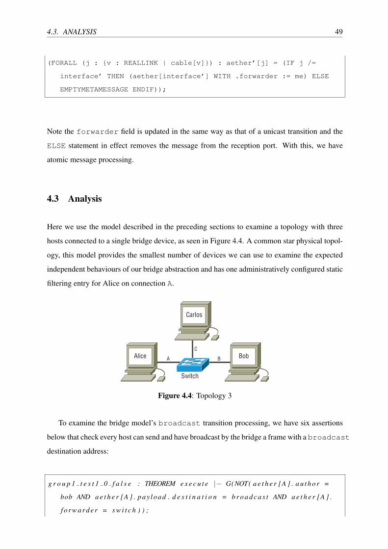
4.3. ANALYSIS 49
(FORALL (j : {v : REALLINK | cable[v]}) : aether’[j] = (IF j /=
interface’ THEN (aether[interface’] WITH .forwarder := me) ELSE
EMPTYMETAMESSAGE ENDIF));
Note the forwarder field is updated in the same way as that of a unicast transition and the
ELSE statement in effect removes the message from the reception port. With this, we have
atomic message processing.
4.3 Analysis
Here we use the model described in the preceding sections to examine a topology with three
hosts connected to a single bridge device, as seen in Figure 4.4. A common star physical topol-
ogy, this model provides the smallest number of devices we can use to examine the expected
independent behaviours of our bridge abstraction and has one administratively configured static
filtering entry for Alice on connection A.
Carlos
BobAlice A
C
B
Switch
Figure 4.4: Topology 3
To examine the bridge model’s broadcast transition processing, we have six assertions
below that check every host can send and have broadcast by the bridge a frame with a broadcast
destination address:
g r o u p 1 t e s t 1 0 f a l s e : THEOREM e x e c u t e |� G(NOT( a e t h e r [A ] . a u t h o r =
bob AND a e t h e r [A ] . pay load . d e s t i n a t i o n = b r o a d c a s t AND a e t h e r [A ] .
f o r w a r d e r = s w i t c h ) ) ;

50 CHAPTER 4. LAYER TWO - DATA-LINK
g r o u p 1 t e s t 2 0 f a l s e : THEOREM e x e c u t e |� G(NOT( a e t h e r [A ] . a u t h o r =
c a r l o s AND a e t h e r [A ] . pay load . d e s t i n a t i o n = b r o a d c a s t AND a e t h e r [A
] . f o r w a r d e r = s w i t c h ) ) ;
g r o u p 1 t e s t 3 0 f a l s e : THEOREM e x e c u t e |� G(NOT( a e t h e r [B ] . a u t h o r =
a l i c e AND a e t h e r [B ] . pay load . d e s t i n a t i o n = b r o a d c a s t AND a e t h e r [B ] .
f o r w a r d e r = s w i t c h ) ) ;
g r o u p 1 t e s t 4 0 f a l s e : THEOREM e x e c u t e |� G(NOT( a e t h e r [B ] . a u t h o r =
c a r l o s AND a e t h e r [B ] . pay load . d e s t i n a t i o n = b r o a d c a s t AND a e t h e r [B
] . f o r w a r d e r = s w i t c h ) ) ;
g r o u p 1 t e s t 5 0 f a l s e : THEOREM e x e c u t e |� G(NOT( a e t h e r [C ] . a u t h o r =
a l i c e AND a e t h e r [C ] . pay load . d e s t i n a t i o n = b r o a d c a s t AND a e t h e r [C ] .
f o r w a r d e r = s w i t c h ) ) ;
g r o u p 1 t e s t 6 0 f a l s e : THEOREM e x e c u t e |� G(NOT( a e t h e r [C ] . a u t h o r =
bob AND a e t h e r [C ] . pay load . d e s t i n a t i o n = b r o a d c a s t AND a e t h e r [C ] .
f o r w a r d e r = s w i t c h ) ) ;
Below is the counter-example generated by the group1_test1_0_false assertion above.
We can see the model start at Step 0 with the static filtering database entry for Alice, then the
transition labelled send fire, causing the state to change to Step 1 with a message generated
by Bob on network connection B, having broadcast as the destination physical address. The
bridge’s broadcast transition then fires, causing Bob’s message on network connection B to
be removed and copied to A and C with its forwarder value updated to indicate the switch
device put it there. Given group1_test1_0_false asserts network connection A can never
have a broadcast destination message forwarded by switch from Bob, the model checker
stops and provides a counter-example:
Step 0:
--- System Variables (assignments) ---
filteringdatabase[alice].acquisition = static
filteringdatabase[alice].interface = A
------------------------
Transition Information:
(module instance at [Context: topology, line(20), column(31)]

4.3. ANALYSIS 51
(module instance at [Context: topology, line(16), column(4)]
(label send
transition at [Context: host, line(74), column(8)])))
------------------------
Step 1:
--- System Variables (assignments) ---
aether[B].author = bob
aether[B].payload.destination = broadcast
aether[B].payload.source = bob
filteringdatabase[alice].acquisition = static
filteringdatabase[alice].interface = A
------------------------
Transition Information:
(module instance at [Context: topology, line(20), column(31)]
(module instance at [Context: topology, line(14), column(4)]
(label broadcast
transition at [Context: bridge, line(60), column(2)])))
------------------------
Step 2:
--- System Variables (assignments) ---
aether[A].author = bob
aether[A].forwarder = switch
aether[A].payload.destination = broadcast
aether[A].payload.source = bob
aether[C].author = bob
aether[C].forwarder = switch
aether[C].payload.destination = broadcast
aether[C].payload.source = bob
filteringdatabase[alice].acquisition = static
filteringdatabase[alice].interface = A
filteringdatabase[bob].acquisition = dynamic
filteringdatabase[bob].interface = B

52 CHAPTER 4. LAYER TWO - DATA-LINK
It must be possible for frames to be unicast between all the hosts, and we should see the filtering
database dynamically updated correctly. Below are six assertions which are designed to produce
counter-examples showing this to be the case:
g r o u p 3 t e s t 1 0 f a l s e : THEOREM e x e c u t e |� G(NOT( a e t h e r [A ] . a u t h o r =
bob AND a e t h e r [A ] . pay load . d e s t i n a t i o n = a l i c e AND
f i l t e r i n g d a t a b a s e [ a l i c e ] . i n t e r f a c e = A ) ) ;
g r o u p 3 t e s t 2 0 f a l s e : THEOREM e x e c u t e |� G(NOT( a e t h e r [A ] . a u t h o r =
c a r l o s AND a e t h e r [A ] . pay load . d e s t i n a t i o n = a l i c e AND
f i l t e r i n g d a t a b a s e [ a l i c e ] . i n t e r f a c e = A ) ) ;
g r o u p 3 t e s t 3 0 f a l s e : THEOREM e x e c u t e |� G(NOT( a e t h e r [B ] . a u t h o r =
a l i c e AND a e t h e r [B ] . pay load . d e s t i n a t i o n = bob AND
f i l t e r i n g d a t a b a s e [ bob ] . i n t e r f a c e = B ) ) ;
g r o u p 3 t e s t 4 0 f a l s e : THEOREM e x e c u t e |� G(NOT( a e t h e r [B ] . a u t h o r =
c a r l o s AND a e t h e r [B ] . pay load . d e s t i n a t i o n = bob AND
f i l t e r i n g d a t a b a s e [ bob ] . i n t e r f a c e = B ) ) ;
g r o u p 3 t e s t 5 0 f a l s e : THEOREM e x e c u t e |� G(NOT( a e t h e r [C ] . a u t h o r =
a l i c e AND a e t h e r [C ] . pay load . d e s t i n a t i o n = c a r l o s AND
f i l t e r i n g d a t a b a s e [ c a r l o s ] . i n t e r f a c e = C) ) ;
g r o u p 3 t e s t 6 0 f a l s e : THEOREM e x e c u t e |� G(NOT( a e t h e r [C ] . a u t h o r =
bob AND a e t h e r [C ] . pay load . d e s t i n a t i o n = c a r l o s AND
f i l t e r i n g d a t a b a s e [ c a r l o s ] . i n t e r f a c e = C) ) ;
Below is a counter-example provided for group3_test1_0_false, showing Bob success-
fully sending a unicast frame addressed to Alice and having the bridge forward it to Alice and
correctly updating its filtering database with a dynamic entry:
Step 0:
--- System Variables (assignments) ---
filteringdatabase[alice].acquisition = static
filteringdatabase[alice].interface = A
------------------------
Transition Information:

4.3. ANALYSIS 53
(module instance at [Context: topology, line(32), column(31)]
(module instance at [Context: topology, line(16), column(4)]
(label send
transition at [Context: host, line(74), column(8)])))
------------------------
Step 1:
--- System Variables (assignments) ---
aether[B].author = bob
aether[B].payload.destination = alice
aether[B].payload.source = bob
filteringdatabase[alice].acquisition = static
filteringdatabase[alice].interface = A
------------------------
Transition Information:
(module instance at [Context: topology, line(32), column(31)]
(module instance at [Context: topology, line(14), column(4)]
(label unicast
transition at [Context: bridge, line(41), column(2)])))
------------------------
Step 2:
--- System Variables (assignments) ---
aether[A].author = bob
aether[A].forwarder = switch
aether[A].payload.destination = alice
aether[A].payload.source = bob
filteringdatabase[alice].acquisition = static
filteringdatabase[alice].interface = A
filteringdatabase[bob].acquisition = dynamic
filteringdatabase[bob].interface = B
However, the static entry should never change and therefore messages for the static entry host
should never be forwarded to other hosts. Here are three assertions which examine this property
and find it to be true:

54 CHAPTER 4. LAYER TWO - DATA-LINK
g r o u p 4 t e s t 1 0 t r u e : THEOREM e x e c u t e |� G( f i l t e r i n g d a t a b a s e [ a l i c e ] .
a c q u i s i t i o n = b r i d g e ! s t a t i c AND f i l t e r i n g d a t a b a s e [ a l i c e ] . i n t e r f a c e
= A ) ;
g r o u p 4 t e s t 2 0 t r u e : THEOREM e x e c u t e |� G(NOT( a e t h e r [B ] . f o r w a r d e r =
s w i t c h AND a e t h e r [B ] . pay load . d e s t i n a t i o n = a l i c e ) ) ;
g r o u p 4 t e s t 3 0 t r u e : THEOREM e x e c u t e |� G(NOT( a e t h e r [C ] . f o r w a r d e r =
s w i t c h AND a e t h e r [C ] . pay load . d e s t i n a t i o n = a l i c e ) ) ;
But we expect Alice to be able to spoof her address, causing more than one MAC address to
map to her port:
g r o u p 4 t e s t 4 0 f a l s e : THEOREM e x e c u t e |� G(NOT( a e t h e r [B ] . f o r w a r d e r =
s w i t c h AND a e t h e r [B ] . pay load . s o u r c e = a l i c e AND a e t h e r [B ] . a u t h o r
/= a l i c e ) ) ;
g r o u p 4 t e s t 5 0 f a l s e : THEOREM e x e c u t e |� G(NOT( a e t h e r [C ] . f o r w a r d e r =
s w i t c h AND a e t h e r [C ] . pay load . s o u r c e = a l i c e AND a e t h e r [C ] . a u t h o r
/= a l i c e ) ) ;
In order to have confidence our abstraction faithfully represents real layer two bridge stateful
behaviour, we need to perform sanity checks upon the filtering database to ensure it is never
corrupted. Below can be seen group6_test1_0_true which ensures the bridge never has
an entry for itself in the filtering database; group6_test2_0_true and group6_test3_
0_true ensure static entries are never in the filtering database for Bob or Carlos; and group6_
test4_0_true states that for each device in the filtering database, all or none of the fields
are null.
g r o u p 6 t e s t 1 0 t r u e : THEOREM e x e c u t e |� G( f i l t e r i n g d a t a b a s e [ s w i t c h ] .
a c q u i s i t i o n = b r i d g e ! empty AND f i l t e r i n g d a t a b a s e [ s w i t c h ] . i n t e r f a c e
= NA) ;
g r o u p 6 t e s t 2 0 t r u e : THEOREM e x e c u t e |� G( f i l t e r i n g d a t a b a s e [ bob ] .
a c q u i s i t i o n /= b r i d g e ! s t a t i c ) ;

4.3. ANALYSIS 55
g r o u p 6 t e s t 3 0 t r u e : THEOREM e x e c u t e |� G( f i l t e r i n g d a t a b a s e [ c a r l o s ] .
a c q u i s i t i o n /= b r i d g e ! s t a t i c ) ;
g r o u p 6 t e s t 4 0 t r u e : THEOREM e x e c u t e |� G (FORALL ( h : HOST) :
f i l t e r i n g d a t a b a s e [ h ] . a c q u i s i t i o n = b r i d g e ! empty <=>
f i l t e r i n g d a t a b a s e [ h ] . i n t e r f a c e = NA) ;
We also need to ensure the header fields of messages are always correct after being forwarded
by asserting each network connection cannot have a message which is purportedly both from
the host connected to it and forwarded from the bridge:
g r o u p 7 t e s t 1 0 t r u e : THEOREM e x e c u t e |� G(NOT( a e t h e r [A ] . a u t h o r =
a l i c e AND a e t h e r [A ] . f o r w a r d e r = s w i t c h ) ) ;
g r o u p 7 t e s t 2 0 t r u e : THEOREM e x e c u t e |� G(NOT( a e t h e r [B ] . a u t h o r = bob
AND a e t h e r [B ] . f o r w a r d e r = s w i t c h ) ) ;
g r o u p 7 t e s t 3 0 t r u e : THEOREM e x e c u t e |� G(NOT( a e t h e r [C ] . a u t h o r =
c a r l o s AND a e t h e r [C ] . f o r w a r d e r = s w i t c h ) ) ;
The bridge should broadcast if it cannot resolve the physical address to a port:
g r o u p 2 t e s t 1 0 f a l s e : THEOREM e x e c u t e |� G(NOT( a e t h e r [B ] . f o r w a r d e r =
s w i t c h AND a e t h e r [B ] . pay load . d e s t i n a t i o n = bob AND f i l t e r
i n g d a t a b a s e [ bob ] . i n t e r f a c e = NA) ) ;
g r o u p 2 t e s t 2 0 f a l s e : THEOREM e x e c u t e |� G(NOT( a e t h e r [C ] . f o r w a r d e r =
s w i t c h AND a e t h e r [C ] . pay load . d e s t i n a t i o n = c a r l o s AND f i l
t e r i n g d a t a b a s e [ c a r l o s ] . i n t e r f a c e = NA) ) ;
Below we see the counter-example generated by the group2_test1_0_false assertion,
showing Alice send a message addressed to Bob, but the bridge broadcasting the message
to both Bob and Carlos because it does not yet have a filtering database entry indicating the
network connection on which Bob resides:

56 CHAPTER 4. LAYER TWO - DATA-LINK
Step 0:
--- System Variables (assignments) ---
filteringdatabase[alice].acquisition = static
filteringdatabase[alice].interface = A
------------------------
Transition Information:
(module instance at [Context: topology, line(28), column(31)]
(module instance at [Context: topology, line(15), column(4)]
(label send
transition at [Context: host, line(74), column(8)])))
------------------------
Step 1:
--- System Variables (assignments) ---
aether[A].author = alice
aether[A].payload.destination = bob
aether[A].payload.source = carlos
filteringdatabase[alice].acquisition = static
filteringdatabase[alice].interface = A
------------------------
Transition Information:
(module instance at [Context: topology, line(28), column(31)]
(module instance at [Context: topology, line(14), column(4)]
(label broadcast
transition at [Context: bridge, line(60), column(2)])))
------------------------
Step 2:
--- System Variables (assignments) ---
aether[B].author = alice
aether[B].forwarder = switch
aether[B].payload.destination = bob
aether[B].payload.source = carlos
aether[C].author = alice
aether[C].forwarder = switch
aether[C].payload.destination = bob

4.3. ANALYSIS 57
aether[C].payload.source = carlos
filteringdatabase[alice].acquisition = static
filteringdatabase[alice].interface = A
filteringdatabase[carlos].acquisition = dynamic
filteringdatabase[carlos].interface = A
As expected, if bad actors spoof their source address the bridge will still forward the message
(and update its filtering database entries accordingly) as seen below in the counter-example for
group8_test1_0_false.
g r o u p 8 t e s t 1 0 f a l s e : THEOREM e x e c u t e |� G(FORALL ( a : REALLINK ) :
a e t h e r [ a ] . f o r w a r d e r /= none => a e t h e r [ a ] . pay load . s o u r c e = a e t h e r [ a
] . a u t h o r ) ;
Step 0:
--- System Variables (assignments) ---
filteringdatabase[alice].acquisition = static
filteringdatabase[alice].interface = A
------------------------
Transition Information:
(module instance at [Context: topology, line(61), column(31)]
(module instance at [Context: topology, line(15), column(4)]
(label send
transition at [Context: host, line(74), column(8)])))
------------------------
Step 1:
--- System Variables (assignments) ---
aether[A].author = alice
aether[A].payload.destination = bob
aether[A].payload.source = carlos

58 CHAPTER 4. LAYER TWO - DATA-LINK
filteringdatabase[alice].acquisition = static
filteringdatabase[alice].interface = A
------------------------
Transition Information:
(module instance at [Context: topology, line(61), column(31)]
(module instance at [Context: topology, line(14), column(4)]
(label broadcast
transition at [Context: bridge, line(60), column(2)])))
------------------------
Step 2:
--- System Variables (assignments) ---
aether[B].author = alice
aether[B].forwarder = switch
aether[B].payload.destination = bob
aether[B].payload.source = carlos
aether[C].author = alice
aether[C].forwarder = switch
aether[C].payload.destination = bob
aether[C].payload.source = carlos
filteringdatabase[alice].acquisition = static
filteringdatabase[alice].interface = A
filteringdatabase[carlos].acquisition = dynamic
filteringdatabase[carlos].interface = A
4.4 Case Study One
Considering the rigour of independent component analysis undertaken in the last section to
establish the behavioural validity of our bridge abstraction, it seems reasonable to conclude
that this device will always behave as expected and therefore the standard’s specfication is
“correct”. It is true that in isolation we can have some confidence that our bridge model will
always work as expected, however this is not necessarily the case when used together with

4.4. CASE STUDY ONE 59
other components. Although likely, we can not say with any certainty the composite behaviours
our bridge will exhibit are as expected without further examination. Therefore, our research
provides the means by which such emergent properties may be analysed.
Much to our surprise, in this case study we discovered a truly unexpected behavioural
characteristic in the seemlying correct IEEE specification, which became apparent when we
examined the interaction between two of these devices. We then used the very same techniques
to prove the validity of our suggested solution to the problem.
In the same way as our previous models, we started with the simplest physical topology that
is sufficient to analyse all the behaviours of interest. In this case, we wanted to examine the
message processing behaviours and flows between two bridges. If we take our previous model
of three hosts and add another bridge, it produces Topology 4, as seen in Figure 4.5.
Carlos
BobAlice A B
C
T
SwitchA SwitchB
Figure 4.5: Topology 4
Conscious of state-space limitations, in this example we only had a single bad actor, Carlos.
The Carlos host, unlike the others, can non-deterministically choose source address of messages
he sends, thus allowing him to spoof his address, as seen in the previous section. The ability
to spoof the physical source address is unremarkable and well-known. This ability to send
spoofed messages in conjunction with a bridge’s dynamic learning behaviour means that a
malicious actor can masquerade as another host and have bi-directional “conversations” using
a fake address. Administratively set static filtering database entries seem to be a solution to
this issue. For example, an administrator might reasonably assume that if the physical address
port mapping was statically set for a router (layer three device discussed in the next chapter)
attached to a bridge, then it would not be possible for a malicious host to poison the filtering
database and masquerade as the router.

60 CHAPTER 4. LAYER TWO - DATA-LINK
The IEEE 802.1D-2004 [51] standard’s focus is on reducing broadcast traffic (for effi-
ciency). As such, it states:
“Filtering decisions are taken by the Forwarding Process on the basis of a) The
destination MAC address carried in a received frame b) The information contained
in the Filtering Database for that MAC address and reception port.”
In this way, our checks in the last section successfully proved our abstraction’s behaviour to
be faithful to this specification. The standard does not however make any mention of filtering
based on a received frame’s source address. As part of our battery of composite bridge be-
haviour checks with Topology 4, we asked SAL if Alice could have forwarded to her a message
claiming to be from Bob but actually from another host (i.e., Bob is the source address but not
the author):
g r o u p 4 t e s t 5 3 f a l s e : THEOREM e x e c u t e |� G(NOT( a e t h e r [A ] . f o r w a r d e r =
s w i t c h a AND a e t h e r [A ] . pay load . s o u r c e = bob AND a e t h e r [A ] . a u t h o r
/= bob ) ) ;
In our checks, we took it for granted the source addresses could be spoofed, however consid-
ering the bridge Carlos and Bob are attached to has a static entry for Bob on connection B, it
seemed reasonable to assume that SwitchB would discard the message, however it was not
the case, so SwitchA then forwarded the message onto Alice:
Step 0:
--- System Variables (assignments) ---
filteringdatabase.2[bob].acquisition = static
filteringdatabase.2[bob].interface = B
------------------------
Transition Information:
(module instance at [Context: topology, line(45), column(31)]
(module instance at [Context: topology, line(18), column(4)]
(label send
transition at [Context: host, line(74), column(8)])))

4.4. CASE STUDY ONE 61
------------------------
Step 1:
--- System Variables (assignments) ---
aether[C].author = carlos
aether[C].payload.destination = broadcast
aether[C].payload.source = bob
filteringdatabase.2[bob].acquisition = static
filteringdatabase.2[bob].interface = B
------------------------
Transition Information:
(module instance at [Context: topology, line(45), column(31)]
(module instance at [Context: topology, line(15), column(4)]
(label broadcast
transition at [Context: bridge, line(60), column(2)])))
------------------------
Step 2:
--- System Variables (assignments) ---
aether[B].author = carlos
aether[B].forwarder = switchb
aether[B].payload.destination = broadcast
aether[B].payload.source = bob
aether[T].author = carlos
aether[T].forwarder = switchb
aether[T].payload.destination = broadcast
aether[T].payload.source = bob
filteringdatabase.2[bob].acquisition = static
filteringdatabase.2[bob].interface = B
------------------------
Transition Information:
(module instance at [Context: topology, line(45), column(31)]
(module instance at [Context: topology, line(14), column(4)]
(label broadcast
transition at [Context: bridge, line(60), column(2)])))
------------------------
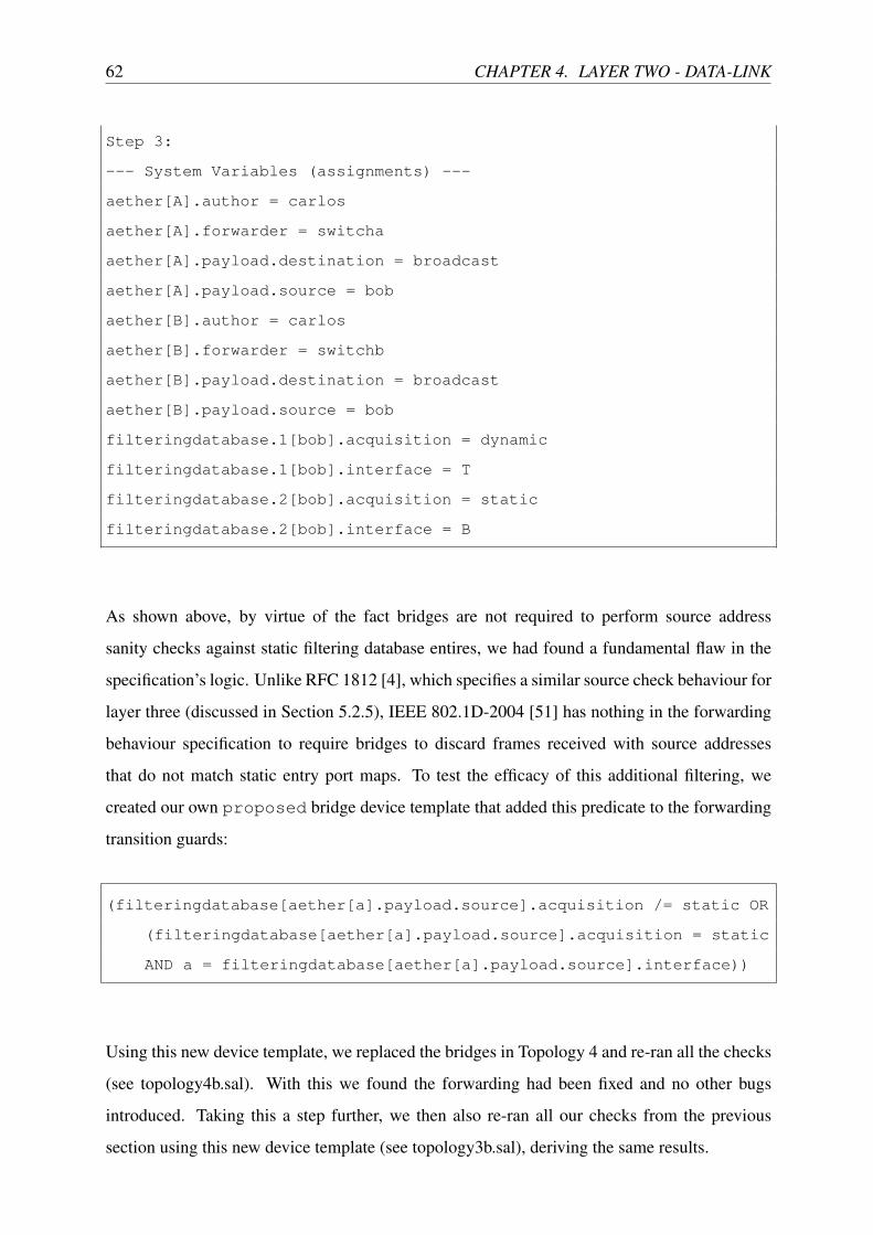
62 CHAPTER 4. LAYER TWO - DATA-LINK
Step 3:
--- System Variables (assignments) ---
aether[A].author = carlos
aether[A].forwarder = switcha
aether[A].payload.destination = broadcast
aether[A].payload.source = bob
aether[B].author = carlos
aether[B].forwarder = switchb
aether[B].payload.destination = broadcast
aether[B].payload.source = bob
filteringdatabase.1[bob].acquisition = dynamic
filteringdatabase.1[bob].interface = T
filteringdatabase.2[bob].acquisition = static
filteringdatabase.2[bob].interface = B
As shown above, by virtue of the fact bridges are not required to perform source address
sanity checks against static filtering database entires, we had found a fundamental flaw in the
specification’s logic. Unlike RFC 1812 [4], which specifies a similar source check behaviour for
layer three (discussed in Section 5.2.5), IEEE 802.1D-2004 [51] has nothing in the forwarding
behaviour specification to require bridges to discard frames received with source addresses
that do not match static entry port maps. To test the efficacy of this additional filtering, we
created our own proposed bridge device template that added this predicate to the forwarding
transition guards:
(filteringdatabase[aether[a].payload.source].acquisition /= static OR
(filteringdatabase[aether[a].payload.source].acquisition = static
AND a = filteringdatabase[aether[a].payload.source].interface))
Using this new device template, we replaced the bridges in Topology 4 and re-ran all the checks
(see topology4b.sal). With this we found the forwarding had been fixed and no other bugs
introduced. Taking this a step further, we then also re-ran all our checks from the previous
section using this new device template (see topology3b.sal), deriving the same results.
4.5. SUMMARY 63
4.5 Summary
In this chapter, we took the layer one abstraction produced in the preceding chapter and ex-
panded it to incorporate Ethernet-based (IEEE 802.3 [14] and 802.1D-2004 [51]) layer two
state and behaviours, notably the bridge device template. With the bridge device we then
showed how unlike at layer one, forwarding decisions could be made intelligently based on
addressing. Within those forwarding transitions, we also showed how the addressing used to
make those forwarding decisions can be dynamically updated, and as such introduced truly
non-deterministic device behaviour. In this chapter, with the first case study of this thesis, we
examined the composite behavioural properties of bridge devices, finding an unexpected flaw
in the IEEE 802.1D-2004 standard’s forwarding process logic, which emerged when more than
one bridge was used in a network. After determining how to resolve the flaw, we then used the
same rigorous checks to demonstrate its efficacy.

64 CHAPTER 4. LAYER TWO - DATA-LINK

Chapter 5
Layer Three - Logical Network
As with the previous layers, layer three builds upon those that come before it and provides one
key feature, logical addressing [1]. The addressing we discussed at layer two came from the
physical characteristics of the network device interfaces, and for the purposes of comparison
to logical addressing, are static. That is, the physical address of a network device’s interface is
not intended to change as it moves between networks. Logical addresses on the other hand are
determined based on the network a device connects to and are hierarchical in nature.
The hierarchical nature is crucial, as unlike physical addresses, it is this structure that makes
it possible to route traffic between networks, and ultimately to its intended recipient. Logical
addressing does not however make physical addressing redundant, rather, once a message has
found the intended destination network, physical addressing is still required to deliver the
message to the final device, indeed physical addressing is essential between each device from
origin to destination. It is this interplay between layers one, two and three that gives rise to
our modern networks, notably the Internet, and the complexities associated with large inter-
networks.
With the addition of layer three state and behaviours to our models, we are now able to
examine not just the interactions of various layers of protocols, but also the flow implications of
applied organisational policies in the form of routes and firewalls. With this chapter’s case study
we verify the work of existing literature in the analysis of intra and inter-firewall configuration
mistakes, leading to organisational policy breaches.
This chapter adds to our model template library the router device, based upon the most
authoritative specification we could acquire, RFC 1812 [4]. The router sits between networks,
65

66 CHAPTER 5. LAYER THREE - LOGICAL NETWORK
and based upon layer three addressing, routes and filters traffic between networks. Vastly more
complex that the bridge of layer two, the router has additional state and uses multiple protocols
during the translation of physical addresses as it makes inter-network routing decisions.
5.1 State Abstraction
In this section we have a subsection for each aspect of this layer’s state.
5.1.1 Logical Addressing
As seen in Figure 5.1, the Internet Protocol version 4 (IPv4) header from RFC 791 [25] is
considerably more complex than its layer two Ethernet counterpart. In some respects, this
additional complexity is due to extensibility, such as “options” (examined at length in the next
chapter) and also the degree of dependency layer four transport layer protocols in the same suite
have with IPv4 at layer three. In this way, the TCP/IPv4 suite breaks with the OSI model’s goal
of inter-operability, however given its ubiquity it is the protocol used here for our abstraction.
VER DS
Protocol
Source IP address
Destination IP address
Option
Time to live
Flags
Total length
Header checksum
Fragmentation offset
HLEN
Identification
Figure 5.1: IPv4 Datagram PDU
In the same way as layer two, we remove all liveness and size-related fields in our abstrac-
tion, including: HLEN, DS, total length, and header checksum. The version field is always 4
(because IPv6 is not within the scope of our research), and thus can simply be removed, however

5.1. STATE ABSTRACTION 67
the remaining fields require further consideration.
IPv4 datagrams whose size is greater than the maximum transmission unit (MTU) of the
underlying layers are broken into permissible size chunks called “fragments” for transmission,
which are then reassembled by the recipient using the identification, offset and flags fields. The
identification field groups fragments together. The offset indicates the order in which fragments
should be reassembled, and the “more fragments” flag is set in all fragments until the last,
signalling the completion of fragment transmission.
Our messages do not require any form of fragmentation, as they are always fixed length by
virtue of their finite state. However, we did consider the merit of modelling the fragmentation,
transmission and reassembly process, but it was deemed to be of little to no experimental benefit.
As a result, all fragmentation related fields were removed from our abstraction.
The Time To Live (TTL) field is a discrete positive integer (non-negative whole number)
that is decremented by each router that processes a datagram. Should the TTL value be zero
after being decremented, the message is discarded and an error sent to the sender. This process
is performed principally to prevent messages being stuck in routing loops. Given our primary
goal here is to derive a means which all flows can be examined (arguably this could include
routing loops), we decided a TTL field to be unnecessary in our message abstraction.
The protocol field indicates the protocol used in the payload’s layer four contents. Our thesis
does not include layer four and thus has no need for this field. We did experiment with this and
a similar albeit more abstract field to indicate application layer protocol use for the purposes of
modelling more advanced filtering techniques; however this remains a possible area of future
work.
Finally we come to the three fields included in our abstraction: source IP address, destination
IP address and options. An IPv4 address is a 32bit integer, commonly written as a series of
bytes (8 bits and therefore a possible range of values 0–255) groups, separated by full-stops, for
example, 131.181.26.200. This address space provides more than four billion unique addresses.
Naturally we cannot possibly include such a large data structure in a finite-state model, so
we re-used the enumerated list of devices from layer one again (as was done with layer two).
This then posed a problem because logical addresses use masks as as the basis of network
address delineation and thus routing. To overcome this limitation we in effect applied the mask
then enumerated the list of networks in the same way as was done for the hosts and gave the

68 CHAPTER 5. LAYER THREE - LOGICAL NETWORK
network portion of an address its own protocol header fields in tandem with both the source and
destination addresses, as seen in Figure 5.2 at the Network layer.
Layer Three - Network
Layer Two - Data-link
Layer One - Physical
Source host address andsource network address
Source address
Author address
Destination host address anddestination network address
Destination address
Forwarder address
Category set label
Figure 5.2: Message abstraction
There was still one difficulty with this approach, and that was due to the fact an enumerated
list could not be subnetted; in fact the host portion of a real logical address is entirely determined
by the mask applied, which may change as a message is routed and therefore the interpretation
of the network the message comes from and is destined for. As a result, we could only represent
one depth of hierarchy. Arguably not a significant issue, as the networks capable of being
represented in a finite-state model must be representative in size anyway, however we did
produce a viable work around.
Routers commonly perform what is known as route summation [54], that is, if more than
one network has a common parent subnet (also known as a supernet), and next hop address, the
routes are often consolidated into a single route for efficiency using the supernet mask. This can
greatly reduce the size of routing tables (discussed further in Section 5.1.2), without impacting
upon functional correctness. Without abstraction, should it be necessary to represent subnets
of greater than one depth, we merely enumerate rather than summarise the routes, and faithful
routing behaviour is demonstrated.
As with Ethernet at layer two, IPv4 at layer three has three types of addresses: unicast,
multicast and broadcast. Just as with layer two, we do not include multicast at layer three
due to the significant additional complexity and state which does not add significant value.
Conceivably, multicast communication could be represented as just another address in the
enumerated data structure, with multiple hosts choosing to use both their unicast, multicast
and broadcast address for communication, however just like multicast at layer two, unless our
goal is to examine multicast protocols (which ours is not), their flow characteristics are in the

5.1. STATE ABSTRACTION 69
main an efficiency of broadcast, and therefore not arguably safety property related. Multicast
group membership is opt-in and as Section 2.2.6 of RFC 1812 [4] states: “The sender of the
datagram does not itself need to be a member of the destination group”.
5.1.2 Route Table
The role of the layer three route table is akin to that of the layer two bridge’s filtering database in
the sense that it’s used as a lookup. Incidently, the router also has a filtering database, however
this is known as an ARP table, and is discussed later in this chapter. The routing table is used
for making routing decisions about how to process messages by looking up received messages’
destination network in the routing table, and resolving them to an outgoing interface.
Routes come in three varieties in terms of how they are processed: local, next-hop and
default. Local routes are those of the networks the router is directly attached to. Next-hop routes
are for networks which are not directly attached and indicate where messages for a network
should be routed to. Finally, a default route is the catch-all route that indicates where messages
should be routed to if no route is known for the destination network.
Table 5.1: Local Route Table
Logical Network Interfaceleft Aatoc ACbtoa BA
In our abstraction, due to the difficulties of representing and predicating a finite-state data
structure to accommodate these three permutations, we separated them out into their own
structures. The structure of the locally attached network table can be seen in Table 5.1 and
is represented in SAL like so:
attached : ARRAY LOGICALNETWORK OF topology!LINK
As can be seen, it’s a simple mapping of local networks to interfaces. The next-hop table on the
other hand can be seen in Table 5.2, and shows which device (i.e., router) on to which non-local

70 CHAPTER 5. LAYER THREE - LOGICAL NETWORK
network messages should be forwarded to and is represented in SAL like so:
routes : ARRAY LOGICALNETWORK OF ARRAY LOGICALNETWORK OF topology!
NODE
Table 5.2: Next-hop Route Table
Logical Network Via Hostright atoc RouterCright btoa RouterB
The last data structure is the default route (of which there can only be a maximum of one),
and is essentially one next-hop entry:
defaultroute : [# lognet : topology!LOGICALNETWORKADDR, loghost :
topology!NODE #]
Table 5.3: Default Route Table
Via Hostatoc RouterC
Next-hop route entries can be statically prescribed by the administrator or learnt using
dynamic routing protocols. However the routing tables are for our purposes here the same
irrespective of the method used to generate their entries. In this way, dynamic routing protocols
are outside the scope of this thesis.
5.1.3 ACLs
Access Control Lists (ACLs) in the context of layer three filtering are known more simply as
firewall rules. These rules are always an ordered set, and as such we can represent them in SAL

5.1. STATE ABSTRACTION 71
like so:
firewall_rules : ARRAY topology!FIREWALLSIZE OF ACL
The FIREWALLSIZE integer index to this array is important for two reasons. Firstly, it pro-
vides a simple bounded index, but secondly and most importantly, it orders them in such a way
as to facilitate predicated processing, faithfully mimicking the behaviour of real firewalls – this
is discussed at greater length in Section 5.2.6. The second notable feature of this representation
is the use of the ACL data structure for firewall rules, which we define in SAL like so:
ACL : TYPE = [# SRC_host : topology!NODE, SRC_net : topology!
LOGICALNETWORKADDR, DST_host : topology!NODE, DST_net : topology!
LOGICALNETWORKADDR, action : ACTION #];
Given FIREWALLSIZE must be a global constant, it must be the size of the biggest firewall in
the topology; a firewall being administratively set at the time of router instantiation need only
use an ELSE statement to fill any remaining unused entries:
[[r : FIREWALLSIZE] IF r = 1 THEN (# SRC_host := none, SRC_net :=
null, DST_host := none, DST_net := atoc, action := DISCARD #)
ELSIF r = 2 THEN (# SRC_host := none, SRC_net := null, DST_host :=
none, DST_net := btoa, action := DISCARD #) ELSIF r = 3 THEN (#
SRC_host := Alice, SRC_net := left, DST_host := none, DST_net :=
null, action := ACCEPT #) ELSIF r = 4 THEN (# SRC_host := none,
SRC_net := left, DST_host := none, DST_net := null, action :=
DISCARD #) ELSE (# SRC_host := none, SRC_net := null, DST_host :=
none, DST_net := null, action := ACCEPT #) ENDIF]
The firewall above when represented as a table can been seen in Table 5.4.

72 CHAPTER 5. LAYER THREE - LOGICAL NETWORK
Rule Source Host Source Network Destination Host Destination Network Action1 * * * atoc DISCARD2 * * * btoa DISCARD3 Alice left * * ACCEPT4 * left * * DISCARD5 * * * * ACCEPT
Table 5.4: Firewall Rule Table
It should be noted that in just the same way that layer three headers have the network and
host portions of addresses as separate fields (discussed in Section 5.1.1), so to do we have them
separate in the ACL data structure.
5.2 Behaviour Abstraction
Conceptually, a router’s behaviour is quite similar to that of a layer two bridge. It’s a device
with more than one network interface, which intelligently forwards traffic between them based
on addressing. However, unlike a bridge, a router has to transform the layer two addressing
properties of messages as it forwards them. In order to do this, the router must use supplemen-
tary protocols to discover layer two addresses. Furthermore, choosing the destination interface
is not merely a choice between unicast and broadcast; a router must decide the type of unicast to
be performed (local, next-hop or default route), in conjunction with filtering. As RFC 1812 [4]
states, “Routing is a complex and difficult problem”. This section details how we have produced
an abstraction of these dynamic interactive behaviours.
5.2.1 ARP
Address Resolution Protocol (ARP) is part of the TCP/IPv4 suite of protocols and has arguably
the most complex of all the behaviours we model in this thesis, as it is dynamic but predicated
by other protocols. ARP operates at layer three (not as a payload of IPv4) and is used to discover
the layer two physical address for a given layer three address. In other words, if a device wishes
to send to a logical address on the same network, but does not know its corresponding physical
address, ARP is used.
ARP functions by sending a message to the logical address with the physical address being

5.2. BEHAVIOUR ABSTRACTION 73
broadcast, so that every device on the network can see the request. Should a device on that
network have that logical address, it is expected to respond. Due to the fact the response
will have both the physical and logical source addresses of the desired device, the requester
then knows the logical address’ corresponding physical address, and can unicast, rather than
broadcast all subsequent traffic to that device.
Although used by all devices implementing the TCP/IP suite, ARP was not included in our
host templates, as they non-deterministically choose the addressing of messages they send and
therefore do not need another set of transitions for handling ARP. This approach also means we
can better analyse the behaviours resulting from messages being produced, including those with
malicious intent. However, unlike our host template, our router did need to use ARP to resolve
logical addresses as part of the routing process and so transitions were required to send and
receive ARP messages. Due to the fact ARP uses effectively the same fields that are already in
our message abstraction (source and destination addresses), we did not need to add additional
state to our models to faithfully represent ARP messages.
The reception of ARP responses was relatively simple, as it could be encompassed by a gen-
eral local delivery transition whose job it was to receive any valid messages addressed
to the router, and as part of that transition it would update the ARP table in just the same way
as a real device.
The challenge came when we needed to trigger the sending of ARP requests in response to
routing that was being blocked due to an unknown destination physical address or responding to
other devices’ ARP requests. We found that due to the non-deterministic sending of messages
by hosts, we did not require a transition for resolving hosts on the local network, but routers
do not non-deterministically produce messages and so separate ARP send transitions were
required for next-hop and default routing. They look similar in nature to other forwarding-
type transitions in that they non-deterministically choose an incoming message on an interface,
but rather than cause that message to be transformed and forwarded, they cause the router to
produce an ARP request on the destination interface of the message (if a resolution does not
already exist in the ARP table):
(FORALL (c : LOGICALNETWORK) :

74 CHAPTER 5. LAYER THREE - LOGICAL NETWORK
routes[aether[a].payload.payload.destinationnetwork][c] /=
topology!none =>
resolv[routes[aether[a].payload.payload.
destinationnetwork][c]].interface /= attached[c]
AND aether[attached[c]].payload.payload.sourcehost
/= routes[aether[a].payload.payload.
destinationnetwork][c])
This predicate is from the next-hop ARP send transition and requires a next-hop route to exist
for the message being processed but not a local route. In contrast, the default route ARP
send transition is predicated by the following condition which says the default route cannot
be resolved, the destination network is not directly attached to this router and a next-hop route
does not exist for the destination network:
attached[defaultroute.lognet] /= resolv[defaultroute.loghost].
interface AND
attached[aether[a].payload.payload.destinationnetwork] = topology!NA
AND
(FORALL (b : LOGICALNETWORK) :
routes[aether[a].payload.payload.destinationnetwork][b] =
topology!none)
However, the ARP send transitions also differ in that a next-hop network must be non-deter-
ministically chosen (as a fundamental principle of routing is that multiple paths can and often
do exist to a destination network). Below shows the selection of a next-hop network requir-
ing resolution using ARP. The predicate requires a route to the previously selected message’s
destination network to exist via the next-hop network and that next-hop to not yet have been
resolved:
nexthopnetwork’ IN {b : LOGICALNETWORK |

5.2. BEHAVIOUR ABSTRACTION 75
routes[aether[interface’].payload.payload.destinationnetwork
][b] /= topology!none AND
(resolv[routes[aether[interface’].payload.payload.
destinationnetwork][b]].phyaddr = topology!none OR (resolv
[routes[aether[interface’].payload.payload.
destinationnetwork][b]].phyaddr /= topology!none AND
resolv[routes[aether[interface’].payload.payload.
destinationnetwork][b]].interface /= attached[b])) AND
aether[attached[b]].payload.source /= me AND
aether[attached[b]].payload.destination /= topology!broadcast
AND
aether[attached[b]].payload.payload.destinationhost /= routes
[aether[interface’].payload.payload.destinationnetwork][b]
AND
aether[attached[b]].payload.payload.destinationnetwork /= b
AND
aether[attached[b]].payload.payload.sourcehost /= me AND
aether[attached[b]].payload.payload.sourcenetwork /= b};
Both ARP send transitions must also use their respective lookups to correctly populate the fields
of the ARP message they are producing, notably, the network fields (N.B. this is not trivial
considering routers by their very nature are attached to multiple networks), and the destination
router’s logical host address:
aether’ = aether WITH [attached[nexthopnetwork’]] := (((((((
EMPTYMETAMESSAGE WITH .author := me) WITH .payload.
source := me) WITH .payload.destination := topology!broadcast) WITH .
payload.payload.sourcenetwork := nexthopnetwork’) WITH .payload.
payload.sourcehost := me) WITH .payload.payload.destinationnetwork
:= nexthopnetwork’) WITH .payload.payload.destinationhost :=
routes[aether[interface’].payload.payload.destinationnetwork][
nexthopnetwork’])

76 CHAPTER 5. LAYER THREE - LOGICAL NETWORK
Finally, routers need another transition by which they can respond to these ARP requests. We
have created a function called arprequest?, which is used by the ARP response transition
and simply identifies the properties of a valid ARP request:
arprequest?(me : HOST, msg : METAMESSAGE, interface : REALLINK,
attached : ARRAY LOGICALNETWORK OF topology!LINK) : BOOLEAN =
msg.payload.source /= me AND
msg.payload.source /= topology!broadcast AND
msg.payload.destination = topology!broadcast AND
msg.payload.payload.destinationhost = me AND
attached[msg.payload.payload.destinationnetwork] = interface
AND
msg.payload.payload.sourcehost /= me AND
msg.payload.payload.sourcenetwork = msg.payload.payload.
destinationnetwork;
In the body of the transition, an ARP response is unicast back to the requester like so:
aether’ = aether WITH [interface’] := (((((((EMPTYMETAMESSAGE WITH .
author := me) WITH .payload.source := me) W
ITH .payload.destination := aether[interface’].payload.source) WITH .
payload.payload.sourcenetwork := aether[interface’].payloa
d.payload.sourcenetwork) WITH .payload.payload.sourcehost := me) WITH
.payload.payload.destinationnetwork := aether[interface’]
.payload.payload.destinationnetwork) WITH .payload.payload.
destinationhost := aether[interface’].payload.payload.sourcehost)

5.2. BEHAVIOUR ABSTRACTION 77
5.2.2 Local Route
Local routing is perhaps the simplest of the three routing behaviours. The router has a table
mapping directly attached logical networks to its interfaces (as discussed in Section 5.1.2),
which is used to predicate the non-deterministic selection of a received message waiting to be
processed:
attached[aether[a].payload.payload.destinationnetwork] /= topology!NA
It is also guarded by the contents of the ARP table, to ensure that any attempt to route the
message will successfully translate the layer two physical destination address and that the
route/ARP destination interfaces match:
resolv[aether[a].payload.payload.destinationhost].phyaddr /= topology
!none AND
resolv[aether[a].payload.payload.destinationhost].interface =
attached[aether[a].payload.payload.destinationnetwork]
Should these conditions hold, the message is transformed and routed to the local destination
network:
aether’ = (aether WITH [attached[aether[interface’].payload.payload.
destinationnetwork]] := ((((aether[interface’] WITH .forwarder :=
me) WITH .payload.source := me) WITH .payload.destination :=
resolv[aether[interface’].payload.payload.destinationhost].phyaddr
))) WITH [interface’] := EMPTYMETAMESSAGE

78 CHAPTER 5. LAYER THREE - LOGICAL NETWORK
5.2.3 Next Hop Route
Next-hop routing is somewhat more complex than that of local routing, as there may be more
than one valid next-hop route for any given destination network. As with many other aspects of
our models, we used the model checker’s ablity to non-deterministically evaluate these choices.
First, in the received message choice, we must add a predicate to ensure a next-hop route exists
for the destination network:
(EXISTS (b : LOGICALNETWORK) : resolv[routes[aether[a].payload.
payload.destinationnetwork][b]].phyaddr /= topology!none)
Should that be true, we must then make another non-deterministic choice, this time for the route
the message will take:
nexthopnetwork’ IN {b : LOGICALNETWORK |
resolv[routes[aether[interface’].payload.payload.
destinationnetwork][b]].phyaddr /= topology!none AND
resolv[routes[aether[interface’].payload.payload.
destinationnetwork][b]].interface = attached[b]};
It is important to note here that real router implemenations associate a “cost” with each route,
and will typically choose the lowest cost route, however we deliberately do not incorporate
cost into our modelling here, as our interest is exclusively with reachability safety properties,
principally, can message A get to place B and in what way will it change as it is propagated.
5.2.4 Default Route
The default route (should it exist), is the third type of route and is used only if no other route is
known for the destination network of a message. Without a default route, any message received,
for which a route is unknown, must be discarded. First and foremost, we guard the default route
transition with the requirement of a default route existing:

5.2. BEHAVIOUR ABSTRACTION 79
defaultroute.lognet /= topology!null
A requirement in the message selection guard ensures no “better” local or next-hop route exists
for the destination network:
attached[aether[a].payload.payload.destinationnetwork] = topology!NA
AND
(FORALL (b : LOGICALNETWORK) :
routes[aether[a].payload.payload.destinationnetwork][b] =
topology!none)
Finally, the ARP table must be able to resolve the default route’s logical to a physical address:
resolv[defaultroute.loghost].interface = attached[defaultroute.lognet
]
5.2.5 Source Network Check
Section 5.3.8 of RFC 1812 [4] states that a router should be capable of checking the claimed
source network of a message prior to routing it to another network. For example, if a message
being received on an interface says it is from network C but the routing table says that a route to
that network is only present on other interfaces, it is erroneous and likely an attempt at spoofing.
For this reason, a router may discard such a message if administratively configured to do so. As
such, we have implemented this logic into a function called sourcenetworkvalid. This
function predicates all non-deterministic message selection guards, just as with the message
waiting? function. Furthermore, when used, the sourcenetworkvalid function is ORed
by a donotchecksource variable mimicking an administratively set configuration to turn

80 CHAPTER 5. LAYER THREE - LOGICAL NETWORK
this feature on and off for a given router:
(sourcenetworkvalid(a, attached, routes, defaultroute, aether) OR
donotchecksource)
Below is the function definition for sourcenetworkvalid:
sourcenetworkvalid(receptioninterface : REALLINK, attached : ARRAY
LOGICALNETWORK OF topology!LINK, routes : ARRAY LOGICALNETWORK OF
ARRAY LOGICALNETWORK OF topology!NODE, defaultroute : [# lognet :
topology!LOGICALNETWORKADDR, loghost : topology!NODE #], aether :
NETWORK) : BOOLEAN =
As seen above, the function takes all the state required to make a decision as arguments, includ-
ing the message interface, routes and the network itself. Using these parameters, sourcenet
workvalid asserts that the interface the message was received on is local and maps to that
interface:
receptioninterface = attached[aether[receptioninterface].payload.
payload.sourcenetwork] OR
Alternatively, a next-hop route exists for this message’s source network, which maps to the
interface it was received on:
(EXISTS (c : LOGICALNETWORK) : routes[aether[receptioninterface].
payload.payload.sourcenetwork][c] /= topology!none AND
receptioninterface = attached[c]) OR
Another alternative is that the message was received on the default route interface and a local

5.2. BEHAVIOUR ABSTRACTION 81
or next-hop network route does not exist for it:
(receptioninterface = attached[defaultroute.lognet] AND attached[
aether[receptioninterface].payload.payload.sourcenetwork] =
topology!NA AND NOT (EXISTS (c : LOGICALNETWORK) : routes[aether[
receptioninterface].payload.payload.sourcenetwork][c] /= topology!
none AND receptioninterface = attached[c]))
5.2.6 Filtering
Filtering of layer three traffic (also known as firewalling), stands next to the ARP protocol as
one of the most challenging behaviours to faithfully represent in our finite-state abstraction.
From a procedural programming point of view, these behaviours are simple, however they do
not easily translate into predicate guarded transitions.
The filtering behaviour, at its most fundamental, evaluates each successive ACL rule in the
ordered set and the first to match the layer three addressing of the message under consideration
is processed according to the action of that rule (accept/discard). To replicate this behaviour, we
need to express this sequential process as a set operation. At the highest level of abstraction, it
is simply: does a matching accept rule exist before a matching discard rule? We translated this
into a SAL function called permittraffic?, which then predicates all of the router’s layer
three processing transitions (routing behaviours):
permittraffic?(firewall_rules : ARRAY topology!FIREWALLSIZE OF ACL,
msg : METAMESSAGE) : BOOLEAN =
EXISTS (r : topology!FIREWALLSIZE) : (firewall_rules[r].
action = ACCEPT AND
( (firewall_rules[r].SRC_host = topology!none AND

82 CHAPTER 5. LAYER THREE - LOGICAL NETWORK
(firewall_rules[r].SRC_net = msg.payload.
payload.sourcenetwork OR firewall_rules[r
].SRC_net = topology!
null))
OR
(firewall_rules[r].SRC_host = msg.payload.payload.
sourcehost AND firewall_rules[r].SRC_net = msg.
payload.payl
oad.sourcenetwork)
)
AND
( (firewall_rules[r].DST_host = topology!none AND
(firewall_rules[r].DST_net = msg.payload.
payload.destinationnetwork OR
firewall_rules[r].DST_net = topology!null)
)
OR
(firewall_rules[r].DST_host = msg.payload.payload.
destinationhost AND firewall_rules[r].DST_net =
msg.payload.payload.destinationnetwork)
)
AND NOT (EXISTS (f : topology!FIREWALLSIZE) : (
firewall_rules[f].action = DISCARD AND
( (firewall_rules[f].SRC_host = topology!none
AND
(firewall_rules[f].SRC_net = msg.
payload.payload.sourcenetwork OR
firewall_rules[f].SRC_net =
topology!null))
OR

5.2. BEHAVIOUR ABSTRACTION 83
(firewall_rules[f].SRC_host = msg.payload.
payload.sourcehost AND firewall_rules[f].
SRC_net = msg.payload.payload.
sourcenetwork)
)
AND
( (firewall_rules[f].DST_host = topology!none
AND
(firewall_rules[f].DST_net = msg.
payload.payload.destinationnetwork
OR firewall_rules[f].DST_net =
topology!null))
OR
(firewall_rules[f].DST_host = msg.payload.
payload.destinationhost AND firewall_rules
[f].DST_net = msg.payload.payload.
destinationnetwork)
)
AND f < r)));
Within each of the EXISTS operations seen above are two groups of predicates, one for the
source address and one for the destination address. Within those are checks to match if a host
field value is unspecified (i.e., a wild card to match any host), or the host being considered, in
conjunction with a network comparison. In the second EXISTS operation, a check is performed
using the rule index to ensure that any matching discard rule does not come before an accept
rule in the rule set.
The reader may notice that layer four protocol and transport port numbers are not included.
Neither our network abstraction, nor RFC 1812 [4] include layer four. Although extending
the same logic as seen above to layer four should not be especially onerous, it would however
greatly increase the already very large state-space and falls outside the scope of our work here.
It therefore follows that our filtering is not stateful.
It should be noted that firewalls normally have a default rule, which indicates the action to

84 CHAPTER 5. LAYER THREE - LOGICAL NETWORK
be taken, should no other rule match. In our abstraction this capacity is provided by simply
making the last rule in the set a wildcard entry with the associated action:
(# SRC_host := none, SRC_net := null, DST_host := none, DST_net :=
null, action := DISCARD #)
5.3 Analysis
In the same fashion as our previous analysis sections, we have produced a topology that has
the minimum number of representative devices to facilitate the examination of all our router’s
expected behaviours. However, unlike the solitary bridge model used in last chapter’s analysis
section, this three router model is also capable of providing the means to examine emergent
composite behavioural properties.
B
Carlos
Top Network
Bob
Right Network
Alice
Left Network
RouterA RouterB
RouterC
A
C
ctobBCAC
AB
atoc
btoa
RouterA
HostNetwork via
Left
Left
Right
Right
Default
atoc
ctob
atoc
ctob
none none
RouterB
RouterA
RouterB
RouterC
HostNetwork via
Right
Right
Default
atoc
btoa
atoc
RouterB
RouterC
RouterC
HostNetwork via
Left
Left
Default
ctob
btoa
btoa
RouterA
RouterA
Figure 5.3: Topology 5
The topology configuration seen in Figure 5.3 was designed to provide the means by which

5.3. ANALYSIS 85
the safety properties of routing composite behaviours can be exhaustively examined. In this
way, we have produced the following goals from which this section’s proofs are based to ensure
they exhaustively examine those behaviours:
1. Prove the configuration (such as routes) are correctly encoded into the device instantiation
parameters
2. Test every route (including those to inter-router networks)
3. Test every type of route in conjunction with every other type of route
4. Show that next-hop routes are non-deterministically chosen
5. Show redundant routes
6. Show impossible routes (due to isolated and composite behaviours)
7. Prove the source network check works correctly
8. Demonstrate what can occur with the source network check enabled and disabled
9. Perform ARP sanity checks
10. Show how filtering can be used to apply AS1 policies (more extensive filtering analysis is
performed in Section 5.4)
The routing tables seen in Figure 5.3 have been designed to demonstrate that although two
physical paths exist between any two given hosts, the traffic cannot necessarily be routed via all
paths. We expect Alice, Bob and Carlos to be able to send and receive one another’s messages
via at least one route, so to check this we assert that this is not the case to produce a counter-
example:
g r o u p 1 t e s t 1 8 f a l s e : THEOREM e x e c u t e |� G( a e t h e r [B ] . a u t h o r /= A l i c e
) ;
g r o u p 1 t e s t 4 8 f a l s e : THEOREM e x e c u t e |� G( a e t h e r [C ] . a u t h o r /= A l i c e
) ;
g r o u p 2 t e s t 1 8 f a l s e : THEOREM e x e c u t e |� G( a e t h e r [A ] . a u t h o r /= Bob ) ;
1Autonomous System (AS) is a network under the administration of a single entity – for example, an InternetService Provider.
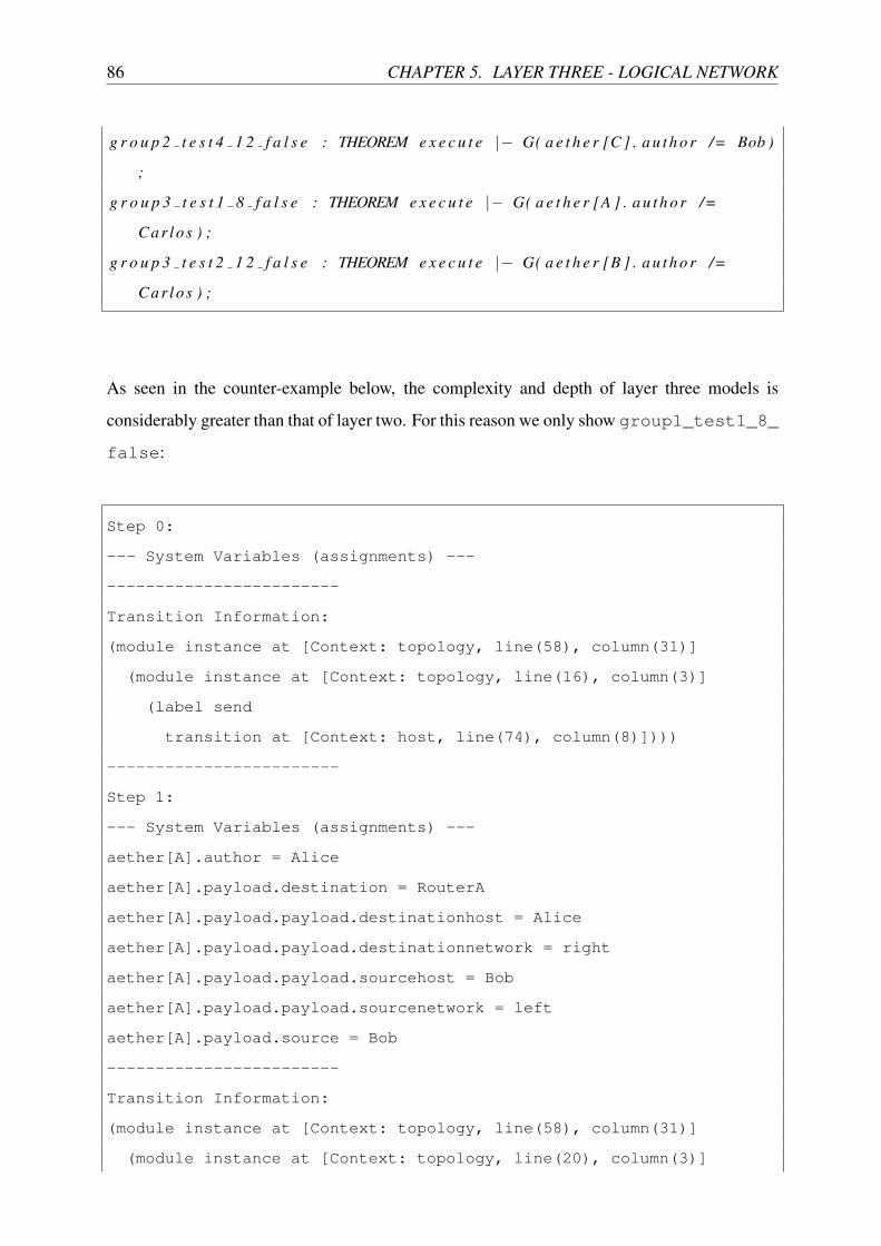
86 CHAPTER 5. LAYER THREE - LOGICAL NETWORK
g r o u p 2 t e s t 4 1 2 f a l s e : THEOREM e x e c u t e |� G( a e t h e r [C ] . a u t h o r /= Bob )
;
g r o u p 3 t e s t 1 8 f a l s e : THEOREM e x e c u t e |� G( a e t h e r [A ] . a u t h o r /=
Ca r lo s ) ;
g r o u p 3 t e s t 2 1 2 f a l s e : THEOREM e x e c u t e |� G( a e t h e r [B ] . a u t h o r /=
Ca r lo s ) ;
As seen in the counter-example below, the complexity and depth of layer three models is
considerably greater than that of layer two. For this reason we only show group1_test1_8_
false:
Step 0:
--- System Variables (assignments) ---
------------------------
Transition Information:
(module instance at [Context: topology, line(58), column(31)]
(module instance at [Context: topology, line(16), column(3)]
(label send
transition at [Context: host, line(74), column(8)])))
------------------------
Step 1:
--- System Variables (assignments) ---
aether[A].author = Alice
aether[A].payload.destination = RouterA
aether[A].payload.payload.destinationhost = Alice
aether[A].payload.payload.destinationnetwork = right
aether[A].payload.payload.sourcehost = Bob
aether[A].payload.payload.sourcenetwork = left
aether[A].payload.source = Bob
------------------------
Transition Information:
(module instance at [Context: topology, line(58), column(31)]
(module instance at [Context: topology, line(20), column(3)]

5.3. ANALYSIS 87
(label sendARPtoresolvenexthop
transition at [Context: router, line(100), column(2)])))
------------------------
Step 2:
--- System Variables (assignments) ---
aether[A].author = Alice
aether[A].payload.destination = RouterA
aether[A].payload.payload.destinationhost = Alice
aether[A].payload.payload.destinationnetwork = right
aether[A].payload.payload.sourcehost = Bob
aether[A].payload.payload.sourcenetwork = left
aether[A].payload.source = Bob
aether[BA].author = RouterA
aether[BA].payload.destination = broadcast
aether[BA].payload.payload.destinationhost = RouterB
aether[BA].payload.payload.destinationnetwork = btoa
aether[BA].payload.payload.sourcehost = RouterA
aether[BA].payload.payload.sourcenetwork = btoa
aether[BA].payload.source = RouterA
------------------------
Transition Information:
(module instance at [Context: topology, line(58), column(31)]
(module instance at [Context: topology, line(18), column(3)]
(label send
transition at [Context: host, line(74), column(8)])))
------------------------
Step 3:
--- System Variables (assignments) ---
aether[A].author = Alice
aether[A].payload.destination = RouterA
aether[A].payload.payload.destinationhost = Alice
aether[A].payload.payload.destinationnetwork = right
aether[A].payload.payload.sourcehost = Bob
aether[A].payload.payload.sourcenetwork = left

88 CHAPTER 5. LAYER THREE - LOGICAL NETWORK
aether[A].payload.source = Bob
aether[B].author = Bob
aether[B].payload.destination = RouterB
aether[B].payload.payload.destinationhost = RouterB
aether[B].payload.payload.destinationnetwork = right
aether[B].payload.payload.sourcehost = Alice
aether[B].payload.payload.sourcenetwork = right
aether[B].payload.source = Alice
aether[BA].author = RouterA
aether[BA].payload.destination = broadcast
aether[BA].payload.payload.destinationhost = RouterB
aether[BA].payload.payload.destinationnetwork = btoa
aether[BA].payload.payload.sourcehost = RouterA
aether[BA].payload.payload.sourcenetwork = btoa
aether[BA].payload.source = RouterA
------------------------
Transition Information:
(module instance at [Context: topology, line(58), column(31)]
(module instance at [Context: topology, line(42), column(3)]
(label sendARPresponse
transition at [Context: router, line(82), column(2)])))
------------------------
Step 4:
--- System Variables (assignments) ---
aether[A].author = Alice
aether[A].payload.destination = RouterA
aether[A].payload.payload.destinationhost = Alice
aether[A].payload.payload.destinationnetwork = right
aether[A].payload.payload.sourcehost = Bob
aether[A].payload.payload.sourcenetwork = left
aether[A].payload.source = Bob
aether[B].author = Bob
aether[B].payload.destination = RouterB
aether[B].payload.payload.destinationhost = RouterB

5.3. ANALYSIS 89
aether[B].payload.payload.destinationnetwork = right
aether[B].payload.payload.sourcehost = Alice
aether[B].payload.payload.sourcenetwork = right
aether[B].payload.source = Alice
aether[BA].author = RouterB
aether[BA].payload.destination = RouterA
aether[BA].payload.payload.destinationhost = RouterA
aether[BA].payload.payload.destinationnetwork = btoa
aether[BA].payload.payload.sourcehost = RouterB
aether[BA].payload.payload.sourcenetwork = btoa
aether[BA].payload.source = RouterB
resolv.2[RouterA].interface = BA
resolv.2[RouterA].phyaddr = RouterA
------------------------
Transition Information:
(module instance at [Context: topology, line(58), column(31)]
(module instance at [Context: topology, line(20), column(3)]
(label localdelivery
transition at [Context: router, line(160), column(2)])))
------------------------
Step 5:
--- System Variables (assignments) ---
aether[A].author = Alice
aether[A].payload.destination = RouterA
aether[A].payload.payload.destinationhost = Alice
aether[A].payload.payload.destinationnetwork = right
aether[A].payload.payload.sourcehost = Bob
aether[A].payload.payload.sourcenetwork = left
aether[A].payload.source = Bob
aether[B].author = Bob
aether[B].payload.destination = RouterB
aether[B].payload.payload.destinationhost = RouterB
aether[B].payload.payload.destinationnetwork = right
aether[B].payload.payload.sourcehost = Alice

90 CHAPTER 5. LAYER THREE - LOGICAL NETWORK
aether[B].payload.payload.sourcenetwork = right
aether[B].payload.source = Alice
resolv.1.1[RouterB].interface = BA
resolv.1.1[RouterB].phyaddr = RouterB
resolv.2[RouterA].interface = BA
resolv.2[RouterA].phyaddr = RouterA
------------------------
Transition Information:
(module instance at [Context: topology, line(58), column(31)]
(module instance at [Context: topology, line(42), column(3)]
(label localdelivery
transition at [Context: router, line(160), column(2)])))
------------------------
Step 6:
--- System Variables (assignments) ---
aether[A].author = Alice
aether[A].payload.destination = RouterA
aether[A].payload.payload.destinationhost = Alice
aether[A].payload.payload.destinationnetwork = right
aether[A].payload.payload.sourcehost = Bob
aether[A].payload.payload.sourcenetwork = left
aether[A].payload.source = Bob
resolv.1.1[RouterB].interface = BA
resolv.1.1[RouterB].phyaddr = RouterB
resolv.2[Alice].interface = B
resolv.2[Alice].phyaddr = Alice
resolv.2[RouterA].interface = BA
resolv.2[RouterA].phyaddr = RouterA
------------------------
Transition Information:
(module instance at [Context: topology, line(58), column(31)]
(module instance at [Context: topology, line(20), column(3)]
(label nexthoproute
transition at [Context: router, line(211), column(2)])))

5.3. ANALYSIS 91
------------------------
Step 7:
--- System Variables (assignments) ---
aether[BA].author = Alice
aether[BA].forwarder = RouterA
aether[BA].payload.destination = RouterB
aether[BA].payload.payload.destinationhost = Alice
aether[BA].payload.payload.destinationnetwork = right
aether[BA].payload.payload.sourcehost = Bob
aether[BA].payload.payload.sourcenetwork = left
aether[BA].payload.source = RouterA
resolv.1.1[Bob].interface = A
resolv.1.1[Bob].phyaddr = Bob
resolv.1.1[RouterB].interface = BA
resolv.1.1[RouterB].phyaddr = RouterB
resolv.2[Alice].interface = B
resolv.2[Alice].phyaddr = Alice
resolv.2[RouterA].interface = BA
resolv.2[RouterA].phyaddr = RouterA
------------------------
Transition Information:
(module instance at [Context: topology, line(58), column(31)]
(module instance at [Context: topology, line(42), column(3)]
(label directlyattachedroute
transition at [Context: router, line(184), column(2)])))
------------------------
Step 8:
--- System Variables (assignments) ---
aether[B].author = Alice
aether[B].forwarder = RouterB
aether[B].payload.destination = Alice
aether[B].payload.payload.destinationhost = Alice
aether[B].payload.payload.destinationnetwork = right
aether[B].payload.payload.sourcehost = Bob

92 CHAPTER 5. LAYER THREE - LOGICAL NETWORK
aether[B].payload.payload.sourcenetwork = left
aether[B].payload.source = RouterB
resolv.1.1[Bob].interface = A
resolv.1.1[Bob].phyaddr = Bob
resolv.1.1[RouterB].interface = BA
resolv.1.1[RouterB].phyaddr = RouterB
resolv.2[Alice].interface = B
resolv.2[Alice].phyaddr = Alice
resolv.2[RouterA].interface = BA
resolv.2[RouterA].phyaddr = RouterA
In other words, Alice sends a message destined for the right network, which causes Routers
A and B to exchange ARP messages then RouterA next-hop routes the message to RouterB via
the BA network connection, followed by RouterB routing it to the right network.
The previously mentioned predicates only asserted that a route exists between the hosts, but
had no requirement for the actual route taken. Due to the fact RouterA and RouterB are aware
of their respective networks via the btoa network (the logical network between Routers A and
B on the BA network connection), traffic should be capable of flowing between Alice and Bob
via these hops, so we again assert that this cannot occur:
g r o u p 1 t e s t 2 5 f a l s e : THEOREM e x e c u t e |� G(NOT( a e t h e r [BA ] . f o r w a r d e r
= RouterA AND a e t h e r [BA ] . a u t h o r = A l i c e AND a e t h e r [BA ] . pay load .
pay load . d e s t i n a t i o n n e t w o r k = r i g h t ) ) ;
g r o u p 2 t e s t 3 5 f a l s e : THEOREM e x e c u t e |� G(NOT( a e t h e r [BA ] . f o r w a r d e r
= RouterB AND a e t h e r [BA ] . a u t h o r = Bob AND a e t h e r [BA ] . pay load .
pay load . d e s t i n a t i o n n e t w o r k = l e f t ) ) ;
This is also true of their communication via RouterC, as all three routers are aware of the source
and destination networks. In this way, Routers A and B should be able to choose from redundant
routes for those networks:

5.3. ANALYSIS 93
g r o u p 1 t e s t 3 9 f a l s e : THEOREM e x e c u t e |� G(NOT( a e t h e r [CB ] . f o r w a r d e r
= RouterC AND a e t h e r [CB ] . a u t h o r = A l i c e AND a e t h e r [CB ] . pay load .
pay load . d e s t i n a t i o n n e t w o r k = r i g h t ) ) ;
g r o u p 2 t e s t 2 9 f a l s e : THEOREM e x e c u t e |� G(NOT( a e t h e r [AC ] . f o r w a r d e r
= RouterC AND a e t h e r [AC ] . a u t h o r = Bob AND a e t h e r [AC ] . pay load .
pay load . d e s t i n a t i o n n e t w o r k = l e f t ) ) ;
We also expect that each of the routers should be able to route traffic to their locally attached
inter-router network:
g r o u p 4 t e s t 1 5 f a l s e : THEOREM e x e c u t e |� G(NOT( a e t h e r [AC ] . a u t h o r =
A l i c e AND a e t h e r [AC ] . pay load . pay load . d e s t i n a t i o n n e t w o r k = a t o c ) ) ;
g r o u p 4 t e s t 3 5 f a l s e : THEOREM e x e c u t e |� G(NOT( a e t h e r [BA ] . a u t h o r =
A l i c e AND a e t h e r [BA ] . pay load . pay load . d e s t i n a t i o n n e t w o r k = b toa ) ) ;
g r o u p 4 t e s t 4 5 f a l s e : THEOREM e x e c u t e |� G(NOT( a e t h e r [BA ] . a u t h o r =
Bob AND a e t h e r [BA ] . pay load . pay load . d e s t i n a t i o n n e t w o r k = b toa ) ) ;
g r o u p 4 t e s t 5 5 f a l s e : THEOREM e x e c u t e |� G(NOT( a e t h e r [CB ] . a u t h o r =
Bob AND a e t h e r [CB ] . pay load . pay load . d e s t i n a t i o n n e t w o r k = c t o b ) ) ;
g r o u p 4 t e s t 7 5 f a l s e : THEOREM e x e c u t e |� G(NOT( a e t h e r [AC ] . a u t h o r =
Ca r lo s AND a e t h e r [AC ] . pay load . pay load . d e s t i n a t i o n n e t w o r k = a t o c ) ) ;
g r o u p 4 t e s t 8 5 f a l s e : THEOREM e x e c u t e |� G(NOT( a e t h e r [CB ] . a u t h o r =
Ca r lo s AND a e t h e r [CB ] . pay load . pay load . d e s t i n a t i o n n e t w o r k = c t o b ) ) ;
However, only RouterC is aware of Carlo’s top network. The only reason Alice is able to send
messages to Carlos is because RouterA has RouterC as its default route:
g r o u p 1 t e s t 4 8 f a l s e : THEOREM e x e c u t e |� G( a e t h e r [C ] . a u t h o r /= A l i c e
) ;
Alice cannot send messages to Carlos via RouterB because RouterB is not aware of the top
network and unlike RouterA, doesn’t route unknown destination network traffic to RouterC with

94 CHAPTER 5. LAYER THREE - LOGICAL NETWORK
a default route:
g r o u p 6 t e s t 2 1 2 t r u e : THEOREM e x e c u t e |� G( a e t h e r [CB ] . pay load .
pay load . d e s t i n a t i o n n e t w o r k /= t o p ) ;
This is also true of Bob’s traffic to Carlos and vice versa. It cannot be routed directly via
RouterC, it must go via RouterA, and interestingly (in terms of compositional behaviours),
for this to occur, RouterC and RouterA’s default routes are used. This is an interesting com-
posite behaviour because although RouterC has a next-hop network to the right network
via RouterB, RouterB will discard any traffic it receives due to the source network check. To
complicate matters further, although Bob cannot send to Carlos via RouterC directly, due to
RouterC’s knowledge of the right network, Bob can send traffic to Alice via RouterC:
g r o u p 2 t e s t 4 1 2 f a l s e : THEOREM e x e c u t e |� G( a e t h e r [C ] . a u t h o r /= Bob )
;
g r o u p 3 t e s t 2 1 2 f a l s e : THEOREM e x e c u t e |� G( a e t h e r [B ] . a u t h o r /=
Ca r lo s ) ;
g r o u p 6 t e s t 4 1 2 t r u e : THEOREM e x e c u t e |� G(NOT( a e t h e r [BA ] . a u t h o r =
Ca r lo s AND a e t h e r [BA ] . pay load . pay load . d e s t i n a t i o n n e t w o r k = l e f t ) ) ;
The last route of significance is that of RouterC’s lack of default. Unlike the other two routers,
the fact it does not have a default route means that although it can have traffic routed for Carlos
via the btoa network between RouterA and RouterB, it cannot actually have traffic successfully
routed to that network itself:
g r o u p 6 t e s t 3 1 2 t r u e : THEOREM e x e c u t e |� G(NOT( a e t h e r [BA ] . a u t h o r =
Ca r lo s AND a e t h e r [BA ] . pay load . pay load . d e s t i n a t i o n n e t w o r k = b toa ) ) ;
Next we need to confirm that the source network checking prevents any source network spoof-
ing, in light of our three bad actors:

5.3. ANALYSIS 95
% A l l t r a f f i c t h a t i s s u c c e s s f u l l y r o u t e d t o A l i c e w i l l have
a p p r o p r i a t e l a y e r 2 and 3 header f i e l d v a l u e s
g r o u p 5 t e s t 1 1 2 t r u e : THEOREM e x e c u t e |� G( a e t h e r [A ] . f o r w a r d e r /=
none =>
a e t h e r [A ] . f o r w a r d e r = RouterA AND
( ( a e t h e r [A ] . a u t h o r = Bob AND a e t h e r [A ] . pay load . pay load .
s o u r c e n e t w o r k = r i g h t ) OR ( a e t h e r [A ] . a u t h o r = Ca r lo s AND
a e t h e r [
A ] . pay load . pay load . s o u r c e n e t w o r k = t o p ) ) AND
a e t h e r [A ] . pay load . s o u r c e = RouterA AND
a e t h e r [A ] . pay load . pay load . d e s t i n a t i o n n e t w o r k = l e f t
) ;
% A l l t r a f f i c t h a t i s s u c c e s s f u l l y r o u t e d t o Bob w i l l have
a p p r o p r i a t e l a y e r 2 and 3 header f i e l d v a l u e s
g r o u p 5 t e s t 2 1 2 t r u e : THEOREM e x e c u t e |� G( a e t h e r [B ] . f o r w a r d e r /=
none =>
a e t h e r [B ] . f o r w a r d e r = RouterB AND
( ( a e t h e r [B ] . a u t h o r = A l i c e AND a e t h e r [B ] . pay load . pay load .
s o u r c e n e t w o r k = l e f t ) OR ( a e t h e r [B ] . a u t h o r = Ca r lo s AND
a e t h e r
[B ] . pay load . pay load . s o u r c e n e t w o r k = t o p ) ) AND
a e t h e r [B ] . pay load . s o u r c e = RouterB AND
a e t h e r [B ] . pay load . pay load . d e s t i n a t i o n n e t w o r k = r i g h t
) ;
% A l l t r a f f i c t h a t i s s u c c e s s f u l l y r o u t e d t o Ca r lo s w i l l have
a p p r o p r i a t e l a y e r 2 and 3 header f i e l d v a l u e s
g r o u p 5 t e s t 3 1 2 t r u e : THEOREM e x e c u t e |� G( a e t h e r [C ] . f o r w a r d e r /=
none =>
a e t h e r [C ] . f o r w a r d e r = RouterC AND

96 CHAPTER 5. LAYER THREE - LOGICAL NETWORK
( ( a e t h e r [C ] . a u t h o r = Bob AND a e t h e r [C ] . pay load . pay load .
s o u r c e n e t w o r k = r i g h t ) OR ( a e t h e r [C ] . a u t h o r = A l i c e AND
a e t h e r [C ] . pay load . pay load . s o u r c e n e t w o r k = l e f t ) ) AND
a e t h e r [C ] . pay load . s o u r c e = RouterC AND
a e t h e r [C ] . pay load . pay load . d e s t i n a t i o n n e t w o r k = t o p
) ;
If however, we turn off source network checking on RouterB, the interesting composite be-
haviour noted earlier where RouterB’s source network check drops traffic coming from the top
network (Carlos) via the ctob network due to the route being unknown, means that this traffic
flow is then permitted:
t o p o l o g y 5 b . s a l :
% Car lo s can send t o A l i c e v i a c t o b nex t�hop t h e n b toa nex t�hop r o u t e
when RouterB ’ s s o u r c e ne twork check i s d i s a b l e d
g r o u p 3 t e s t 3 9 f a l s e : THEOREM e x e c u t e |� G(NOT( a e t h e r [BA ] . f o r w a r d e r
= RouterB AND a e t h e r [BA ] . a u t h o r = Ca r lo s AND a e t h e r [BA ] . pay load .
pay load . d e s t i n a t i o n n e t w o r k = l e f t ) ) ;
% Car lo s can send t o Bob v i a c t o b nex t�hop r o u t e when RouterB ’ s
s o u r c e ne twork check i s d i s a b l e d
g r o u p 3 t e s t 4 8 f a l s e : THEOREM e x e c u t e |� G( a e t h e r [B ] . a u t h o r /=
Ca r lo s ) ;
Bob is also then able to spoof his source network address by sending traffic with a source
network of either the btoa or ctob networks. Fortunately however, the composite behaviour
of the network devices (i.e., RouterA and C) will still perform source network checking and
drop erroneous traffic from Bob, claiming to originate from the left, top, or atoc networks:
t o p o l o g y 5 b . s a l :

5.3. ANALYSIS 97
g r o u p 5 t e s t 4 1 2 t r u e : THEOREM e x e c u t e |� G( a e t h e r [A ] . f o r w a r d e r /=
none => a e t h e r [A ] . pay load . pay load . s o u r c e n e t w o r k /= l e f t AND a e t h e r
[A ] . pay load . pay load . s o u r c e n e t w o r k /= a t o c ) ;
g r o u p 5 t e s t 5 1 2 t r u e : THEOREM e x e c u t e |� G( a e t h e r [C ] . f o r w a r d e r /=
none => a e t h e r [C ] . pay load . pay load . s o u r c e n e t w o r k /= t o p AND a e t h e r [
C ] . pay load . pay load . s o u r c e n e t w o r k /= a t o c ) ;
Emergent composite firewall properties are examined at length in the following case study,
however here we would like to ensure that our ruleset representation and filtering behaviour
work as expected. The source network check and route configurations have shown how source
and destination network addressing sanity can be preserved, but there are situations where
it may be desirable to restrict traffic flows not only by validity checks, but also by applied
organisational policies. To demonstrate how this can be achieved, we take the topology already
being examined in Figure 5.3 then apply firewall rules on each of the routers as shown in
Tables 5.5, 5.6, 5.7. In this way, the hosts in the external networks (left, right and top)
should not be able to have traffic routed to addresses with a destination in an internal network
(atoc, btoa and ctob). All other flows should, however, be the same as discussed previously
in this section. Furthermore, given we expect Alice, Bob and Carlos to only be sending traffic
from networks left, right and top respectively, we filter based on their source host address
too.
Rule Source Host Source Network Destination Host Destination Network Action1 * * * atoc DISCARD2 * * * btoa DISCARD3 Alice left * * ACCEPT4 * left * * DISCARD5 * * * * ACCEPT
Table 5.5: Topology 5c - RouterA Firewall Rules
With the source network check enabled and these firewalls, the traffic flows look the same
as if we had only good actors when in fact they are all bad:
t o p o l o g y 5 c . s a l :
% F i r e w a l l p r e v e n t s r o u t i n g o f t r a f f i c t o b toa ne twork

98 CHAPTER 5. LAYER THREE - LOGICAL NETWORK
g r o u p 6 t e s t 5 1 2 t r u e : THEOREM e x e c u t e |� G( a e t h e r [BA ] . f o r w a r d e r /=
none => a e t h e r [BA ] . pay load . pay load . d e s t i n a t i o n n e t w o r k /= b toa ) ;
% F i r e w a l l p r e v e n t s r o u t i n g o f t r a f f i c t o c t o a ne twork
g r o u p 6 t e s t 6 1 2 t r u e : THEOREM e x e c u t e |� G( a e t h e r [AC ] . f o r w a r d e r /=
none => a e t h e r [AC ] . pay load . pay load . d e s t i n a t i o n n e t w o r k /= a t o c ) ;
% F i r e w a l l p r e v e n t s r o u t i n g o f t r a f f i c t o c t o b ne twork
g r o u p 6 t e s t 7 1 2 t r u e : THEOREM e x e c u t e |� G( a e t h e r [CB ] . f o r w a r d e r /=
none => a e t h e r [CB ] . pay load . pay load . d e s t i n a t i o n n e t w o r k /= c t o b ) ;
Rule Source Host Source Network Destination Host Destination Network Action1 * * * btoa DISCARD2 * * * ctob DISCARD3 Bob right * * ACCEPT4 * right * * DISCARD5 * * * * ACCEPT
Table 5.6: Topology 5c - RouterB Firewall Rules
Rule Source Host Source Network Destination Host Destination Network Action1 * * * ctob DISCARD2 * * * atoc DISCARD3 Carlos top * * ACCEPT4 * top * * DISCARD5 * * * * ACCEPT
Table 5.7: Topology 5c - RouterC Firewall Rules
5.4 Case Study Two
In the previous section, we used ACLs to apply organisational policies, however the rules were
designed principally to examine the interaction between routing, source network checks and
firewalls. In this case study, our goal is to examine in greater detail the emergent traffic flows
that are the result of distributed firewall rules.

5.4. CASE STUDY TWO 99
Given the wealth of work that exists in the literature around the application of formal
methods to distributed firewall correctness, we took this opportunity to check both our ab-
straction and the contribution of another publication, specifically Al-Shaer et. al’s taxonomy
of distributed firewall policy conflicts [22]. In our opinion, their paper represents the best
classification of mistakes that can be made in the configuration of ACLs and provides a succinct
demonstration as seen in Figure 5.4.
HostA1
HostA2
HostA3
HostB1
HostB2
HostB3
Internet
ANet Network BNet Network
A1C
A2C
A3C
B1C
B2C
B3C
ASR BSR
PPP
AS BSSGA SGB
Figure 5.4: Topology 6
Just as with the other topologies we have used in this thesis, Al-Shaer’s is deliberately
configured to exhibit each of the behaviours under examination, making it the perfect candidate
for our case study. Tables 5.8 and 5.9 show router SGA and SGB’s ACLs, respectively. The
checks are uni-directional and are broken down into three groups, one for each of the A hosts,
for which their are three checks to each B host.
Table 5.8: Topology 6 - SGA Router Firewall Rules
Rule Source Host Source Network Destination Host Destination Network Action1 A1 anet B1 bnet ACCEPT2 A2 anet B2 bnet ACCEPT3 A3 anet B3 bnet ACCEPT4 A2 anet B3 bnet DISCARD5 * anet B2 bnet DISCARD6 * anet * bnet ACCEPT7 A2 anet B1 bnet ACCEPT8 A1 anet * bnet DISCARD
As expected, A1 is able to send to B1, using rules one on each router, and rule five on the
SGA router prevents A1 from sending to B2 without conflicting with any SGB router rules.

100 CHAPTER 5. LAYER THREE - LOGICAL NETWORK
Table 5.9: Topology 6 - SGB Router Firewall Rules
Rule Source Host Source Network Destination Host Destination Network Action1 A1 anet B1 bnet ACCEPT2 A2 anet B2 bnet ACCEPT3 A3 anet B3 bnet ACCEPT4 A2 anet B3 bnet ACCEPT5 A3 anet B2 bnet ACCEPT6 A1 anet B3 bnet DISCARD7 * anet B1 bnet ACCEPT8 A2 anet * bnet DISCARD
Once again we used theorems containing the negation of these properties to prove their truth
via counter-examples:
g r o u p 1 t e s t 1 1 2 f a l s e : THEOREM e x e c u t e |� G( a e t h e r [B1C ] . a u t h o r /= A1
) ;
g r o u p 1 t e s t 2 1 2 t r u e : THEOREM e x e c u t e |� G( a e t h e r [B2C ] . a u t h o r /= A1 )
;
However, what Al-Shaer termed inter-policy spuriousness, exists when A1 attempts to send to
B3 due to rule six on the SGA router that permits the traffic, but rule six on the SGB router
that prohibits it. This is the first example of inter-policy conflicts, where inconsistency exists
between firewall configurations:
g r o u p 1 t e s t 3 1 2 t r u e : THEOREM e x e c u t e |� G( a e t h e r [B3C ] . a u t h o r /= A1 )
;
In the case of A2, rules six and seven on router SGA and SGB respectively, permits A2 to send
to B1, and A2 can send to B2 with common accept rules in the second place of each firewall
without conflict:
g r o u p 2 t e s t 1 1 2 f a l s e : THEOREM e x e c u t e |� G( a e t h e r [B1C ] . a u t h o r /= A2
) ;

5.4. CASE STUDY TWO 101
g r o u p 2 t e s t 2 1 2 f a l s e : THEOREM e x e c u t e |� G( a e t h e r [B2C ] . a u t h o r /= A2
) ;
A2’s inability to send to B3 however is an example of Al-Shaer’s inter-policy shadowing
between rules four of each router. In other words, SGB’s rule four will never be used (i.e.,
it’s completely shadowed by SGA’s rule four):
g r o u p 2 t e s t 3 1 3 t r u e : THEOREM e x e c u t e |� G( a e t h e r [B3C ] . a u t h o r /= A2 )
;
Finally we come to A3, who is able to send to B1 in just the same way as A2, using rules
six and seven on SGA and SGB respectively. Compared with A2’s complete shadowing of
communication with B3, A3’s communication with B2 demonstrates only partial inter-policy
shadowing, as rule two on SGA is before rule five, allowing A2 to communicate with B2, but
all other A hosts’ traffic to B2 is blocked by rule five, shadowing SGB’s rule five partially:
g r o u p 3 t e s t 1 1 2 f a l s e : THEOREM e x e c u t e |� G( a e t h e r [B1C ] . a u t h o r /= A3
) ;
g r o u p 3 t e s t 2 1 2 t r u e : THEOREM e x e c u t e |� G( a e t h e r [B2C ] . a u t h o r /= A3 )
;
Rules three on each router then permits the flow of traffic from A3 to B3:
g r o u p 3 t e s t 3 1 2 f a l s e : THEOREM e x e c u t e |� G( a e t h e r [B3C ] . a u t h o r /= A3
) ;

102 CHAPTER 5. LAYER THREE - LOGICAL NETWORK
5.5 Summary
In this chapter, we took the layer two abstraction produced in the preceding chapter and ex-
panded it to incorporate Internet Protocol version 4 (IPv4) [1] layer three state and behaviours,
notably the use of logical addressing and a router device template based upon RFC 1812 [4].
The router device model we produced is capable of routing traffic between networks using local,
next-hop and default routes, whilst also employing various other underpinning behaviours:
Address Resolution Protocol (ARP), source network check and firewall traffic filtering. A
complete formalism of all these behaviours from RFC 1812 has never been provided in the
literature. Together with the carefully constructed configuration of Topology 5, our models not
only provide a formalism but also an exhaustive examination of both the interactions between
the various router behaviours within a device and their composite behaviours. In this chapter
we also performed Case Study Two, in which the results from an existing case study in the
literature was verified using our models, further vindicating the applicability of our approach.

Chapter 6
Layer Three - Information Security Option
“The key criterion for success for the digital corporate gateways is preventing an
unauthorised or unnoticed leak of data to the outside.” [48]
As discussed in the previous chapter, IPv4 provides a range of optional headers for various
purposes. Of these, the option that has most significance in relation to our safety property-
centric work here is the Commerical Internet Protocol Security Option (CIPSO) [23]. CIPSO
provides the means for network devices to label network traffic with a sensitivity and category
set that reflect the payload’s contents. In conjunction with Mandatory Access Controls, network
traffic labels can then be used to confine the flow of information1 between networks, hosts and
distributed processes. This is significant, as it can be used to prevent the leakage of information
via the network.
In this chapter, we extend our models to support the labelling and confinement of network
traffic based upon information categories and provide a rigorous set of proofs using our device
templates to demonstrate the value of network traffic labelling. The chapter concludes with a
case study where we reinforce the validity of this approach using a real-world implementation.
6.1 State Abstraction
This section discusses each aspect of this layer’s state and how they were represented as finite-
state bounded variables.1This stands in contrast to conventional approaches, which as seen in the previous chapters, restricts network
traffic using addresses rather than the information it carries.
103

104 CHAPTER 6. LAYER THREE - INFORMATION SECURITY OPTION
6.1.1 Message Labels
As seen in Figure 6.1, the CIPSO option is comprised of four fields. The static “type” value
of 134 indicates this is a CIPSO option and so can be abstracted out of our model given it’s
the only option we’re modelling. The length field indicates the length of the options and so
is irrelevant to the properties we’re analysing. The Domain of Interpretation (DOI) is a 32bit
value administratively configured on all devices participating in the use of CIPSO and indicates
the labelling policy a machine is using.
TagsDomain of Interpretation cont.
Type Option Length Domain of Interpretation
Figure 6.1: Commerical Internet Protocol Security Option PDU
For example, if category 0 on one machine is used for financial information, but research
data on another, then they should be configured with different DOIs to prevent misinterpretation.
For this reason, an organisation would typically have only one labelling policy and therefore one
DOI. In our case here, we chose not to include it in our message abstraction, as there seemed
little justification for increasing the state-space to support them.
CATEGORY : TYPE = {c0, c1};
The last field is the tag, which comes in different variations but essentially indicates the sen-
sitivity and categories of the information inside the payload. As discussed in the introduction
chapter, Multi-Level Security (i.e., the use of information sensitivity and categories) is almost
unused outside of military settings and so we focus here on Multi-Category Security (MCS),
which is essentially Multi-Level Security with a single sensitivity but retains multiple cate-
gories. MCS is gaining popularity in the corporate sector, as it provides a simple and flexible
means to prevent accident information leakage. In this way, we only include categories in our
message abstraction, as seen in the definition above and diagrammatically in Figure 6.2.

6.1. STATE ABSTRACTION 105
Layer Three - Network
Layer Two - Data-link
Layer One - Physical
Source host address andsource network address
Source address
Author address
Destination host address anddestination network address
Destination address
Forwarder address
Category set label
Figure 6.2: Message abstraction
6.1.2 Network Labels
When a layer three device, such as a router, handles labelled network traffic it needs a means
by which it can determine if the categories of the traffic are valid on the interface the traffic
is received on and permitted on the interface it is being routed to. As a trivial example, if a
staff member attempted to send financial information outside the organisation, the organsation’s
border router would need to know that the Internet interface is unauthorised to handle financial
data (assuming this was the organisational policy). The way this is achieved is by labelling the
network interfaces with category clearances, as seen below:
CLEARANCE : TYPE = ARRAY topology!CATEGORY OF BOOLEAN;
NETWORKCLEARANCE : TYPE = ARRAY REALLINK OF CLEARANCE;
networkclearance : NETWORKCLEARANCE
There is however another configuration required, and that is to indicate whether or not an
interface uses traffic labelling:
LABELPOLICY : TYPE = ARRAY REALLINK OF BOOLEAN;
interfacelabel : LABELPOLICY
As can be seen in the next section, the handling of traffic between labelled and unlabelled
interfaces can be complex, particularly as being unlabelled does not necessitate its being without
clearance to categories.
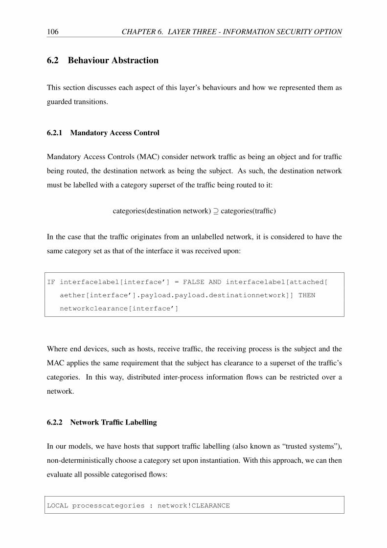
106 CHAPTER 6. LAYER THREE - INFORMATION SECURITY OPTION
6.2 Behaviour Abstraction
This section discusses each aspect of this layer’s behaviours and how we represented them as
guarded transitions.
6.2.1 Mandatory Access Control
Mandatory Access Controls (MAC) consider network traffic as being an object and for traffic
being routed, the destination network as being the subject. As such, the destination network
must be labelled with a category superset of the traffic being routed to it:
categories(destination network) ◆ categories(traffic)
In the case that the traffic originates from an unlabelled network, it is considered to have the
same category set as that of the interface it was received upon:
IF interfacelabel[interface’] = FALSE AND interfacelabel[attached[
aether[interface’].payload.payload.destinationnetwork]] THEN
networkclearance[interface’]
Where end devices, such as hosts, receive traffic, the receiving process is the subject and the
MAC applies the same requirement that the subject has clearance to a superset of the traffic’s
categories. In this way, distributed inter-process information flows can be restricted over a
network.
6.2.2 Network Traffic Labelling
In our models, we have hosts that support traffic labelling (also known as “trusted systems”),
non-deterministically choose a category set upon instantiation. With this approach, we can then
evaluate all possible categorised flows:
LOCAL processcategories : network!CLEARANCE

6.2. BEHAVIOUR ABSTRACTION 107
When a host that supports traffic labelling sends traffic, that traffic will be labelled with the
category set non-deterministically chosen at instantiation:
aether’[cable] = (# author := me, forwarder := topology!none, payload
:= (# source := sendfromphyhost, destination := sendtophyhost,
payload:= (# sourcenetwork := sendfromlognet, sourcehost :=
sendfromloghost, destinationnetwork := sendtolognet,
destinationhost := sendtologhost, label := processcategories #) #)
#);
Below are the local delivery, attached network, next-hop and default route transition guard
predicates with transition body in relation to Multi-Category Security (MCS). These predicates
ensure that labelled traffic is only processed on labelled networks and that that traffic’s category
set is a subset of the reception interface’s category clearance (i.e., according to the MCS policy).
In the body (the statement after each ->), can be seen the traffic labelling portion of the
transition.
local delivery:
((interfacelabel[a] = FALSE AND (FORALL (c : topology!CATEGORY) :
aether[a].payload.payload.label[c] = FALSE)) OR (interfacelabel[a]
AND (FORALL (c : topology!CATEGORY) : (NOT(aether[a].payload.
payload.label[c]) OR networkclearance[a][c]))))
directly attached:
((interfacelabel[a] = FALSE AND (FORALL (c : topology!CATEGORY) :
aether[a].payload.payload.label[c] = FALSE AND (NOT(
networkclearance[a][c]) OR networkclearance[resolv[aether[a].
payload.payload.destinationhost].interface][c]))) OR (
interfacelabel[a] AND (FORALL (c : topology!CATEGORY) : (NOT(
aether[a].payload.payload.label[c]) OR (networkclearance[a][c] AND
networkclearance[resolv[aether[a].payload.payload.destinationhost
].interface][c]))))) AND
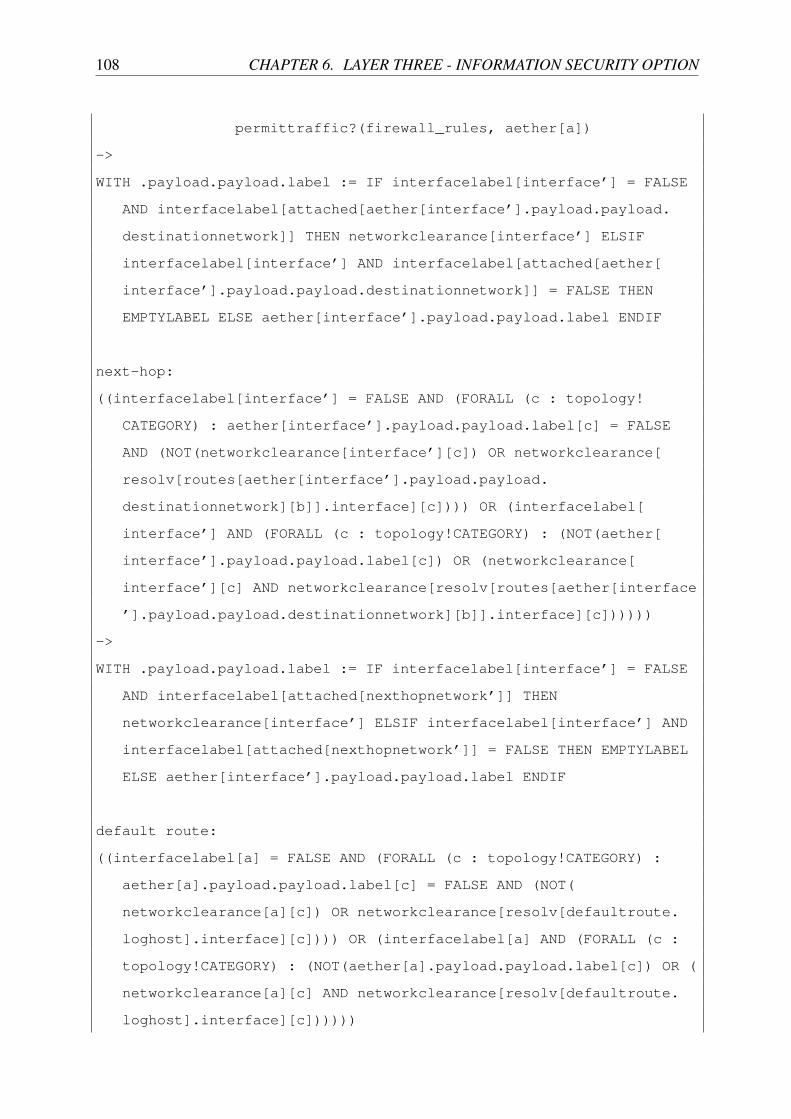
108 CHAPTER 6. LAYER THREE - INFORMATION SECURITY OPTION
permittraffic?(firewall_rules, aether[a])
->
WITH .payload.payload.label := IF interfacelabel[interface’] = FALSE
AND interfacelabel[attached[aether[interface’].payload.payload.
destinationnetwork]] THEN networkclearance[interface’] ELSIF
interfacelabel[interface’] AND interfacelabel[attached[aether[
interface’].payload.payload.destinationnetwork]] = FALSE THEN
EMPTYLABEL ELSE aether[interface’].payload.payload.label ENDIF
next-hop:
((interfacelabel[interface’] = FALSE AND (FORALL (c : topology!
CATEGORY) : aether[interface’].payload.payload.label[c] = FALSE
AND (NOT(networkclearance[interface’][c]) OR networkclearance[
resolv[routes[aether[interface’].payload.payload.
destinationnetwork][b]].interface][c]))) OR (interfacelabel[
interface’] AND (FORALL (c : topology!CATEGORY) : (NOT(aether[
interface’].payload.payload.label[c]) OR (networkclearance[
interface’][c] AND networkclearance[resolv[routes[aether[interface
’].payload.payload.destinationnetwork][b]].interface][c])))))
->
WITH .payload.payload.label := IF interfacelabel[interface’] = FALSE
AND interfacelabel[attached[nexthopnetwork’]] THEN
networkclearance[interface’] ELSIF interfacelabel[interface’] AND
interfacelabel[attached[nexthopnetwork’]] = FALSE THEN EMPTYLABEL
ELSE aether[interface’].payload.payload.label ENDIF
default route:
((interfacelabel[a] = FALSE AND (FORALL (c : topology!CATEGORY) :
aether[a].payload.payload.label[c] = FALSE AND (NOT(
networkclearance[a][c]) OR networkclearance[resolv[defaultroute.
loghost].interface][c]))) OR (interfacelabel[a] AND (FORALL (c :
topology!CATEGORY) : (NOT(aether[a].payload.payload.label[c]) OR (
networkclearance[a][c] AND networkclearance[resolv[defaultroute.
loghost].interface][c])))))

6.3. ANALYSIS 109
->
WITH .payload.payload.label := IF interfacelabel[interface’] = FALSE
AND interfacelabel[attached[defaultroute.lognet]] THEN
networkclearance[interface’] ELSIF interfacelabel[interface’] AND
interfacelabel[attached[defaultroute.lognet]] = FALSE THEN
EMPTYLABEL ELSE aether[interface’].payload.payload.label ENDIF
Routers are required to label traffic being routed to a labelled interface if that traffic originates
from an unlabelled interface and vice versa. This is from the body of the next-hop transition
and determines the correct label (or lack thereof) to give a message as it’s routed:
WITH .payload.payload.label := IF interfacelabel[interface’] = FALSE
AND interfacelabel[attached[nexthopnetwork’]] THEN
networkclearance[interface’] ELSIF interfacelabel[interface’] AND
interfacelabel[attached[nexthopnetwork’]] = FALSE THEN EMPTYLABEL
ELSE aether[interface’].payload.payload.label ENDIF
6.3 Analysis
In this section we examine Topology 7, seen in Figure 6.3 with a single router connected to
four trusted system hosts, each on their own network with no firewall. There are two labelled
networks and two unlabelled networks, and of them there are two with clearance to the c0
category and two without.
Each of the hosts has also been configured as a bad actor so that they will generate category
labelled traffic, irrespective of whether or not they should. For example, Carlos and Dave
actually represent networks of non-trusted system hosts (i.e. no traffic labelling) to model
communication between non-trusted and trusted system hosts. However, in order to exhaus-
tively check the router’s information label handling behaviours, we have chosen to instantiate
Carlos and Dave as trusted systems, but also as bad actors so they generate erroneous category

110 CHAPTER 6. LAYER THREE - INFORMATION SECURITY OPTION
Carlos
unlabelled { }
Dave
unlabelled {c0}
Alice
labelled { }
Bob
labelled {c0}
A B
C
D
Figure 6.3: Topology 7
labelled traffic on unlabelled networks. As with previous analysis sections, this topology has
been designed to facilitate the analysis of every behaviour introduced in this chapter in isolation.
With this arrangement, there are nine expected permissible flows of uncategorised traffic:
% Bob can send t o A l i c e
g r o u p 1 t e s t 1 4 f a l s e : THEOREM e x e c u t e |� G(NOT( a e t h e r [A ] . f o r w a r d e r =
r o u t e r AND a e t h e r [A ] . a u t h o r = bob AND a e t h e r [A ] . pay load . pay load .
l a b e l [ c0 ] = f a l s e ) ) ;
% Car lo s can send t o A l i c e
g r o u p 1 t e s t 2 4 f a l s e : THEOREM e x e c u t e |� G(NOT( a e t h e r [A ] . f o r w a r d e r =
r o u t e r AND a e t h e r [A ] . a u t h o r = c a r l o s AND a e t h e r [A ] . pay load .
pay load . l a b e l [ c0 ] = f a l s e ) ) ;
% A l i c e can send t o Bob

6.3. ANALYSIS 111
g r o u p 1 t e s t 3 4 f a l s e : THEOREM e x e c u t e |� G(NOT( a e t h e r [B ] . f o r w a r d e r =
r o u t e r AND a e t h e r [B ] . a u t h o r = a l i c e AND a e t h e r [B ] . pay load . pay load
. l a b e l [ c0 ] = f a l s e ) ) ;
% Car lo s can send t o Bob
g r o u p 1 t e s t 4 4 f a l s e : THEOREM e x e c u t e |� G(NOT( a e t h e r [B ] . f o r w a r d e r =
r o u t e r AND a e t h e r [B ] . a u t h o r = c a r l o s AND a e t h e r [B ] . pay load .
pay load . l a b e l [ c0 ] = f a l s e ) ) ;
% A l i c e can send t o C a r l o s
g r o u p 1 t e s t 5 4 f a l s e : THEOREM e x e c u t e |� G(NOT( a e t h e r [C ] . f o r w a r d e r =
r o u t e r AND a e t h e r [C ] . a u t h o r = a l i c e AND a e t h e r [C ] . pay load . pay load
. l a b e l [ c0 ] = f a l s e ) ) ;
% Bob can send t o C a r lo s
g r o u p 1 t e s t 6 4 f a l s e : THEOREM e x e c u t e |� G(NOT( a e t h e r [C ] . f o r w a r d e r =
r o u t e r AND a e t h e r [C ] . a u t h o r = bob AND a e t h e r [C ] . pay load . pay load .
l a b e l [ c0 ] = f a l s e ) ) ;
% A l i c e can send t o Dave
g r o u p 1 t e s t 7 4 f a l s e : THEOREM e x e c u t e |� G(NOT( a e t h e r [D ] . f o r w a r d e r =
r o u t e r AND a e t h e r [D ] . a u t h o r = a l i c e AND a e t h e r [D ] . pay load . pay load
. l a b e l [ c0 ] = f a l s e ) ) ;
% Bob can send t o Dave
g r o u p 1 t e s t 8 4 f a l s e : THEOREM e x e c u t e |� G(NOT( a e t h e r [D ] . f o r w a r d e r =
r o u t e r AND a e t h e r [D ] . a u t h o r = bob AND a e t h e r [D ] . pay load . pay load .
l a b e l [ c0 ] = f a l s e AND p r o c e s s c a t e g o r i e s . 1 . 1 . 2 [ c0 ] = f a l s e ) ) ;
% Car lo s can send t o Dave
g r o u p 1 t e s t 9 4 f a l s e : THEOREM e x e c u t e |� G(NOT( a e t h e r [D ] . f o r w a r d e r =
r o u t e r AND a e t h e r [D ] . a u t h o r = c a r l o s AND a e t h e r [D ] . pay load .
pay load . l a b e l [ c0 ] = f a l s e ) ) ;
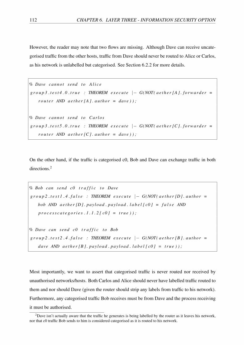
112 CHAPTER 6. LAYER THREE - INFORMATION SECURITY OPTION
However, the reader may note that two flows are missing. Although Dave can receive uncate-
gorised traffic from the other hosts, traffic from Dave should never be routed to Alice or Carlos,
as his network is unlabelled but categorised. See Section 6.2.2 for more details.
% Dave ca n n o t send t o A l i c e
g r o u p 3 t e s t 4 0 t r u e : THEOREM e x e c u t e |� G(NOT( a e t h e r [A ] . f o r w a r d e r =
r o u t e r AND a e t h e r [A ] . a u t h o r = dave ) ) ;
% Dave ca n n o t send t o C a r l o s
g r o u p 3 t e s t 5 0 t r u e : THEOREM e x e c u t e |� G(NOT( a e t h e r [C ] . f o r w a r d e r =
r o u t e r AND a e t h e r [C ] . a u t h o r = dave ) ) ;
On the other hand, if the traffic is categorised c0, Bob and Dave can exchange traffic in both
directions.2
% Bob can send c0 t r a f f i c t o Dave
g r o u p 2 t e s t 1 4 f a l s e : THEOREM e x e c u t e |� G(NOT( a e t h e r [D ] . a u t h o r =
bob AND a e t h e r [D ] . pay load . pay load . l a b e l [ c0 ] = f a l s e AND
p r o c e s s c a t e g o r i e s . 1 . 1 . 2 [ c0 ] = t r u e ) ) ;
% Dave can send c0 t r a f f i c t o Bob
g r o u p 2 t e s t 2 4 f a l s e : THEOREM e x e c u t e |� G(NOT( a e t h e r [B ] . a u t h o r =
dave AND a e t h e r [B ] . pay load . pay load . l a b e l [ c0 ] = t r u e ) ) ;
Most importantly, we want to assert that categorised traffic is never routed nor received by
unauthorised networks/hosts. Both Carlos and Alice should never have labelled traffic routed to
them and nor should Dave (given the router should strip any labels from traffic to his network).
Furthermore, any categorised traffic Bob receives must be from Dave and the process receiving
it must be authorised.2Dave isn’t actually aware that the traffic he generates is being labelled by the router as it leaves his network,
nor that c0 traffic Bob sends to him is considered categorised as it is routed to his network.

6.4. CASE STUDY THREE 113
% Car los can n e v e r r e c e i v e c a t e g o r i s e d t r a f f i c
g r o u p 3 t e s t 1 0 t r u e : THEOREM e x e c u t e |� G(NOT( a e t h e r [C ] . f o r w a r d e r =
r o u t e r AND a e t h e r [C ] . pay load . pay load . l a b e l [ c0 ] = t r u e ) ) ;
% A l i c e can n e v e r r e c e i v e c a t e g o r i s e d t r a f f i c
g r o u p 3 t e s t 2 0 t r u e : THEOREM e x e c u t e |� G(NOT( a e t h e r [A ] . f o r w a r d e r =
r o u t e r AND a e t h e r [A ] . pay load . pay load . l a b e l [ c0 ] = t r u e ) ) ;
% Dave can n e v e r r e c e i v e l a b e l l e d t r a f f i c
g r o u p 3 t e s t 3 0 t r u e : THEOREM e x e c u t e |� G(NOT( a e t h e r [D ] . f o r w a r d e r =
r o u t e r AND a e t h e r [D ] . pay load . pay load . l a b e l [ c0 ] = t r u e ) ) ;
% Any c a t e g o r i s e d t r a f f i c r o u t e d t o Bob c ann o t be from A l i c e nor
Ca r lo s
g r o u p 3 t e s t 6 0 t r u e : THEOREM e x e c u t e |� G(NOT( a e t h e r [B ] . f o r w a r d e r =
r o u t e r AND a e t h e r [B ] . pay load . pay load . l a b e l [ c0 ] = t r u e AND ( a e t h e r [
B ] . a u t h o r = a l i c e OR a e t h e r [B ] . a u t h o r = c a r l o s ) ) ) ;
% An u n a u t h o r i s e d p r o c e s s on Bob can n e v e r r e c e i v e c l a s s i f i e d t r a f f i c
g r o u p 4 t e s t 1 0 t r u e : THEOREM e x e c u t e |� G( p r o c e s s c a t e g o r i e s . 1 . 1 . 2 [ c0
] = f a l s e => r e c e i v e d . 1 . 1 . 2 . pay load . pay load . l a b e l [ c0 ] = f a l s e ) ;
This demonstrates that our abstraction of network traffic labelling and Mandatory Access
Control behaviour correctly processes labels and applies the Multi-Category Security policy’s
information-flow restrictions upon network traffic flows, respectively.
6.4 Case Study Three
Increasingly the intellectual property of organisations is at risk of theft from those with the
intention of gaining competitive advantage. The ubiquity and anonymity of the Internet means

114 CHAPTER 6. LAYER THREE - INFORMATION SECURITY OPTION
BastionHost
PublicHost
PrivateHost
Public Network DMZ Network Private Network
{c0} {c0,c1}
E T I
Figure 6.4: Topology 8
Table 6.1: Topology 8 - Permissible Inter-Network Flows
Network Public DMZ PrivatePublic ; ; ;DMZ ; {c0} {c0}Private ; {c0} {c0,c1}
that corporate espionage, or the theft of corporate secrets is now more prevalent and persistent
than it has ever been. If we are to mitigate the threat of corporate intellectual property being
leaked via the network, we must first identify the information, then put in place mechanisms
to restrict its flow. In this section we show how categorisation, network labels and Mandatory
Access Controls can be used together to mitigate this risk. We rigorously examine our suggested
approach by checking the properties of a common network topology model built using our
network device templates, then test it using existing real-world technologies.
Corporate networks are typically connected to the public Internet with an intermediary, so-
called “DMZ” network that has hardened “bastion” hosts with services provided to external
parties [42]. This structure is a common method used to isolate externally exposed and therefore
higher-risk services from internal services. The placement of a DMZ network varies, however
in this case study we use a DMZ network placed between the Public network (designed to mimic
the Internet) and a Private network. The DMZ and Private network are then considered separate
security domains, with hosts in the DMZ not typically allowed to initiate connections to hosts
in the Private network. This is done so that any externally accessible service in the DMZ that
may be compromised cannot access more sensitive services.

6.4. CASE STUDY THREE 115
Table 6.2: Topology 8 - Permissible Inter-Network Process Flows
Process Destination
Source
Public DMZ PrivatePublic ;, {}, {} {;, {c0}}, {}, {} {;, {c0}, {c0,c1}}, {}, {}DMZ ;, {}, {} {;, {c0}}, {c0}, {} {;, {c0}, {c0,c1}}, {{c0}, {c0,c1}}, {}Private ;, {}, {} {;, {c0}}, {c0}, {} {;, {c0}, {c0,c1}}, {{c0}, {c0,c1}}, {{c0,c1}}
In Table 6.1 we can see the permitted inter-network information-flows when the MCS policy
is applied to Topology 8, seen in Figure 6.43. In the first row and column we can see that
uncategorised traffic is free to flow between all networks. Between the categorised networks
(inside the organisation), we can see that {c0} traffic may flow, however it may not flow beyond
the DMZ network (out of the organisation). Finally, {c1} traffic is only permitted within the
Private network.
If we then consider every process category assignment possible in each network and every
permissible flow between them according to the MCS policy, we can enumerate all permissible
information-flows in the networks, as seen in Table 6.2. Each field in Table 6.2 contains an
ordered triple, where each coordinate represents a source process category set (;, {c0}, {c0,c1},
respectively), and holds permissible destination process category sets. In total, 15 permissible
flows are identified.
As with Table 6.1, in Table 6.2 we can see flows between uncategorised processes are able
to flow between all networks. Importantly, uncategorised traffic can flow up to categorised
processes, but not the other way. Furthermore, between the categorised networks, as a result
of the contiguous category ranges assigned, traffic can flow from {c0} processes in the DMZ
network to {c0,c1} processes in the Private network. In this way, an administrator has the ability
to assign categories to restrict process’ access to and the dissemination of information over the
network, according to a given organisational policy.
6.4.1 Threat
Our concern is with the dissemination of information in transit between networks and between
processes across networks. Here we assume that information is correctly categorised and
3Although each network segment (particularly the DMZ), by virtue of its multiple devices would have a layertwo bridge, we abstracted it out of the model as doing so significantly reduced the state-space but has no impacton the validity of our evaluation outcomes in this case study.

116 CHAPTER 6. LAYER THREE - INFORMATION SECURITY OPTION
labelled according to the prescription of this case study. The source of unauthorised information
dissemination in this setting can be classified into three categories: external bad actors, internal
bad actors and accidental dissemination. External bad actors (the principal threat we aim to
defend against) are those that reside outside the organisation and seek to exfiltrate categorised
information via the network. This could be attempted through a range of attack vectors, such as:
privilege escalation, vulnerability exploitation, malware, or a combination of these approaches.
Attacks targeting categorised information and the processeses that handle it are our focus here,
but integrity of the Mandatory Access Control that enforces the MCS information-flow policy
is assumed.
Unlike a Multi-Level Security (MLS) policy, the Multi-Category Security (MCS) policy
used here does not prevent a process from intentionally decategorising information (MCS equiv-
alent of MLS declassification), and so is not appropriate for mitigating the threat of inter-
nal bad actors with category clearance in this context. Our approach is however effective in
guarding against accidental categorised information dissemination as a result of software flaws,
misconfiguration and other human error on the part of developers, administrators, and users,
respectively.
6.4.2 Model
As per Section 6.1.2, below we can see the network labelling and clearance configuration for the
routers. The T (DMZ) network connection is labelled with clearance to c0 and the I (Private)
network connection is labelled with clearance to all categories (c0 and c1):
[[y : REALLINK] y = T OR y = I],
[[z : REALLINK] [[c : CATEGORY] (z = T AND c = c0) OR z = I]]]
First we start by examining every possible uncategorised traffic flow, with the expectation that
the three hosts should be able to communicate unabated. As with previous checks, this is done
through the use of negation to produce counter-examples:

6.4. CASE STUDY THREE 117
g r o u p 1 t e s t 1 9 f a l s e : THEOREM e x e c u t e |� G( r e c e i v e d . 1 . 1 . a u t h o r /=
p r i v a t e h o s t ) ;
g r o u p 1 t e s t 2 5 f a l s e : THEOREM e x e c u t e |� G( r e c e i v e d . 1 . 1 . a u t h o r /=
b a s t i o n h o s t ) ;
g r o u p 1 t e s t 3 5 f a l s e : THEOREM e x e c u t e |� G( r e c e i v e d . 1 . 2 . a u t h o r /=
p r i v a t e h o s t ) ;
g r o u p 1 t e s t 4 5 f a l s e : THEOREM e x e c u t e |� G( r e c e i v e d . 1 . 2 . a u t h o r /=
p u b l i c h o s t ) ;
g r o u p 1 t e s t 5 9 f a l s e : THEOREM e x e c u t e |� G( r e c e i v e d . 2 . a u t h o r /=
p u b l i c h o s t ) ;
g r o u p 1 t e s t 6 5 f a l s e : THEOREM e x e c u t e |� G( r e c e i v e d . 2 . a u t h o r /=
b a s t i o n h o s t ) ;
The DMZ and Private network hosts should be able to exchange c0 categorised flows:
g r o u p 2 t e s t 1 9 f a l s e : THEOREM e x e c u t e |� G(NOT( r e c e i v e d . 1 . 2 . a u t h o r =
p r i v a t e h o s t AND r e c e i v e d . 1 . 2 . pay load . pay load . l a b e l [ c0 ] ) ) ;
g r o u p 2 t e s t 2 9 f a l s e : THEOREM e x e c u t e |� G(NOT( r e c e i v e d . 2 . a u t h o r =
b a s t i o n h o s t AND r e c e i v e d . 2 . pay load . pay load . l a b e l [ c0 ] ) ) ;
However, categorised traffic should never flow down out of the organisation to the Public
network nor should c1 traffic leave the Private network:
% C a t e g o r i s e d t r a f f i c s h o u l d n o t f l o w down t o t h e p u b l i c ne twork
g r o u p 3 t e s t 1 1 2 t r u e : THEOREM e x e c u t e |� G( a e t h e r [E ] . f o r w a r d e r /=
none => NOT( a e t h e r [E ] . pay load . pay load . l a b e l [ c0 ] OR a e t h e r [E ] .
pay load . pay load . l a b e l [ c1 ] ) ) ;
% c1 c a t e g o r i s e d t r a f f i c s h o u l d n o t f l o w down t o t h e dmz ne twork
g r o u p 3 t e s t 2 1 2 t r u e : THEOREM e x e c u t e |� G( a e t h e r [ T ] . f o r w a r d e r /=
none => a e t h e r [ T ] . pay load . pay load . l a b e l [ c1 ] = f a l s e ) ;

118 CHAPTER 6. LAYER THREE - INFORMATION SECURITY OPTION
Under no circumstances should categorised traffic flow into the organisation and equally it
would be erroneous for c1 categoried traffic to be permitted to flow up from the DMZ to the
Private network:
% C a t e g o r i s e d t r a f f i c s h o u l d n e v e r be fo rwarded from t h e p u b l i c t o
t h e dmz ne twork
g r o u p 4 t e s t 1 1 2 t r u e : THEOREM e x e c u t e |� G( a e t h e r [ T ] . f o r w a r d e r =
e x t r o u t e r => NOT( a e t h e r [ T ] . pay load . pay load . l a b e l [ c0 ] OR a e t h e r [ T ] .
pay load . pay load . l a b e l [ c1 ] ) ) ;
% c1 c a t e g o r i s e d t r a f f i c s h o u l d n e v e r be fo rwarded from t h e dmz t o
t h e p r i v a t e ne twork
g r o u p 4 t e s t 2 1 2 t r u e : THEOREM e x e c u t e |� G( a e t h e r [ I ] . f o r w a r d e r /=
none => a e t h e r [ I ] . pay load . pay load . l a b e l [ c1 ] = f a l s e ) ;
Although a host may reside in a network with clearance to a category, the destination process
on that host may not and it is the responsibility of the Mandatory Access Control on the host to
prevent such processes from breaching the MCS policy. In this way, an uncategorised process
on the Bastion or Private hosts should be incapable of receiving c0 categorised traffic:
% An u n c a t e g o r i s e d p r o c e s s on t h e b a s t i o n h o s t can n e v e r r e c e i v e
c a t e g o r i s e d t r a f f i c
g r o u p 5 t e s t 1 1 2 t r u e : THEOREM e x e c u t e |� G( p r o c e s s c a t e g o r i e s . 1 . 2 [ c0 ]
= f a l s e => r e c e i v e d . 1 . 2 . pay load . pay load . l a b e l [ c0 ] = f a l s e ) ;
% A p r o c e s s w i t h o u t c0 c l e a r a n c e on t h e p r i v a t e h o s t can n e v e r
r e c e i v e c0 t r a f f i c
g r o u p 5 t e s t 2 1 2 t r u e : THEOREM e x e c u t e |� G( p r o c e s s c a t e g o r i e s . 2 [ c0 ] =
f a l s e => r e c e i v e d . 2 . pay load . pay load . l a b e l [ c0 ] = f a l s e ) ;

6.4. CASE STUDY THREE 119
6.4.3 Implementation
In this section we present an implementation of the previous section’s network and equivalent
tests to verify our findings from the previous section hold in a real environment. However, per-
forming these tests using enterprise-grade equipment would have required a significant amount
of hardware, so it was decided that virtualising the apparatus would simplify the implementa-
tion. Several consumer-grade hypervisors were considered, however VMWare Fusion was used
as it was the only hypervisor with the ability to provide the required three virtual networks.
In choosing an operating system for the virtual machines, the following were required:
• Mandatory Access Control (MAC)
• Information-Flow Policy Support
• Network Traffic Sensitivity Labelling Support
Some operating systems such as Mac OS X, have a Mandatory Access Control (MAC), but
do not support information-flow policies. Some operating systems such as FreeBSD have a
MAC with information-flow policy support but no support for network traffic labelling. Only
two groups of operating systems available to us were identified with all three requirements: Red
Hat-based Linux distributions since 20064 and Solaris (a traditional trusted operating system).
Red Hat Enterprise Linux (RHEL) 6 is currently widely used in industry and was initially
chosen, as it has an implementation of the de facto industry standard CIPSO [23] network
traffic sensitivity labelling protocol and SELinux MAC with MCS policy support. However, in
the first round of testing it was discovered that RHEL 6’s MCS policy applies to files, but not
labelled network traffic. We contacted Red Hat and they advised that the most current version
of their community-developed operating system Fedora (release 19) does apply the MCS policy
to labelled network traffic and so it was adopted in the place of RHEL5.
In the second round of testing, significant issues with the stability of Fedora’s networking
when labelled routing was enabled resulted in us using Solaris 10 (update 11) with Trusted
4MCS first appeared in Fedora Linux in 2006: http://james-morris.livejournal.com/5583.html
5Since performing these experiments, Red Hat has released RHEL 7, which does apply the MCS policy tolabelled network traffic, as it is based upon Fedora 19/20: https://access.redhat.com/articles/3078.

120 CHAPTER 6. LAYER THREE - INFORMATION SECURITY OPTION
Extensions for the routers. Solaris does not have a built-in MCS policy so we translated
SELinux’s MCS policy into Solaris’ equivalent label encodings6 file.
Solaris only has support for CIPSO tag type 17. As such, tag type 1 was used. Furthermore,
we used Solaris’ default Domain of Interpretation (DOI) of 1, which is used by a machine when
it receives labelled traffic to determine if the source is using the same information-flow policy.
These values do not directly affect the results, however it was important that those values were
consistent across all the machines, otherwise the traffic labels could not have been correctly
interpreted. Please see Appendix C for full configuration details.
Test Cases
The tests performed in this section are equivalent to the proofs examined in Section 6.4.2. The
utility ‘netcat’ (nc) was used on the three hosts with ‘runcon’ to create category assigned UDP
server and client sockets for each test case. It was necessary to use the connection-less transport
protocol UDP, as each of the test cases is designed to test uni-directional traffic flows.
The following was run on the destination host to receive traffic:
# runcon -l <destination level> nc -u -l <port>
The following was run on the source host to send traffic:
# runcon -l <source level> nc -u <destination> <port>
Table 6.3 shows each of the test cases, which were produced by enumerating all possible flows
between processes with every category set in each network according to Section 6.4.2. This
includes all of the 15 expected permissible flows from Table 6.2, and 7 expected blocked flows.
The test outcomes shown in Table 6.3 were gathered by running all 22 tests twice, which yielded
identical results.
6See Appendix B.7CIPSO tag types determine how sensitivity and category labels are encoded in IP headers, as per CIPSO
Internet Draft [23].

6.4. CASE STUDY THREE 121
Table 6.3: Case Study Three - Experimental Results
Test Source Destination FlowCase Host Level Host Level Result1 Public s0 Bastion s0 Allow2 s0:c0 Allow3 Private s0 Allow4 s0:c0 Allow5 s0:c0.c1 Allow6 Bastion s0 Public s0 Allow7 Private s0 Allow8 s0:c0 Allow9 s0:c0.c1 Allow10 s0:c0 Public s0 Block11 Private s0 Block12 s0:c0 Allow13 s0:c0.c1 Allow14 Private s0 Public s0 Allow15 Bastion s0 Allow16 s0:c0 Allow17 s0:c0 Public s0 Block18 Bastion s0 Block19 s0:c0 Allow20 s0:c0.c1 Public s0 Block21 Bastion s0 Block22 s0:c0 Block
With respect to categories, we can organise the test cases into 4 groups:
• Flows between uncategorised processes
• Flows between processes of the same category
• Flows to a process with a superset of the source
• Flows to a process with a subset of the source
Test cases 1, 3, 6, 7, 14 and 15 show uncategorised flows (equivalent to Section 6.4.2’s group 1
proofs) and test cases 12 and 19 show flows between processes of the same category set (equiv-
alent to Section 6.4.2’s group 2 proofs). These are relatively unremarkable, however, test cases

122 CHAPTER 6. LAYER THREE - INFORMATION SECURITY OPTION
2, 4, 5, 8, 9, 13 and 16 show flows from processes of lesser category sets to those of greater
category sets. Lastly, test cases 10, 11, 17, 18, 20, 21 and 22 show flows from processes with a
superset of the destination process (equivalent to Section 6.4.2’s group 3 and 5 proofs), and are
blocked, as per the MCS policy.
Flows such as those seen in test cases 20, 21 and 22 are blocked by the router between the
DMZ and Private network, as the DMZ network does not have clearance for {c1}. However,
although the Private network has clearance for {c0}, if a destination process in the Private
network does not have {c0} assigned, as seen in test case 11, the destination host’s operating
system will block the traffic. Through these tests, we have shown that the traffic flow predictions
made by our model in Section 6.4.2 were accurate.
6.5 Summary
In this chapter, we took the layer three abstraction produced in the preceding chapter and
expanded it to incorporate network information-flow controls based upon Mandatory Access
Controls and Commercial Internet Protocol Security Option (CIPSO) [23] traffic labelling.
After performing extensive behavioural checks in isolation, we then examined the composite
properties of a multi-hop inter-network using information-flow controls in Case Study Three.
With Case Study Three we applied the Multi-Category Security (MCS) policy in a hierar-
chical fashion to a typical corporate network topology, demonstrating with our models how
in the absence of other flow controls (such as firewalls), Mandatory Access Controls can be
used to significantly mitigate the risk of network-based information leakage. Our theoretical
demonstration was followed by an implementation of the proposed network configuration using
existing technologies, with findings that corroborate the soundness of both our modelling and
proposed use of network information-flow controls.

Chapter 7
Conclusion
In this thesis, we have taken the specifications for some of the most common protocols underpin-
ning modern computer networks and from them created finite-state models of their behaviour for
the purposes of safety property analysis. In Chapter 3, we produced a method for instantiating
devices from templates with parameters and representing the layer one physical topology of
a network with the capacity for message transmission between device models. Building upon
the physical network model of the preceding chapter, Chapter 4 introduced layer two physical
addressing and with it a bridge model template based on an IEEE standard. This model was
our first device template to demonstrate asynchronous stateful network behaviour in our finite-
state abstraction and accurately predicted a known spoofing attack. Our subsequent analysis in
Chapter 4’s Case Study One lead to the discovery of a behavioural logic flaw in the standard
that we rectified with a revised specification.
In Chapter 5 we expanded our models further to incorporate layer three logical addressing
and routing. Our router device model demonstrated how the complex interplay between layers
of protocols can be successfully represented in a finite-state model and in the process formalised
their specifications. It could be argued that on its own Topology 5 in Chapter 5 demonstrates that
we have been successful in our goal of accurately predicting the behaviours of networks in such
a way that their composite properties can be rigorously evaluated against a given specification.
However, we believe that would be to overlook that the physical topology and routing table
design of Topology 5 is a contribution itself in that they provide the means to examine any
and all routing behaviours. It is hoped that works that follow use Topology 5 in the same
way we used an existing work as the basis of Chapter 5’s Case Study Two to examine firewall
123

124 CHAPTER 7. CONCLUSION
misconfigurations.
Our layer three message abstraction was augmented in Chapter 6, along with the addition
of network information-flow controls to our router model. Case Study Three in Chapter 6
used these features to demonstrate with mathematical rigour how it’s possible in a corporate
environment to mitigate network-based information leakage. To further reinforce the validity
and practicality of our proposal, we then implemented Case Study Three’s network and ran
equivalent tests, yielding the results our model predicted.
Throughout this thesis we have developed our abstraction to incorporate only the most
essential of characteristics and although completely automated through the use of scripting, run-
ning 263 checks consumes six days of compute time and at its peak 35GB of memory, pushing
the boundaries of what is considered feasible with model checking. In spite of these challenges,
we believe our models could form the foundation of future application layer protocol analysis,
overcoming the limitations of existing literature where the network is highly abstracted.

Appendix A
Models
A.1 network.sal
network : CONTEXT =
BEGIN
HOST : TYPE = {u : topology!NODE | u /= topology!none AND u /= topology!broadcast};
LOGICALNETWORK : TYPE = {u : topology!LOGICALNETWORKADDR | u /= topology!null};
ACTION : TYPE = {ACCEPT, DISCARD};
ACL : TYPE = [# SRC_host : topology!NODE, SRC_net : topology!LOGICALNETWORKADDR, DST_host : topology!NODE,
DST_net : topology!LOGICALNETWORKADDR, action : ACTION #];
CLEARANCE : TYPE = ARRAY topology!CATEGORY OF BOOLEAN;
125

126APPEN
DIX
A.M
OD
ELS
DATAGRAM : TYPE = [# sourcenetwork : topology!LOGICALNETWORKADDR, sourcehost : topology!NODE,
destinationnetwork : topology!LOGICALNETWORKADDR, destinationhost : topology!NODE, label : CLEARANCE
#];
FRAME : TYPE = [# source : topology!NODE, destination : topology!NODE, payload : DATAGRAM #];
METAMESSAGE : TYPE = [# author : topology!NODE, forwarder : topology!NODE, payload : FRAME #];
REALLINK : TYPE = {a : topology!LINK | a /= topology!NA};
NETWORK : TYPE = ARRAY REALLINK OF METAMESSAGE;
NETWORKCLEARANCE : TYPE = ARRAY REALLINK OF CLEARANCE;
EMPTYLABEL : CLEARANCE = [[c : topology!CATEGORY] FALSE];
LABELPOLICY : TYPE = ARRAY REALLINK OF BOOLEAN;
ARPTABLE : TYPE = ARRAY topology!NODE OF [# phyaddr : topology!NODE, interface : topology!LINK #];
EMPTYMETAMESSAGE : METAMESSAGE = (# author := topology!none, forwarder := topology!none, payload := (#
source := topology!none, destination := topology!none, payload := (# sourcenetwork := topology!null,
sourcehost := topology!none, destinationnetwork := topology!null, destinationhost := topology!none,
label := EMPTYLABEL #) #) #);
establishconnections : MODULE =
BEGIN

A.2.H
OST.SAL
127
GLOBAL aether : NETWORK
INITIALIZATION
(FORALL (a : REALLINK) : aether[a] = EMPTYMETAMESSAGE)
END;
END
A.2 host.sal
host : CONTEXT =
BEGIN
IMPORTING network;
stateful [ me : HOST, cable : REALLINK, faulted : BOOLEAN, mylognet : topology!LOGICALNETWORKADDR,
nummsgstosend : nznat ] : MODULE =
BEGIN
LOCAL processcategories : network!CLEARANCE

128APPEN
DIX
A.M
OD
ELS
LOCAL received : METAMESSAGE
LOCAL numsgsent : [0..nummsgstosend]
LOCAL sendfromphyhost : {v : topology!CLIENT | faulted OR v = me}
LOCAL sendfromloghost : {v : topology!CLIENT | faulted OR v = me}
LOCAL sendfromlognet : {v : topology!LOGICALNETWORKADDR | v /= topology!null AND (faulted OR v = mylognet)
}
LOCAL sendtophyhost : {a : topology!NODE | a /= topology!none AND a /= me}
LOCAL sendtologhost : {a : topology!CLIENT | a /= me OR faulted}
LOCAL sendtolognet : {a : LOGICALNETWORK | TRUE}
GLOBAL aether : NETWORK
INITIALIZATION
numsgsent = 0;
received = EMPTYMETAMESSAGE;
(FORALL (c : topology!CATEGORY) : processcategories[c] = FALSE);
TRANSITION
[
send:
numsgsent < nummsgstosend AND aether[cable].author = topology!none
-->

A.2.H
OST.SAL
129
aether’[cable] = (# author := me, forwarder := topology!none, payload := (# source :=
sendfromphyhost, destination := sendtophyhost, payload:= (# sourcenetwork :=
sendfromlognet, sourcehost := sendfromloghost, destinationnetwork := sendtolognet,
destinationhost := sendtologhost, label := processcategories #) #) #);
numsgsent’ = numsgsent + 1;
sendfromphyhost’ IN {v : topology!CLIENT | faulted OR v = me};
sendfromloghost’ IN {v : topology!CLIENT | faulted OR v = me};
sendfromlognet’ IN {v : topology!LOGICALNETWORKADDR | v /= topology!null AND (faulted OR v
= mylognet)};
sendtophyhost’ IN {a : topology!NODE | a /= topology!none AND a /= me};
sendtologhost’ IN {a : topology!CLIENT | a /= me OR faulted};
sendtolognet’ IN {a : LOGICALNETWORK | TRUE}
[]
receive:
aether[cable].author /= topology!none AND
aether[cable].author /= me
-->
received’ = aether[cable];
aether’[cable] = EMPTYMETAMESSAGE

130APPEN
DIX
A.M
OD
ELS
]
END;
stateless [ me : HOST, cable : REALLINK, faulted : BOOLEAN, mylognet : topology!LOGICALNETWORKADDR,
nummsgstosend : nznat ] : MODULE =
BEGIN
LOCAL processcategories : network!CLEARANCE
LOCAL numsgsent : [0..nummsgstosend]
LOCAL sendfromphyhost : {v : topology!CLIENT | faulted OR v = me}
LOCAL sendfromloghost : {v : topology!CLIENT | faulted OR v = me}
LOCAL sendfromlognet : {v : topology!LOGICALNETWORKADDR | v /= topology!null AND (faulted OR v = mylognet)
}
LOCAL sendtophyhost : {a : topology!NODE | a /= topology!none AND a /= me}
LOCAL sendtologhost : {a : topology!CLIENT | a /= me OR faulted}
LOCAL sendtolognet : {a : LOGICALNETWORK | TRUE}
GLOBAL aether : NETWORK
INITIALIZATION
numsgsent = 0;
(FORALL (c : topology!CATEGORY) : processcategories[c] = FALSE);

A.2.H
OST.SAL
131
TRANSITION
[
send:
numsgsent < nummsgstosend AND aether[cable].author = topology!none
-->
aether’[cable] = (# author := me, forwarder := topology!none, payload := (# source :=
sendfromphyhost, destination := sendtophyhost, payload:= (# sourcenetwork :=
sendfromlognet, sourcehost := sendfromloghost, destinationnetwork := sendtolognet,
destinationhost := sendtologhost, label := processcategories #) #) #);
numsgsent’ = numsgsent + 1;
sendfromphyhost’ IN {v : topology!CLIENT | faulted OR v = me};
sendfromloghost’ IN {v : topology!CLIENT | faulted OR v = me};
sendfromlognet’ IN {v : topology!LOGICALNETWORKADDR | v /= topology!null AND (faulted OR v
= mylognet)};
sendtophyhost’ IN {a : topology!NODE | a /= topology!none AND a /= me};
sendtologhost’ IN {a : topology!CLIENT | a /= me OR faulted};
sendtolognet’ IN {a : LOGICALNETWORK | TRUE}
[]

132APPEN
DIX
A.M
OD
ELS
receive:
aether[cable].author /= topology!none AND
aether[cable].author /= me
-->
aether’[cable] = EMPTYMETAMESSAGE
]
END;
trustedsystem [ me : HOST, cable : REALLINK, faulted : BOOLEAN, mylognet : topology!LOGICALNETWORKADDR,
nummsgstosend : nznat ] : MODULE =
BEGIN
LOCAL processcategories : network!CLEARANCE
LOCAL received : METAMESSAGE
LOCAL numsgsent : [0..nummsgstosend]
LOCAL sendfromphyhost : {v : topology!CLIENT | faulted OR v = me}
LOCAL sendfromloghost : {v : topology!CLIENT | faulted OR v = me}
LOCAL sendfromlognet : {v : topology!LOGICALNETWORKADDR | v /= topology!null AND (faulted OR v = mylognet)
}
LOCAL sendtophyhost : {a : topology!NODE | a /= topology!none AND a /= me}

A.2.H
OST.SAL
133
LOCAL sendtologhost : {a : topology!CLIENT | a /= me OR faulted}
LOCAL sendtolognet : {a : LOGICALNETWORK | TRUE}
GLOBAL aether : NETWORK
INITIALIZATION
numsgsent = 0;
received = EMPTYMETAMESSAGE;
TRANSITION
[
send:
numsgsent < nummsgstosend AND aether[cable].author = topology!none
-->
aether’[cable] = (# author := me, forwarder := topology!none, payload := (# source :=
sendfromphyhost, destination := sendtophyhost, payload:= (# sourcenetwork :=
sendfromlognet, sourcehost := sendfromloghost, destinationnetwork := sendtolognet,
destinationhost := sendtologhost, label := processcategories #) #) #);
numsgsent’ = numsgsent + 1;
sendfromphyhost’ IN {v : topology!CLIENT | faulted OR v = me};
sendfromloghost’ IN {v : topology!CLIENT | faulted OR v = me};

134APPEN
DIX
A.M
OD
ELS
sendfromlognet’ IN {v : topology!LOGICALNETWORKADDR | v /= topology!null AND (faulted OR v
= mylognet)};
sendtophyhost’ IN {a : topology!NODE | a /= topology!none AND a /= me};
sendtologhost’ IN {a : topology!CLIENT | a /= me OR faulted};
sendtolognet’ IN {a : LOGICALNETWORK | TRUE}
[]
receive:
aether[cable].author /= topology!none AND
aether[cable].author /= me AND
(FORALL (c : topology!CATEGORY) : (NOT(aether[cable].payload.payload.label[c]) OR
processcategories[c]))
-->
received’ = aether[cable];
aether’[cable] = EMPTYMETAMESSAGE
]
END;
END

A.3.REPEATER.SAL
135
A.3 repeater.sal
repeater : CONTEXT =
BEGIN
IMPORTING network;
messagewaiting?(me : HOST, msg : METAMESSAGE) : BOOLEAN =
msg.author /= topology!none AND
msg.author /= me AND
msg.forwarder /= me;
repeater [me : HOST, cable : ARRAY REALLINK OF BOOLEAN] : MODULE =
BEGIN
LOCAL interface : topology!LINK
GLOBAL aether : NETWORK
INITIALIZATION
interface = topology!NA
TRANSITION
[

136APPEN
DIX
A.M
OD
ELS
propagate:
TRUE
-->
interface’ IN {a : REALLINK |
cable[a] AND
messagewaiting?(me, aether[a])};
(FORALL (j : {v : REALLINK | cable[v]}) : aether’[j] = (IF j /= interface’ THEN (aether[
interface’] WITH .forwarder := me) ELSE EMPTYMETAMESSAGE ENDIF));
]
END;
END
A.4 bridge.sal
bridge : CONTEXT =

A.4.BRID
GE.SAL
137
BEGIN
IMPORTING network;
LEARNTYPE : TYPE = {empty, static, dynamic};
FILTERINGENTRY : TYPE = [# acquisition: LEARNTYPE, interface : topology!LINK #];
LOOKUPTABLE : TYPE = ARRAY HOST OF FILTERINGENTRY;
messagewaiting?(me : HOST, msg : METAMESSAGE) : BOOLEAN =
msg.author /= topology!none AND
msg.author /= me AND
msg.forwarder /= me;
validmessage?(me : HOST, msg : METAMESSAGE) : BOOLEAN =
msg.payload.source /= me AND
msg.payload.destination /= me AND
msg.payload.source /= msg.payload.destination;
IEEE8021D04 [me : HOST, cable : ARRAY REALLINK OF BOOLEAN, staticentries : ARRAY HOST OF REALLINK] :
MODULE =
BEGIN

138APPEN
DIX
A.M
OD
ELS
LOCAL filteringdatabase : LOOKUPTABLE
LOCAL interface : topology!LINK
GLOBAL aether : NETWORK
INITIALIZATION
(FORALL (j : HOST) :
filteringdatabase[j] =
IF staticentries[j] = topology!NA THEN
(# acquisition := empty, interface := topology!NA #)
ELSE
(# acquisition := static, interface := staticentries[j] #)
ENDIF);
interface = topology!NA
TRANSITION
[
unicast:
TRUE
-->
interface’ IN {a : REALLINK |
cable[a] AND

A.4.BRID
GE.SAL
139
messagewaiting?(me, aether[a]) AND
validmessage?(me, aether[a]) AND
filteringdatabase[aether[a].payload.destination].interface /= topology!NA AND
filteringdatabase[aether[a].payload.destination].interface /= a};
filteringdatabase’ = IF filteringdatabase[aether[interface’].payload.source].acquisition =
static THEN
filteringdatabase
ELSE
(filteringdatabase WITH [aether[interface’].payload.source].acquisition := dynamic
) WITH [aether[interface’].payload.source].interface := interface’
ENDIF;
aether’ = (aether WITH [filteringdatabase[aether[interface’].payload.destination].
interface] := (aether[interface’] WITH .forwarder := me)) WITH [interface’] :=
EMPTYMETAMESSAGE;
[]
broadcast:
TRUE
-->

140APPEN
DIX
A.M
OD
ELS
interface’ IN {a : REALLINK |
cable[a] AND
messagewaiting?(me, aether[a]) AND
validmessage?(me, aether[a]) AND
(aether[a].payload.destination = topology!broadcast OR
filteringdatabase[aether[a].payload.destination].interface = topology!NA)};
filteringdatabase’ = IF filteringdatabase[aether[interface’].payload.source].acquisition =
static THEN
filteringdatabase
ELSE
(filteringdatabase WITH [aether[interface’].payload.source].acquisition := dynamic
) WITH [aether[interface’].payload.source].interface := interface’
ENDIF;
(FORALL (j : {v : REALLINK | cable[v]}) : aether’[j] = (IF j /= interface’ THEN (aether[
interface’] WITH .forwarder := me) ELSE EMPTYMETAMESSAGE ENDIF));
[]
discard:
TRUE
-->

A.4.BRID
GE.SAL
141
interface’ IN {a : REALLINK |
cable[a] AND
messagewaiting?(me, aether[a]) AND
aether[a].forwarder /= me AND
((NOT(validmessage?(me, aether[a]))) OR
filteringdatabase[aether[a].payload.destination].interface = a)};
filteringdatabase’ = IF aether[interface’].payload.source /= me AND filteringdatabase[
aether[interface’].payload.source].acquisition /= static THEN
(filteringdatabase WITH [aether[interface’].payload.source].acquisition := dynamic
) WITH [aether[interface’].payload.source].interface := interface’
ELSE
filteringdatabase
ENDIF;
aether’[interface’] = EMPTYMETAMESSAGE;
]
END;
proposed [me : HOST, cable : ARRAY REALLINK OF BOOLEAN, staticentries : ARRAY HOST OF REALLINK] : MODULE =

142APPEN
DIX
A.M
OD
ELS
BEGIN
LOCAL filteringdatabase : LOOKUPTABLE
LOCAL interface : topology!LINK
GLOBAL aether : NETWORK
INITIALIZATION
(FORALL (j : HOST) :
filteringdatabase[j] =
IF staticentries[j] = topology!NA THEN
(# acquisition := empty, interface := topology!NA #)
ELSE
(# acquisition := static, interface := staticentries[j] #)
ENDIF);
interface = topology!NA
TRANSITION
[
unicast:
TRUE
-->

A.4.BRID
GE.SAL
143
interface’ IN {a : REALLINK |
cable[a] AND
messagewaiting?(me, aether[a]) AND
validmessage?(me, aether[a]) AND
(filteringdatabase[aether[a].payload.source].acquisition /= static OR (filteringdatabase[
aether[a].payload.source].acquisition = static AND a = filteringdatabase[aether[a].
payload.source].interface)) AND
filteringdatabase[aether[a].payload.destination].interface /= topology!NA AND
filteringdatabase[aether[a].payload.destination].interface /= a};
filteringdatabase’ = IF filteringdatabase[aether[interface’].payload.source].acquisition =
static THEN
filteringdatabase
ELSE
(filteringdatabase WITH [aether[interface’].payload.source].acquisition := dynamic
) WITH [aether[interface’].payload.source].interface := interface’
ENDIF;
aether’ = (aether WITH [filteringdatabase[aether[interface’].payload.destination].
interface] := (aether[interface’] WITH .forwarder := me)) WITH [interface’] :=
EMPTYMETAMESSAGE;

144APPEN
DIX
A.M
OD
ELS
[]
broadcast:
TRUE
-->
interface’ IN {a : REALLINK |
cable[a] AND
messagewaiting?(me, aether[a]) AND
validmessage?(me, aether[a]) AND
(filteringdatabase[aether[a].payload.source].acquisition /= static OR (filteringdatabase[
aether[a].payload.source].acquisition = static AND a = filteringdatabase[aether[a].
payload.source].interface)) AND
(aether[a].payload.destination = topology!broadcast OR
filteringdatabase[aether[a].payload.destination].interface = topology!NA)};
filteringdatabase’ = IF filteringdatabase[aether[interface’].payload.source].acquisition =
static THEN
filteringdatabase
ELSE
(filteringdatabase WITH [aether[interface’].payload.source].acquisition := dynamic
) WITH [aether[interface’].payload.source].interface := interface’
ENDIF;

A.4.BRID
GE.SAL
145
(FORALL (j : {v : REALLINK | cable[v]}) : aether’[j] = (IF j /= interface’ THEN (aether[
interface’] WITH .forwarder := me) ELSE EMPTYMETAMESSAGE ENDIF));
[]
discard:
TRUE
-->
interface’ IN {a : REALLINK |
cable[a] AND
messagewaiting?(me, aether[a]) AND
aether[a].forwarder /= me AND
((NOT(validmessage?(me, aether[a]))) OR
filteringdatabase[aether[a].payload.destination].interface = a OR
(filteringdatabase[aether[a].payload.source].acquisition = static AND a /=
filteringdatabase[aether[a].payload.source].interface))};
filteringdatabase’ = IF aether[interface’].payload.source /= me AND
filteringdatabase[aether[interface’].payload.source].acquisition /= static THEN
(filteringdatabase WITH [aether[interface’].payload.source].acquisition := dynamic
) WITH [aether[interface’].payload.source].interface := interface’

146APPEN
DIX
A.M
OD
ELS
ELSE
filteringdatabase
ENDIF;
aether’[interface’] = EMPTYMETAMESSAGE;
]
END;
END
A.5 router.sal
router : CONTEXT =
BEGIN
IMPORTING network;
sourcenetworkvalid(receptioninterface : REALLINK, attached : ARRAY LOGICALNETWORK OF topology!LINK, routes
: ARRAY LOGICALNETWORK OF ARRAY LOGICALNETWORK OF topology!NODE, defaultroute : [# lognet : topology!
LOGICALNETWORKADDR, loghost : topology!NODE #], aether : NETWORK) : BOOLEAN =

A.5.RO
UTER.SAL
147
receptioninterface = attached[aether[receptioninterface].payload.payload.sourcenetwork] OR
(EXISTS (c : LOGICALNETWORK) : routes[aether[receptioninterface].payload.payload.sourcenetwork][c]
/= topology!none AND receptioninterface = attached[c]) OR
(receptioninterface = attached[defaultroute.lognet] AND attached[aether[receptioninterface].
payload.payload.sourcenetwork] = topology!NA AND NOT (EXISTS (c : LOGICALNETWORK) : routes[
aether[receptioninterface].payload.payload.sourcenetwork][c] /= topology!none AND
receptioninterface = attached[c]));
arprequest?(me : HOST, msg : METAMESSAGE, interface : REALLINK, attached : ARRAY LOGICALNETWORK OF
topology!LINK) : BOOLEAN =
msg.payload.source /= me AND
msg.payload.source /= topology!broadcast AND
msg.payload.destination = topology!broadcast AND
msg.payload.payload.destinationhost = me AND
attached[msg.payload.payload.destinationnetwork] = interface AND
msg.payload.payload.sourcehost /= me AND
msg.payload.payload.sourcenetwork = msg.payload.payload.destinationnetwork;
messagewaiting?(me : HOST, msg : METAMESSAGE) : BOOLEAN =
msg.author /= topology!none AND
msg.author /= me AND
msg.forwarder /= me;

148APPEN
DIX
A.M
OD
ELS
validmessage?(me : HOST, msg : METAMESSAGE, attached : ARRAY LOGICALNETWORK OF topology!LINK) : BOOLEAN =
msg.payload.source /= me AND
(msg.payload.destination = me OR
msg.payload.destination = topology!broadcast) AND
msg.payload.source /= msg.payload.destination AND
IF attached[msg.payload.payload.sourcenetwork] /= topology!NA THEN
msg.payload.payload.sourcehost /= me ELSE TRUE ENDIF;
permittraffic?(firewall_rules : ARRAY topology!FIREWALLSIZE OF ACL, msg : METAMESSAGE) : BOOLEAN =
EXISTS (r : topology!FIREWALLSIZE) : (firewall_rules[r].action = ACCEPT AND
( (firewall_rules[r].SRC_host = topology!none AND
(firewall_rules[r].SRC_net = msg.payload.payload.sourcenetwork OR firewall_rules[r
].SRC_net = topology!null))
OR
(firewall_rules[r].SRC_host = msg.payload.payload.sourcehost AND firewall_rules[r].
SRC_net = msg.payload.payload.sourcenetwork)
)
AND
( (firewall_rules[r].DST_host = topology!none AND

A.5.RO
UTER.SAL
149
(firewall_rules[r].DST_net = msg.payload.payload.destinationnetwork OR
firewall_rules[r].DST_net = topology!null))
OR
(firewall_rules[r].DST_host = msg.payload.payload.destinationhost AND firewall_rules[r].
DST_net = msg.payload.payload.destinationnetwork)
)
AND NOT (EXISTS (f : topology!FIREWALLSIZE) : (firewall_rules[f].action = DISCARD AND
( (firewall_rules[f].SRC_host = topology!none AND
(firewall_rules[f].SRC_net = msg.payload.payload.sourcenetwork OR
firewall_rules[f].SRC_net = topology!null))
OR
(firewall_rules[f].SRC_host = msg.payload.payload.sourcehost AND firewall_rules[f
].SRC_net = msg.payload.payload.sourcenetwork)
)
AND
( (firewall_rules[f].DST_host = topology!none AND
(firewall_rules[f].DST_net = msg.payload.payload.destinationnetwork OR
firewall_rules[f].DST_net = topology!null))
OR

150APPEN
DIX
A.M
OD
ELS
(firewall_rules[f].DST_host = msg.payload.payload.destinationhost AND
firewall_rules[f].DST_net = msg.payload.payload.destinationnetwork)
)
AND f < r)));
router [me : HOST, donotchecksource : BOOLEAN, cable : ARRAY REALLINK OF BOOLEAN, attached : ARRAY
LOGICALNETWORK OF topology!LINK, routes : ARRAY LOGICALNETWORK OF ARRAY LOGICALNETWORK OF topology!NODE
, defaultroute : [# lognet : topology!LOGICALNETWORKADDR, loghost : topology!NODE #], firewall_rules :
ARRAY topology!FIREWALLSIZE OF ACL, interfacelabel : LABELPOLICY, networkclearance : NETWORKCLEARANCE]
: MODULE =
BEGIN
LOCAL resolv : ARPTABLE
LOCAL interface : topology!LINK
LOCAL nexthopnetwork : topology!LOGICALNETWORKADDR
LOCAL resolvaddr : topology!NODE
GLOBAL aether : NETWORK
INITIALIZATION
resolv = [[p : topology!NODE] (# phyaddr := topology!none, interface := topology!NA #)];
interface = topology!NA;
nexthopnetwork = topology!null;

A.5.RO
UTER.SAL
151
resolvaddr = topology!none
TRANSITION
[
sendARPresponse:
TRUE
-->
interface’ IN {a : REALLINK |
cable[a] AND
messagewaiting?(me, aether[a]) AND
arprequest?(me, aether[a], a, attached)};
resolv’[aether[interface’].payload.payload.sourcehost] =
IF attached[aether[interface’].payload.payload.sourcenetwork] = interface’ THEN
(# phyaddr := aether[interface’].payload.source, interface := interface’
#)
ELSE
resolv[aether[interface’].payload.payload.sourcehost]
ENDIF;

152APPEN
DIX
A.M
OD
ELS
aether’ = aether WITH [interface’] := (((((((EMPTYMETAMESSAGE WITH .author := me) WITH .
payload.source := me) WITH .payload.destination := aether[interface’].payload.source)
WITH .payload.payload.sourcenetwork := aether[interface’].payload.payload.sourcenetwork
) WITH .payload.payload.sourcehost := me) WITH .payload.payload.destinationnetwork :=
aether[interface’].payload.payload.destinationnetwork) WITH .payload.payload.
destinationhost := aether[interface’].payload.payload.sourcehost)
[]
sendARPtoresolvenexthop:
TRUE
-->
interface’ IN {a : REALLINK |
cable[a] AND
messagewaiting?(me, aether[a]) AND
validmessage?(me, aether[a], attached) AND
aether[a].payload.destination /= topology!broadcast AND
aether[a].payload.payload.destinationhost /= me AND
aether[a].payload.payload.destinationhost /= topology!broadcast AND
attached[aether[a].payload.payload.destinationnetwork] = topology!NA AND
(EXISTS (b : LOGICALNETWORK) :
routes[aether[a].payload.payload.destinationnetwork][b] /= topology!none) AND
(FORALL (c : LOGICALNETWORK) :

A.5.RO
UTER.SAL
153
routes[aether[a].payload.payload.destinationnetwork][c] /= topology!none =>
resolv[routes[aether[a].payload.payload.destinationnetwork][c]].interface
/= attached[c] AND aether[attached[c]].payload.payload.sourcehost /=
routes[aether[a].payload.payload.destinationnetwork][c]) AND
(sourcenetworkvalid(a, attached, routes, defaultroute, aether) OR donotchecksource)};
nexthopnetwork’ IN {b : LOGICALNETWORK |
routes[aether[interface’].payload.payload.destinationnetwork][b] /= topology!none AND
(resolv[routes[aether[interface’].payload.payload.destinationnetwork][b]].phyaddr =
topology!none OR (resolv[routes[aether[interface’].payload.payload.destinationnetwork][
b]].phyaddr /= topology!none AND resolv[routes[aether[interface’].payload.payload.
destinationnetwork][b]].interface /= attached[b])) AND
aether[attached[b]].payload.source /= me AND
aether[attached[b]].payload.destination /= topology!broadcast AND
aether[attached[b]].payload.payload.destinationhost /= routes[aether[interface’].payload.
payload.destinationnetwork][b] AND
aether[attached[b]].payload.payload.destinationnetwork /= b AND
aether[attached[b]].payload.payload.sourcehost /= me AND
aether[attached[b]].payload.payload.sourcenetwork /= b};

154APPEN
DIX
A.M
OD
ELS
aether’ = aether WITH [attached[nexthopnetwork’]] := (((((((EMPTYMETAMESSAGE WITH .author
:= me) WITH .payload.source := me) WITH .payload.destination := topology!broadcast)
WITH .payload.payload.sourcenetwork := nexthopnetwork’) WITH .payload.payload.
sourcehost := me) WITH .payload.payload.destinationnetwork := nexthopnetwork’) WITH .
payload.payload.destinationhost := routes[aether[interface’].payload.payload.
destinationnetwork][nexthopnetwork’])
[]
sendARPtoresolvedefaultroute:
defaultroute.lognet /= topology!null
-->
interface’ IN {a : REALLINK |
cable[a] AND
messagewaiting?(me, aether[a]) AND
validmessage?(me, aether[a], attached) AND
aether[a].payload.destination /= topology!broadcast AND
aether[a].payload.payload.destinationhost /= me AND
aether[a].payload.payload.destinationhost /= topology!broadcast AND
attached[defaultroute.lognet] /= resolv[defaultroute.loghost].interface AND
attached[aether[a].payload.payload.destinationnetwork] = topology!NA AND
(FORALL (b : LOGICALNETWORK) :
routes[aether[a].payload.payload.destinationnetwork][b] = topology!none) AND

A.5.RO
UTER.SAL
155
aether[attached[defaultroute.lognet]].payload.source /= me AND
aether[attached[defaultroute.lognet]].payload.destination /= topology!broadcast AND
aether[attached[defaultroute.lognet]].payload.payload.destinationhost /= defaultroute.
loghost AND
aether[attached[defaultroute.lognet]].payload.payload.destinationnetwork /= defaultroute.
lognet AND
aether[attached[defaultroute.lognet]].payload.payload.sourcehost /= me AND
aether[attached[defaultroute.lognet]].payload.payload.sourcenetwork /= defaultroute.lognet
AND
aether[attached[defaultroute.lognet]].payload.payload.sourcehost /= defaultroute.loghost
AND
(sourcenetworkvalid(a, attached, routes, defaultroute, aether) OR donotchecksource)};
aether’ = aether WITH [attached[defaultroute.lognet]] := (((((((EMPTYMETAMESSAGE WITH .
author := me) WITH .payload.source := me) WITH .payload.destination := topology!
broadcast) WITH .payload.payload.sourcenetwork := defaultroute.lognet) WITH .payload.
payload.sourcehost := me) WITH .payload.payload.destinationnetwork := defaultroute.
lognet) WITH .payload.payload.destinationhost := defaultroute.loghost)

156APPEN
DIX
A.M
OD
ELS
[]
localdelivery:
TRUE
-->
interface’ IN {a : REALLINK |
cable[a] AND
messagewaiting?(me, aether[a]) AND
validmessage?(me, aether[a], attached) AND
NOT(arprequest?(me, aether[a], a, attached)) AND
attached[aether[a].payload.payload.destinationnetwork] /= topology!NA AND
(aether[a].payload.payload.destinationhost = me OR
aether[a].payload.payload.destinationhost = topology!broadcast) AND
(sourcenetworkvalid(a, attached, routes, defaultroute, aether) OR donotchecksource) AND
((interfacelabel[a] = FALSE AND (FORALL (c : topology!CATEGORY) : aether[a].payload.
payload.label[c] = FALSE)) OR (interfacelabel[a] AND (FORALL (c : topology!CATEGORY) :
(NOT(aether[a].payload.payload.label[c]) OR networkclearance[a][c]))))};
resolv’[aether[interface’].payload.payload.sourcehost] =
IF attached[aether[interface’].payload.payload.sourcenetwork] = interface’ THEN
(# phyaddr := aether[interface’].payload.source, interface := interface’
#)
ELSE

A.5.RO
UTER.SAL
157
resolv[aether[interface’].payload.payload.sourcehost]
ENDIF;
aether’[interface’] = EMPTYMETAMESSAGE
[]
directlyattachedroute:
TRUE
-->
interface’ IN {a : REALLINK |
cable[a] AND
messagewaiting?(me, aether[a]) AND
validmessage?(me, aether[a], attached) AND
aether[a].payload.destination /= topology!broadcast AND
attached[aether[a].payload.payload.destinationnetwork] /= topology!NA AND
aether[a].payload.payload.destinationhost /= me AND
aether[a].payload.payload.destinationhost /= topology!broadcast AND
resolv[aether[a].payload.payload.destinationhost].phyaddr /= topology!none AND
resolv[aether[a].payload.payload.destinationhost].interface = attached[aether[a].payload.
payload.destinationnetwork] AND
(sourcenetworkvalid(a, attached, routes, defaultroute, aether) OR donotchecksource) AND

158APPEN
DIX
A.M
OD
ELS
((interfacelabel[a] = FALSE AND (FORALL (c : topology!CATEGORY) : aether[a].payload.
payload.label[c] = FALSE AND (NOT(networkclearance[a][c]) OR networkclearance[resolv[
aether[a].payload.payload.destinationhost].interface][c]))) OR (interfacelabel[a] AND (
FORALL (c : topology!CATEGORY) : (NOT(aether[a].payload.payload.label[c]) OR (
networkclearance[a][c] AND networkclearance[resolv[aether[a].payload.payload.
destinationhost].interface][c]))))) AND
permittraffic?(firewall_rules, aether[a])};
resolv’[aether[interface’].payload.payload.sourcehost] =
IF attached[aether[interface’].payload.payload.sourcenetwork] = interface’ THEN
(# phyaddr := aether[interface’].payload.source, interface := interface’
#)
ELSE
resolv[aether[interface’].payload.payload.sourcehost]
ENDIF;

A.5.RO
UTER.SAL
159
aether’ = (aether WITH [attached[aether[interface’].payload.payload.destinationnetwork]]
:= ((((aether[interface’] WITH .forwarder := me) WITH .payload.source := me) WITH .
payload.destination := resolv[aether[interface’].payload.payload.destinationhost].
phyaddr) WITH .payload.payload.label := IF interfacelabel[interface’] = FALSE AND
interfacelabel[attached[aether[interface’].payload.payload.destinationnetwork]] THEN
networkclearance[interface’] ELSIF interfacelabel[interface’] AND interfacelabel[
attached[aether[interface’].payload.payload.destinationnetwork]] = FALSE THEN
EMPTYLABEL ELSE aether[interface’].payload.payload.label ENDIF)) WITH [interface’] :=
EMPTYMETAMESSAGE
[]
nexthoproute:
TRUE
-->
interface’ IN {a : REALLINK |
cable[a] AND
messagewaiting?(me, aether[a]) AND
validmessage?(me, aether[a], attached) AND
aether[a].payload.destination /= topology!broadcast AND
aether[a].payload.payload.destinationhost /= me AND
aether[a].payload.payload.destinationhost /= topology!broadcast AND

160APPEN
DIX
A.M
OD
ELS
(EXISTS (b : LOGICALNETWORK) : resolv[routes[aether[a].payload.payload.destinationnetwork
][b]].phyaddr /= topology!none) AND
(sourcenetworkvalid(a, attached, routes, defaultroute, aether) OR donotchecksource) AND
permittraffic?(firewall_rules, aether[a])};
nexthopnetwork’ IN {b : LOGICALNETWORK |
resolv[routes[aether[interface’].payload.payload.destinationnetwork][b]].phyaddr /=
topology!none AND resolv[routes[aether[interface’].payload.payload.destinationnetwork][
b]].interface = attached[b] AND
((interfacelabel[interface’] = FALSE AND (FORALL (c : topology!CATEGORY) : aether[
interface’].payload.payload.label[c] = FALSE AND (NOT(networkclearance[interface’][c])
OR networkclearance[resolv[routes[aether[interface’].payload.payload.destinationnetwork
][b]].interface][c]))) OR (interfacelabel[interface’] AND (FORALL (c : topology!
CATEGORY) : (NOT(aether[interface’].payload.payload.label[c]) OR (networkclearance[
interface’][c] AND networkclearance[resolv[routes[aether[interface’].payload.payload.
destinationnetwork][b]].interface][c])))))};
resolv’[aether[interface’].payload.payload.sourcehost] =
IF attached[aether[interface’].payload.payload.sourcenetwork] = interface’ THEN
(# phyaddr := aether[interface’].payload.source, interface := interface’
#)
ELSE

A.5.RO
UTER.SAL
161
resolv[aether[interface’].payload.payload.sourcehost]
ENDIF;
aether’ = (aether WITH [attached[nexthopnetwork’]] := ((((aether[interface’] WITH .
forwarder := me) WITH .payload.source := me) WITH .payload.destination := resolv[routes
[aether[interface’].payload.payload.destinationnetwork][nexthopnetwork’]].phyaddr) WITH
.payload.payload.label := IF interfacelabel[interface’] = FALSE AND interfacelabel[
attached[nexthopnetwork’]] THEN networkclearance[interface’] ELSIF interfacelabel[
interface’] AND interfacelabel[attached[nexthopnetwork’]] = FALSE THEN EMPTYLABEL ELSE
aether[interface’].payload.payload.label ENDIF)) WITH [interface’] := EMPTYMETAMESSAGE
[]
default:
defaultroute.lognet /= topology!null
-->
interface’ IN {a : REALLINK |
cable[a] AND
messagewaiting?(me, aether[a]) AND
validmessage?(me, aether[a], attached) AND
aether[a].payload.destination /= topology!broadcast AND
attached[aether[a].payload.payload.destinationnetwork] = topology!NA AND
(FORALL (b : LOGICALNETWORK) :

162APPEN
DIX
A.M
OD
ELS
routes[aether[a].payload.payload.destinationnetwork][b] = topology!none) AND
aether[a].payload.payload.destinationhost /= me AND
aether[a].payload.payload.destinationhost /= topology!broadcast AND
(sourcenetworkvalid(a, attached, routes, defaultroute, aether) OR donotchecksource) AND
resolv[defaultroute.loghost].interface = attached[defaultroute.lognet] AND
((interfacelabel[a] = FALSE AND (FORALL (c : topology!CATEGORY) : aether[a].payload.
payload.label[c] = FALSE AND (NOT(networkclearance[a][c]) OR networkclearance[resolv[
defaultroute.loghost].interface][c]))) OR (interfacelabel[a] AND (FORALL (c : topology!
CATEGORY) : (NOT(aether[a].payload.payload.label[c]) OR (networkclearance[a][c] AND
networkclearance[resolv[defaultroute.loghost].interface][c]))))) AND
permittraffic?(firewall_rules, aether[a])};
resolv’[aether[interface’].payload.payload.sourcehost] =
IF attached[aether[interface’].payload.payload.sourcenetwork] = interface’ THEN
(# phyaddr := aether[interface’].payload.source, interface := interface’
#)
ELSE
resolv[aether[interface’].payload.payload.sourcehost]
ENDIF;

A.5.RO
UTER.SAL
163
aether’ = (aether WITH [attached[defaultroute.lognet]] := ((((aether[interface’] WITH .
forwarder := me) WITH .payload.source := me) WITH .payload.destination := resolv[
defaultroute.loghost].phyaddr) WITH .payload.payload.label := IF interfacelabel[
interface’] = FALSE AND interfacelabel[attached[defaultroute.lognet]] THEN
networkclearance[interface’] ELSIF interfacelabel[interface’] AND interfacelabel[
attached[defaultroute.lognet]] = FALSE THEN EMPTYLABEL ELSE aether[interface’].payload.
payload.label ENDIF)) WITH [interface’] := EMPTYMETAMESSAGE
[]
discard:
TRUE
-->
interface’ IN {a : REALLINK |
cable[a] AND
messagewaiting?(me, aether[a]) AND
NOT(arprequest?(me, aether[a], a, attached)) AND
(NOT (validmessage?(me, aether[a], attached)) OR
aether[a].payload.destination = topology!broadcast OR
(NOT(sourcenetworkvalid(a, attached, routes, defaultroute, aether)) AND NOT(
donotchecksource)))};
resolv’[aether[interface’].payload.payload.sourcehost] =

164APPEN
DIX
A.M
OD
ELS
IF aether[interface’].payload.source /= me AND aether[interface’].payload.payload.
sourcehost /= me AND attached[aether[interface’].payload.payload.sourcenetwork]
= interface’ THEN
(# phyaddr := aether[interface’].payload.source, interface := interface’
#)
ELSE
resolv[aether[interface’].payload.payload.sourcehost]
ENDIF;
aether’[interface’] = EMPTYMETAMESSAGE
]
END;
END
A.6 run.sh
#!/bin/bash

A.6.RU
N.SH
165
## This is a simple script with rudimentary checks and balances designed to automate the running of tests
in topologies with the right model checker and arguments, saving the output and producing a summary
based on the expected result for each. Importantly, our models are version controlled; the outputs and
summary saved by this script are marked with the current model’s version. In this way, historical
models can be correlated with their results.
TOPOLOGY_FILES=‘ls | grep -E ’ˆtopology[[:digit:]]’‘
# if this script has been run specifying a particular topology to be checked
if [[ $1 ]]; then
# check only that topology
TOPOLOGY_LIST=‘echo "$TOPOLOGY_FILES" | grep "$1"‘
else
# otherwise, check all topologies
TOPOLOGY_LIST=$TOPOLOGY_FILES
fi
# check there are no duplicate named tests in any of the topologies

166APPEN
DIX
A.M
OD
ELS
DUPLICATE_TESTS=‘grep -v ˆ% $TOPOLOGY_LIST | awk ’/THEOREM/{print $1}’ | grep -E ’group[[:digit:]]+_test
[[:digit:]]+’ | awk -F ’_’ ’{print $1"_"$2}’ | sort | uniq -d | wc -l‘
if [[ $DUPLICATE_TESTS -ne 0 ]]; then
# return error
echo "Error: topologies contain duplicate named tests"
exit 1
fi
# the working topology file
RUN_TOPOLOGY="topology.sal"
# current model version
GIT_COMMIT=‘git rev-parse HEAD‘
# GIT_STATUS will be 0 if the model has not been changed since last git commit and 1 otherwise. This is
important, as results are saved with this marker to indicate whether they reflect the results of the
last committed version, or a subsequently modified version.
GIT_STATUS=‘git status | grep -c ’Changes not staged for commit’‘
# where the summary (pass or fail) for all tests will be saved

A.6.RU
N.SH
167
SUMMARY_FILE="../Data/summary-$GIT_COMMIT-$GIT_STATUS"
# remove the old summary file, should it exist from a previous run of this script with the same commit
level
rm -f $SUMMARY_FILE
for topology_file in $TOPOLOGY_LIST
do
# SAL expects topology.sal, so we need to copy it there
cat $topology_file > $RUN_TOPOLOGY
# check the topology file’s syntax
TOPOLOGY_SYNTAX=‘sal-wfc $RUN_TOPOLOGY‘
# if the topology doesn’t have syntax errors
if [[ ‘echo "$TOPOLOGY_SYNTAX" | grep -c Ok‘ -eq 1 ]]; then
topology_name=‘echo $topology_file | sed ’s/.sal$//’‘
# generate a list of tests to run (which aren’t commented out nor have an invalid name)

168APPEN
DIX
A.M
OD
ELS
PREDICATE_LIST=‘grep -v ˆ% $RUN_TOPOLOGY | awk ’/THEOREM/{print $1}’ | grep -E ’group[[:
digit:]]+_test[[:digit:]]+_[[:digit:]]+_(true|false)’‘
for predicate_name in $PREDICATE_LIST
do
# depth used to determine which model checker for test
DEPTH=‘echo $predicate_name | awk -F ’_’ ’{print $3}’‘
OUTPUT_FILE="../Data/$topology_name-$predicate_name-$GIT_COMMIT-$GIT_STATUS.output
"
# remove an old output file if it exists
rm -f $OUTPUT_FILE
# determine whether or not test should produce a counter-example
# N.B. true means predicate holds; false does not (ie. counter-example)
EXPECTED_RESULT=‘echo $predicate_name | awk -F ’_’ ’{print $4}’‘
# if the model should be checked to its full depth
if [[ $DEPTH -eq 0 ]]; then
# run test without depth limit

A.6.RU
N.SH
169
sal-smc -v 3 topology $predicate_name > $OUTPUT_FILE 2>&1
# save return code
RETURNED=$?
# determine if test produced counter-example
RESULT=‘grep -c proved. $OUTPUT_FILE‘
# determine depth if counter-example found
COUNTER_EXAMPLE=$((‘egrep ’Step [[:digit:]]’ $OUTPUT_FILE | wc -l‘ - 1))
# if the result of the test was as expected
if [[ $RETURNED -eq 0 && ((("$EXPECTED_RESULT" == "true") && ($RESULT -eq
1)) || (("$EXPECTED_RESULT" == "false") && ($RESULT -eq 0))) ]]; then
echo "$topology_name-$predicate_name passed $COUNTER_EXAMPLE" |
tee -a $SUMMARY_FILE
else
echo "$topology_name-$predicate_name failed $COUNTER_EXAMPLE" |
tee -a $SUMMARY_FILE

170APPEN
DIX
A.M
OD
ELS
fi
else
# run test with depth limit
sal-bmc -v 3 --depth=$DEPTH topology $predicate_name > $OUTPUT_FILE 2>&1
# save return code
RETURNED=$?
# determine if test produced counter-example
RESULT=‘grep -c ’no counterexample between depths’ $OUTPUT_FILE‘
# determine depth if counter-example found
COUNTER_EXAMPLE=$((‘egrep ’Step [[:digit:]]’ $OUTPUT_FILE | wc -l‘ - 1))
# if the result of the test was as expected
if [[ $RETURNED -eq 0 && ((("$EXPECTED_RESULT" == "true") && ($RESULT -eq
1)) || (("$EXPECTED_RESULT" == "false") && ($RESULT -eq 0))) ]]; then

A.6.RU
N.SH
171
echo "$topology_name-$predicate_name passed $COUNTER_EXAMPLE" |
tee -a $SUMMARY_FILE
else
echo "$topology_name-$predicate_name failed $COUNTER_EXAMPLE" |
tee -a $SUMMARY_FILE
fi
fi
done
else
# syntax of topology is invaild; save error to summary file
echo "$TOPOLOGY_SYNTAX" | tee -a $SUMMARY_FILE
fi
done

172APPEN
DIX
A.M
OD
ELS
# remove working topology file
rm -f topology.sal
A.7 topology1.sal
topology : CONTEXT =
BEGIN
NODE : TYPE = {none, alice, bob, broadcast};
CLIENT : TYPE = {u : topology!NODE | u /= topology!none AND u /= topology!broadcast};
LINK : TYPE = {NA, AB};
LOGICALNETWORKADDR : TYPE = {null, localdomain};
CATEGORY : TYPE = {c0};
IMPORTING network;
execute : MODULE =
establishconnections
[]host!stateful[alice, AB, FALSE, localdomain, 2]
[]host!stateful[bob, AB, FALSE, localdomain, 1];

A.8.TO
POLO
GY2.SAL
173
%% each host can send and receive the other’s message
group1_test1_0_false : THEOREM execute |- G(received.2.author /= alice);
group1_test2_0_false : THEOREM execute |- G(received.1.author /= bob);
%% alice can send two messages
group2_test1_0_false : THEOREM execute |- G(received.2.author /= alice XOR (received.2.author = alice AND
aether[AB].author /= alice));
%% but bob can only send one message
group2_test2_0_true : THEOREM execute |- G(received.1.author /= bob XOR (received.1.author = bob AND
aether[AB].author /= bob));
END
A.8 topology2.sal
topology : CONTEXT =
BEGIN
NODE : TYPE = {none, alice, hub, bob, broadcast};
CLIENT : TYPE = {u : topology!NODE | u/= hub AND u /= topology!none AND u /= topology!broadcast};
LINK : TYPE = {NA, AH, HB};

174APPEN
DIX
A.M
OD
ELS
LOGICALNETWORKADDR : TYPE = {null, localdomain};
CATEGORY : TYPE = {c0};
IMPORTING network;
execute : MODULE =
establishconnections
[]host!stateful[alice, AH, FALSE, localdomain, 1]
[]repeater!repeater[hub, [[i : REALLINK] i = AH OR i = HB]]
[]host!stateful[bob, HB, FALSE, localdomain, 1];
%% each host can send and receive the other’s message
group1_test1_0_false : THEOREM execute |- G(received.2.author /= alice);
group1_test2_0_false : THEOREM execute |- G(received.1.author /= bob);
END
A.9 topology3a.sal
topology : CONTEXT =
BEGIN

A.9.TO
POLO
GY3A.SAL
175
NODE : TYPE = {none, switch, alice, bob, carlos, broadcast};
CLIENT : TYPE = {u : topology!NODE | u /= topology!none AND u /= topology!broadcast};
LINK : TYPE = {NA, A, B, C};
LOGICALNETWORKADDR : TYPE = {null, localdomain};
CATEGORY : TYPE = {c0};
IMPORTING network;
execute : MODULE =
establishconnections
[]bridge!IEEE8021D04[switch, [[i : REALLINK] i = A OR i = B OR i = C], [[p : HOST] IF p = alice THEN A
ELSE NA ENDIF]]
[]host!stateless[alice, A, TRUE, localdomain, 1]
[]host!stateless[bob, B, TRUE, localdomain, 1]
[]host!stateless[carlos, C, TRUE, localdomain, 1];
%% broadcast connectivity tests
group1_test1_0_false : THEOREM execute |- G(NOT(aether[A].author = bob AND aether[A].payload.destination =
broadcast AND aether[A].forwarder = switch));
group1_test2_0_false : THEOREM execute |- G(NOT(aether[A].author = carlos AND aether[A].payload.
destination = broadcast AND aether[A].forwarder = switch));

176APPEN
DIX
A.M
OD
ELS
group1_test3_0_false : THEOREM execute |- G(NOT(aether[B].author = alice AND aether[B].payload.destination
= broadcast AND aether[B].forwarder = switch));
group1_test4_0_false : THEOREM execute |- G(NOT(aether[B].author = carlos AND aether[B].payload.
destination = broadcast AND aether[B].forwarder = switch));
group1_test5_0_false : THEOREM execute |- G(NOT(aether[C].author = alice AND aether[C].payload.destination
= broadcast AND aether[C].forwarder = switch));
group1_test6_0_false : THEOREM execute |- G(NOT(aether[C].author = bob AND aether[C].payload.destination =
broadcast AND aether[C].forwarder = switch));
%% switch broadcasts when it can’t resolve a host to a port
group2_test1_0_false : THEOREM execute |- G(NOT(aether[B].forwarder = switch AND aether[B].payload.
destination = bob AND filteringdatabase[bob].interface = NA));
group2_test2_0_false : THEOREM execute |- G(NOT(aether[C].forwarder = switch AND aether[C].payload.
destination = carlos AND filteringdatabase[carlos].interface = NA));
%% unicast connectivity tests
group3_test1_0_false : THEOREM execute |- G(NOT(aether[A].author = bob AND aether[A].payload.destination =
alice AND filteringdatabase[alice].interface = A));
group3_test2_0_false : THEOREM execute |- G(NOT(aether[A].author = carlos AND aether[A].payload.
destination = alice AND filteringdatabase[alice].interface = A));
group3_test3_0_false : THEOREM execute |- G(NOT(aether[B].author = alice AND aether[B].payload.destination
= bob AND filteringdatabase[bob].interface = B));

A.9.TO
POLO
GY3A.SAL
177
group3_test4_0_false : THEOREM execute |- G(NOT(aether[B].author = carlos AND aether[B].payload.
destination = bob AND filteringdatabase[bob].interface = B));
group3_test5_0_false : THEOREM execute |- G(NOT(aether[C].author = alice AND aether[C].payload.destination
= carlos AND filteringdatabase[carlos].interface = C));
group3_test6_0_false : THEOREM execute |- G(NOT(aether[C].author = bob AND aether[C].payload.destination =
carlos AND filteringdatabase[carlos].interface = C));
%% static entry tests
group4_test1_0_true : THEOREM execute |- G(filteringdatabase[alice].acquisition = bridge!static AND
filteringdatabase[alice].interface = A);
group4_test2_0_true : THEOREM execute |- G(NOT(aether[B].forwarder = switch AND aether[B].payload.
destination = alice));
group4_test3_0_true : THEOREM execute |- G(NOT(aether[C].forwarder = switch AND aether[C].payload.
destination = alice));
group4_test4_0_false : THEOREM execute |- G(NOT(aether[B].forwarder = switch AND aether[B].payload.source
= alice AND aether[B].author /= alice));
group4_test5_0_false : THEOREM execute |- G(NOT(aether[C].forwarder = switch AND aether[C].payload.source
= alice AND aether[C].author /= alice));
%% multiple physical addresses can map to a single port and in this case is spoofed
group5_test1_0_false : THEOREM execute |- G(NOT(aether[A].forwarder = switch AND aether[A].payload.
destination = bob AND filteringdatabase[bob].interface = A));

178APPEN
DIX
A.M
OD
ELS
%% filtering database sanity checks
group6_test1_0_true : THEOREM execute |- G(filteringdatabase[switch].acquisition = bridge!empty AND
filteringdatabase[switch].interface = NA);
group6_test2_0_true : THEOREM execute |- G(filteringdatabase[bob].acquisition /= bridge!static);
group6_test3_0_true : THEOREM execute |- G(filteringdatabase[carlos].acquisition /= bridge!static);
group6_test4_0_true : THEOREM execute |- G (FORALL (h : HOST) : filteringdatabase[h].acquisition = bridge!
empty <=> filteringdatabase[h].interface = NA);
%% host message generation and switch forwarding sanity checks
group7_test1_0_true : THEOREM execute |- G(NOT(aether[A].author = alice AND aether[A].forwarder = switch))
;
group7_test2_0_true : THEOREM execute |- G(NOT(aether[B].author = bob AND aether[B].forwarder = switch));
group7_test3_0_true : THEOREM execute |- G(NOT(aether[C].author = carlos AND aether[C].forwarder = switch)
);
%% source address can be spoofed, filtering database updated with dynamic entry and message forwarded
group8_test1_0_false : THEOREM execute |- G(FORALL (a : REALLINK) : aether[a].forwarder /= none => aether[
a].payload.source = aether[a].author);
END

A.10.TO
POLO
GY3B.SAL
179
A.10 topology3b.sal
topology : CONTEXT =
BEGIN
NODE : TYPE = {none, switch, alice, bob, carlos, broadcast};
CLIENT : TYPE = {u : topology!NODE | u /= topology!none AND u /= topology!broadcast};
LINK : TYPE = {NA, A, B, C};
LOGICALNETWORKADDR : TYPE = {null, localdomain};
CATEGORY : TYPE = {c0};
IMPORTING network;
execute : MODULE =
establishconnections
[]bridge!proposed[switch, [[i : REALLINK] i = A OR i = B OR i = C], [[p : HOST] IF p = alice THEN A ELSE
NA ENDIF]]
[]host!stateless[alice, A, TRUE, localdomain, 1]
[]host!stateless[bob, B, TRUE, localdomain, 1]
[]host!stateless[carlos, C, TRUE, localdomain, 1];
%% broadcast connectivity tests

180APPEN
DIX
A.M
OD
ELS
group1_test1_0_false : THEOREM execute |- G(NOT(aether[A].author = bob AND aether[A].payload.destination =
broadcast AND aether[A].forwarder = switch));
group1_test2_0_false : THEOREM execute |- G(NOT(aether[A].author = carlos AND aether[A].payload.
destination = broadcast AND aether[A].forwarder = switch));
group1_test3_0_false : THEOREM execute |- G(NOT(aether[B].author = alice AND aether[B].payload.destination
= broadcast AND aether[B].forwarder = switch));
group1_test4_0_false : THEOREM execute |- G(NOT(aether[B].author = carlos AND aether[B].payload.
destination = broadcast AND aether[B].forwarder = switch));
group1_test5_0_false : THEOREM execute |- G(NOT(aether[C].author = alice AND aether[C].payload.destination
= broadcast AND aether[C].forwarder = switch));
group1_test6_0_false : THEOREM execute |- G(NOT(aether[C].author = bob AND aether[C].payload.destination =
broadcast AND aether[C].forwarder = switch));
%% switch broadcasts when it can’t resolve a host to a port
group2_test1_0_false : THEOREM execute |- G(NOT(aether[B].forwarder = switch AND aether[B].payload.
destination = bob AND filteringdatabase[bob].interface = NA));
group2_test2_0_false : THEOREM execute |- G(NOT(aether[C].forwarder = switch AND aether[C].payload.
destination = carlos AND filteringdatabase[carlos].interface = NA));
%% unicast connectivity tests
group3_test1_0_false : THEOREM execute |- G(NOT(aether[A].author = bob AND aether[A].payload.destination =
alice AND filteringdatabase[alice].interface = A));

A.10.TO
POLO
GY3B.SAL
181
group3_test2_0_false : THEOREM execute |- G(NOT(aether[A].author = carlos AND aether[A].payload.
destination = alice AND filteringdatabase[alice].interface = A));
group3_test3_0_false : THEOREM execute |- G(NOT(aether[B].author = alice AND aether[B].payload.destination
= bob AND filteringdatabase[bob].interface = B));
group3_test4_0_false : THEOREM execute |- G(NOT(aether[B].author = carlos AND aether[B].payload.
destination = bob AND filteringdatabase[bob].interface = B));
group3_test5_0_false : THEOREM execute |- G(NOT(aether[C].author = alice AND aether[C].payload.destination
= carlos AND filteringdatabase[carlos].interface = C));
group3_test6_0_false : THEOREM execute |- G(NOT(aether[C].author = bob AND aether[C].payload.destination =
carlos AND filteringdatabase[carlos].interface = C));
%% static entry tests
group4_test1_0_true : THEOREM execute |- G(filteringdatabase[alice].acquisition = bridge!static AND
filteringdatabase[alice].interface = A);
group4_test2_0_true : THEOREM execute |- G(NOT(aether[B].forwarder = switch AND aether[B].payload.
destination = alice));
group4_test3_0_true : THEOREM execute |- G(NOT(aether[C].forwarder = switch AND aether[C].payload.
destination = alice));
group4_test4_0_true : THEOREM execute |- G(NOT(aether[B].forwarder = switch AND aether[B].payload.source =
alice AND aether[B].author /= alice));
group4_test5_0_true : THEOREM execute |- G(NOT(aether[C].forwarder = switch AND aether[C].payload.source =
alice AND aether[C].author /= alice));

182APPEN
DIX
A.M
OD
ELS
%% multiple physical addresses can map to a single port and in this case is spoofed
group5_test1_0_false : THEOREM execute |- G(NOT(aether[A].forwarder = switch AND aether[A].payload.
destination = bob AND filteringdatabase[bob].interface = A));
%% filtering database sanity checks
group6_test1_0_true : THEOREM execute |- G(filteringdatabase[switch].acquisition = bridge!empty AND
filteringdatabase[switch].interface = NA);
group6_test2_0_true : THEOREM execute |- G(filteringdatabase[bob].acquisition /= bridge!static);
group6_test3_0_true : THEOREM execute |- G(filteringdatabase[carlos].acquisition /= bridge!static);
group6_test4_0_true : THEOREM execute |- G (FORALL (h : HOST) : filteringdatabase[h].acquisition = bridge!
empty <=> filteringdatabase[h].interface = NA);
%% host message generation and switch forwarding sanity checks
group7_test1_0_true : THEOREM execute |- G(NOT(aether[A].author = alice AND aether[A].forwarder = switch))
;
group7_test2_0_true : THEOREM execute |- G(NOT(aether[B].author = bob AND aether[B].forwarder = switch));
group7_test3_0_true : THEOREM execute |- G(NOT(aether[C].author = carlos AND aether[C].forwarder = switch)
);
%% source address can be spoofed, filtering database updated with dynamic entry and message forwarded

A.11.TO
POLO
GY4A.SAL
183
group8_test1_0_false : THEOREM execute |- G(FORALL (a : REALLINK) : aether[a].forwarder /= none => aether[
a].payload.source = aether[a].author);
END
A.11 topology4a.sal
topology : CONTEXT =
BEGIN
NODE : TYPE = {none, switcha, switchb, alice, bob, carlos, broadcast};
CLIENT : TYPE = {u : topology!NODE | u /= topology!none AND u /= topology!broadcast};
LINK : TYPE = {NA, A, B, C, T};
LOGICALNETWORKADDR : TYPE = {null, localdomain};
CATEGORY : TYPE = {c0};
IMPORTING network;
execute : MODULE =
establishconnections
[]bridge!IEEE8021D04[switcha, [[i : REALLINK] i = A OR i = T], [[p : HOST] NA]]

184APPEN
DIX
A.M
OD
ELS
[]bridge!IEEE8021D04[switchb, [[i : REALLINK] i = T OR i = B OR i = C], [[p : HOST] IF p = bob THEN B
ELSE NA ENDIF]]
[]host!stateless[alice, A, FALSE, localdomain, 1]
[]host!stateless[bob, B, FALSE, localdomain, 1]
[]host!stateless[carlos, C, TRUE, localdomain, 1];
%% broadcast connectivity tests
group1_test1_3_false : THEOREM execute |- G(NOT(aether[A].author = bob AND aether[A].payload.destination =
broadcast AND aether[A].forwarder = switcha));
group1_test2_3_false : THEOREM execute |- G(NOT(aether[A].author = carlos AND aether[A].payload.
destination = broadcast AND aether[A].forwarder = switcha));
group1_test3_3_false : THEOREM execute |- G(NOT(aether[B].author = alice AND aether[B].payload.destination
= broadcast AND aether[B].forwarder = switchb));
group1_test4_2_false : THEOREM execute |- G(NOT(aether[B].author = carlos AND aether[B].payload.
destination = broadcast AND aether[B].forwarder = switchb));
group1_test5_3_false : THEOREM execute |- G(NOT(aether[C].author = alice AND aether[C].payload.destination
= broadcast AND aether[C].forwarder = switchb));
group1_test6_2_false : THEOREM execute |- G(NOT(aether[C].author = bob AND aether[C].payload.destination =
broadcast AND aether[C].forwarder = switchb));
%% switch broadcasts when it can’t resolve a host to a port

A.11.TO
POLO
GY4A.SAL
185
group2_test1_3_false : THEOREM execute |- G(NOT(aether[A].forwarder = switcha AND aether[A].payload.
destination = alice AND filteringdatabase.1[alice].interface = NA));
group2_test2_2_false : THEOREM execute |- G(NOT(aether[C].forwarder = switchb AND aether[C].payload.
destination = carlos AND filteringdatabase.2[carlos].interface = NA));
%% unicast connectivity tests
group3_test1_5_false : THEOREM execute |- G(NOT(aether[A].author = bob AND aether[A].payload.destination =
alice AND filteringdatabase.1[alice].interface = A));
group3_test2_5_false : THEOREM execute |- G(NOT(aether[A].author = carlos AND aether[A].payload.
destination = alice AND filteringdatabase.1[alice].interface = A));
group3_test3_3_false : THEOREM execute |- G(NOT(aether[B].author = alice AND aether[B].payload.destination
= bob AND filteringdatabase.2[bob].interface = B));
group3_test4_4_false : THEOREM execute |- G(NOT(aether[B].author = carlos AND aether[B].payload.
destination = bob AND filteringdatabase.2[bob].interface = B));
group3_test5_5_false : THEOREM execute |- G(NOT(aether[C].author = alice AND aether[C].payload.destination
= carlos AND filteringdatabase.2[carlos].interface = C));
group3_test6_4_false : THEOREM execute |- G(NOT(aether[C].author = bob AND aether[C].payload.destination =
carlos AND filteringdatabase.2[carlos].interface = C));
%% static entry tests
group4_test1_11_true : THEOREM execute |- G(filteringdatabase.2[bob].acquisition = bridge!static AND
filteringdatabase.2[bob].interface = B);

186APPEN
DIX
A.M
OD
ELS
group4_test2_11_true : THEOREM execute |- G(NOT(aether[T].forwarder = switchb AND aether[T].payload.
destination = bob));
group4_test3_11_true : THEOREM execute |- G(NOT(aether[C].forwarder = switchb AND aether[C].payload.
destination = bob));
group4_test4_2_false : THEOREM execute |- G(NOT(aether[T].forwarder = switchb AND aether[T].payload.source
= bob AND aether[T].author /= bob));
group4_test5_3_false : THEOREM execute |- G(NOT(aether[A].forwarder = switcha AND aether[A].payload.source
= bob AND aether[A].author /= bob));
%% multiple physical addresses can map to a single port
group5_test1_11_false : THEOREM execute |- G(NOT(filteringdatabase.1[bob].interface = T AND
filteringdatabase.1[carlos].interface = T));
%% filtering database sanity checks
group6_test1_11_true : THEOREM execute |- G(filteringdatabase.1[switcha].acquisition = bridge!empty AND
filteringdatabase.1[switcha].interface = NA);
group6_test2_11_true : THEOREM execute |- G(filteringdatabase.2[switchb].acquisition = bridge!empty AND
filteringdatabase.2[switchb].interface = NA);
group6_test3_11_true : THEOREM execute |- G(filteringdatabase.1[alice].acquisition /= bridge!static);
group6_test4_11_true : THEOREM execute |- G(filteringdatabase.1[bob].acquisition /= bridge!static);
group6_test5_11_true : THEOREM execute |- G(filteringdatabase.1[carlos].acquisition /= bridge!static);
group6_test6_11_true : THEOREM execute |- G(filteringdatabase.2[alice].acquisition /= bridge!static);

A.12.TO
POLO
GY4B.SAL
187
group6_test7_11_true : THEOREM execute |- G(filteringdatabase.2[carlos].acquisition /= bridge!static);
group6_test8_11_true : THEOREM execute |- G (FORALL (a : HOST) : filteringdatabase.1[a].interface /= B);
group6_test9_11_true : THEOREM execute |- G (FORALL (a : HOST) : filteringdatabase.1[a].interface /= C);
group6_test10_11_true : THEOREM execute |- G (FORALL (a : HOST) : filteringdatabase.2[a].interface /= A);
%% host message generation and switch forwarding sanity checks
group7_test1_11_true : THEOREM execute |- G(NOT(aether[A].author = alice AND aether[A].forwarder = switcha
));
group7_test2_11_true : THEOREM execute |- G(NOT(aether[B].author = bob AND aether[B].forwarder = switchb))
;
group7_test3_11_true : THEOREM execute |- G(NOT(aether[C].author = carlos AND aether[C].forwarder =
switchb));
%% source address can be spoofed, filtering database updated with dynamic entry and message forwarded
group8_test1_8_false : THEOREM execute |- G(FORALL (a : REALLINK) : aether[a].forwarder /= none => aether[
a].payload.source = aether[a].author);
END
A.12 topology4b.sal

188APPEN
DIX
A.M
OD
ELS
topology : CONTEXT =
BEGIN
NODE : TYPE = {none, switcha, switchb, alice, bob, carlos, broadcast};
CLIENT : TYPE = {u : topology!NODE | u /= topology!none AND u /= topology!broadcast};
LINK : TYPE = {NA, A, B, C, T};
LOGICALNETWORKADDR : TYPE = {null, localdomain};
CATEGORY : TYPE = {c0};
IMPORTING network;
execute : MODULE =
establishconnections
[]bridge!proposed[switcha, [[i : REALLINK] i = A OR i = T], [[p : HOST] NA]]
[]bridge!proposed[switchb, [[i : REALLINK] i = T OR i = B OR i = C], [[p : HOST] IF p = bob THEN B ELSE
NA ENDIF]]
[]host!stateless[alice, A, FALSE, localdomain, 1]
[]host!stateless[bob, B, FALSE, localdomain, 1]
[]host!stateless[carlos, C, TRUE, localdomain, 1];
%% broadcast connectivity tests

A.12.TO
POLO
GY4B.SAL
189
group1_test1_3_false : THEOREM execute |- G(NOT(aether[A].author = bob AND aether[A].payload.destination =
broadcast AND aether[A].forwarder = switcha));
group1_test2_3_false : THEOREM execute |- G(NOT(aether[A].author = carlos AND aether[A].payload.
destination = broadcast AND aether[A].forwarder = switcha));
group1_test3_3_false : THEOREM execute |- G(NOT(aether[B].author = alice AND aether[B].payload.destination
= broadcast AND aether[B].forwarder = switchb));
group1_test4_2_false : THEOREM execute |- G(NOT(aether[B].author = carlos AND aether[B].payload.
destination = broadcast AND aether[B].forwarder = switchb));
group1_test5_3_false : THEOREM execute |- G(NOT(aether[C].author = alice AND aether[C].payload.destination
= broadcast AND aether[C].forwarder = switchb));
group1_test6_2_false : THEOREM execute |- G(NOT(aether[C].author = bob AND aether[C].payload.destination =
broadcast AND aether[C].forwarder = switchb));
%% switch broadcasts when it can’t resolve a host to a port
group2_test1_3_false : THEOREM execute |- G(NOT(aether[A].forwarder = switcha AND aether[A].payload.
destination = alice AND filteringdatabase.1[alice].interface = NA));
group2_test2_2_false : THEOREM execute |- G(NOT(aether[C].forwarder = switchb AND aether[C].payload.
destination = carlos AND filteringdatabase.2[carlos].interface = NA));
%% unicast connectivity tests
group3_test1_5_false : THEOREM execute |- G(NOT(aether[A].author = bob AND aether[A].payload.destination =
alice AND filteringdatabase.1[alice].interface = A));

190APPEN
DIX
A.M
OD
ELS
group3_test2_5_false : THEOREM execute |- G(NOT(aether[A].author = carlos AND aether[A].payload.
destination = alice AND filteringdatabase.1[alice].interface = A));
group3_test3_3_false : THEOREM execute |- G(NOT(aether[B].author = alice AND aether[B].payload.destination
= bob AND filteringdatabase.2[bob].interface = B));
group3_test4_4_false : THEOREM execute |- G(NOT(aether[B].author = carlos AND aether[B].payload.
destination = bob AND filteringdatabase.2[bob].interface = B));
group3_test5_5_false : THEOREM execute |- G(NOT(aether[C].author = alice AND aether[C].payload.destination
= carlos AND filteringdatabase.2[carlos].interface = C));
group3_test6_4_false : THEOREM execute |- G(NOT(aether[C].author = bob AND aether[C].payload.destination =
carlos AND filteringdatabase.2[carlos].interface = C));
%% static entry tests
group4_test1_11_true : THEOREM execute |- G(filteringdatabase.2[bob].acquisition = bridge!static AND
filteringdatabase.2[bob].interface = B);
group4_test2_11_true : THEOREM execute |- G(NOT(aether[T].forwarder = switchb AND aether[T].payload.
destination = bob));
group4_test3_11_true : THEOREM execute |- G(NOT(aether[C].forwarder = switchb AND aether[C].payload.
destination = bob));
group4_test4_11_true : THEOREM execute |- G(NOT(aether[T].forwarder = switchb AND aether[T].payload.source
= bob AND aether[T].author /= bob));
group4_test5_11_true : THEOREM execute |- G(NOT(aether[A].forwarder = switcha AND aether[A].payload.source
= bob AND aether[A].author /= bob));

A.12.TO
POLO
GY4B.SAL
191
%% multiple physical addresses can map to a single port
group5_test1_11_false : THEOREM execute |- G(NOT(filteringdatabase.1[bob].interface = T AND
filteringdatabase.1[carlos].interface = T));
%% filtering database sanity checks
group6_test1_11_true : THEOREM execute |- G(filteringdatabase.1[switcha].acquisition = bridge!empty AND
filteringdatabase.1[switcha].interface = NA);
group6_test2_11_true : THEOREM execute |- G(filteringdatabase.2[switchb].acquisition = bridge!empty AND
filteringdatabase.2[switchb].interface = NA);
group6_test3_11_true : THEOREM execute |- G(filteringdatabase.1[alice].acquisition /= bridge!static);
group6_test4_11_true : THEOREM execute |- G(filteringdatabase.1[bob].acquisition /= bridge!static);
group6_test5_11_true : THEOREM execute |- G(filteringdatabase.1[carlos].acquisition /= bridge!static);
group6_test6_11_true : THEOREM execute |- G(filteringdatabase.2[alice].acquisition /= bridge!static);
group6_test7_11_true : THEOREM execute |- G(filteringdatabase.2[carlos].acquisition /= bridge!static);
group6_test8_11_true : THEOREM execute |- G (FORALL (a : HOST) : filteringdatabase.1[a].interface /= B);
group6_test9_11_true : THEOREM execute |- G (FORALL (a : HOST) : filteringdatabase.1[a].interface /= C);
group6_test10_11_true : THEOREM execute |- G (FORALL (a : HOST) : filteringdatabase.2[a].interface /= A);
%% host message generation and switch forwarding sanity checks
group7_test1_11_true : THEOREM execute |- G(NOT(aether[A].author = alice AND aether[A].forwarder = switcha
));

192APPEN
DIX
A.M
OD
ELS
group7_test2_11_true : THEOREM execute |- G(NOT(aether[B].author = bob AND aether[B].forwarder = switchb))
;
group7_test3_11_true : THEOREM execute |- G(NOT(aether[C].author = carlos AND aether[C].forwarder =
switchb));
%% source address can be spoofed, filtering database updated with dynamic entry and message forwarded
group8_test1_8_false : THEOREM execute |- G(FORALL (a : REALLINK) : aether[a].forwarder /= none => aether[
a].payload.source = aether[a].author);
END
A.13 topology5a.sal
topology : CONTEXT =
BEGIN
NODE : TYPE = {none, Alice, Bob, Carlos, RouterA, RouterB, RouterC, broadcast};
CLIENT : TYPE = {u : topology!NODE | u /= topology!none AND u /= topology!broadcast};
LINK : TYPE = {NA, A, B, C, AC, CB, BA};
LOGICALNETWORKADDR : TYPE = {null, left, top, right, atoc, ctob, btoa};
FIREWALLSIZE : TYPE = [1..1];

A.13.TO
POLO
GY5A.SAL
193
CATEGORY : TYPE = {c0};
IMPORTING network;
execute : MODULE =
establishconnections
[]host!stateless[Alice, A, TRUE, left, 1]
[]host!stateless[Carlos, C, TRUE, top, 1]
[]host!stateless[Bob, B, TRUE, right, 1]
[]router!router[
RouterA,
FALSE,
[[i : REALLINK] i = A OR i = AC OR i = BA],
[[u : LOGICALNETWORK] IF u = left THEN A ELSIF u = atoc THEN AC ELSIF u = btoa THEN BA ELSE NA
ENDIF],
[[x : LOGICALNETWORK] [[y : LOGICALNETWORK] IF x = right AND y = atoc THEN RouterC ELSIF x = right
AND y = btoa THEN RouterB ELSE none ENDIF]],
(# lognet := atoc, loghost := RouterC #),
[[r : FIREWALLSIZE] (# SRC_host := none, SRC_net := null, DST_host := none, DST_net := null,
action := ACCEPT #)],

194APPEN
DIX
A.M
OD
ELS
[[y : REALLINK] FALSE],
[[z : REALLINK] [[c : CATEGORY] FALSE]]]
[]router!router[
RouterC,
FALSE,
[[i : REALLINK] i = C OR i = AC OR i = CB],
[[u : LOGICALNETWORK] IF u = top THEN C ELSIF u = atoc THEN AC ELSIF u = ctob THEN CB ELSE NA
ENDIF],
[[x : LOGICALNETWORK] [[y : LOGICALNETWORK] IF x = left AND y = atoc THEN RouterA ELSIF x = left
AND y = ctob THEN RouterB ELSIF x = right AND y = atoc THEN RouterA ELSIF x = right AND y =
ctob THEN RouterB ELSE none ENDIF]],
(# lognet := null, loghost := none #),
[[r : FIREWALLSIZE] (# SRC_host := none, SRC_net := null, DST_host := none, DST_net := null,
action := ACCEPT #)],
[[y : REALLINK] FALSE],
[[z : REALLINK] [[c : CATEGORY] FALSE]]]
[]router!router[
RouterB,
FALSE,
[[i : REALLINK] i = B OR i = CB OR i = BA],
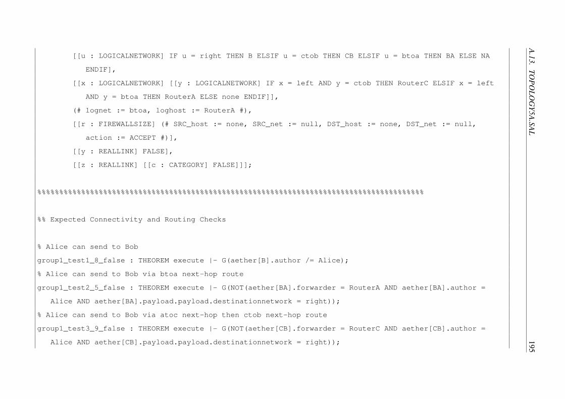
A.13.TO
POLO
GY5A.SAL
195
[[u : LOGICALNETWORK] IF u = right THEN B ELSIF u = ctob THEN CB ELSIF u = btoa THEN BA ELSE NA
ENDIF],
[[x : LOGICALNETWORK] [[y : LOGICALNETWORK] IF x = left AND y = ctob THEN RouterC ELSIF x = left
AND y = btoa THEN RouterA ELSE none ENDIF]],
(# lognet := btoa, loghost := RouterA #),
[[r : FIREWALLSIZE] (# SRC_host := none, SRC_net := null, DST_host := none, DST_net := null,
action := ACCEPT #)],
[[y : REALLINK] FALSE],
[[z : REALLINK] [[c : CATEGORY] FALSE]]];
%%%%%%%%%%%%%%%%%%%%%%%%%%%%%%%%%%%%%%%%%%%%%%%%%%%%%%%%%%%%%%%%%%%%%%%%%%%%%%%%%%%%%%%%
%% Expected Connectivity and Routing Checks
% Alice can send to Bob
group1_test1_8_false : THEOREM execute |- G(aether[B].author /= Alice);
% Alice can send to Bob via btoa next-hop route
group1_test2_5_false : THEOREM execute |- G(NOT(aether[BA].forwarder = RouterA AND aether[BA].author =
Alice AND aether[BA].payload.payload.destinationnetwork = right));
% Alice can send to Bob via atoc next-hop then ctob next-hop route
group1_test3_9_false : THEOREM execute |- G(NOT(aether[CB].forwarder = RouterC AND aether[CB].author =
Alice AND aether[CB].payload.payload.destinationnetwork = right));

196APPEN
DIX
A.M
OD
ELS
% Alice can send to Carlos via default route
group1_test4_8_false : THEOREM execute |- G(aether[C].author /= Alice);
% Bob can send to Alice
group2_test1_8_false : THEOREM execute |- G(aether[A].author /= Bob);
% Bob can send to Alice via ctob next-hop then atoc next-hop route
group2_test2_9_false : THEOREM execute |- G(NOT(aether[AC].forwarder = RouterC AND aether[AC].author = Bob
AND aether[AC].payload.payload.destinationnetwork = left));
% Bob can send to Alice via btoa next-hop route
group2_test3_5_false : THEOREM execute |- G(NOT(aether[BA].forwarder = RouterB AND aether[BA].author = Bob
AND aether[BA].payload.payload.destinationnetwork = left));
% Bob can send to Carlos via two default routes
group2_test4_12_false : THEOREM execute |- G(aether[C].author /= Bob);
% Carlos can only send to Alice via atoc next-hop route (due to RouterB source network check)
group3_test1_8_false : THEOREM execute |- G(aether[A].author /= Carlos);
% Carlos can only send to Bob via atoc next-hop then btoa next-hop route (due to RouterB source network
check)
group3_test2_12_false : THEOREM execute |- G(aether[B].author /= Carlos);
% RouterA can local route to atoc network

A.13.TO
POLO
GY5A.SAL
197
group4_test1_5_false : THEOREM execute |- G(NOT(aether[AC].author = Alice AND aether[AC].payload.payload.
destinationnetwork = atoc));
% RouterA can default route then RouterC can local route to ctob network
group4_test2_9_false : THEOREM execute |- G(NOT(aether[CB].author = Alice AND aether[CB].payload.payload.
destinationnetwork = ctob));
% RouterA can local route to btoa network
group4_test3_5_false : THEOREM execute |- G(NOT(aether[BA].author = Alice AND aether[BA].payload.payload.
destinationnetwork = btoa));
% RouterB can local route to btoa network
group4_test4_5_false : THEOREM execute |- G(NOT(aether[BA].author = Bob AND aether[BA].payload.payload.
destinationnetwork = btoa));
% RouterB can local route to ctob network
group4_test5_5_false : THEOREM execute |- G(NOT(aether[CB].author = Bob AND aether[CB].payload.payload.
destinationnetwork = ctob));
% RouterB can default route then RouterA can local route to atoc network
group4_test6_9_false : THEOREM execute |- G(NOT(aether[AC].author = Bob AND aether[AC].payload.payload.
destinationnetwork = atoc));
% RouterC can local route to atoc network
group4_test7_5_false : THEOREM execute |- G(NOT(aether[AC].author = Carlos AND aether[AC].payload.payload.
destinationnetwork = atoc));
% RouterC can local route to ctob network

198APPEN
DIX
A.M
OD
ELS
group4_test8_5_false : THEOREM execute |- G(NOT(aether[CB].author = Carlos AND aether[CB].payload.payload.
destinationnetwork = ctob));
%%%%%%%%%%%%%%%%%%%%%%%%%%%%%%%%%%%%%%%%%%%%%%%%%%%%%%%%%%%%%%%%%%%%%%%%%%%%%%%%%%%%%%%%
%% Source Network Check Proofs, incl. multi-layer header field validation
% All traffic that is successfully routed to Alice will have valid layer 2 and 3 headers
group5_test1_12_true : THEOREM execute |- G(aether[A].forwarder /= none =>
aether[A].forwarder = RouterA AND
((aether[A].author = Bob AND aether[A].payload.payload.sourcenetwork = right) OR (aether[A].author
= Carlos AND aether[A].payload.payload.sourcenetwork = top)) AND
aether[A].payload.source = RouterA AND
aether[A].payload.payload.destinationnetwork = left
);
% All traffic that is successfully routed to Bob will have valid layer 2 and 3 headers
group5_test2_12_true : THEOREM execute |- G(aether[B].forwarder /= none =>
aether[B].forwarder = RouterB AND
((aether[B].author = Alice AND aether[B].payload.payload.sourcenetwork = left) OR (aether[B].
author = Carlos AND aether[B].payload.payload.sourcenetwork = top)) AND
aether[B].payload.source = RouterB AND

A.13.TO
POLO
GY5A.SAL
199
aether[B].payload.payload.destinationnetwork = right
);
% All traffic that is successfully routed to Carlos will have valid layer 2 and 3 headers
group5_test3_12_true : THEOREM execute |- G(aether[C].forwarder /= none =>
aether[C].forwarder = RouterC AND
((aether[C].author = Bob AND aether[C].payload.payload.sourcenetwork = right) OR (aether[C].author
= Alice AND aether[C].payload.payload.sourcenetwork = left)) AND
aether[C].payload.source = RouterC AND
aether[C].payload.payload.destinationnetwork = top
);
%%%%%%%%%%%%%%%%%%%%%%%%%%%%%%%%%%%%%%%%%%%%%%%%%%%%%%%%%%%%%%%%%%%%%%%%%%%%%%%%%%%%%%%%
%% Impossible routes
% RouterA should never route traffic for the top network via the btoa network
group6_test1_12_true : THEOREM execute |- G(aether[BA].payload.payload.destinationnetwork = top => aether[
BA].author = Bob);
% RouterB should never route traffic for the top network via the ctob network
group6_test2_12_true : THEOREM execute |- G(aether[CB].payload.payload.destinationnetwork /= top);

200APPEN
DIX
A.M
OD
ELS
% Carlos cannot have his traffic successfully routed to the btoa network as destination because RouterC
has no route to it
group6_test3_12_true : THEOREM execute |- G(NOT(aether[BA].author = Carlos AND aether[BA].payload.payload.
destinationnetwork = btoa));
% Carlos cannot have his traffic successfully routed to Alice via the btoa network because although
RouterC has the route, RouterB’s source network check will discard it
group6_test4_12_true : THEOREM execute |- G(NOT(aether[BA].author = Carlos AND aether[BA].payload.payload.
destinationnetwork = left));
%%%%%%%%%%%%%%%%%%%%%%%%%%%%%%%%%%%%%%%%%%%%%%%%%%%%%%%%%%%%%%%%%%%%%%%%%%%%%%%%%%%%%%%%
%% Other Erroneous traffic
% Layer 2 broadcast traffic is never routed
group7_test1_12_true : THEOREM execute |- G(FORALL (a : REALLINK) : aether[a].payload.destination =
broadcast => aether[a].forwarder = topology!none);
% Layer 3 broadcast traffic is never routed
group7_test2_12_true : THEOREM execute |- G(FORALL (a : REALLINK) : aether[a].payload.payload.
destinationhost = broadcast => aether[a].forwarder = topology!none);
%%%%%%%%%%%%%%%%%%%%%%%%%%%%%%%%%%%%%%%%%%%%%%%%%%%%%%%%%%%%%%%%%%%%%%%%%%%%%%%%%%%%%%%%

A.14.TO
POLO
GY5B.SAL
201
%% ARP behavioural checks
% Routers never add their own address to ARP table
group8_test1_12_true : THEOREM execute |- G(FORALL (a : HOST) : resolv.1.1[a].phyaddr /= RouterA AND
resolv.1.2[a].phyaddr /= RouterC AND resolv.2[a].phyaddr /= RouterB);
END
A.14 topology5b.sal
topology : CONTEXT =
BEGIN
NODE : TYPE = {none, Alice, Bob, Carlos, RouterA, RouterB, RouterC, broadcast};
CLIENT : TYPE = {u : topology!NODE | u /= topology!none AND u /= topology!broadcast};
LINK : TYPE = {NA, A, B, C, AC, CB, BA};
LOGICALNETWORKADDR : TYPE = {null, left, top, right, atoc, ctob, btoa};
FIREWALLSIZE : TYPE = [1..1];
CATEGORY : TYPE = {c0};
IMPORTING network;

202APPEN
DIX
A.M
OD
ELS
execute : MODULE =
establishconnections
[]host!stateless[Alice, A, TRUE, left, 1]
[]host!stateless[Carlos, C, TRUE, top, 1]
[]host!stateless[Bob, B, TRUE, right, 1]
[]router!router[
RouterA,
FALSE,
[[i : REALLINK] i = A OR i = AC OR i = BA],
[[u : LOGICALNETWORK] IF u = left THEN A ELSIF u = atoc THEN AC ELSIF u = btoa THEN BA ELSE NA
ENDIF],
[[x : LOGICALNETWORK] [[y : LOGICALNETWORK] IF x = right AND y = atoc THEN RouterC ELSIF x = right
AND y = btoa THEN RouterB ELSE none ENDIF]],
(# lognet := atoc, loghost := RouterC #),
[[r : FIREWALLSIZE] (# SRC_host := none, SRC_net := null, DST_host := none, DST_net := null,
action := ACCEPT #)],
[[y : REALLINK] FALSE],
[[z : REALLINK] [[c : CATEGORY] FALSE]]]

A.14.TO
POLO
GY5B.SAL
203
[]router!router[
RouterC,
FALSE,
[[i : REALLINK] i = C OR i = AC OR i = CB],
[[u : LOGICALNETWORK] IF u = top THEN C ELSIF u = atoc THEN AC ELSIF u = ctob THEN CB ELSE NA
ENDIF],
[[x : LOGICALNETWORK] [[y : LOGICALNETWORK] IF x = left AND y = atoc THEN RouterA ELSIF x = left
AND y = ctob THEN RouterB ELSIF x = right AND y = atoc THEN RouterA ELSIF x = right AND y =
ctob THEN RouterB ELSE none ENDIF]],
(# lognet := null, loghost := none #),
[[r : FIREWALLSIZE] (# SRC_host := none, SRC_net := null, DST_host := none, DST_net := null,
action := ACCEPT #)],
[[y : REALLINK] FALSE],
[[z : REALLINK] [[c : CATEGORY] FALSE]]]
[]router!router[
RouterB,
TRUE,
[[i : REALLINK] i = B OR i = CB OR i = BA],
[[u : LOGICALNETWORK] IF u = right THEN B ELSIF u = ctob THEN CB ELSIF u = btoa THEN BA ELSE NA
ENDIF],

204APPEN
DIX
A.M
OD
ELS
[[x : LOGICALNETWORK] [[y : LOGICALNETWORK] IF x = left AND y = ctob THEN RouterC ELSIF x = left
AND y = btoa THEN RouterA ELSE none ENDIF]],
(# lognet := btoa, loghost := RouterA #),
[[r : FIREWALLSIZE] (# SRC_host := none, SRC_net := null, DST_host := none, DST_net := null,
action := ACCEPT #)],
[[y : REALLINK] FALSE],
[[z : REALLINK] [[c : CATEGORY] FALSE]]];
%%%%%%%%%%%%%%%%%%%%%%%%%%%%%%%%%%%%%%%%%%%%%%%%%%%%%%%%%%%%%%%%%%%%%%%%%%%%%%%%%%%%%%%%
%% Expected Connectivity and Routing Checks
% Alice can send to Bob
group1_test1_8_false : THEOREM execute |- G(aether[B].author /= Alice);
% Alice can send to Bob via btoa next-hop route
group1_test2_5_false : THEOREM execute |- G(NOT(aether[BA].forwarder = RouterA AND aether[BA].author =
Alice AND aether[BA].payload.payload.destinationnetwork = right));
% Alice can send to Bob via atoc next-hop then ctob next-hop route
group1_test3_9_false : THEOREM execute |- G(NOT(aether[CB].forwarder = RouterC AND aether[CB].author =
Alice AND aether[CB].payload.payload.destinationnetwork = right));
% Alice can send to Carlos via default route
group1_test4_8_false : THEOREM execute |- G(aether[C].author /= Alice);

A.14.TO
POLO
GY5B.SAL
205
% Bob can send to Alice
group2_test1_8_false : THEOREM execute |- G(aether[A].author /= Bob);
% Bob can send to Alice via ctob next-hop then atoc next-hop route
group2_test2_9_false : THEOREM execute |- G(NOT(aether[AC].forwarder = RouterC AND aether[AC].author = Bob
AND aether[AC].payload.payload.destinationnetwork = left));
% Bob can send to Alice via btoa next-hop route
group2_test3_5_false : THEOREM execute |- G(NOT(aether[BA].forwarder = RouterB AND aether[BA].author = Bob
AND aether[BA].payload.payload.destinationnetwork = left));
% Bob can send to Carlos via two default routes
group2_test4_12_false : THEOREM execute |- G(aether[C].author /= Bob);
% Carlos can send to Alice
group3_test1_8_false : THEOREM execute |- G(aether[A].author /= Carlos);
% Carlos can send to Alice via atoc next-hop route
group3_test2_5_false : THEOREM execute |- G(NOT(aether[AC].forwarder = RouterC AND aether[AC].author =
Carlos AND aether[AC].payload.payload.destinationnetwork = left));
% Carlos can send to Alice via ctob next-hop then btoa next-hop route when RouterB’s source network check
is disabled
group3_test3_9_false : THEOREM execute |- G(NOT(aether[BA].forwarder = RouterB AND aether[BA].author =
Carlos AND aether[BA].payload.payload.destinationnetwork = left));
% Carlos can send to Bob via ctob next-hop route when RouterB’s source network check is disabled

206APPEN
DIX
A.M
OD
ELS
group3_test4_8_false : THEOREM execute |- G(aether[B].author /= Carlos);
% Carlos can send to Bob via atoc next-hop then btoa next-hop route
group3_test5_9_false : THEOREM execute |- G(NOT(aether[BA].forwarder = RouterA AND aether[BA].author =
Carlos AND aether[BA].payload.payload.destinationnetwork = right));
% RouterA can local route to atoc network
group4_test1_5_false : THEOREM execute |- G(NOT(aether[AC].author = Alice AND aether[AC].payload.payload.
destinationnetwork = atoc));
% RouterA can default route then RouterC can local route to ctob network
group4_test2_9_false : THEOREM execute |- G(NOT(aether[CB].author = Alice AND aether[CB].payload.payload.
destinationnetwork = ctob));
% RouterA can local route to btoa network
group4_test3_5_false : THEOREM execute |- G(NOT(aether[BA].author = Alice AND aether[BA].payload.payload.
destinationnetwork = btoa));
% RouterB can local route to btoa network
group4_test4_5_false : THEOREM execute |- G(NOT(aether[BA].author = Bob AND aether[BA].payload.payload.
destinationnetwork = btoa));
% RouterB can local route to ctob network
group4_test5_5_false : THEOREM execute |- G(NOT(aether[CB].author = Bob AND aether[CB].payload.payload.
destinationnetwork = ctob));
% RouterB can default route then RouterA can local route to atoc network

A.14.TO
POLO
GY5B.SAL
207
group4_test6_9_false : THEOREM execute |- G(NOT(aether[AC].author = Bob AND aether[AC].payload.payload.
destinationnetwork = atoc));
% RouterC can local route to atoc network
group4_test7_5_false : THEOREM execute |- G(NOT(aether[AC].author = Carlos AND aether[AC].payload.payload.
destinationnetwork = atoc));
% RouterC can local route to ctob network
group4_test8_5_false : THEOREM execute |- G(NOT(aether[CB].author = Carlos AND aether[CB].payload.payload.
destinationnetwork = ctob));
%%%%%%%%%%%%%%%%%%%%%%%%%%%%%%%%%%%%%%%%%%%%%%%%%%%%%%%%%%%%%%%%%%%%%%%%%%%%%%%%%%%%%%%%
%% Source Network Check Proofs, incl. multi-layer header field validation
% All traffic that is successfully routed to Alice will have valid layer 2 and 3 headers
group5_test1_12_false : THEOREM execute |- G(aether[A].forwarder /= none =>
aether[A].forwarder = RouterA AND
((aether[A].author = Bob AND aether[A].payload.payload.sourcenetwork = right) OR (aether[A].author
= Carlos AND aether[A].payload.payload.sourcenetwork = top)) AND
aether[A].payload.source = RouterA AND
aether[A].payload.payload.destinationnetwork = left
);

208APPEN
DIX
A.M
OD
ELS
% All traffic that is successfully routed to Bob will have valid layer 2 and 3 headers
group5_test2_12_true : THEOREM execute |- G(aether[B].forwarder /= none =>
aether[B].forwarder = RouterB AND
((aether[B].author = Alice AND aether[B].payload.payload.sourcenetwork = left) OR (aether[B].
author = Carlos AND aether[B].payload.payload.sourcenetwork = top)) AND
aether[B].payload.source = RouterB AND
aether[B].payload.payload.destinationnetwork = right
);
% All traffic that is successfully routed to Carlos will have valid layer 2 and 3 headers
group5_test3_12_true : THEOREM execute |- G(aether[C].forwarder /= none =>
aether[C].forwarder = RouterC AND
((aether[C].author = Bob AND aether[C].payload.payload.sourcenetwork = right) OR (aether[C].author
= Alice AND aether[C].payload.payload.sourcenetwork = left)) AND
aether[C].payload.source = RouterC AND
aether[C].payload.payload.destinationnetwork = top
);
% Although RouterB’s disabled source network checking permits the routing of traffic with spoofed source
network addresses, Routers A and Bs’ source network check will still drop erroneous traffic for routes
they are aware of

A.14.TO
POLO
GY5B.SAL
209
group5_test4_12_true : THEOREM execute |- G(aether[A].forwarder /= none => aether[A].payload.payload.
sourcenetwork /= left AND aether[A].payload.payload.sourcenetwork /= atoc);
group5_test5_12_true : THEOREM execute |- G(aether[C].forwarder /= none => aether[C].payload.payload.
sourcenetwork /= top AND aether[C].payload.payload.sourcenetwork /= atoc);
%%%%%%%%%%%%%%%%%%%%%%%%%%%%%%%%%%%%%%%%%%%%%%%%%%%%%%%%%%%%%%%%%%%%%%%%%%%%%%%%%%%%%%%%
%% Impossible routes
% RouterA should never route traffic for the top network via the btoa network
group6_test1_12_true : THEOREM execute |- G(aether[BA].payload.payload.destinationnetwork = top => aether[
BA].author = Bob);
% RouterB should never route traffic for the top network via the ctob network
group6_test2_12_true : THEOREM execute |- G(aether[CB].payload.payload.destinationnetwork /= top);
% Carlos cannot have his traffic successfully routed to the btoa network as destination because RouterC
has no route to it
group6_test3_12_true : THEOREM execute |- G(NOT(aether[BA].author = Carlos AND aether[BA].payload.payload.
destinationnetwork = btoa));
%%%%%%%%%%%%%%%%%%%%%%%%%%%%%%%%%%%%%%%%%%%%%%%%%%%%%%%%%%%%%%%%%%%%%%%%%%%%%%%%%%%%%%%%
%% Other Erroneous traffic

210APPEN
DIX
A.M
OD
ELS
% Layer 2 broadcast traffic is never routed
group7_test1_12_true : THEOREM execute |- G(FORALL (a : REALLINK) : aether[a].payload.destination =
broadcast => aether[a].forwarder = topology!none);
% Layer 3 broadcast traffic is never routed
group7_test2_12_true : THEOREM execute |- G(FORALL (a : REALLINK) : aether[a].payload.payload.
destinationhost = broadcast => aether[a].forwarder = topology!none);
%%%%%%%%%%%%%%%%%%%%%%%%%%%%%%%%%%%%%%%%%%%%%%%%%%%%%%%%%%%%%%%%%%%%%%%%%%%%%%%%%%%%%%%%
%% ARP behavioural checks
% Routers never add their own address to ARP table
group8_test1_12_true : THEOREM execute |- G(FORALL (a : HOST) : resolv.1.1[a].phyaddr /= RouterA AND
resolv.1.2[a].phyaddr /= RouterC AND resolv.2[a].phyaddr /= RouterB);
END
A.15 topology5c.sal
topology : CONTEXT =

A.15.TO
POLO
GY5C
.SAL211
BEGIN
NODE : TYPE = {none, Alice, Bob, Carlos, RouterA, RouterB, RouterC, broadcast};
CLIENT : TYPE = {u : topology!NODE | u /= topology!none AND u /= topology!broadcast};
LINK : TYPE = {NA, A, B, C, AC, CB, BA};
LOGICALNETWORKADDR : TYPE = {null, left, top, right, atoc, ctob, btoa};
FIREWALLSIZE : TYPE = [1..5];
CATEGORY : TYPE = {c0};
IMPORTING network;
execute : MODULE =
establishconnections
[]host!stateless[Alice, A, TRUE, left, 1]
[]host!stateless[Carlos, C, TRUE, top, 1]
[]host!stateless[Bob, B, TRUE, right, 1]
[]router!router[
RouterA,
FALSE,
[[i : REALLINK] i = A OR i = AC OR i = BA],

212APPEN
DIX
A.M
OD
ELS
[[u : LOGICALNETWORK] IF u = left THEN A ELSIF u = atoc THEN AC ELSIF u = btoa THEN BA ELSE NA
ENDIF],
[[x : LOGICALNETWORK] [[y : LOGICALNETWORK] IF x = right AND y = atoc THEN RouterC ELSIF x = right
AND y = btoa THEN RouterB ELSE none ENDIF]],
(# lognet := atoc, loghost := RouterC #),
[[r : FIREWALLSIZE] IF r = 1 THEN (# SRC_host := none, SRC_net := null, DST_host := none, DST_net
:= atoc, action := DISCARD #) ELSIF r = 2 THEN (# SRC_host := none, SRC_net := null, DST_host
:= none, DST_net := btoa, action := DISCARD #) ELSIF r = 3 THEN (# SRC_host := Alice, SRC_net
:= left, DST_host := none, DST_net := null, action := ACCEPT #) ELSIF r = 4 THEN (# SRC_host :=
none, SRC_net := left, DST_host := none, DST_net := null, action := DISCARD #) ELSE (#
SRC_host := none, SRC_net := null, DST_host := none, DST_net := null, action := ACCEPT #) ENDIF
],
[[y : REALLINK] FALSE],
[[z : REALLINK] [[c : CATEGORY] FALSE]]]
[]router!router[
RouterC,
FALSE,
[[i : REALLINK] i = C OR i = AC OR i = CB],
[[u : LOGICALNETWORK] IF u = top THEN C ELSIF u = atoc THEN AC ELSIF u = ctob THEN CB ELSE NA
ENDIF],

A.15.TO
POLO
GY5C
.SAL213
[[x : LOGICALNETWORK] [[y : LOGICALNETWORK] IF x = left AND y = atoc THEN RouterA ELSIF x = left
AND y = ctob THEN RouterB ELSIF x = right AND y = atoc THEN RouterA ELSIF x = right AND y =
ctob THEN RouterB ELSE none ENDIF]],
(# lognet := null, loghost := none #),
[[r : FIREWALLSIZE] IF r = 1 THEN (# SRC_host := none, SRC_net := null, DST_host := none, DST_net
:= ctob, action := DISCARD #) ELSIF r = 2 THEN (# SRC_host := none, SRC_net := null, DST_host
:= none, DST_net := atoc, action := DISCARD #) ELSIF r = 3 THEN (# SRC_host := Carlos, SRC_net
:= top, DST_host := none, DST_net := null, action := ACCEPT #) ELSIF r = 4 THEN (# SRC_host :=
none, SRC_net := top, DST_host := none, DST_net := null, action := DISCARD #) ELSE (# SRC_host
:= none, SRC_net := null, DST_host := none, DST_net := null, action := ACCEPT #) ENDIF],
[[y : REALLINK] FALSE],
[[z : REALLINK] [[c : CATEGORY] FALSE]]]
[]router!router[
RouterB,
FALSE,
[[i : REALLINK] i = B OR i = CB OR i = BA],
[[u : LOGICALNETWORK] IF u = right THEN B ELSIF u = ctob THEN CB ELSIF u = btoa THEN BA ELSE NA
ENDIF],
[[x : LOGICALNETWORK] [[y : LOGICALNETWORK] IF x = left AND y = ctob THEN RouterC ELSIF x = left
AND y = btoa THEN RouterA ELSE none ENDIF]],
(# lognet := btoa, loghost := RouterA #),

214APPEN
DIX
A.M
OD
ELS
[[r : FIREWALLSIZE] IF r = 1 THEN (# SRC_host := none, SRC_net := null, DST_host := none, DST_net
:= btoa, action := DISCARD #) ELSIF r = 2 THEN (# SRC_host := none, SRC_net := null, DST_host
:= none, DST_net := ctob, action := DISCARD #) ELSIF r = 3 THEN (# SRC_host := Bob, SRC_net :=
right, DST_host := none, DST_net := null, action := ACCEPT #) ELSIF r = 4 THEN (# SRC_host :=
none, SRC_net := right, DST_host := none, DST_net := null, action := DISCARD #) ELSE (#
SRC_host := none, SRC_net := null, DST_host := none, DST_net := null, action := ACCEPT #) ENDIF
],
[[y : REALLINK] FALSE],
[[z : REALLINK] [[c : CATEGORY] FALSE]]];
%%%%%%%%%%%%%%%%%%%%%%%%%%%%%%%%%%%%%%%%%%%%%%%%%%%%%%%%%%%%%%%%%%%%%%%%%%%%%%%%%%%%%%%%
%% Expected Connectivity and Routing Checks
% Alice can send to Bob
group1_test1_8_false : THEOREM execute |- G(aether[B].author /= Alice);
% Alice can send to Bob via btoa next-hop route
group1_test2_5_false : THEOREM execute |- G(NOT(aether[BA].forwarder = RouterA AND aether[BA].author =
Alice AND aether[BA].payload.payload.destinationnetwork = right));
% Alice can send to Bob via atoc next-hop then ctob next-hop route
group1_test3_9_false : THEOREM execute |- G(NOT(aether[CB].forwarder = RouterC AND aether[CB].author =
Alice AND aether[CB].payload.payload.destinationnetwork = right));
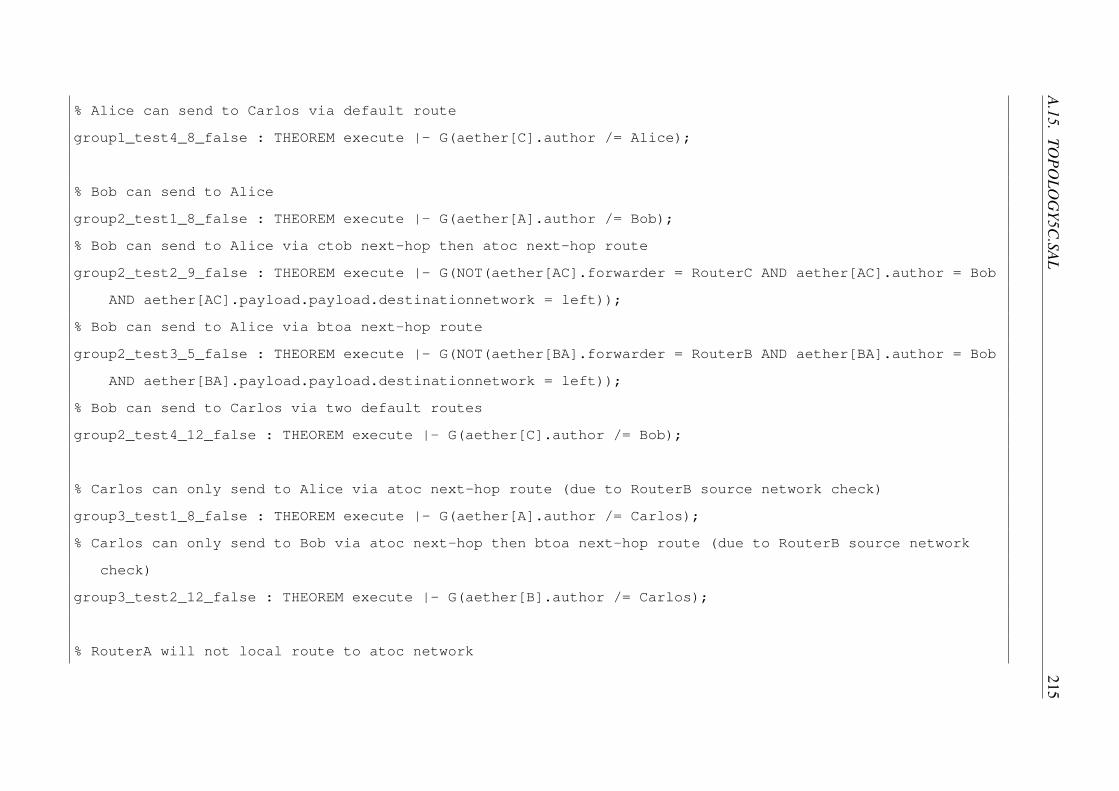
A.15.TO
POLO
GY5C
.SAL215
% Alice can send to Carlos via default route
group1_test4_8_false : THEOREM execute |- G(aether[C].author /= Alice);
% Bob can send to Alice
group2_test1_8_false : THEOREM execute |- G(aether[A].author /= Bob);
% Bob can send to Alice via ctob next-hop then atoc next-hop route
group2_test2_9_false : THEOREM execute |- G(NOT(aether[AC].forwarder = RouterC AND aether[AC].author = Bob
AND aether[AC].payload.payload.destinationnetwork = left));
% Bob can send to Alice via btoa next-hop route
group2_test3_5_false : THEOREM execute |- G(NOT(aether[BA].forwarder = RouterB AND aether[BA].author = Bob
AND aether[BA].payload.payload.destinationnetwork = left));
% Bob can send to Carlos via two default routes
group2_test4_12_false : THEOREM execute |- G(aether[C].author /= Bob);
% Carlos can only send to Alice via atoc next-hop route (due to RouterB source network check)
group3_test1_8_false : THEOREM execute |- G(aether[A].author /= Carlos);
% Carlos can only send to Bob via atoc next-hop then btoa next-hop route (due to RouterB source network
check)
group3_test2_12_false : THEOREM execute |- G(aether[B].author /= Carlos);
% RouterA will not local route to atoc network

216APPEN
DIX
A.M
OD
ELS
group4_test1_5_true : THEOREM execute |- G(NOT(aether[AC].author = Alice AND aether[AC].payload.payload.
destinationnetwork = atoc));
% RouterA will not default route traffic destined for the ctob network
group4_test2_9_true : THEOREM execute |- G(NOT(aether[CB].author = Alice AND aether[CB].payload.payload.
destinationnetwork = ctob));
% RouterA will not local route to btoa network
group4_test3_5_true : THEOREM execute |- G(NOT(aether[BA].author = Alice AND aether[BA].payload.payload.
destinationnetwork = btoa));
% RouterB will not local route to btoa network
group4_test4_5_true : THEOREM execute |- G(NOT(aether[BA].author = Bob AND aether[BA].payload.payload.
destinationnetwork = btoa));
% RouterB will not local route to ctob network
group4_test5_5_true : THEOREM execute |- G(NOT(aether[CB].author = Bob AND aether[CB].payload.payload.
destinationnetwork = ctob));
% RouterB will not default route traffic destined for the atoc network
group4_test6_9_true : THEOREM execute |- G(NOT(aether[AC].author = Bob AND aether[AC].payload.payload.
destinationnetwork = atoc));
% RouterC will not local route to atoc network
group4_test7_5_true : THEOREM execute |- G(NOT(aether[AC].author = Carlos AND aether[AC].payload.payload.
destinationnetwork = atoc));
% RouterC will not local route to ctob network

A.15.TO
POLO
GY5C
.SAL217
group4_test8_5_true : THEOREM execute |- G(NOT(aether[CB].author = Carlos AND aether[CB].payload.payload.
destinationnetwork = ctob));
%%%%%%%%%%%%%%%%%%%%%%%%%%%%%%%%%%%%%%%%%%%%%%%%%%%%%%%%%%%%%%%%%%%%%%%%%%%%%%%%%%%%%%%%
%% Source Network Check Proofs, incl. multi-layer header field validation
% All traffic that is successfully routed to Alice will have valid layer 2 and 3 headers
group5_test1_12_true : THEOREM execute |- G(aether[A].forwarder /= none =>
aether[A].forwarder = RouterA AND
((aether[A].author = Bob AND aether[A].payload.payload.sourcenetwork = right) OR (aether[A].author
= Carlos AND aether[A].payload.payload.sourcenetwork = top)) AND
aether[A].payload.source = RouterA AND
aether[A].payload.payload.destinationnetwork = left
);
% All traffic that is successfully routed to Bob will have valid layer 2 and 3 headers
group5_test2_12_true : THEOREM execute |- G(aether[B].forwarder /= none =>
aether[B].forwarder = RouterB AND
((aether[B].author = Alice AND aether[B].payload.payload.sourcenetwork = left) OR (aether[B].
author = Carlos AND aether[B].payload.payload.sourcenetwork = top)) AND
aether[B].payload.source = RouterB AND

218APPEN
DIX
A.M
OD
ELS
aether[B].payload.payload.destinationnetwork = right
);
% All traffic that is successfully routed to Carlos will have valid layer 2 and 3 headers
group5_test3_12_true : THEOREM execute |- G(aether[C].forwarder /= none =>
aether[C].forwarder = RouterC AND
((aether[C].author = Bob AND aether[C].payload.payload.sourcenetwork = right) OR (aether[C].author
= Alice AND aether[C].payload.payload.sourcenetwork = left)) AND
aether[C].payload.source = RouterC AND
aether[C].payload.payload.destinationnetwork = top
);
%%%%%%%%%%%%%%%%%%%%%%%%%%%%%%%%%%%%%%%%%%%%%%%%%%%%%%%%%%%%%%%%%%%%%%%%%%%%%%%%%%%%%%%%
%% Impossible routes
% RouterA should never route traffic for the top network via the btoa network
group6_test1_12_true : THEOREM execute |- G(aether[BA].payload.payload.destinationnetwork = top => aether[
BA].author = Bob);
% RouterB should never route traffic for the top network via the ctob network
group6_test2_12_true : THEOREM execute |- G(aether[CB].payload.payload.destinationnetwork /= top);
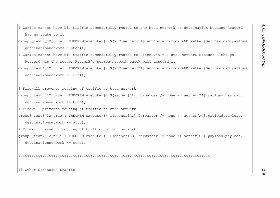
A.15.TO
POLO
GY5C
.SAL219
% Carlos cannot have his traffic successfully routed to the btoa network as destination because RouterC
has no route to it
group6_test3_12_true : THEOREM execute |- G(NOT(aether[BA].author = Carlos AND aether[BA].payload.payload.
destinationnetwork = btoa));
% Carlos cannot have his traffic successfully routed to Alice via the btoa network because although
RouterC has the route, RouterB’s source network check will discard it
group6_test4_12_true : THEOREM execute |- G(NOT(aether[BA].author = Carlos AND aether[BA].payload.payload.
destinationnetwork = left));
% Firewall prevents routing of traffic to btoa network
group6_test5_12_true : THEOREM execute |- G(aether[BA].forwarder /= none => aether[BA].payload.payload.
destinationnetwork /= btoa);
% Firewall prevents routing of traffic to ctoa network
group6_test6_12_true : THEOREM execute |- G(aether[AC].forwarder /= none => aether[AC].payload.payload.
destinationnetwork /= atoc);
% Firewall prevents routing of traffic to ctob network
group6_test7_12_true : THEOREM execute |- G(aether[CB].forwarder /= none => aether[CB].payload.payload.
destinationnetwork /= ctob);
%%%%%%%%%%%%%%%%%%%%%%%%%%%%%%%%%%%%%%%%%%%%%%%%%%%%%%%%%%%%%%%%%%%%%%%%%%%%%%%%%%%%%%%%
%% Other Erroneous traffic

220APPEN
DIX
A.M
OD
ELS
% Layer 2 broadcast traffic is never routed
group7_test1_12_true : THEOREM execute |- G(FORALL (a : REALLINK) : aether[a].payload.destination =
broadcast => aether[a].forwarder = topology!none);
% Layer 3 broadcast traffic is never routed
group7_test2_12_true : THEOREM execute |- G(FORALL (a : REALLINK) : aether[a].payload.payload.
destinationhost = broadcast => aether[a].forwarder = topology!none);
%%%%%%%%%%%%%%%%%%%%%%%%%%%%%%%%%%%%%%%%%%%%%%%%%%%%%%%%%%%%%%%%%%%%%%%%%%%%%%%%%%%%%%%%
%% ARP behavioural checks
% Routers never add their own address to ARP table
group8_test1_12_true : THEOREM execute |- G(FORALL (a : HOST) : resolv.1.1[a].phyaddr /= RouterA AND
resolv.1.2[a].phyaddr /= RouterC AND resolv.2[a].phyaddr /= RouterB);
%%%%%%%%%%%%%%%%%%%%%%%%%%%%%%%%%%%%%%%%%%%%%%%%%%%%%%%%%%%%%%%%%%%%%%%%%%%%%%%%%%%%%%%%
%% Additional firewall check
% All routed traffic cannot have a spoofed source host address

A.16.TO
POLO
GY6.SAL
221
group9_test1_12_true : THEOREM execute |- G(FORALL (a : REALLINK) : aether[a].forwarder /= none => aether[
a].payload.payload.sourcehost = aether[a].author);
END
A.16 topology6.sal
topology : CONTEXT =
BEGIN
NODE : TYPE = {none, A1, A2, A3, AS, SGA, SGB, BS, B1, B2, B3, broadcast};
CLIENT : TYPE = {u : topology!NODE | u /= topology!none AND u /= topology!broadcast};
LINK : TYPE = {NA, A1C, A2C, A3C, ASR, PPP, BSR, B1C, B2C, B3C};
LOGICALNETWORKADDR : TYPE = {null, anet, internet, bnet};
FIREWALLSIZE : TYPE = [1..8];
CATEGORY : TYPE = {c0};
IMPORTING network;
execute : MODULE =
establishconnections
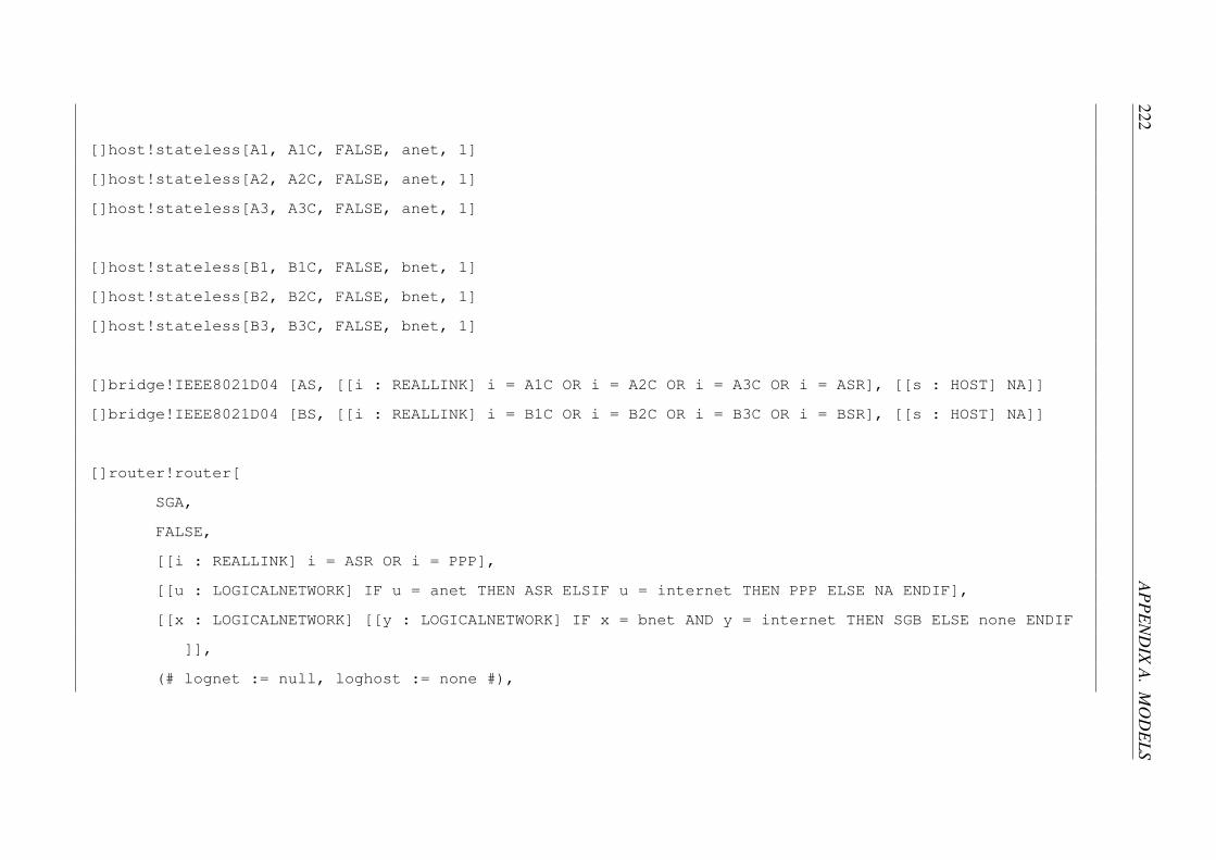
222APPEN
DIX
A.M
OD
ELS
[]host!stateless[A1, A1C, FALSE, anet, 1]
[]host!stateless[A2, A2C, FALSE, anet, 1]
[]host!stateless[A3, A3C, FALSE, anet, 1]
[]host!stateless[B1, B1C, FALSE, bnet, 1]
[]host!stateless[B2, B2C, FALSE, bnet, 1]
[]host!stateless[B3, B3C, FALSE, bnet, 1]
[]bridge!IEEE8021D04 [AS, [[i : REALLINK] i = A1C OR i = A2C OR i = A3C OR i = ASR], [[s : HOST] NA]]
[]bridge!IEEE8021D04 [BS, [[i : REALLINK] i = B1C OR i = B2C OR i = B3C OR i = BSR], [[s : HOST] NA]]
[]router!router[
SGA,
FALSE,
[[i : REALLINK] i = ASR OR i = PPP],
[[u : LOGICALNETWORK] IF u = anet THEN ASR ELSIF u = internet THEN PPP ELSE NA ENDIF],
[[x : LOGICALNETWORK] [[y : LOGICALNETWORK] IF x = bnet AND y = internet THEN SGB ELSE none ENDIF
]],
(# lognet := null, loghost := none #),

A.16.TO
POLO
GY6.SAL
223
[[r : FIREWALLSIZE] IF r = 1 THEN (# SRC_host := A1, SRC_net := anet, DST_host := B1, DST_net :=
bnet, action := ACCEPT #) ELSIF r = 2 THEN (# SRC_host := A2, SRC_net := anet, DST_host := B2,
DST_net := bnet, action := ACCEPT #) ELSIF r = 3 THEN (# SRC_host := A3, SRC_net := anet,
DST_host := B3, DST_net := bnet, action := ACCEPT #) ELSIF r = 4 THEN (# SRC_host := A2,
SRC_net := anet, DST_host := B3, DST_net := bnet, action := DISCARD #) ELSIF r = 5 THEN (#
SRC_host := none, SRC_net := anet, DST_host := B2, DST_net := bnet, action := DISCARD #) ELSIF
r = 6 THEN (# SRC_host := none, SRC_net := anet, DST_host := none, DST_net := bnet, action :=
ACCEPT #) ELSIF r = 7 THEN (# SRC_host := A2, SRC_net := anet, DST_host := B1, DST_net := bnet,
action := ACCEPT #) ELSIF r = 8 THEN (# SRC_host := A1, SRC_net := anet, DST_host := none,
DST_net := bnet, action := DISCARD #) ELSE (# SRC_host := none, SRC_net := null, DST_host :=
none, DST_net := null, action := DISCARD #) ENDIF],
[[y : REALLINK] FALSE],
[[z : REALLINK] [[c : CATEGORY] FALSE]]]
[]router!router[
SGB,
FALSE,
[[i : REALLINK] i = BSR OR i = PPP],
[[u : LOGICALNETWORK] IF u = bnet THEN BSR ELSIF u = internet THEN PPP ELSE NA ENDIF],
[[x : LOGICALNETWORK] [[y : LOGICALNETWORK] IF x = anet AND y = internet THEN SGA ELSE none ENDIF
]],
(# lognet := null, loghost := none #),

224APPEN
DIX
A.M
OD
ELS
[[r : FIREWALLSIZE] IF r = 1 THEN (# SRC_host := A1, SRC_net := anet, DST_host := B1, DST_net :=
bnet, action := ACCEPT #) ELSIF r = 2 THEN (# SRC_host := A2, SRC_net := anet, DST_host := B2,
DST_net := bnet, action := ACCEPT #) ELSIF r = 3 THEN (# SRC_host := A3, SRC_net := anet,
DST_host := B3, DST_net := bnet, action := ACCEPT #) ELSIF r = 4 THEN (# SRC_host := A2,
SRC_net := anet, DST_host := B3, DST_net := bnet, action := ACCEPT #) ELSIF r = 5 THEN (#
SRC_host := A3, SRC_net := anet, DST_host := B2, DST_net := bnet, action := ACCEPT #) ELSIF r =
6 THEN (# SRC_host := A1, SRC_net := anet, DST_host := B3, DST_net := bnet, action := DISCARD
#) ELSIF r = 7 THEN (# SRC_host := none, SRC_net := anet, DST_host := B1, DST_net := bnet,
action := ACCEPT #) ELSIF r = 8 THEN (# SRC_host := A2, SRC_net := anet, DST_host := none,
DST_net := bnet, action := DISCARD #) ELSE (# SRC_host := none, SRC_net := null, DST_host :=
none, DST_net := null, action := DISCARD #) ENDIF],
[[y : REALLINK] FALSE],
[[z : REALLINK] [[c : CATEGORY] FALSE]]];
%% A1
% Common accept rule 1 on each firewall
group1_test1_12_false : THEOREM execute |- G(aether[B1C].author /= A1);
% SGA rule 5 discard
group1_test2_12_true : THEOREM execute |- G(aether[B2C].author /= A1);

A.16.TO
POLO
GY6.SAL
225
% Inter-policy partial spuriousness between rule 6 on each firewall
group1_test3_12_true : THEOREM execute |- G(aether[B3C].author /= A1);
%% A2
% Rule 6 and Rule 7 accept rules on SGA and SGB, respectively
group2_test1_12_false : THEOREM execute |- G(aether[B1C].author /= A2);
% Common accept rule 2 on each firewall
group2_test2_12_false : THEOREM execute |- G(aether[B2C].author /= A2);
% Inter-policy complete shadowing between rule 4 on each firewall
group2_test3_13_true : THEOREM execute |- G(aether[B3C].author /= A2);
%% A3
% Rule 6 and Rule 7 accept rules on SGA and SGB, respectively
group3_test1_12_false : THEOREM execute |- G(aether[B1C].author /= A3);
% Inter-policy partial shadowing between rule 5 on each firewall
group3_test2_12_true : THEOREM execute |- G(aether[B2C].author /= A3);

226APPEN
DIX
A.M
OD
ELS
% Common accept rule 3 on each firewall
group3_test3_12_false : THEOREM execute |- G(aether[B3C].author /= A3);
END
A.17 topology7.sal
topology : CONTEXT =
BEGIN
NODE : TYPE = {none, alice, bob, carlos, dave, router, broadcast};
CLIENT : TYPE = {u : topology!NODE | u /= topology!none AND u /= topology!broadcast};
LINK : TYPE = {NA, A, B, C, D};
LOGICALNETWORKADDR : TYPE = {null, left, top, right, bottom};
FIREWALLSIZE : TYPE = [1..1];
CATEGORY : TYPE = {c0};
IMPORTING network;
execute : MODULE =
establishconnections

A.17.TO
POLO
GY7.SAL
227
[]host!trustedsystem[alice, A, TRUE, left, 1]
[]host!trustedsystem[bob, B, TRUE, right, 1]
[]host!trustedsystem[carlos, C, TRUE, top, 1]
[]host!trustedsystem[dave, D, TRUE, bottom, 1]
[]router!router[
router,
FALSE,
[[i : REALLINK] TRUE],
[[u : LOGICALNETWORK] IF u = left THEN A ELSIF u = right THEN B ELSIF u = top THEN C ELSE D ENDIF
],
[[x : LOGICALNETWORK] [[y : LOGICALNETWORK] none ]],
(# lognet := null, loghost := none #),
[[r : FIREWALLSIZE] (# SRC_host := none, SRC_net := null, DST_host := none, DST_net := null,
action := ACCEPT #)],
[[y : REALLINK] y = A OR y = B],
[[z : REALLINK] [[c : CATEGORY] z = B OR z = D]]];
%% Normal uncategorised traffic reachability tests

228APPEN
DIX
A.M
OD
ELS
% Bob can send to Alice
group1_test1_4_false : THEOREM execute |- G(NOT(aether[A].forwarder = router AND aether[A].author = bob
AND aether[A].payload.payload.label[c0] = false));
% Carlos can send to Alice
group1_test2_4_false : THEOREM execute |- G(NOT(aether[A].forwarder = router AND aether[A].author = carlos
AND aether[A].payload.payload.label[c0] = false));
% Alice can send to Bob
group1_test3_4_false : THEOREM execute |- G(NOT(aether[B].forwarder = router AND aether[B].author = alice
AND aether[B].payload.payload.label[c0] = false));
% Carlos can send to Bob
group1_test4_4_false : THEOREM execute |- G(NOT(aether[B].forwarder = router AND aether[B].author = carlos
AND aether[B].payload.payload.label[c0] = false));
% Alice can send to Carlos
group1_test5_4_false : THEOREM execute |- G(NOT(aether[C].forwarder = router AND aether[C].author = alice
AND aether[C].payload.payload.label[c0] = false));
% Bob can send to Carlos
A.17.TO
POLO
GY7.SAL
229
group1_test6_4_false : THEOREM execute |- G(NOT(aether[C].forwarder = router AND aether[C].author = bob
AND aether[C].payload.payload.label[c0] = false));
% Alice can send to Dave
group1_test7_4_false : THEOREM execute |- G(NOT(aether[D].forwarder = router AND aether[D].author = alice
AND aether[D].payload.payload.label[c0] = false));
% Bob can send to Dave
group1_test8_4_false : THEOREM execute |- G(NOT(aether[D].forwarder = router AND aether[D].author = bob
AND aether[D].payload.payload.label[c0] = false AND processcategories.1.1.2[c0] = false));
% Carlos can send to Dave
group1_test9_4_false : THEOREM execute |- G(NOT(aether[D].forwarder = router AND aether[D].author = carlos
AND aether[D].payload.payload.label[c0] = false));
%% Expected categorised flows
% Bob can send c0 traffic to Dave
group2_test1_4_false : THEOREM execute |- G(NOT(aether[D].author = bob AND aether[D].payload.payload.label
[c0] = false AND processcategories.1.1.2[c0] = true));

230APPEN
DIX
A.M
OD
ELS
% Dave can send c0 traffic to Bob
group2_test2_4_false : THEOREM execute |- G(NOT(aether[B].author = dave AND aether[B].payload.payload.
label[c0] = true));
%% Expected categorised flow restrictions
% Carlos can never receive categorised traffic
group3_test1_0_true : THEOREM execute |- G(NOT(aether[C].forwarder = router AND aether[C].payload.payload.
label[c0] = true));
% Alice can never receive categorised traffic
group3_test2_0_true : THEOREM execute |- G(NOT(aether[A].forwarder = router AND aether[A].payload.payload.
label[c0] = true));
% Dave can never receive labelled traffic
group3_test3_0_true : THEOREM execute |- G(NOT(aether[D].forwarder = router AND aether[D].payload.payload.
label[c0] = true));
% Dave cannot send to Alice
group3_test4_0_true : THEOREM execute |- G(NOT(aether[A].forwarder = router AND aether[A].author = dave));
A.18.TO
POLO
GY8.SAL
231
% Dave cannot send to Carlos
group3_test5_0_true : THEOREM execute |- G(NOT(aether[C].forwarder = router AND aether[C].author = dave));
% Any categorised traffic routed to Bob cannot be from Alice nor Carlos
group3_test6_0_true : THEOREM execute |- G(NOT(aether[B].forwarder = router AND aether[B].payload.payload.
label[c0] = true AND (aether[B].author = alice OR aether[B].author = carlos)));
%% Inter-process communication restrictions based on process clearance
% An unauthorised process on Bob can never receive classified traffic
group4_test1_0_true : THEOREM execute |- G(processcategories.1.1.2[c0] = false => received.1.1.2.payload.
payload.label[c0] = false);
END
A.18 topology8.sal
topology : CONTEXT =
BEGIN
NODE : TYPE = {none, publichost, extrouter, bastionhost, introuter, privatehost, broadcast};

232APPEN
DIX
A.M
OD
ELS
CLIENT : TYPE = {u : topology!NODE | u /= topology!none AND u /= topology!broadcast};
LINK : TYPE = {NA, E, T, I};
LOGICALNETWORKADDR : TYPE = {null, public, dmz, private};
FIREWALLSIZE : TYPE = [1..1];
CATEGORY : TYPE = {c0, c1};
IMPORTING network;
execute : MODULE =
establishconnections
[]host!trustedsystem[publichost, E, TRUE, public, 1]
[]host!trustedsystem[bastionhost, T, TRUE, dmz, 1]
[]host!trustedsystem[privatehost, I, TRUE, private, 1]
[]router!router[
extrouter,
FALSE,
[[i : REALLINK] i = E OR i = T],
[[u : LOGICALNETWORK] IF u = public THEN E ELSIF u = dmz THEN T ELSE NA ENDIF],
[[x : LOGICALNETWORK] [[y : LOGICALNETWORK] IF x = private AND y = dmz THEN introuter ELSE none
ENDIF]],

A.18.TO
POLO
GY8.SAL
233
(# lognet := null, loghost := none #),
[[r : FIREWALLSIZE] (# SRC_host := none, SRC_net := null, DST_host := none, DST_net := null,
action := ACCEPT #)],
[[y : REALLINK] y = T OR y = I],
[[z : REALLINK] [[c : CATEGORY] (z = T AND c = c0) OR z = I]]]
[]router!router[
introuter,
FALSE,
[[i : REALLINK] i = T OR i = I],
[[u : LOGICALNETWORK] IF u = dmz THEN T ELSIF u = private THEN I ELSE NA ENDIF],
[[x : LOGICALNETWORK] [[y : LOGICALNETWORK] IF x = public AND y = dmz THEN extrouter ELSE none
ENDIF ]],
(# lognet := null, loghost := none #),
[[r : FIREWALLSIZE] (# SRC_host := none, SRC_net := null, DST_host := none, DST_net := null,
action := ACCEPT #)],
[[y : REALLINK] y = T OR y = I],
[[z : REALLINK] [[c : CATEGORY] (z = T AND c = c0) OR z = I]]];
%% Uncategorised connectivity
%% To translate received variables to hosts: ... | sed ’s/1.1/publichost/’ | sed ’s/1.2/bastionhost/’ |
sed ’s/2/privatehost/’

234APPEN
DIX
A.M
OD
ELS
group1_test1_9_false : THEOREM execute |- G(received.1.1.author /= privatehost);
group1_test2_5_false : THEOREM execute |- G(received.1.1.author /= bastionhost);
group1_test3_5_false : THEOREM execute |- G(received.1.2.author /= privatehost);
group1_test4_5_false : THEOREM execute |- G(received.1.2.author /= publichost);
group1_test5_9_false : THEOREM execute |- G(received.2.author /= publichost);
group1_test6_5_false : THEOREM execute |- G(received.2.author /= bastionhost);
%% Expected categorised flows
group2_test1_9_false : THEOREM execute |- G(NOT(received.1.2.author = privatehost AND received.1.2.payload
.payload.label[c0]));
group2_test2_9_false : THEOREM execute |- G(NOT(received.2.author = bastionhost AND received.2.payload.
payload.label[c0]));
%% Unexpected categorised down flows
% Categorised traffic should not flow down to the public network
group3_test1_12_true : THEOREM execute |- G(aether[E].forwarder /= none => NOT(aether[E].payload.payload.
label[c0] OR aether[E].payload.payload.label[c1]));
% c1 categorised traffic should not flow down to the dmz network
group3_test2_12_true : THEOREM execute |- G(aether[T].forwarder /= none => aether[T].payload.payload.label
[c1] = false);
%% Unexpected categorised up flows

A.18.TO
POLO
GY8.SAL
235
% Categorised traffic should never be forwarded from the public to the dmz network
group4_test1_12_true : THEOREM execute |- G(aether[T].forwarder = extrouter => NOT(aether[T].payload.
payload.label[c0] OR aether[T].payload.payload.label[c1]));
% c1 categorised traffic should never be forwarded from the dmz to the private network
group4_test2_12_true : THEOREM execute |- G(aether[I].forwarder /= none => aether[I].payload.payload.label
[c1] = false);
%% Unexpected inter-process categorised flows
% An uncategorised process on the bastion host can never receive categorised traffic
group5_test1_12_true : THEOREM execute |- G(processcategories.1.2[c0] = false => received.1.2.payload.
payload.label[c0] = false);
% A process without c0 clearance on the private host can never receive c0 traffic
group5_test2_12_true : THEOREM execute |- G(processcategories.2[c0] = false => received.2.payload.payload.
label[c0] = false);
END

236 APPENDIX A. MODELS

Appendix B
label encodings
This file is used by Solaris in /etc/security/tsol
VERSION= MCS
CLASSIFICATIONS:
name= s0; sname= s0; value=;
INFORMATION LABELS:
WORDS:
name= c0; compartments= 0;
name= c1; compartments= 1;
REQUIRED COMBINATIONS:
COMBINATION CONSTRAINTS:
SENSITIVITY LABELS:
WORDS:
name= DMZ; compartments= 0; minclass= s0;
name= PRIVATE; compartments= 0 1; minclass= s0;
REQUIRED COMBINATIONS:
COMBINATION CONSTRAINTS:
CLEARANCES:
WORDS:
name= DMZ; compartments= 0; minclass= s0;
name= PRIVATE; compartments= 0 1; minclass= s0;
REQUIRED COMBINATIONS:
COMBINATION CONSTRAINTS:
CHANNELS:
237

238 APPENDIX B. LABEL ENCODINGS
WORDS:
PRINTER BANNERS:
WORDS:
ACCREDITATION RANGE:
classification= s0; all compartment combinations valid;
minimum clearance= s0;
minimum sensitivity label= s0;
minimum protect as classification= s0;

Appendix C
Implementation
C.1 Host Configuration
On all host machines, we disabled the firewall to prevent interference with the traffic flows:
# systemctl disable firewalld.service
On the Bastion and Private Hosts in the labelled networks, we installed the package ‘netla-
beltools’1, which provides tools to manage Linux’s implementation of CIPSO [23]:
# rpm -i netlabel_tools-0.20-0.fc19.x86_64.rpm
To configure traffic labelling, we added the following entries in the configuration file /etc/net-
label.rules:
map del default
cipsov4 add pass doi:1 tags:1
map add default protocol:cipsov4,1
unlbl accept off
These commands instruct the kernel to label all egress IPv4 network traffic with CIPSO and not
accept unlabelled ingress traffic. The netlabel service was then enabled and system rebooted:1Sourced from: http://dl.fedoraproject.org/fedora/linux/development/19/x86_64/
os/Packages/n/netlabel_tools-0.20-0.fc19.x86_64.rpm
239

240 APPENDIX C. IMPLEMENTATION
# systemctl enable netlabel.service
# reboot
C.2 Router Configuration
On both routing machines, we disabled the firewall to prevent interference with the traffic flows:
# svcadm disable ipfilter
Persistent static routes were added as required:
# route -p add <network address/mask> -gateway <address>
Routing was enabled:
# svcadm enable ipv4-forwarding
The configuration file: /etc/security/tsol/label encodings was modified to reflect SELinux’s
MCS policy - see Appendix B (note the single sensitivity, s0).
The MAC service was enabled:
# svcadm enable -s labeld
Then the machine was rebooted, reloading configuration:
# reboot -- -r
Once Solaris had rebooted, we logged in as the root user with ADMIN HIGH clearance
and ran ‘smc’. We then opened ‘This Computer (Scope=Files, Policy=TSOL)’, ‘System Con-
figuration’, ‘Computers and Networks’, ‘Security Templates’, and added three new Security
Templates2, one for each of the networks, with the following:2Security Templates are used in Solaris Trusted Extensions to assign clearances (in this case categories) to
networks and specify their traffic labelling practices.

C.2. ROUTER CONFIGURATION 241
Name: network’s name
Labelling: ‘Unlabelled’ for Public network and ‘CIPSO’ for
the DMZ and Private networks.
DOI: 1
Minimum Label: s0
Maximum Label: ‘s0’ for Public, ‘s0 DMZ’ for DMZ and ‘s0
DMZ PRIVATE’ for Private network.
In the ‘Hosts Assigned to Template’ tab, we added a wildcard entry with the IP address of
the network and CIDR mask prefix.
To allow Solaris to route classified traffic between networks, under ‘Trusted Network Zones’,
in ‘global’ we added a UDP port to ‘Multi-Level Ports for Zone’s IP Addresses’ for use in the
testing. A final reboot was then required.

242 APPENDIX C. IMPLEMENTATION

References
[1] Open systems interconnection. Standard 1, International Organization for Standardization,
November 1994.
[2] Y. Boichut Y. Chevalier L. Compagna J. Cuellar P. Hankes Drielsma P.C. Heam O.
Kouchnarenko J. Mantovani S. Modersheim D. von Oheimb M. Rusinowitch J. Santiago
M. Turuani L. Vigano L. Vigneron A. Armando, D. Basin. The Avispa tool for the
automated validation of internet security protocols and applications. In Computer Aided
Verification, 2005.
[3] E. Al-Shaer, W. Marrero, A. El-Atawy, and K. Elbadawi. Network configuration in a
box: Towards end-to-end verification of network reachability and security. In Network
Protocols, 2009. ICNP 2009. 17th IEEE International Conference on, pages 123–132,
October 2009.
[4] F. Baker. Requirements for IP Version 4 routers. Request For Comment 1812, Cisco
Systems, June 1995.
[5] C. Basile, D. Canavese, A. Lioy, and C. Pitscheider. Improved reachability analysis for
security management. In Parallel, Distributed and Network-Based Processing (PDP),
2013 21st Euromicro International Conference on, pages 534–541, February 2013.
[6] David Basin, Cas Cremers, and Catherine Meadows. Model Checking Security Protocols,
chapter 24. Springer, 2011.
[7] David Elliott Bell. Looking back at the Bell-La Padula model. In 21st Annual Computer
Security Applications Conference, pages 337–351, December 2005.
[8] David Elliott Bell and Leonard J. LaPadula. Secure computer systems: Mathematical
foundations and model. Technical Report 2547, Mitre Corp., March 1973.
243

244 REFERENCES
[9] David Elliott Bell and Leonard J. LaPadula. Secure computer system: Unified exposition
and multics interpretation. Technical Report 2997, Mitre Corp., March 1976.
[10] N. Ben Youssef, A. Bouhoula, and F. Jacquemard. Automatic verification of conformance
of firewall configurations to security policies. In Computers and Communications, 2009.
ISCC 2009. IEEE Symposium on, pages 526–531, July 2009.
[11] Kenneth J. Biba. Integrity considerations for secure computer systems. Technical Report
3153, Mitre Corp., June 1975.
[12] Winnie Wing-Yee Cheng. Information Flow for Secure Distributed Applications. PhD
thesis, Massachusetts Institute of Technology, August 2009.
[13] Ajaya Chitturi. Implementing mandatory network security in a policy-flexible system.
Master’s thesis, University of Utah, June 1998.
[14] LAN/MAN Standards Committee. IEEE Standard for Ethernet. Standard 802.3, IEEE
Computer Society, December 2012.
[15] G. de Silva, P. Matousek, O. Rysavy, and M. Sveda. Formal analysis approach on networks
with dynamic behaviours. In Ultra Modern Telecommunications and Control Systems and
Workshops (ICUMT), 2010 International Congress on, pages 545–551, October 2010.
[16] Hicham El-Khoury, Romain Laborde, Francois Barrere, Abdelmalek Benzekri, and
Maroun Chamoun. A data flow-oriented specification method for analysing network
security configurations. International Journal of Internet Protocol Technology (IJIPT),
8(2/3):58–76, December 2014.
[17] A. Gawanmeh and S. Tahar. Novel algorithm for detecting conflicts in firewall rules. In
Electrical Computer Engineering (CCECE), 2012 25th IEEE Canadian Conference on,
pages 1–4, April 2012.
[18] Amjad Gawanmeh and Sofiene Tahar. Modeling and verification of firewall configurations
using domain restriction method. In International Conference for Internet Technology and
Secured Transactions, pages 642–647, December 2011.
[19] Joseph A. Goguen and Jose Meseguer. Security policies and security models. In IEEE
Symposium on Security and Privacy, pages 11–20, April 1982.

REFERENCES 245
[20] WG802.11 Wireless LAN Working Group. Wireless LAN medium access control (MAC)
and physical layer (PHY) specifications. Standard 802.11, IEEE Standards Association,
March 2012.
[21] Gurvan Le Guernic. Information flow testing. In Iliano Cervesato, editor, Advances
in Computer Science – ASIAN 2007. Computer and Network Security, volume 4846 of
Lecture Notes in Computer Science, pages 33–47. Springer, Berlin / Heidelberg, December
2007.
[22] Hazem Hamed and Ehab Al-Shaer. Taxonomy of conflicts in network security policies.
IEEE Communications Magazine, 44(3):134–141, March 2006.
[23] IETF CIPSO Working Group. Commercial IP security option (CIPSO 2.2). Technical
report, Internet Engineering Task Force, July 1992.
[24] Kyle Ingols, Matthew Chu, Richard Lippmann, Seth Webster, and Stephen Boyer.
Modeling modern network attacks and countermeasures using attack graphs. In Annual
Computer Security Applications Conference, pages 117–126, December 2009.
[25] Information Sciences Institute. Internet protocol DARPA internet program protocol
specification. Request For Comment 791, University of Sourthern California, September
1981.
[26] Trent Jaeger, Kevin Butler, David H. King, Serge Hallyn, Joy Latten, and Xiaolan Zhang.
Leveraging IPsec for mandatory access control across systems. In Security and Privacy
in Communication Networks, 2006. SecureComm 2006. 2nd International Conference on,
August 2006.
[27] Bartosz Jankowski, Wojciech Mazurczyk, and Krzysztof Szczypiorski. Information
hiding using improper frame padding. In 14th International Telecommunications Network
Strategy and Planning Symposium, pages 1–6, September 2010.
[28] A. Jeffrey and T. Samak. Model checking firewall policy configurations. In Policies for
Distributed Systems and Networks, 2009. POLICY 2009. IEEE International Symposium
on, pages 60–67, July 2009.
[29] Radhesh Kamath. Applying Netlabel to network access control in a virtualized
environment. Master’s thesis, Pennsylvania State University, August 2008.

246 REFERENCES
[30] Paul A. Karger and Roger R. Schell. Thirty years later: lessons from the Multics
security evaluation. In Computer Security Applications, 2002. ACSAC 2002. 18th Annual
Conference on, pages 119–126, February 2002.
[31] Paul A. Karger, Mary Ellen Zurko, Douglas W. Bonin, Andrew H. Mason, and Clifford E.
Kahn. A retrospective on the VAX VMM security kernel. IEEE Transactions on Software
Engineering, 17(11):1147–1165, November 1991.
[32] Peyman Kazemian, George Varghese, and Nick McKeown. Header space analysis: Static
checking for networks. In Networked Systems Design and Implementation, 2012. NSDI
2012. 9th USENIX Conference on, pages 113–126, April 2012.
[33] Narges Khakpour and Saeed Jalili. Verification of distributed firewalls configuration vs.
security policies using ALCQI(d). Applied Artificial Intelligence, 23(10):945–975, April
2009.
[34] B. W. Lampson. Protection. In Information Science and System, 1971. 5th Princeton
Symposium on, pages 437–443, 1971.
[35] Butler W. Lampson. A note on the confinement problem. Communications of the ACM,
16(10):613–615, October 1973.
[36] A.X. Liu. Formal verification of firewall policies. In Communications, 2008. ICC 2008.
IEEE International Conference on, pages 1494–1498, May 2008.
[37] Benjamin W. Long. The role of formal methods in high-grade infosec evaluations.
Technical report, Defence Science and Technology Organisation, March 2007.
[38] Peter A. Loscocco and Stephen D. Smalley. Meeting critical security objectives with
Security-Enhanced Linux. In Ottawa Linux Symposium, pages 115–134, 2001.
[39] Gavin Lowe. Breaking and fixing the Needham-Schroeder public-key protocol using FDR.
In Tools and Algorithms for the Construction and Analysis of Systems, pages 147–166.
Springer, 1996.
[40] Gavin Lowe. Defining information flow. In Proceedings of the IEEE Computer Security
Foundations Workshop, pages 18–31, 1999.

REFERENCES 247
[41] Wen-Pai Lu and Malur K. Sundareshan. A model for multilevel security in computer
networks. IEEE Transactions on Software Engineering, 16(6):647–659, June 1990.
[42] Saadat Malik. Network Security Principles and Practices. Cisco Press, Indianapolis, USA,
2003.
[43] P. Matousek, J. Rab, O. Rysavy, and M. Sveda. A formal model for network-wide security
analysis. In Engineering of Computer Based Systems, 2008. ECBS 2008. 15th Annual
IEEE International Conference and Workshop on, pages 171–181, March 2008.
[44] Roger M. Needham and Michael D. Schroeder. Using encryption for authentication in
large networks of computers. Communications of the ACM, 21(12):993–999, December
1978.
[45] B. Parno, J.M. McCune, D. Wendlandt, D.G. Andersen, and A. Perrig. CLAMP: Practical
prevention of large-scale data leaks. In Proceedings of the IEEE Symposium on Security
and Privacy, pages 154–169, May 2009.
[46] Marco Pistoia, Satish Chandra, Stephen J. Fink, and Eran Yahav. A survey of static
analysis methods for identifying security vulnerabilities in software systems. IBM Systems
Journal, 46(2):265–288, 2007.
[47] Junaid Qadir and Osman Hasan. Applying formal methods to networking: Theory,
techniques and applications. IEEE Communications Surveys and Tutorials, 17(1):256–
291, March 2015.
[48] Marcus J Ranum. A network firewall. In System Administration and Security, 1992. World
Conference on, pages 153–163, June 1992.
[49] Ronald W. Ritchey and Paul Ammann. Using model checking to analyze network
vulnerabilities. In IEEE Symposium on Security and Privacy, pages 156–165, May 2000.
[50] Andrei Sabelfeld and Andrew C. Myers. Language-based information-flow security. IEEE
Journal on Selected Areas in Communications, 21(1):5–19, January 2003.
[51] IEEE Computer Society. IEEE standard for local and metropolitan area networks: Media
access control (MAC) bridges. Standard 802.1D, IEEE Standards Association, June 2004.

248 REFERENCES
[52] Miroslav Sveda, Ondrej Rysavy, Petr Matousek, and Jaroslav Rab. An approach
for automated network-wide security analysis. In Networks, 2010. ICN 2010. 9th
International Conference on, pages 294–299, April 2010.
[53] Vipin Swarup, Sushil Jajodia, and Joseph Pamula. Rule-based topological vulnerability
analysis. In Vladimir Gorodetsky, Igor V. Kotenko, and Victor A. Skormin, editors, MMM-
ACNS, volume 3685 of Lecture Notes in Computer Science, pages 23–37. Springer, 2005.
[54] Diane Teare and Catherine Paquet. CCNP self-study: Advanced IP addressing. http:
//www.ciscopress.com/articles/article.asp?p=174107&seqNum=3.
[55] Stephen T. Walker. Network security overview. In IEEE Symposium on Security and
Privacy, pages 62–76, April 1985.
[56] Robert N. M. Watson. A decade of OS access-control extensibility. Communications of
the ACM, 56(2):52–63, January 2013.
[57] Jerold Whitmore, Andre Bensoussan, Paul Green, Douglas Hunt, Andrew Kobziar, and
Jerry Stern. Design for Multics security enhancements. Technical report, Honeywell
Information Systems, December 1973.
[58] Liu Xiaoxiao and Shen Jun. A formal modeling method of network architecture based on
entity. In Computing Technology and Information Management, 2012. ICCM 2012. 8th
International Conference on, pages 175–179, April 2012.
[59] Geoffrey G. Xie, Jibin Zhan, David A. Maltz, Hui Zhang, Albert G. Greenberg, Gısli
Hjalmtysson, and Jennifer Rexford. On static reachability analysis of IP networks. In 24th
Annual Joint Conference of the IEEE Computer and Communications Societies, volume 3,
pages 2170–2183, March 2005.
[60] Lihua Yuan, Hao Chen, Jianning Mai, Chen-Nee Chuah, Zhendong Su, and P. Mohapatra.
FIREMAN: a toolkit for firewall modeling and analysis. In IEEE Symposium on Security
and Privacy, pages 199–213, May 2006.
[61] Nickolai Zeldovich. Securing Untrustworthy Software Using Information Flow Control.
PhD thesis, Stanford University, October 2007.

REFERENCES 249
[62] Nickolai Zeldovich, Silas Boyd-Wickizer, and David Mazieres. Securing distributed
systems with information flow control. In Networked Systems Design and Implementation,
2008. NSDI 2008. 5th USENIX Conference on, pages 293–308, April 2008.

250 REFERENCES

