formation of the latent image -...
TRANSCRIPT
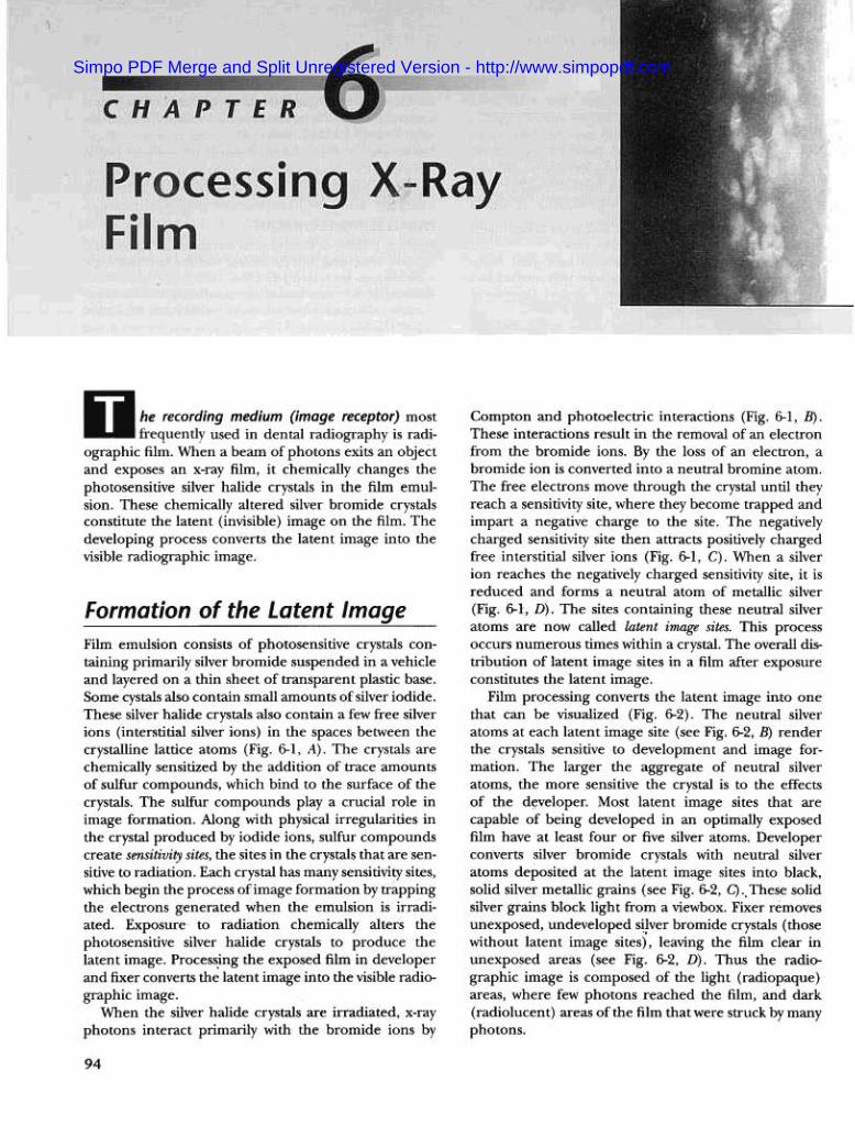
recording medium (image receptor) most., used in dental radiography is radi-
ographic film, When a beam of photons exits an objectand exposes an x-ray film, it chemically changes thephotosensitive silver halide crystals in the film emul-sion, These chemically altered silver bromide crystalsconstitute the latent (invisible) image on the film, Thedeveloping process converts the latent image into thevisible radiographic image,
Compton and photoelectric interactions (Fig. 6-1, B).These interactions result in the removal of an electronfrom the bromide ions. By the loss of an electron, abromide ion is converted into a neutral bromine atom.The free electrons move through the crystal until theyreach a sensitivity site, where they become trapped andimpart a negative charge to the site. The negativelycharged sensitivity site then attracts positively chargedfree interstitial silver ions (Fig. 6-1, C). When a silverion reaches the negatively charged sensitivity site, it isreduced and forms a neutral atom of metallic silver(Fig. 6-1, D). The sites containing these neutral silveratoms are now called latent image sites. This processoccurs numerous times within a crystal. The overall dis-tribution of latent image sites in a film after exposureconstitutes the latent image.
Film processing converts the latent image into onethat can be visualized (Fig. 6-2). The neutral silveratoms at each latent image site (see Fig. 6-2, B) renderthe crystals sensitive to development and image for-mation. The larger the aggregate of neutral silveratoms, the more sensitive the crystal is to the effectsof the d~veloper. Most latent image sites that arecapable of being developed in an optimally exposedfilm have at least four or five silver atoms. Developerconverts silver bromide crystals with neutral silveratoms deposited at the latent image sites into black,solid silver metallic grains (see Fig. 6-2, C).. These solidsilver grains block light from a viewbox. Fixer removesunexposed, undeveloped si~ver bromide crystals (thosewithout latent image sites), leaving the film clear inunexposed areas (see Fig. 6-2, D). Thus the radio-graphic image is composed of the light (radiopaque)areas, where few photons reached the film, and dark(radiolucent) areas of the film that were struck by many
photons.
Formation of the Latent Image
Film emulsion consists of photosensitive crystals con-taining primarily silver bromide suspended in a vehicleand layered on a thin sheet of transparent plastic base.Some cystals also contain small amounts of silver iodide.These silver halide crystals also contain a few free silverions (interstitial silver ions) in the spaces between thecrystalline lattice atoms (Fig. 6-1, A). The crystals arechemically sensitized by the addition of trace amountsof sulfur compounds, which bind to the surface of thecrystals. The sulfur compounds playa crucial role inimage formation. Along with physical irregularities inthe crystal produced by iodide ions, sulfur compoundscreate sensitivity sites, the sites in the crystals that are sen-sitive to radiation. Each crystal has many sensitivity sites,which begin the process of image formation by trappingthe electrons generated when the emulsion is irradi-ated. Exposure to radiation chemically alters thephotosensitive silver halide crystals to produce thelatent image. Process.ing the exposed film in developerand fixer converts the latent image into the visible radio-
graphic image.When the silver halide crystals are irradiated, x-ray
photons interact primarily with the bromide ions by
94
Simpo PDF Merge and Split Unregistered Version - http://www.simpopdf.com
95CHAPTER 6 PROCESSING X-RAY FILM
Sensitivity site
Latent image siteSensitivity site
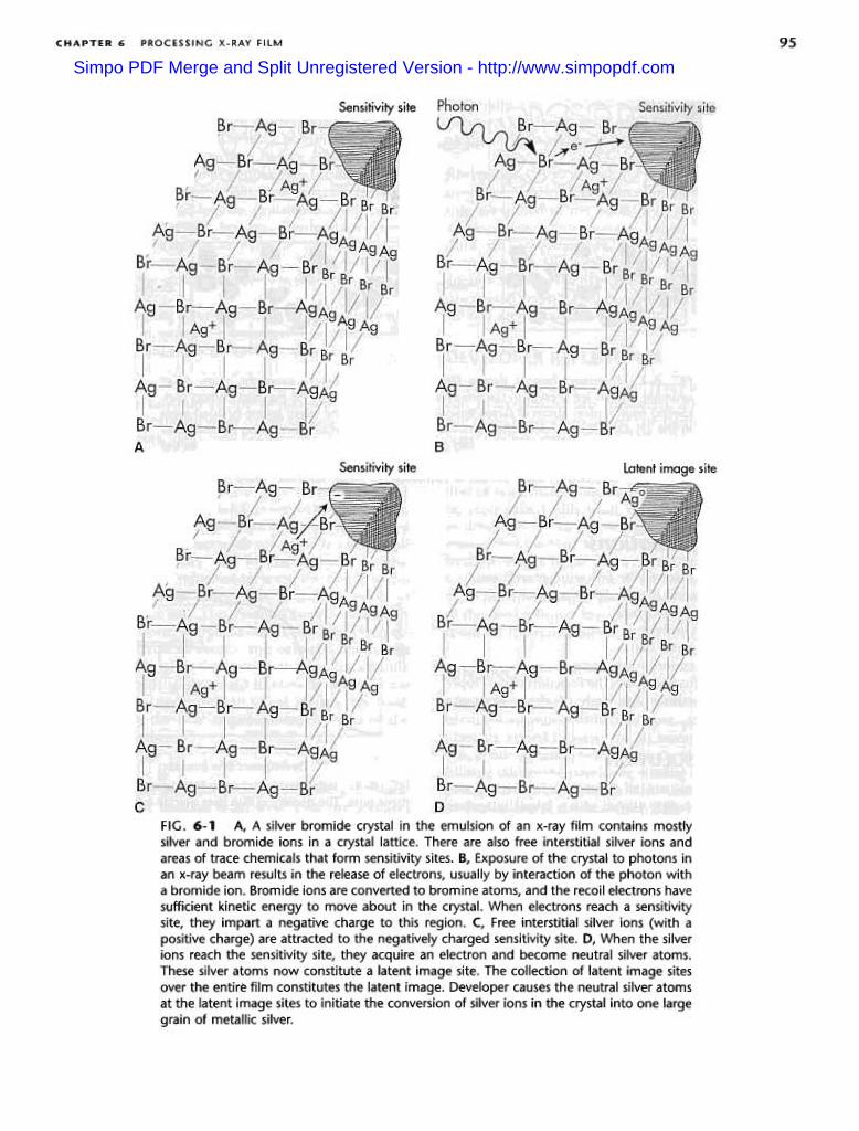
FIG. 6-1 A, A silver bromide crystal in the emulsion of an x-ray film contains mostlysilver and bromide ions in a crystal lattice. There are also free interstitial silver ions andareas of trace chemicals that form sensitivity sites. B, Exposure of the crystal to photons inan x-ray beam results in the release of electrons, usually by interaction of the photon witha bromide ion. Bromide ions are converted to bromine atoms, and the recoil electrons havesufficient kinetic energy to move about in the crystal. When electrons reach a sensitivitysite, they impart a negative charge to this region. C, Free interstitial silver ions (with apositive charge) are attracted to the negatively charged sensitivity site. D, When the silverions reach the sensitivity site, they acquire an electron and become neutral silver atoms.These silver atoms now constitute a latent image site. The collection of latent image sitesover the entire film constitutes the latent image. Developer causes the neutral silver atomsat the latent image sites to initiate the conversion of silver ions in the crystal into one largegrain of metallic silver.
Simpo PDF Merge and Split Unregistered Version - http://www.simpopdf.com
96 PART IV IMAGING PRINCIPLES AND TECHNIQUES
Emulsion Emulsion
B
I
Emulsion Emulsion
BaseD
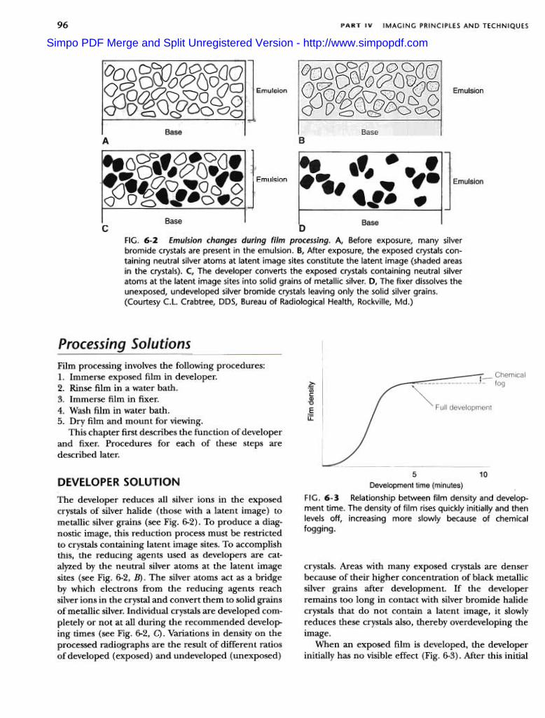
FIG. 6-2 Emulsion changes during film processing. A, Before exposure, many silverbromide crystals are present in the emulsion. 5, After exposure, the exposed crystals con-taining neutral silver atoms at latent image sites constitute the latent image (shaded areasin the crystals). C, The developer converts the exposed crystals containing neutral silveratoms at the latent image sites into solid grains of metallic silver. D, The fixer dissolves theunexposed, undeveloped silver bromide crystals leaving only the solid silver grains.(Courtesy C.L. Crabtree, DDS, Bureau of Radiological Health, Rockville, Md.)
c
2:-"Ujca>"0
§iI:
Film processing involves the following procedures:1. Immerse exposed film in developer.2. Rinse film in a water bath.3. Immerse film in fixer.4. Wash film in water bath.5. Dry film and mount for viewing.
This chapter first describes the function of developerand fixer. Procedures for each of these steps aredescribed later.
DEVELOPER SOLUTION
The developer reduces all silver ions in the exposedcrystals of silver halide (those with a latent image) tometallic silver grains (see Fig. 6-2). To produce a diag-nostic image, this reduction process must be restrictedto crystals containing latent image sites. To accomplishthis, the reducing agents used as developers are cat-alyzed by the neutral silver atoms at the latent imagesites (see Fig. 6-2, B). The silver atoms act as a bridgeby which electrons from the reducing agents reachsilver ions in the crystal and convert them to solid grainsof metallic silver. Individual crystals are developed com-pletely or not at all during the recommended develop-ing times (see Fig. 6-2, C). Variations in density on theprocessed radiographs are the result of different ratiosof developed (exposed) and undeveloped (unexposed)
5 10
Development time (minutes)
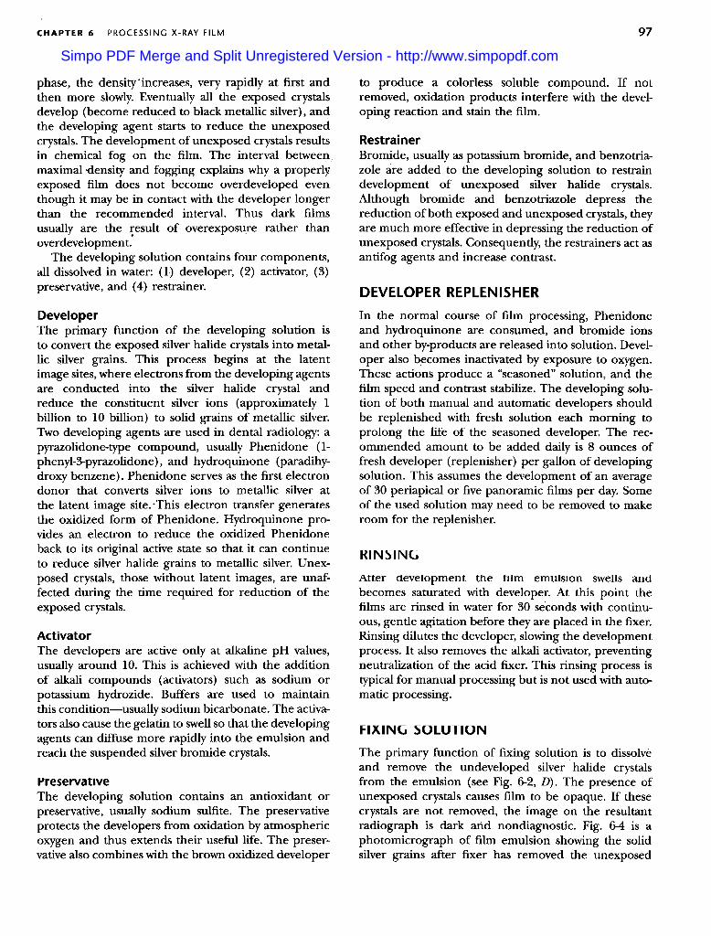
FIG. 6-3 Relationship between film density and develop-ment time. The density of film rises quickly initially and thenlevels off, increasing more slowly because of chemical
fogging.
crystals. Areas with many exposed crystals are denserbecause of their higher concentration of black metallicsilver grains after development. If the developerremains too long in contact with silver bromide halidecrystals that do not contain a latent image, it slowlyreduces these crystals also, thereby overdeveloping the
Image.When an exposed film is developed, the developer
initially has no visible effect (Fig. 6-3). Mter this initial
Simpo PDF Merge and Split Unregistered Version - http://www.simpopdf.com
CHAPTER 6 97PROCESSING X-RAY FILM
to produce a colorless soluble compound. If notremoved, oxidation products interfere with the devel-oping reaction and stain the film.
RestrainerBromide, usually as potassium bromide, and benzotria-zole are added to the developing solution to restraindevelopment of unexposed silver halide crystals.Although bromide and benzotriazole depress thereduction of both exposed and unexposed crystals, theyare much more effective in depressing the reduction ofunexposed crystals. Consequently, the restrainers act asantifog agents and increase contrast.
phase, the density'increases, very rapidly at first andthen more slowly. Eventually all the exposed crystalsdevelop (become reduced to black metallic silver), andthe developing agent starts to reduce the unexposedcrystals. The development of unexposed crystals resultsin chemical fog on the film. The interval betweenmaximal density and fogging explains why a properl';exposed film does not become overdeveloped eventhough it may be in contact with the developer longerthan the recommended interval. Thus dark filmsusually are the ~esult of overexposure rather than
overdevelopment.The developing solution contains four components,
all dissolved in water: (1) developer, (2) activator, (3)preservative, and (4) restrainer, DEVELOPER REPLENISHER
In the normal course of film processing, Phenidoneand hydroquinone are consumed, and bromide ionsand other by-products are released into solution. Devel-oper also becomes inactivated by exposure to oxygen.These actions produce a "seasoned" solution, and thefilm speed and contrast stabilize. The developing solu-tion of both manual and automatic developers shouldbe replenished with fresh solution each morning toprolong the life of the seasoned developer. The rec-ommended amount to be added daily is 8 ounces offresh developer (replenisher) per gallon of developingsolution. This assumes the development of an averageof 30 periapical or five panoramic films per day. Someof the used solution may need to be removed to makeroom for the replenisher.
DeveloperThe primary function of the developing solution isto convert the exposed silver halide crystals into metal-lic silver grains. This process begins at the latentimage sites, where electrons from the developing agentsare conducted into the silver halide crystal andreduce the constituent silver ions (approximately 1billion to 10 billion) to solid grains of metallic silver.Two developing agents are used in dental radiology: apyrazolidone-type compound, usually Phenidone (1-phenyl-3-pyrazolidone), and hydroquinone (paradihy-droxy benzene). Phenidone serves as the first electrondonor that converts silver ions to metallic silver atthe latent image site. 'This electron transfer generatesthe oxidized form of Phenidone. Hydroquinone pro-vides an electron to reduce the oxidized Phenidoneback to its original active state so that it can continueto reduce silver halide grains to metallic silver. Unex-posed crystals, those without latent images, are unaf-fected during the time required for reduction of the
e~posed crystals.
RINSING
Alter development the hIm emulsIon swells andbecomes saturated with developer. At this point thefilms are rinsed in water for 30 seconds with continu-ous, gentle agitation before they aye placed in the fixer.Rinsing dilutes the developer, slowing the developmentprocess. It also removes the alkali activator, preventingneutralization of the acid fixer. This rinsing process istypical for manual processing but is not used with auto-matic processing.
ActivatorThe developers are active only at alkaline pH values,usually around 10. This is achieved with the additionof alkali compounds (activators) such as sodium orpotassium hydrozide. Buffers are used to maintainthis condition-usually sodium bicarbonate. The activa-tors also cause the gelatin to swell so that the developingagents can diffuse more rapidly into the emulsion andreach the suspended silver bromide crystals.
FIXING SOLUTION
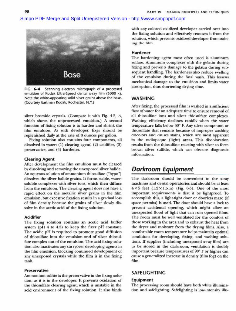
The primary function of fixing solution is to dissolveand remove the undeveloped silver halide crystalsfrom the emulsion (see Fig. 6-2, D). The presence ofunexposed crystals causes film to be opaque. If thesecrystals are not removed, the image on the resultantradiograph is dark and non diagnostic. Fig. 6-4 is aphotomicrograph of film emulsion showing the solidsilver grains after fixer has removed the unexposed
PreservativeThe developing solution contains an antioxidant orpreservative, usually sodium sulfite. The preservativeprotects the developers from oxidation by atmosphericoxygen and thus extends their useful life. The preser-vative also combines with the brown oxidized developer
Simpo PDF Merge and Split Unregistered Version - http://www.simpopdf.com
98 PART IV IMAGING PRINCIPLES AND TECHNIQUES
with any colored oxidized developer carried over intothe fixing solution and effectively removes it from thesolution, which prevents oxidized developer from stain-ing the film.
HardenerThe hardening agent most often used is aluminumsulfate. Aluminum complexes with the gelatin duringfixing and prevents damage to the gelatin during sub-sequent handling. The hardeners also reduce swellingof the emulsion during the final wash. This lessensmechanical damage to the emulsion and limits waterabsorption, thus shortening drying time.FIG. 6-4 Scanning electron micrograph of a processed
emulsion of Kodak Ultra-Speed dental x-ray film (5000 x).Note the white-appearing solid silver grains above the base.(Courtesy Eastman Kodak, Rochester, N.Y.)
WASHING
Mter fixing, the processed film is washed in a sufficientflow of water for an adequate time to ensure removal ofall thiosulfate ions and silver thiosulfate complexes.Washing efficiency declines rapidly when the watertemperature falls below 600 F. Any silver compound orthiosulfate that remains because of improper washingdiscolors and causes stains, which are most apparentin the radiopaque (light) areas. This discolorationresults from the thiosulfate reacting with silver to formbrown silver sulfide, which can obscure diagnosticinformation.
silver bromide crystals. (Compare it with Fig. 4-2, A,which shows the unprocessed emulsion.) A secondfunction of fixing solution is to harden and shrink thefilm emulsion. As with developer, fix:er should bereplenished daily at the rate of 8 ounces per gallon.
Fixing solution also contains four components, alldissolved in water: (1) cle~Jing agent, (2) acidifier, (3)preservative, and (4) hardener.
Clearing AgentMter development the film emulsion must be clearedby dissolving and removing the unexposed silver halide.An aqueous solution of ammonium thiosulfate ("hypo")dissolves the silver halide grains. It forms stable, water-soluble complexes with silver ions, which then diffusefrom the emulsion. The clearing agent does not have arapid effect on the metallic silver grains in the filmemulsion, but excessive fixation results in a gradual lossof film density because the grains of silver slowly dis-solve in the acetic acid of the fixing solution.
The darkroom should be convenient to the x-raymachines and dental operatories and should be at least4 x 5 feet (1.2 x 1.5m) (Fig. 6-5). One of the mostimportant requirements is that it be lightproof. Toaccomplish this, a light-tight door or doorless maze (ifspace permits) is used. The door should have a lock toprevent accidental opening, which might allow anunexpected flood of light that can ruin opened films.The room must be well ventilated for the comfort ofthose working in the area and to exhaust the heat fromthe dryer and moisture from the drying films. Also, acomfortable room temperature helps maintain optimalconditions for developing, fixing, and washing solu-tions. If supplies (including unexposed x-ray film) areto be stored in the darkroom, ventilation is doublyimportant because temperatures of 900 F or higher cancause a generalized increase in density (film fog) on thefilm.
AcidifierThe fixing solution contains an acetic acid buffersystem (pH 4 to 4.5) to keep the fixer pH constant.The acidic pH is required to promote good diffusionof thiosulfate into the emulsion and of silver thiosul-fate complex out of the emulsion. The acid fixing solu-tion also inactivates any carryover developing agents inthe film emulsion, blocking continued development ofany unexposed crystals while the film is in the fixingtank.
PreservativeAmmonium sulfite is the preservative in the fixing solu-tion, as it is in the developer. It prevents oxidation ofthe thiosulfate clearing agent, which is unstable in theacid environment of the fixing solution. It also binds
SAFEllGHTING
EquipmentThe processing room should have both white illumina-tion and safelighting. Safelighting is low-intensity illu-
Simpo PDF Merge and Split Unregistered Version - http://www.simpopdf.com
\99CHAPTER 6 PROCESSING X-RAY FILM
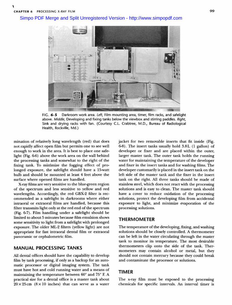
FIG. 6-5 Darkroom work area. Left, Film mounting area, timer, film racks, and safelightabove. Middle, Developing and fixing tanks below the viewbox and stirring paddles. Right,Sink and drying racks with fan. (Courtesy C.L. Crabtree, M.D" Bureau of Radiological
Health, Rockville, Md.)
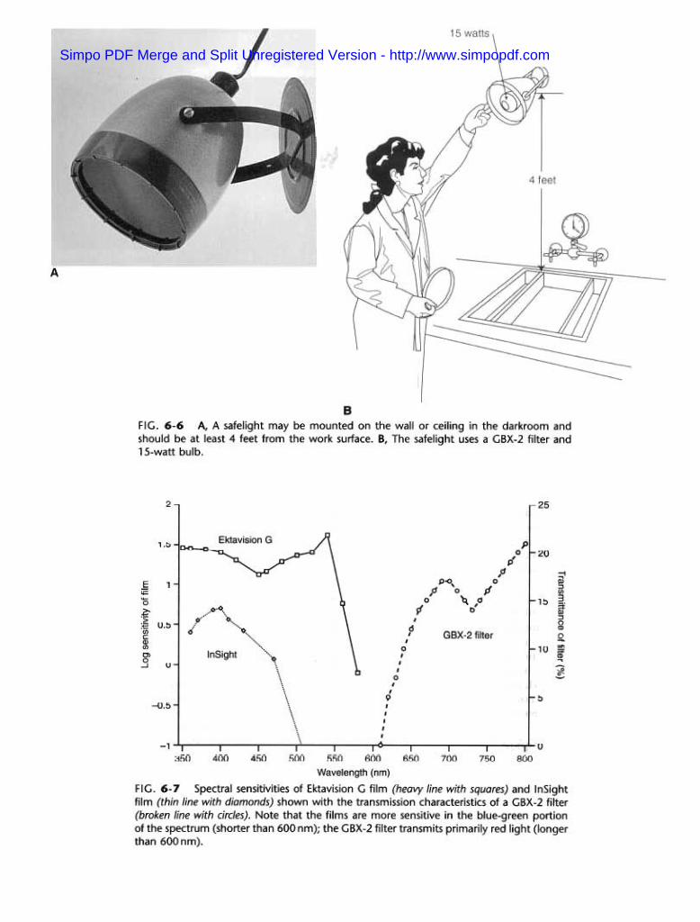
mination of relatively long wavelength (red) that doesnot rapidly affect open film but permits one to see wellenough to work in the area. It is best to place one safe-light (Fig. 6-6) above the work area on the wall behindthe processing tanks and somewhat to the right of thefixing tank. To minimize the fogging effect of pro-longed exposure, the safelight should have a I5-wattbulb and should be mounted at least 4 feet above thesurface where opened films are handled.
X-ray films are very sensitive to the blue-green regionof the spectrum and less sensitive to yellow and redwavelengths. Accordingly, the red GBX-2 filter is rec-omIIiended as a safelight in darkrooms where eitherintraoral or extraoral films are handled, because thisfilter transmits light only at the red end of the spectrum(Fig. 6-7). Film handling under a safelight should belimited to about 5 minutes because film emulsion showssome sensitivity to light from a safelight with prolongedexposure. The older ML-2 filters (yellow light) are notappropriate for fast intraoral dental film or extraoralpanoramic or cephalometric film.
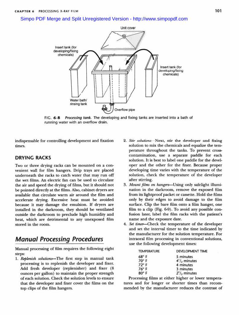
jacket for two removable inserts that fit inside (Fig.6-8). The insert tanks usually hold 3.8L (1 gallon) ofdeveloper or fixer and are placed within the outer,larger master tank. The outer tank holds the runningwater for maintaining the temperature of the developerand fixer in the insert tanks and for washing films. Thedeveloper customarily is placed in the insert tank on theleft side of the master tank and the fixer in the inserttank on the right. All three tanks should be made ofstainless steel, which does not react with the processingsolutions and is easy to clean. The master tank shouldhave a cover to reduce oxidation of the processingsolutions, protect the developing film from accidentalexposure to light, and minimize evaporation of theprocessing solutions.
THERMOMETER
The temperature of the developing, fixing, and washingsolutions should be closely controlled. A thermometercan be left in the water circulating through the mastertank to monitor its temperature. The most desirablethermometers clip onto the side of the tank. Ther-mometers may contain alcohol or metal, but theyshould not contain mercury because they could breakand contaminate the processor or solutions.
MANUAL PROCESSING TANKS
All dental offices should have the capability to developfilm by tank processing, if only as a backup for an auto-matic processor or digital imaging system. The tankmust have hot and cold running water and a means ofmaintaining the temperature between 600 and 750 F. Apractical size for a dental office is a master tank about20 x 25cU1 (8 x 10 inches) that can serve as a water
TIMER
The x-ray film must be exposed to the processingchemicals for specific intervals. An interval timer is
Simpo PDF Merge and Split Unregistered Version - http://www.simpopdf.com
A
BFIG. 6-6 A, A safelight may be mounted on the wall or ceiling in the darkroom andshould be at least 4 feet from the work surface. B, The safelight uses a GBX-2 filter and15-watt bulb.
2 25
l.b20
-i~:J(I)
3a-S!):JnCD'"'
~'0:;.~"inc:Q)(/)
OJ0
-l
,1::>
U.b -10 ==
~~.2...
u
b-0.5
-1 uJbU 4UU 4bU bUU 55U 6UO 650 700 750 800
Wavelength (nm)
FIG. 6-7 Spectral sensitivities of Ektavision G film (heavy line with squares) and InSightfilm (thin line with diamonds) shown with the transmission characteristics of a GBX-2 filter(broken line with circles). Note that the films are more sensitive in the blue-green portionof the spectrum (shorter than 600 nm); the GBX-2 filter transmits primarily red light (longerthan 600 nm).
Simpo PDF Merge and Split Unregistered Version - http://www.simpopdf.com
101PROCESSING X-RAY FILMCHAPTER 6
Unit cover
~
/I
tInsert tank (fordeveloping/fixing
chemicals) ~,' , I " ,
,::.../Insert tank (for
developing/fixingchemicals)
// /
IWater bath/rinsing tank ~
FIG. 6-8 Processing tank. The developing and fixing tanks are inserted into a bath ofrunning water with an overflow drain.
Overflow pipe
indispensable for controlling development and fixationtimes.
DRYING RACKS
Two or three drying racks can be mounted on a con-venient wall for film hangers. Drip trays are placedunderneath the racks to catch water that may run offthe wet films. An electric fan can be used to circulatethe air and speed the drying of films, but it should notbe pointed directly at the films. Also, cabinet dryers areavailable that circulate warm air around the film andaccelerate drying. Excessive heat must be avoidedbecause it may damage the emulsion. If dryers areinstalled in the darkroom, they should be ventilatedoutside the darkroom to preclude high humidity andheat, which are detrimental to any unexposed filmstored in the room.
Manual processing of film requires the following eight
steps:1. Replenish solutio~The first step in manual tank
processing is to replenish the developer and fixer.Add fresh developer (replenisher) and fixer (8ounces per gallon) to maintain the proper strengthof each solution. Check the solution levels to ensurethat the developer and fixer cover the films on thetop clips of the film hangers.
2. Stir solutions-Next, stir the developer and fixingsolution to mix the chemicals and equalize the tem-perature throughout the tanks. To prevent cross-contamination, use a separate paddle for eachsolution. It is best to label one paddle for the devel-oper and the other for the fixer. Because properdeveloping time varies with the temperature of thesolution, check the temperature of the developerafter stirring.
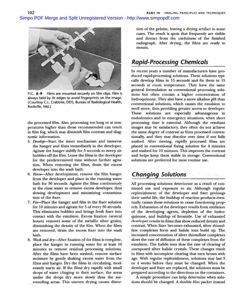
3. Mount films on hangers-Using only safelight illumi-nation in the darkroom, remove the exposed filmfrom its lightproof packet or cassette. Hold the filmsonly by their edges to avoid damage to the filmsurface. Clip the bare film onto a film hanger, onefilm to a clip {Fig. 6-9). To avoid any possible con-fusion later, label the film racks with the patient'sname and the exposure date.
4. Set timer-Check the temperature of the developerand set the interval timer to the time indicated bythe manufacturer for the solution temperature. Forintraoral film processing in conventional solutions,use the following development times:
TEMPERATURE DEVELOPMENT TIME
680 F 5 minutes700 F 4'/2 minutes720 F 4 minutes760 F 3 minutes800 F 21/2 minutes
Processing films at either higher or lower tempera-tures and for longer or shorter times than recom-mended by the manufacturer reduces the contrast of
Simpo PDF Merge and Split Unregistered Version - http://www.simpopdf.com
IMAGING PRINCIPLES AND TECHNIQUESPART IV102
tion of the gelatin, leaving a drying artifact in somecases. The result is spots that frequently are visibleand detract from the usefulness of the finishedradiograph. Mter drying, the films are ready tomount.
---
FIG. 6-9 Films are mounted securely on film clips. Film isalways held by its edges to avoid fingerprints on the image.(Courtesy C.L. Crabtree, DDS, Bureau of Radiological Health,
Rockville, Md.)
the processed film. Also, processing too long or at tem-peratures higher than those recommended can resultin film fog, which may diminish film contrast and diag-nostic information.5. Develop-Start the timer mechanism and immerse
the hanger and films immediately in the developer.Agitate the hanger mildly for 5 seconds to sweep airbubbles off the film. Leave the films in the developerfor the predetermined time without further agita-tion. When removing the films, drain the excessdeveloper into the wash bath.
6. Rinse-After development, remove the film hangerfrom the developer and place in the running waterbath for 30 seconds. Agitate ,the films continuouslyin the rinse water to remove excess developer, thusslowing development and minimizing contamina-tion of the fixer.
7. Fix-Place the hanger and film in the fixer solutionfor 10 minutes and agitate for 5 of every 30 seconds.This eliminates bubbles and brings fresh fixer intocontact with the emulsion. Excess fixation (severalhours) removes some of the metallic silver grains,diminishing the density of the film. When the filmsare removed, drain the excess fixer into the washbath.
8. Wash and dry-After fixation of the films is complete,place the hanger in running water for at least 10minutes to remove residual processing solutions.After the films have been washed, remove surfacemoisture by gently shaking excess water from thefilms and hanger. Dry the films in circulating, mod-erately warm air. If the films dry rapidly with smalldrops of water clinging to their surface, the areasunder the drops dry more slowly than the sur-rounding areas. This uneven drying causes distor-
In recent years a number of manufacturers have pro-duced rapid-processing solutions. These solutions typi-cally develop films in 15 seconds and fix them in 15seconds at room temperature. They have the samegeneral formulation as conventional processing solu-tions but often contain a higher concentration ofhydroquinone. They also have a more alkaline pH thanconventional solutions, which causes the emulsion toswell more, thus providing greater access to developer.These solutions are especially advantageous inendodontics and in emergency situations, when shortprocessing time is essential. Although the resultantimages may be satisfactory, they often do not achievethe same degree of contrast as films processed conven-tionally, and they may discolor over time if not fullywashed. Mter viewing, rapidly processed films areplaced in conventional fixing solution for 4 minutesand washed for 10 minutes. This improves the contrastand helps keep them stable in storage. Conventionalsolutions are preferred for most routine use.
All processing solutions deteriorate as a result of con-tinued use and exposure to air. Although regularreplenishment of the developer and fixer prolongstheir useful life, the buildup of reaction products even-tually causes these solutions to cease functioning prop-erly. Exhaustion of the developer results from oxidationof the developing agents, depletion of the hydro-quinone, and buildup of bromide. Use of exhausteddeveloper results in films that show reduced density andcontrast. When fixer becomes exhausted, silver thiosul-fate complexes form and halide ions build up. Theincreased concentration of silver thiosulfate complexesslows the rate of diffusion of these complexes from theemulsion. The halide ions slow the rate of clearing ofunexposed silver halide crystals. These changes resultin films with incomplete clearing that turn brown withage. With regular replenishment, solutions may last 3or 4 weeks before they must be changed. When thedeveloper and fixer are replaced, the solutions must beprepared according to the directions on the containers.
A simple procedure can help determine when solu-tions should be changed. A double film packet instead
Simpo PDF Merge and Split Unregistered Version - http://www.simpopdf.com
103PROCESSING X-RAY FILMCHAPTER 6
of a single film packet is exposed on one projection forthe first patient radiographed after new solutions havebeen prepared. One film is placed in the patient'schart, and the other is mounted on a corner of aviewbox in the darkroom. As successive films areprocessed, they are compared with this reference ~l~ ,;Loss of image contrast and density become evident as"''the solutions deteriorate, indicating when the time hascome to change them. The fixer is changed when thedeveloper is changed.
attractive feature of the automatic system is that thedensity and contrast of the radiographs tend to be con-sistent. However, because of the higher temperature ofthe developer and the artifacts caused by rollers, thequality of films processed automatically often is not ashigh as that of those carefully developed manually. Withautomatically processed films, more grain usually isevident in the final image.
Whether automatic processing equipment is appro-priate for a specific practice depends on the dentist andthe nature and volume of the practice. The equipmentis expensive and must be cleaned frequently. Also, theautomated equipment may break down, and conven-tional darkroom ~quipment may still be needed as abackup system.
Automatic Film Processing
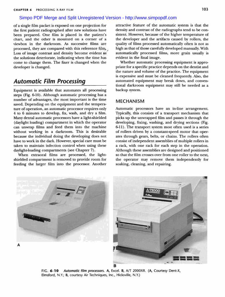
Equipment is available that automates all processingsteps (Fig. 6-10). Although automatic processing has anumber of advantages, the most important is the timesaved. Depending on the equipment and the tempera-ture of operation, an automatic processor requires only4 to 6 minutes to develop, fix, wash, and dry a film.Many dental automatic processors have a light-shielded(daylight loading) compartment in which the operatorcan unwrap films and feed them into the machinewithout working in a darkroom. This is desirablebecause the individual doing the developing does nothave to work in the dark. However, special care must betaken to maintain infection control when using thesedaylight-loading compartments (see Chapter 7).
When extraoral films are processed, the light-shielded compartment is removed to provide room forfeeding the larger film into the processor. Another
MECHANISM
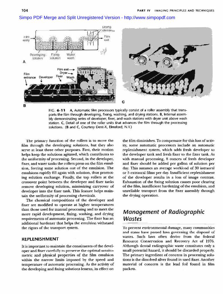
Automatic processors have an in-line arrangement.Typically, this consists of a transport mechanism thatpicks up the unwrapped film and passes it through thedeveloping, fixing, washing, and drying sections (Fig.6-11). The transport system most often used is a seriesof rollers driven by a constant-speed motor that oper-ates through gears, belts, or chains. The rollers oftenconsist of independent assemblies of multiple rollers ina rack, with one rack for each step in the operation.Although these assemblies are designed and positionedso that the film crosses over from one roller to the next,the operator may remove them independently forsoaking, cleaning, and repairing.
A
BFIG. 6-10 Automatic film processors. A, Excel. B, AfT 2000XR. (A, Courtesy Dent-X,Elmsford, N.Y.; B, courtesy Air Techniques, Inc., Hicksville, N.Y.)
Simpo PDF Merge and Split Unregistered Version - http://www.simpopdf.com
104 PART IV IMAGING PRINCIPLES AND TECHNIQUES
Film exit-+Film Dryer-..entrance Developer Fixer Wash\ .! \
cB
FIG. 6-11 A, Automatic film processors typically consist of a roller assembly that trans-ports the film through developing, fixing, washing, and drying stations. B, Internal assem-bly demonstrating series of developer, fixer, and wash stations with dryer unit above washstation. C, Detail of one of the roller units that advances the film through the processingsolutions. (B and C, Courtesy Dent-X, Elmsford, N.Y.)
the film diminishes. To compensate for this loss of activ-ity, some automatic processors include an automaticreplenishment system, which adds fresh developer tothe developer tank and fresh fixer to the fixer tank. Aswith manual processing, 8 ounces of fresh developerand fixer should be added per gallon of solution perday. This assumes an average workload of 30 intraoralor 5 extraoral films per day. Insufficient replenishmentof the developer results in a loss of image contrast.Exhaustion of the fixing solution causes poor clearingof the film, insufficient hardening of the emulsion, andunreliable transport from the fixer assembly throughthe drying operation.
'[he primary function of the rollers is to move thefilm through the developing solutions, but they alsoserve at least three other purposes. First, their motionhelps keep the solutions agitated, which contributes tothe uniformity of processing. Second, in the developer,fixer, and water tanks the rollers press on the film emul-sion, forcing some solution out of the emulsion. Theemulsions rapidly fill again with solution, thus promot-ing solution exchange. Finally, the top rollers at thecrossover point between the developer and fixer tanksremove developing solution, minimizing carryover ofdeveloper into the fixer tank. This feature helps main-tain the uniformity of processing chemicals.
The chemical compositions of the developer andfixer are modified to operate at higher temperaturesthan those used for manual processing and to meet themore rapid development, fixing, washing, and dryingrequirements of automatic processing. The fixer has anadditional hardener that helps the emulsion withstandthe rigors of the transport system.
Management of RadiographicWastes
-
'10 prevent environmental dama,ge, many communitiesand states have passed laws governing the disposal ofwastes. Such laws often derive from the federalResource Conservation and Recovery Act of 1976.Although dental radiographic waste constitutes only asmall potential hazard, it should be discarded properly.The primary ingredient of concern in processing solu-tions is the dissolved silver found in used fixer. Anothermaterial of concern is the lead foil found in filmpackets.
REPLENISHMENT
It is important to maintain the constituents of the devel-oper and fixer carefully to preserve the optimal sensito-metric and physical properties of the film emulsionwithin the narrow limits imposed by the speed andtemperature of automatic processing. As the activity ofthe developing and fixing solutions lessens, its effect on
Simpo PDF Merge and Split Unregistered Version - http://www.simpopdf.com
,105PROCESSING X-RAY FILMCHAPTER 6
The names of such companies can be found in the tele-phone directory or obtained from the state hazardouswaste management agency.
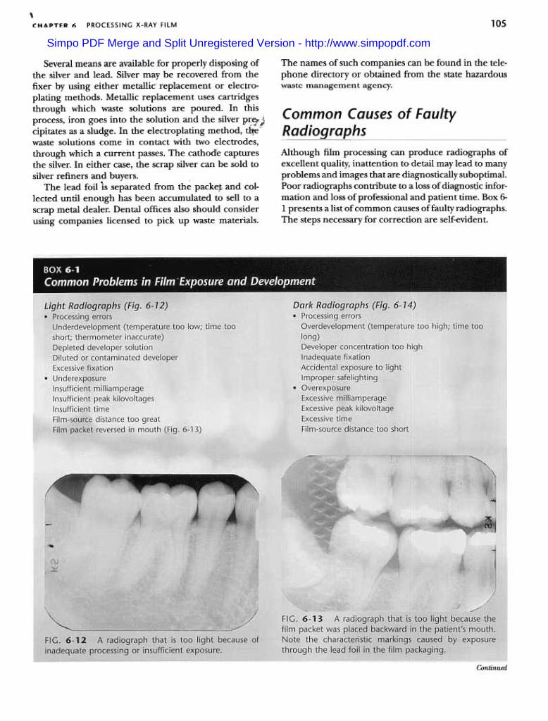
Although film processing can produce radiographs ofexcellent quality, inattention to detail may lead to manyproblems and images that are diagnostically suboptimal.Poor radiographs contribute to a loss of diagnos~c infor-mation and loss of professional and patient time. Box 6-1 presents a list of common causes of faulty radiographs.The steps necessary for correction are self-evident.
Several means are available for properly disposing ofthe silver and lead. Silver may be recovered from thefixer by using either metallic' replacement or electro-plating methods. Metallic replacement uses cartridgesthrough which waste solutions are poured. In thisprocess, iron goes into the solution and the silver pre" ,;,
~,,$!cipitates as a sludge. In the electroplating method, t~'waste solutions come in contact with two electrodes,through which a current passes. The cathode capturesthe silver. In either case, the scrap silver can be sold tosilver refiners and buyers.
The lead foil "is separated from th~ packe~ and col-lected until enough has been accumulated to sell to ascrap metal dealer. Dental offices also should considerusing companies licensed to pick up waste materials.
Continued
Simpo PDF Merge and Split Unregistered Version - http://www.simpopdf.com

106 PART IV IN' ANi
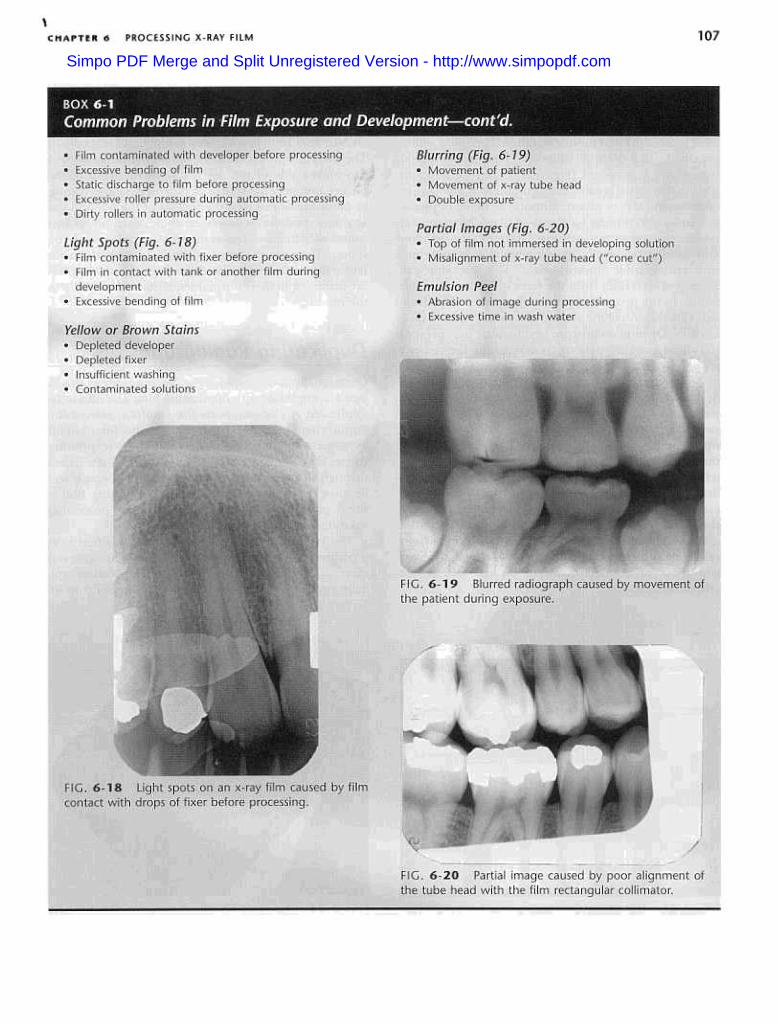
Insufficient Contrast (Fig. 6- 75) Film Fog (Fig. 6-16)
.Improper safelighting (improper filter; excessive bulbwattage; inadequate distance between safelight andwork surface; prolonged exposure to safelight)
.Light leaks (cracked safelight filter; light from doors,vents, or other sources)
.Overdevelopment.Contaminated solutions.Deteriorated film (stored at high temperature; stored
at high humidity; exposed to radiation; outdated)
Dark Spats or Lines (Fig. 6-17).Fingerprint contamination
.Black wrapping paper sticking to film surface
.Film in contact with tank or another film during
fixation
FIG.6-16detail.
Fogged radiograph marked by lack of image
FIG. 6-14 A radiograph that is too dark because ofoverdevelopment or overexposure.
FIG. 6-15 A radiograph with insufficient contrast,showing gray enamel and gray pulp chambers.
FIG. 6-17 Dark spot on an x-ray film caused by filmcontact with the tank wall during fixation.
.Underdevelopment
.Underexposure.Excessive peak kilovoltage
.Excessive film fog
Simpo PDF Merge and Split Unregistered Version - http://www.simpopdf.com
\107PROCESSING X-RAY FILMCHAPTER 6
Simpo PDF Merge and Split Unregistered Version - http://www.simpopdf.com
lnR PART 1\1 IMAGING PRINCIPLES AND TECHNIQUES
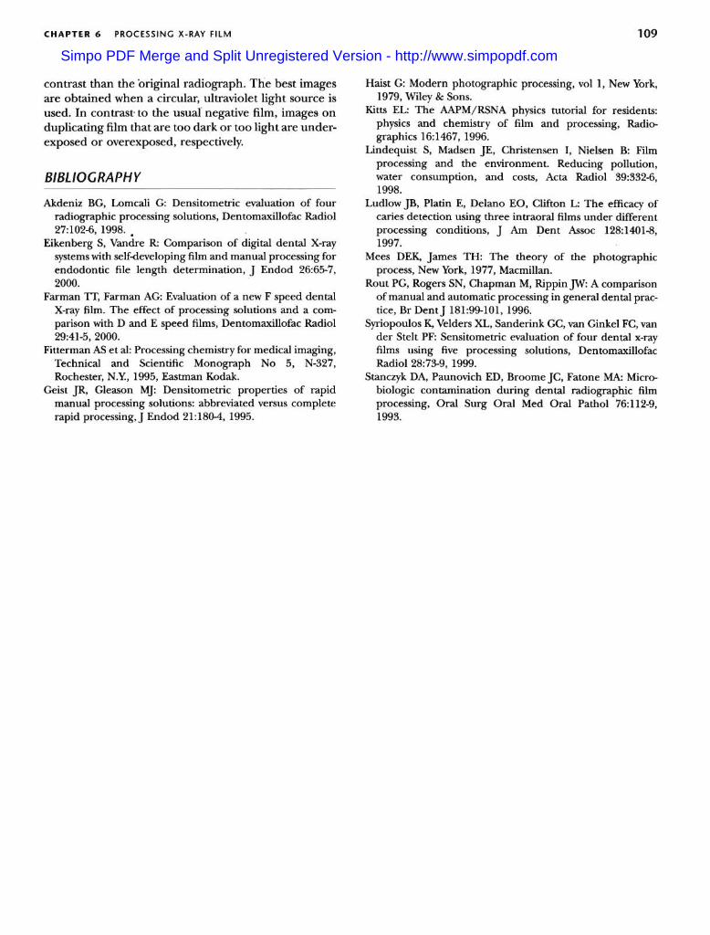
Identification Dot
A round impression in a corner of each film, the "dot,"allows rapid and proper film orientation (Fig. 6-22).The manufacturer orients the film in the packet so thatthe convex side of the dot is toward the front of thepacket and faces the source of radiation. Consequently,to mount the films with the images of the teeth in theanatomic position as described above, each film is firstoriented with the convex side of the dot toward theviewer. Then, on the basis of the features of the teethand anatomic landmarks in the adjacent bone, the filmsare arranged in their normal sequential relationship inthp mOllnt
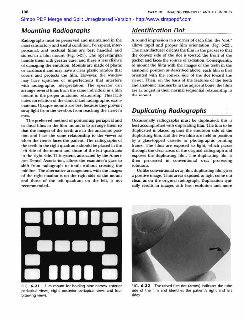
Radiographs must be preserved and maintained in themost satisfactory and useful condition. Periapical, inter-proximal, and occlusal films are best handled andstored in a film mount (Fig. 6-21). The operatQ(!panhandle them with greater ease, and there is less cIlanceof damaging the emulsion. Mounts are made of plasticor cardboard and may have a clear plastic window thatcovers and protects the film. However, the windowmay have sc.ratches or imperfections that interferewith radiographic interpretation. The operator canarrange several films from the same individual in a filmmount in the proper anatomic relationship. This facil-itates correlation of the clinical and radiographic exam-inations. Opaque mounts are best because they preventstray light from the viewbox from reaching the viewer's
eyes.The preferred method of positioning periapical and
occlusal films in the film mount is to arrange them sothat the images of the teeth are in the anatomic posi-tion and have the same relationship to the viewer aswhen the viewer faces the patient. The radiographs ofthe teeth in the right quadrants should be placed in theleft side of the mount and those of the left quadrantsin the right side. This system, advocated by the Ameri-can Dental Association, allows the examiner's gaze toshift from radiograph to tooth without crossing themidline. The alternative arrangement, with the imagesof the right quadrants on the right side of the mountand those of the left quadrant on the left, is notrecommended.
FIG. 6-21 Film mount for holding nine narrow anteriorperiapical views, eight posterior periapical view, and fourbitewing views.
FIG. 6-22 The raised film dot (arrow) indicates the tubeside of the film and identifies the patient's right and leftsides.
Occasionally radiographs must be duplicated; this isbest accomplished with duplicating film. The film to beduplicated is placed against the emulsion side of theduplicating film, and the two films are held in positionby a glass-topped cassette or photographic printingframe. The films are exposed to light, which passesthrough the clear areas of the original radiograph andexposes the duplicating film. The duplicating film isthen processed in conventional x-ray processingsolutions.
Unlike conventional x-ray film, duplicating film givesa positive image. Thus areas exposed to light come outclear, as on the original radiograph. Duplication typi-cally results in images with less resolution and more
Simpo PDF Merge and Split Unregistered Version - http://www.simpopdf.com
109CHAPTER 6 PROCESSING X-RAY FILM
contrast than the 'original radiograph. The best imagesare obtained when a circular, ultraviolet light source isused. In contrast to the usual negative film, images onduplicating film that are too dark or too light are under-exposed or overexposed, respectively.
BIBLIOGRAPHY
Haist G: Modern photographic processing, vol 1, New York,1979, Wiley & Sons.
Kitts EL: The AAPMjRSNA physics tutorial for residents:physics and chemistry of film and processing, Radio-graphics 16:1467, 1996.
Lindequist S, Madsen JE, Christensen I, Nielsen B: Filmprocessing and the environment. Reducing pollution,water consumption, and costs, Acta Radiol 39:332-6,1998.
Ludlow JB, Platin E, Delano EO, Clifton L: The efficacy ofcaries detection using three intraoral films under differentprocessing conditions, J Am Dent Assoc 128:1401-8,1997.
Mees DEK, James TH: The theory of the photographicprocess, New York, 1977, Macmillan.
Rout PC, Rogers SN, Chapman M, RippinJW: A comparisonof manual and automatic processing in general dental prac-tice, Br DentJ 181:99-101, 1996.
Syriopoulos K, Velders XL, Sanderink GC, van Ginkel FC, vander Stelt PF: Sensitometric evaluation of four dental x-rayfilms using five processing solutions, DentomaxillofacRadiol 28:73-9, 1999.
Stanczyk DA, Paunovich ED, Broome JC, Fatone MA: Micro-biologic contamination during dental radiographic filmprocessing, Oral Surg Oral Med Oral Pathol 76:112-9,1993.
Akdeniz BG, Lomcali G: Densitometric evaluation of fourradiographic processing solutions, Dentomaxillofac Radiol27:102-6, 1998. .
Eikenberg S, Vandre R: Comparison of digital dental X-raysystems with self-developing film and manual processing forendodontic file length determination, J Endod 26:65-7,2000.
Farman n, Farman AG: Evaluation of a new F speed dentalX-ray film. The effect of processing solutions and a com-parison with D and E speed films, Dentomaxillofac Radiol29:41-5,2000.
Fitterman AS et al: Processing chemistry for medical imaging,Technical and Scientific Monograph No 5, N-327,Rochester, N.Y, 1995, Eastman Kodak.
Geist JR, Gleason MJ: Densitometric properties of rapidmanual processing solutions: abbreviated versus completerapid processing,J Endod 21:180-4,1995.
Simpo PDF Merge and Split Unregistered Version - http://www.simpopdf.com