formation pressure - famanchemie|drilling mud addetivesfamanchemie.com/uploads/literature1/formation...
TRANSCRIPT

1
Formation Pressure
By:Saeed Fakhr

PressurePressure is defined as force per unit area:
𝐏𝐫𝐞𝐬𝐬𝐫𝐞 =𝐅𝐨𝐫𝐜𝐞
𝐀𝐫𝐞𝐚
𝐏 𝐩𝐬𝐢 =𝐅(𝐈𝐛)
𝐀(𝐢𝐧.𝟐 )
𝐏 𝐛𝐚𝐫 =𝐅(𝐝𝐲𝐧)
𝐀(𝐜𝐦𝟐)𝐏 𝐏𝐚 =
𝐅(𝐍)
𝐀(𝐦𝟐)
𝟏 𝐛𝐚𝐫 = 𝟏𝟎𝟓 𝐏𝐚 = 𝟏𝟒. 𝟓𝟎𝟑𝟕𝟕 𝐩𝐬𝐢

Density and Specific GravityThe density of a substance is its mass per unit volume:
𝝆 =𝒎
𝑽
𝟏𝒑𝒑𝒈 = 𝟕. 𝟒𝟖𝟎𝟔𝟖 𝒑𝒄𝒇 = 𝟏𝟏𝟗. 𝟖𝟑 Τ𝒌𝒈 𝒎𝟑
𝒑𝒑𝒈 = Τ𝑰𝒃 𝒈𝒂𝒍𝒑𝒄𝒇 = Τ𝑰𝒃 𝒊𝒏.𝟑
Specific gravity is the ratio of the density of a substance to the density of a reference substance. The reference substance is nearly always water at its densest (4°C)
𝑺𝑮 =𝝆
𝝆𝒘𝒂𝒕𝒆𝒓
𝝆𝒘𝒂𝒕𝒆𝒓 = 𝟏 Τ𝒌𝒈 𝒎𝟑 𝝆( Τ𝒌𝒈 𝒎𝟑) = 𝑺𝑮𝝆𝒘𝒂𝒕𝒆𝒓 = 𝟖. 𝟑𝟐 𝒑𝒑𝒈𝝆 𝒑𝒑𝒈 = 𝑺𝑮 × 𝟖. 𝟑𝟐

Hydrostatic PressureThe pressure at a given depth in a static liquid is a result the weight of the liquid acting on a unit area at that depth plus any pressure acting on the surface of the liquid
𝑷𝑯𝒀𝑫 = 𝝆 × 𝒈 × 𝒉
• The pressure at a given depth is independent of direction .it is the same in all directions

• The pressure at a given depth does not depend upon the shape of the vessel containing the liquid or the amount of liquid in the vessel.
𝑷𝑯𝒀𝑫 = 𝝆 × 𝒈 × 𝑻𝑽𝑫

Hydrostatic Pressure In Drilling wellsHydrostatic pressure (𝑷𝑯𝒀𝑫) is the pressure caused by the density or Mud Weight (𝑴𝑾) and True Vertical Depth (𝑻𝑫𝑽) of a column of fluid. The hole size and shape of the fluid column have no effect on hydrostatic pressure.
𝑷𝑯𝒀𝑫 = 𝟎. 𝟎𝟓𝟐 ×𝑴𝑾× 𝑻𝑽𝑫
𝑷𝑯𝒀𝑫= Hydrostatic Pressure (𝒑𝒔𝒊)
𝑴𝑾 =mud Density (𝒑𝒑𝒈)
𝑻𝑽𝑫 =true vertical depth(𝒇𝒕)
𝑴𝑫= measured depth(𝒇𝒕)

Weight MaterialWeighting materials (densifiers) are compounds that are dissolved or suspended in drilling fluid to increase its density. Any substance that is denser than water and that does not adversely affect other properties of the drilling fluid can be used as a weighting material.
Suspend Solid weighting material
Material Principle ComponentSpecial
Gravity
Galena 𝑷𝒃𝑺 6.6
Hematite 𝑭𝒆𝟐𝑶𝟑 5
Barite 𝑩𝒂𝑺𝑶𝟑 4.2
Limestone 𝑪𝒂𝑪𝑶𝟑 2.7
Bentonite --- 2.6
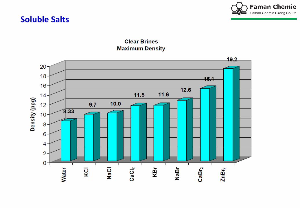
Soluble Salts


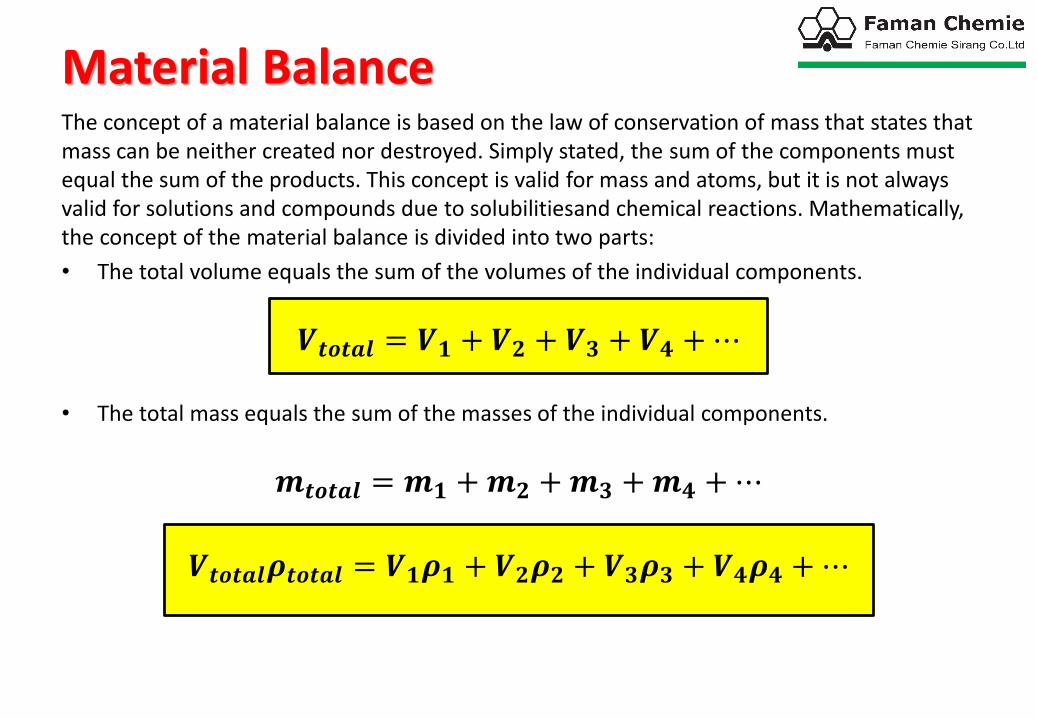
Material BalanceThe concept of a material balance is based on the law of conservation of mass that states that mass can be neither created nor destroyed. Simply stated, the sum of the components must equal the sum of the products. This concept is valid for mass and atoms, but it is not always valid for solutions and compounds due to solubilitiesand chemical reactions. Mathematically, the concept of the material balance is divided into two parts:
• The total volume equals the sum of the volumes of the individual components.
𝑽𝒕𝒐𝒕𝒂𝒍 = 𝑽𝟏 + 𝑽𝟐 + 𝑽𝟑 + 𝑽𝟒 +⋯
• The total mass equals the sum of the masses of the individual components.
𝒎𝒕𝒐𝒕𝒂𝒍 = 𝒎𝟏 +𝒎𝟐 +𝒎𝟑 +𝒎𝟒 +⋯
𝑽𝒕𝒐𝒕𝒂𝒍𝝆𝒕𝒐𝒕𝒂𝒍 = 𝑽𝟏𝝆𝟏 + 𝑽𝟐𝝆𝟐 + 𝑽𝟑𝝆𝟑 + 𝑽𝟒𝝆𝟒 +⋯

Pore PressureDuring a period of erosion and sedimentation, grains of sediment are continuously building up on top of each other, generally in a water filled environment. As the thickness of the layer of sediment increases, the grains of the sediment are packed closer together, and some of the water is expelled from the pore spaces. However, if the pore throats through the sediment are interconnecting all the way to surface the pressure of the fluid at any depth in the sediment will be same as that which would be found in a simple colom of fluid. The pressure in the fluid in the pores of the sediment will only be dependent on the density of the fluid in the pore space and the depth of the pressure measurement (equal to the height of the colomof liquid). it will be independent of the pore size or pore throat geometry.
𝑷𝑷 = 𝟎. 𝟎𝟓𝟐 × 𝝆𝑷 × 𝑻𝑽𝑫
𝑷𝑷=Formation Pore Pressure,(psi)
𝝆𝑷=Density of Pore Fluid ,(ppg)
𝑻𝑽𝑫 =True Vertical Depth from Mean See Level ,(ft)
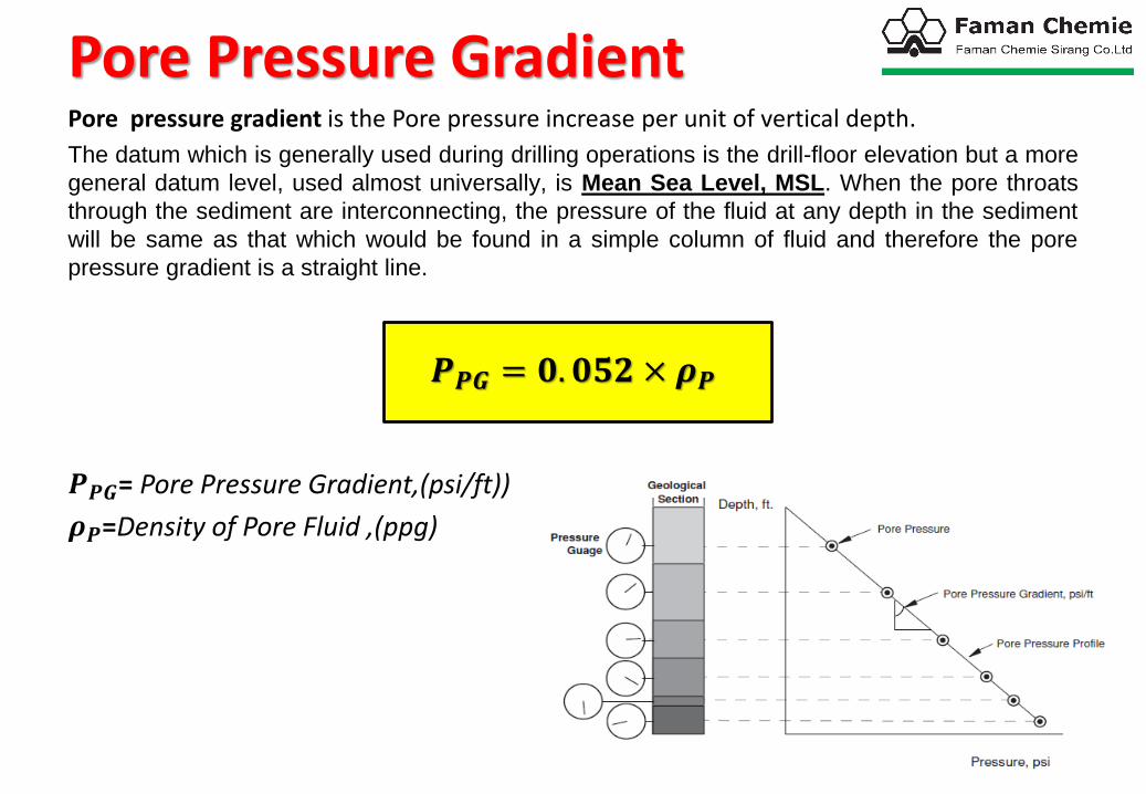
Pore Pressure GradientPore pressure gradient is the Pore pressure increase per unit of vertical depth.
The datum which is generally used during drilling operations is the drill-floor elevation but a more
general datum level, used almost universally, is Mean Sea Level, MSL. When the pore throats
through the sediment are interconnecting, the pressure of the fluid at any depth in the sediment
will be same as that which would be found in a simple column of fluid and therefore the pore
pressure gradient is a straight line.
𝑷𝑷𝑮 = 𝟎. 𝟎𝟓𝟐 × 𝝆𝑷
𝑷𝑷𝑮= Pore Pressure Gradient,(psi/ft))
𝝆𝑷=Density of Pore Fluid ,(ppg)


PorosityThe percentage of pore volume or void space, or that volume within rock that can contain fluids. Porosity can be a relic of deposition (primary porosity, such as space between grains that were not compacted together completely) or can develop through alteration of the rock (secondary porosity, such as when feldspar grains or fossils are preferentially dissolved from sandstones). Porosity can be generated by the development of fractures, in which case it is called fracture porosity.
∅ =𝑽𝒗𝑽
=𝝆𝒎 − 𝝆𝒃𝝆𝒎 − 𝝆𝒇
∅ =Porosity
𝑽 =Bulk Volume
𝑽𝒗 =Pore volume
𝝆𝒎 =Matrix density
𝝆𝒃 =Bulk Density
𝝆𝒇 =Pore fluid density
𝟏 > ∅ > 𝟎

PermeabilityThe ability, or measurement of a rock's ability, to transmit fluids, typically measured in darciesor millidarcies. The term was basically defined by Henry Darcy, who showed that the common mathematics of heat transfer could be modified to adequately describe fluid flow in porous media. Formations that transmit fluids readily, such as sandstones, are described as permeable and tend to have many large, well-connected pores. Impermeable formations, such as shales and siltstones, tend to be finer grained or of a mixed grain size, with smaller, fewer, or less interconnected pores.
𝒌 = 𝑨𝑸
𝝁
∆𝑷
𝑳
𝒌 =Permeability
𝑸=Rate of flow
𝝁=Fluid viscosity


Overburden PressureThe vertical pressure at any point in the earth is known as the overburden pressure. Theoverburden pressure is defined as the pressure exerted by the total weight ofoverlyingformations above the point of interest. The total weight is the combined weight ofboth theformation solids (rock matrix) and formation fluids in the pore space.
𝝈𝒐𝒃=Overburden pressure(psi)
𝝆𝒃=Formation bulk density (sediment plus fluid)( ΤIb gal)
𝝈𝒐𝒈=Overburden gradient( Τpsi ft)
𝑻𝑽𝑫=True Vertical Depth(ft)
𝑷𝑶 = 𝟎. 𝟎𝟓𝟐 × 𝝆𝒃 × 𝑻𝑽𝑫
𝑷𝑶𝑮 = 𝟎. 𝟎𝟓𝟐 × 𝝆𝒃

A useful equation for calculating the formation bulk density (density of sediment plus fluid) under field conditions of varying lithological and pore fluid density is given by:
𝝆𝒃 = 𝝆𝒎 − (𝝆𝒎 − 𝝆𝑷)∅
𝝆𝒃=Formation bulk density
𝝆𝒎=Matrix Density
∅=Porosity (Fractional)
𝝆𝑷=formation fluid density

Total overburden pressure is supported by the rock in two ways. The first is throughintergranular pressure 𝝈𝒛, a matrix stress caused by the force transmitted throughgrain-to-grain mechanical contact. As formations are compacted by the overburdenwith increasing burial depth, pore fluid escapes so that pore pressure 𝑷𝒇is equal to
the hydrostatic pressure of the pore fluid density.
𝑷𝑶 = 𝑷𝑷 + 𝝈𝒛
𝝈𝒐𝒃= Overburden pressure
𝑷𝒇= Pore Pressure
𝝈𝒛 =Matrix stress𝝈𝒐𝒃
𝑷𝒇 𝝈𝒛
𝑷𝒇
𝝈𝒛

𝑷𝑶 = 𝑷𝑷 + 𝝈𝒛𝝈𝒐𝒃= Overburden pressure𝑷𝒇= Pore Pressure
𝝈𝒛= Matrix stress

Since sediment bulk densities vary with location and depth due to compaction, bulk density isusually taken as 144 lb/ft3 (19.25 lb/gal or SG 2.3) so the geostatic or overburden gradient is1 psi/ft (0.23 kg/cm2/m). The average geostatic gradient plotted against depth for the Gulf ofMexico is closer to 0.83 psi/ft (~16 lb/gal) near the surface and 1.0 psi/ft (~20 lb/gal) near20,000 ft. If the overburden gradient is not known, assume that it is 1.0 psi/ft, or use thenearest offset known value.

CompactionCompaction is the reduction of the sediment bulk volume and is equivalent to volumetric strain:
𝝐𝒗 =𝑽
𝑽𝟎𝑽 =load bearing volume
𝑽𝟎 =unloaded initial volume

Compacting Theory
• Compaction is caused by overburden load, thus sediments are compacted more with increasing burial depth.
• Compaction mainly decreases porosity, but also reduces the grain volume. Generally, the rock and pore volumes are reduced with reversible (elastic) and irreversible (plastic) contributions

• Hydrostatic equilibrium within the compacted layers is retained as long as the expelled water
• If the expelled water is not free to escape, abnormal pressures may result. Sufficient compaction cannot occur so the pore fluids carry more of the overburden

Abnormal PressureA “normally” pressured formation has a pore pressure equal to the hydrostaticpressure of the pore water.Any deviation from the normal hydrostatic pressureenvironment is referred to as abnormal. High pressures are called geopressures,overpressures or sur-pressures. Low pressures are called underpressures orsubpressures.
Pore Pressure
Normal Pressure
Underpressure(Sur-Pressure)
Overpressure(Sub-Pressure)

Normal PressureA “normally” pressured formation has a pore pressure equal to the hydrostatic pressure of the pore water. Since many more wells are drilled in sediments characterized by 8.95-lb/gal saltwater, a “normal” pressure gradient, for the purposes of this discussion, is considered to be 0.465 psi/ft.
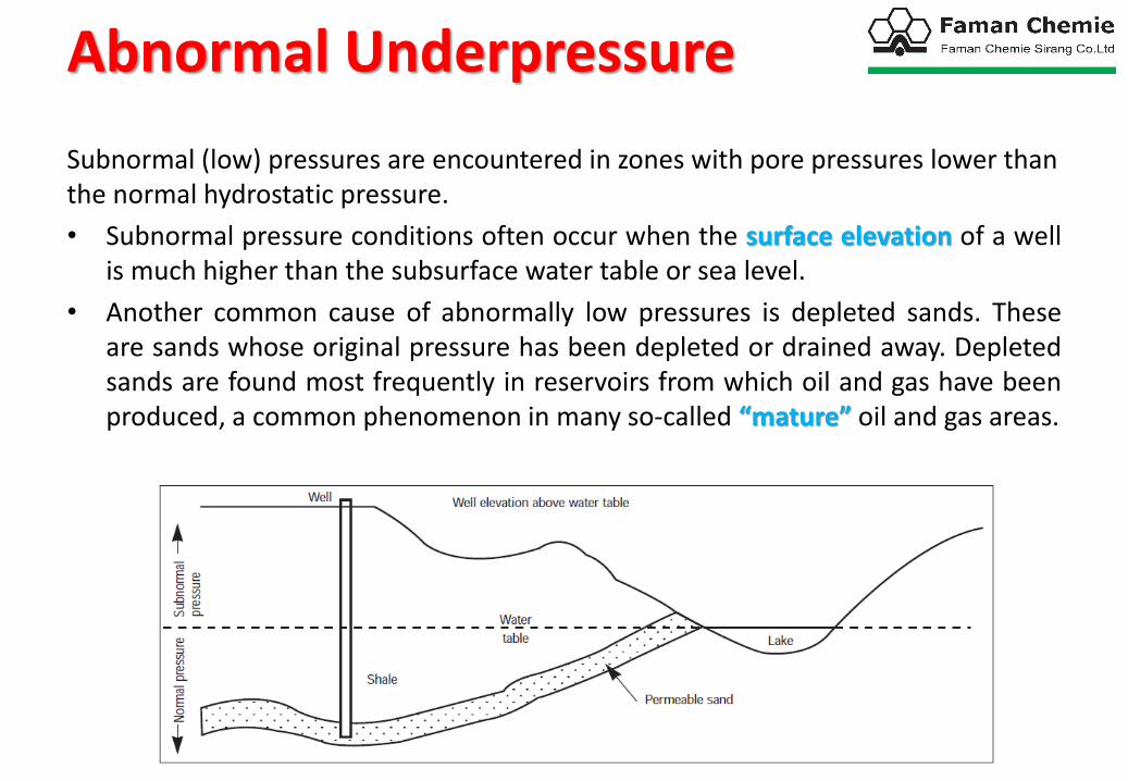
Subnormal (low) pressures are encountered in zones with pore pressures lower than the normal hydrostatic pressure.
• Subnormal pressure conditions often occur when the surface elevation of a wellis much higher than the subsurface water table or sea level.
• Another common cause of abnormally low pressures is depleted sands. Theseare sands whose original pressure has been depleted or drained away. Depletedsands are found most frequently in reservoirs from which oil and gas have beenproduced, a common phenomenon in many so-called “mature” oil and gas areas.
Abnormal Underpressure

Abnormal OverpressureAbnormal Overpressure characterize those zones that have pore pressures higher than the normal hydrostatic pressure of the pore fluids .Abnormal Overpressure are created and maintained by the restriction of pore fluid movement. Abnormal overpressures are always caused by a particular zone becoming “sealed” or isolated. Seals are impermeable layers and boundary zones that will not permit the release of pressure generated by the percolation of fluids and gases to higher zones and subsequently to the surface.
The zone between the normally pressured zone and the overpressured zone is known as the transition zone. The pressures in both the transition and overpressured zone is quite clearly above the hydrostatic pressure gradient line. The transition zone is therefore the seal or caprock on the overpressured formation.

The compaction process can be described by a simplified model consisting of a vessel containing a fluid (representing the pore fluid) and a spring (representing the rock matrix). The overburden stress can be simulated by a piston being forced down on the vessel. The overburden (S) is supported by the stress in the spring (σ) and the fluid pressure (p). If the overburden is increased (e.g. due to more sediments being laid down) the extra load must be borne by the matrix and the pore fluid. If the fluid is prevented from leaving the pore space (drainage path closed) the fluid pressure must increase above the hydrostatic value. Such a formation can be described as overpressured (i.e. part of the overburden stress is being supported by the fluid in the pore spaceand not the matrix). Since the water is effectively incompressible the overburden is almost totally supported by the pore fluid and the grain to grain contact stress is not increased. In a
formation where the fluids are free to move (drainage path open), the increased load must be taken by the matrix, while the fluid pressure remains constant. Under such circumstances the pore pressure can be described as Normal, and is proportional to depth and fluid density.

Origin of Overpressured Formations

1-UndercompactionIn a normally pressured environment, sedimentsare compacted as the increasing weight of theoverburden squeezes out the connate water.Thus, the porosity (void space) decreases withdepth.
In the most common scenario, a seal hasformed,trapping pore water so that compaction(due to increasing overburden with depth) doesnot occur as in a normally pressuredenvironment. When the sediments are notcompacted enough to form grain-to-graincontact, the overburden is supported in part bythe pore pressure, causing abnormally high porepressure Under abnormal conditions, the wateris not allowed to escape, and the compactingprocess is altered. The porosity no longercontinues to decrease and, In most cases, willincrease below the top of the geopressuredzone.

2-UpliftOne cause of geopressure is the geologic uplifting displacement of a formation, which physically places a higher-pressured formation from a greater depth to a shallower depth. When a previously normal pressure zone at great depth is displaced by tectonic actions to a shallower depth with the seals remaining intact, the resulting pressure gradient will be abnormally high.

3-Salt DiaparismDiapirism is the piercement of a formation by a plastic, mobile, less dense underlying formation, typically salt. Salt exhibits plastic behaviour at elevated temperatures and pressures and due to its low density will move upwards to form salt domes in overlying formations. The creation of the salt dome can lead to abnormal pressure development in surrounding formations in two ways: Firstly, the movement of the salt creates additional tectonic stresses within the overlying sediments whilst at the same time providing a lateral seal limiting pore water expulsion. These tectonic stresses usually create folding and faulting in the surrounding zones.Secondly the salt may encapsulate rafters of overlying formations (usually limestones and dolomites) as it flows upwards, trapping pressures within the
rafters. In this instance the salt prohibits further de-watering of the rafter and abnormal pressure will develop.

4-Massive Shale(Clay Diagenesis)
The diagenetic changes which occur in shales are one of the most important mechanisms by which abnormal pressure may be generated in a marine environment. On initial burial, marine clays are composed of predominantly smectite clays of which montmorillonite is by far the most common. Montmorillonite has a swelling lattice and contains approximately 70-85% water during initial deposition. The water is held as interlayer water between the clay platelets and also as free pore water. This environment is usually alkaline in nature and is rich in calcium and magnesium ions but poor in potassium ions. Upon further burial, compaction expels most of the free pore water and the water content is thus reduced to approximately 30%. With further burial, there will be increases in both the overburden
load and temperature and these two effects cause all but the last layer of structural water to be expelled to the pore space.

This causes the clay lattice to collapse and in the presence of potassium ions, montmorillonite diagenesis to illite occurs.If the water released in this process cannot escape during compaction, then the pore fluid will support an increased portion of the overburden and will thus be abnormally pressured.

5- Diagenesis of Sulphate Formations
The conversion of gypsum (𝐶𝑎𝑆𝑂4 • 2𝐻2𝑂) to anhydrite (𝐶𝑎𝑆𝑂4),an extremely impermeable evaporate expels water with increasing depth (pressure and temperature) resulting an abnormally pressured sediments below them.
𝑪𝒂𝑺𝑶𝟒 • 𝟐𝑯𝟐𝑶𝒑𝒓𝒆𝒔𝒔𝒖𝒓𝒆 𝒂𝒏𝒅 𝑯𝒆𝒂𝒕
𝑪𝒂𝑺𝑶𝟒 + 𝟐𝑯𝟐𝑶

Formation Fracture Pressure
Formation Fracture Pressure
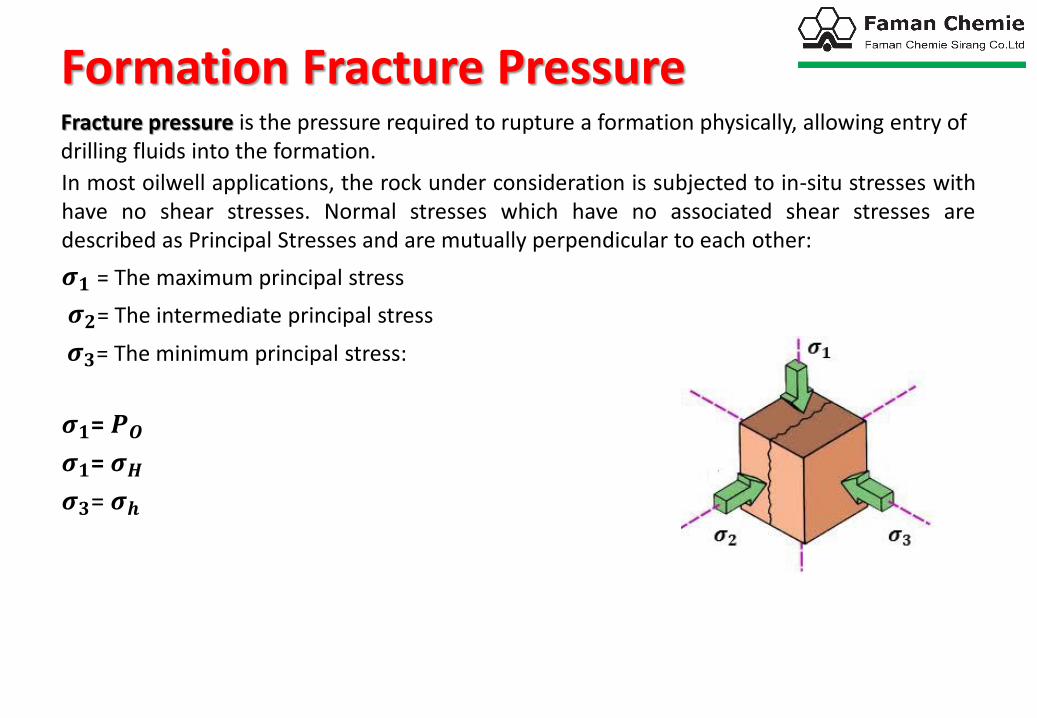
In most oilwell applications, the rock under consideration is subjected to in-situ stresses with have no shear stresses. Normal stresses which have no associated shear stresses are described as Principal Stresses and are mutually perpendicular to each other:
𝝈𝟏 = The maximum principal stress
𝝈𝟐= The intermediate principal stress
𝝈𝟑= The minimum principal stress:
𝝈𝟏= 𝑷𝑶
𝝈𝟏= 𝝈𝑯𝝈𝟑= 𝝈𝒉
Fracture pressure is the pressure required to rupture a formation physically, allowing entry of drilling fluids into the formation.

In most cases the maximum principal stress will be vertical due to the pressure of the overlying rock. This is defined as the overburden pressure.
In a tectonically stable basin, the maximum principal stress will be vertical and the horizontal stresses will be equal.
𝝈𝟏= 𝑷𝑶
𝝈𝟏= 𝝈𝟑In any area undergoing tectonic activity the horizontal stresses are distorted creating an intermediate and a minimum principal stress. The three stresses are: vertical stress (overburden, 𝑷𝑶) is the maximum stress and the intermediate horizontal stress 𝝈𝑯 and the minimum horizontal stress 𝝈𝒉 is normal to 𝝈𝑯
𝝈𝟏= 𝑷𝑶
𝝈𝟏= 𝝈𝑯𝝈𝟑= 𝝈𝒉
In areas of high tectonic activities such as mountain belts, the maximum principal stress may be horizontal and the minimum principal stress is vertical.

Fracture of the formation results when the pressure in the wellbore is equal to, or greater, than the minimum principal stress (assuming the tensile strength of rock is negligible). The fracture will propagate along the path of least resistance which is perpendicular to the direction of the minimum principal stress. Thus fractures will be vertical in areas where the minimum principal stress is horizontal, and horizontal where the minimum principal stress is vertical.

Estimating Fracture PressureHubbert and Willis:
Under normal hydrostatic conditions:
𝑷𝑶𝑮 ≈ 𝟏 𝒑𝒔𝒊/𝒇𝒕
𝑷𝑷𝑮 ≈ 𝟎. 𝟒𝟔𝟓 Τ𝒑𝒔𝒊 𝒇𝒕
Then:
𝑷𝑭𝑮 = 𝟎. 𝟔𝟒 𝒑𝒔𝒊/𝒇𝒕
𝑷𝑭 =(𝑷𝑶 − 𝑷𝑷)
𝟑+ 𝑷𝑷
𝑷𝑭𝑮 ≈(𝑷𝑶𝑮 − 𝟐𝑷𝑷𝑮)
𝟑

Matthews & Kelly:
𝑷𝑭𝑮 = 𝑷𝑷𝑮 +𝑲𝒊 𝑷𝑶𝑮 − 𝑷𝑷𝑮
𝑷𝑭𝑮 = 𝑷𝑷𝑮 +𝑲𝒊 𝝈𝒛
𝑲𝒊 =matrix-stress coefficient

Ben Eaton:
𝑷𝑭𝑮 = 𝑷𝑶𝑮 − 𝑷𝑷𝑮
𝒗
𝟏 − 𝒗+ 𝑷𝑷𝑮
𝒗= Poisson’s ratio of the rock

Measuring Fracture Pressure
Many problems exist in trying to estimate fracture pressures. This is because the exact values of the components that contribute to formation strength are not known. These factors are local.Data from one area cannot be readily applied to other areas.
The fracture pressure estimate is used to help design a drilling program for a well with regard to casing depths and hole sizes. Once a well has spudded,the formation fracture pressure should be determined by physical tests.
Two tests are used to measure the formation strength or fracture pressure.These are: (1) the Leak-Off Test (LOT) and (2) the Formation-Integrity Test (FIT). These tests are conducted after casing has been set and the casing shoe has been drilled out. Although procedures differ from one operator to the other, a common practice is to drill either to the first sand or 10 ft of new formation before running either test. In some cases, the test can be run again after drilling further. This is usually done when mud weights are used that exceed those planned for in the well plan or mud program.
Leak-off tests and formation-integrity tests are very similar. The difference is that the leak-off test fractures the formation and measures the actual strength of the formation, while the formation integrity test measures the formation to a predetermined pressure but does not cause a fracture. The formation being drilled often determines which of them will be used. The formation integrity test is used more often in hard-rock formations than the leak-off test.

Leak Off Test (LOT)1. Drill out the casing shoe and sufficient new formation.
2. Circulate the drilling fluid to ensure a consistent mud weight.
3. Stop the rig pumps and shut the well in.
4. Pump mud into the shut-in well at a very low rate. A typical pump rate of 0.25 to 0.5barrels per minute (bbl/min) is used. Normally, a cementing unit is used so an accurate reading of volume and pressure can be obtained.
5. Record the pressure and volume pumped. A graphical presentation should be made of these data to determine the point at which the fluid is being pumped into the formation (leak-off). A normal leak-off test will show the pressure increasing in a straight line with the volume of mud pumped. Once the fracture pressure is reached, the pressure will stop increasing with volume pumped as the
fracture is being propagated. The pressure may actually decrease as fluid is pumped into the formation. is an illustration of a graph obtained from a leak-off test.

6. Once leak-off has been observed ,stop pumping and observe the well . The pressure should remain relatively the same or decrease slightly once pumping has stopped.
7. Record the pressure where the fluid started leaking off into the formation . Convert this pressure to a mud weight equivalent by using the following equation.
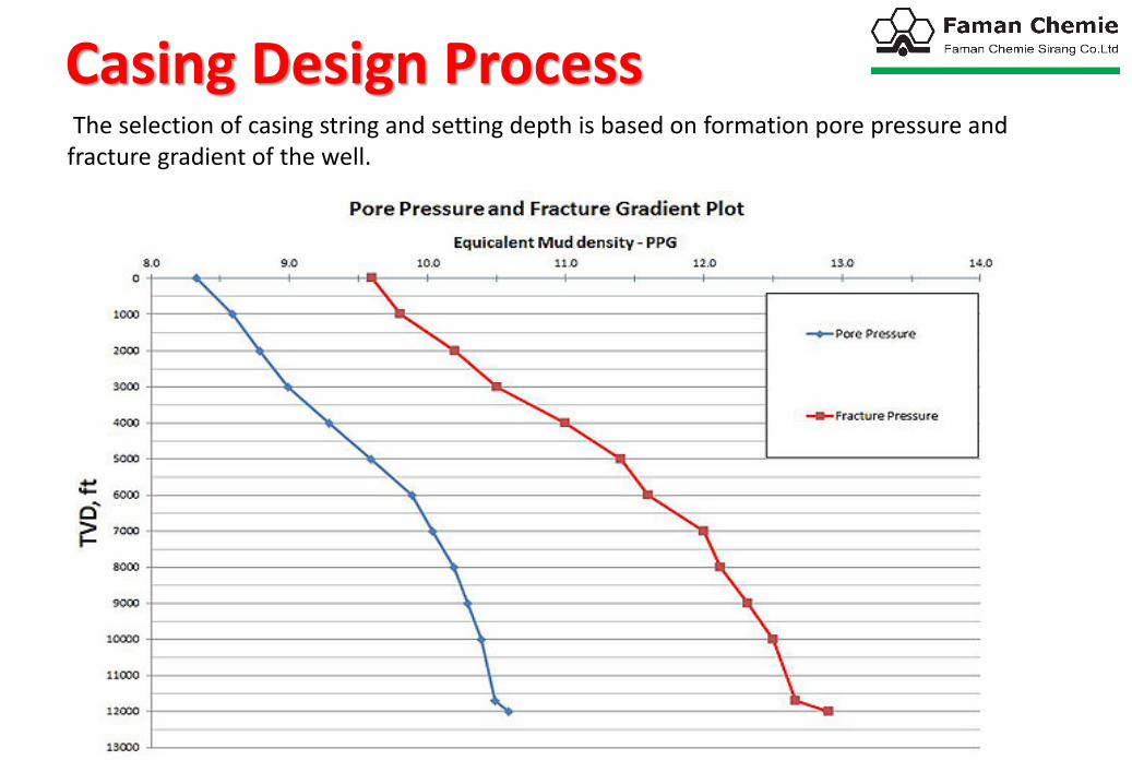
Casing Design ProcessThe selection of casing string and setting depth is based on formation pore pressure and
fracture gradient of the well.

The solid lines in the chart are not accounted for safety factor; therefore, for the first step of casing seat design, safety margin must be applied. For this example, we will add 0.3 ppg for safety for both pore pressure and fracture gradient (Figure 2). You need to add the safety factor into formation pressure and subtract it from the fracture gradient. What’s more, the safety factor value may depends on where you work and how much confident in your data.

Top Down Casing Design
This design will start from the surface of the well down to the bottom and the setting depths are designed within the safety factor limits (dotted lines). We start by drawing the vertical line from the facture gradient dashed line (point A) down to pore pressure dashed line (point B). See Figure 7. The first casing should be set from surface to 3,000’ TVD.

Next, draw the horizontal line from Point B to Point C located in the fracture dashed line curve. Then draw the vertical line from Point C to intersect the formation pressure dashed line curve at Point D. This is the section casing string which should be set from 3,000’ TVD to 6,000’ TVD.

Applying the same concept to the next string, draw the horizontal line from Point D to intersect thefracture gradient with safety factor chart at Point E and draw the vertical line from Point E to the targetdepth at Point F. The last casing string should be set from 6,000’ TVD to 12,000’ TVD.
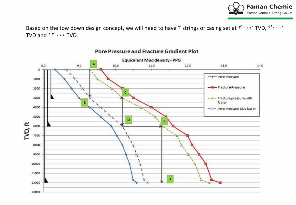
Based on the tow down design concept, we will need to have 3 strings of casing set at 3,000’ TVD, 6,000’ TVD and 12,000 TVD.

Bottom Up Casing DesignThis design will start from the bottom of the well up to surface and the setting depths are designed within the safety factor limits (dotted lines). Starting at the bottom (formation pressure dashed line – Point A), draw a vertical line upward to fracture pressure dashed line – Point B (Figure 3). Casing should be set from 4,500’ TVD to 12,000’ TVD because you can reach TD (12,000’ TVD) with highest equivalent mud weight and you will not break the formation at shallow depth (4,500 TVD). We will apply this same concept to another string

The next casing string is determined by drawing a horizontal line from Point B to intersect the pore pressure dashed line at Point C. Then draw a vertical line from Point C to the fracture gradient dashed line at Point D (Figure 4). The Casing must be set from 1,800’ TVD to 4,500’ TVD.

With the same idea, the next casing string is determined by drawing a horizontal line from Point D to Point E and a vertical line from Point E to Point F (Figure 5). The Casing must be set from surface to 1,800’ TVD.

Based on the bottom up design concept, we will need to have 3 strings of casing set at 1800’ TVD, 4500’ TVD and 12,000 TVD .