forming and welding line for radio frequency … rf gb 0401_1.pdfforming and welding line for radio...
TRANSCRIPT
Forming and Welding Linefor Radio Frequency Cables
UNIWEMA® RF
2
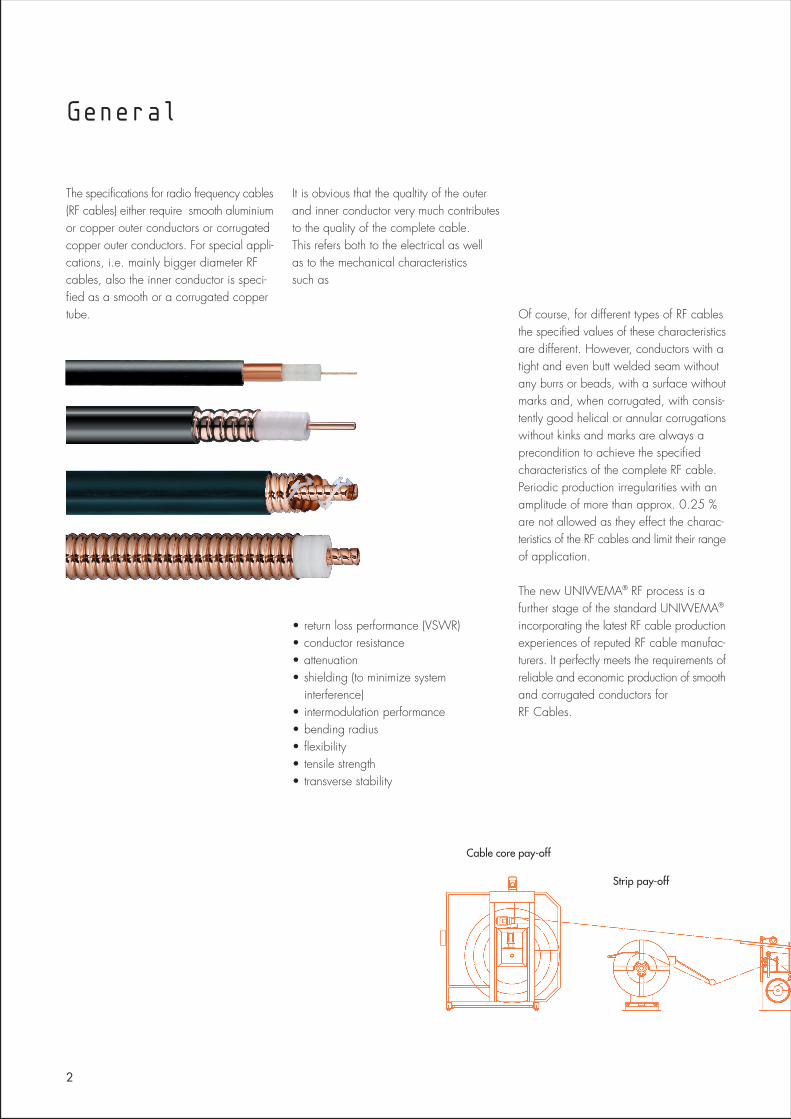
The specifications for radio frequency cables(RF cables) either require smooth aluminiumor copper outer conductors or corrugatedcopper outer conductors. For special appli-cations, i.e. mainly bigger diameter RFcables, also the inner conductor is speci-fied as a smooth or a corrugated coppertube.
It is obvious that the qualtity of the outerand inner conductor very much contributesto the quality of the complete cable.This refers both to the electrical as wellas to the mechanical characteristicssuch as
• return loss performance (VSWR)• conductor resistance• attenuation• shielding (to minimize system
interference)• intermodulation performance• bending radius• flexibility• tensile strength• transverse stability
Of course, for different types of RF cablesthe specified values of these characteristicsare different. However, conductors with atight and even butt welded seam withoutany burrs or beads, with a surface withoutmarks and, when corrugated, with consis-tently good helical or annular corrugationswithout kinks and marks are always aprecondition to achieve the specifiedcharacteristics of the complete RF cable.Periodic production irregularities with anamplitude of more than approx. 0.25 %are not allowed as they effect the charac-teristics of the RF cables and limit their rangeof application.
The new UNIWEMA® RF process is afurther stage of the standard UNIWEMA®
incorporating the latest RF cable productionexperiences of reputed RF cable manufac-turers. It perfectly meets the requirements ofreliable and economic production of smoothand corrugated conductors forRF Cables.
General
Strip pay-off
Cable core pay-off
The UNIWEMA® process is designed toproduce from a metal strip a welded smoothor corrugated tube. In this process, a metalstrip is introduced into the machine and, ina single operation, the strip edges aretrimmed, the strip is placed around a cablecore and formed into a tube. The opposingstrip edges are butt welded. A special belttype caterpillar capstan located downstreamfrom the welding station pulls the tubetogether with the cable core through themachine and, if added flexibility is desired,transports it to the corrugator. The perfectcoordination of the forming and weldingoperations with the special caterpillarcapstan is a pre-condition for obtaining auniform welded seam, thus ensuring optimumproduct quality. The design and the material of the severalstages of the tube forming station are dic-tated by the characteristics of the metal strip,its wall thickness and the diameter of thewelded tube. A precondition for obtaininga good welding seam is the accuratepositioning of the strip edges at the weldingpoint. They must exactly meet each otherwith a minimum gap.
With the TIG (tungsten inert gas) weldingmethod the two strip edges are molten andwelded together by an electric arc.The concentrated heat effect of the arcproduces a narrow weld area whereby the
welding heat is quickly dissipated alongthe tube surface. The formation of an oxidelayer in the weld area is prevented by aprotective gas layer. A constant weldingcurrent is required to obtain a uniform goodquality of the welded seam. This isaccomplished by power transistorsincorporated in the welding current source.A current rise control (“Startomatic”) adjuststhe welding current automatically to themanufacturing speed. The set welding currentvs. manufacturing speed relationship for agiven tube or cable sheath can be storedin a computer and retrieved whenever anidentical product is to be produced. Restartof the welding operation without any burn-throughs is possible after an intermediatestop.
The standard UNIWEMA® is equipped witha single electrode. In applications wherethe maximum allowable welding currentwith one electrode is insufficient for thewelding of heavier strip walls or if higherspeeds are desired the UNIWEMA® canalso be operated with a 3-electrode weldingtorch (Polyarc welder). For a continuousoperation a 2-electrode welding torch(TwinTorch) can be utilized.As a further development of the UNIWEMA®
process we have added a LASER weldingalternative which is particularly suited forthe welding of thin metallic strips, particularlyfor small tube sizes.The belt type caterpillar capstan is anessential component of all UNIWEMA® RF
machines. It pulls the tube through thedifferent stations of the UNIWEMA®
machine. Especially for RF cable productionthe caterpillar capstan shall not leave anymark or impression on the welded tubewhile it has to absorb all torsion forcesexerted onto the tube in the subsequentcorrugation process. The speed variations,especially the periodical speed variations,have to be better than 0.25 %. For a uniformweld seam and thus for an optimum productquality, the perfect coordination of formingtools, welding equipment and caterpillarcapstan is an important precondition.The UNIWEMA® RF belt type caterpillarcapstan ensures this performance charac-teristics.The caterpillar capstan moves the weldedtube to the corrugation unit. A freely rotatingcorrugating ring which can be adjusted inradial direction and in its angle impartscorrugations to the tube whereby pitch andcorrugation depth can be regulated. Thecorrugated tube grips the cable core tightly.Through the choice of a suitable corrugationtool helical or annular corrugations can beproduced.
The UNIWEMA® Process
3
UNIWEMA® RF
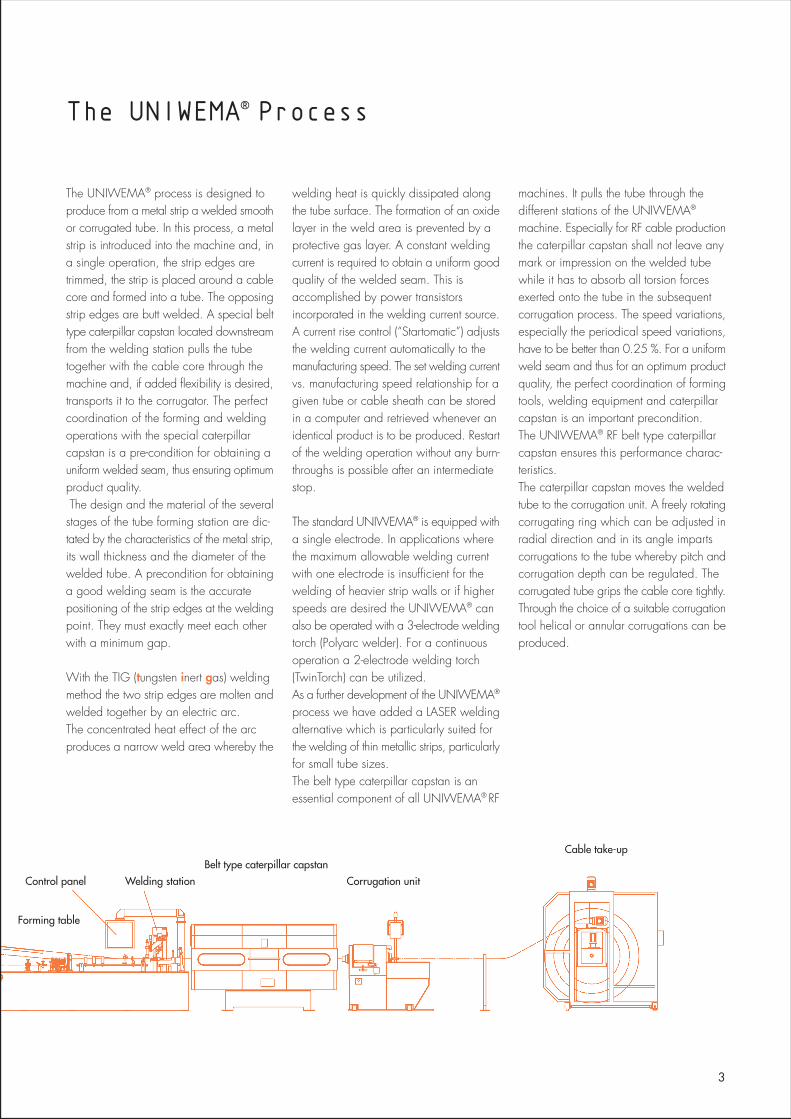
Forming table
Control panel Welding stationBelt type caterpillar capstan
Corrugation unit
Cable take-up
Several types of UNIWEMA® machinesare available, ensuring optimal productionconditions for a specific diameter range.
OverviewThe machine consists of the following majorsub-units:
• Cable core pay-off• Strip pay-off• Forming table• Welding station• Belt type caterpillar capstan• Corrugation unit• Cable take-up• Electrical equipment• Accessories for continuous
production
Cable core pay-offDifferent types of cable core pay-offs canbe installed in-line with the UNIWEMA®.We do recommend traversing portal pay-offs which are synchronized with the linespeed via dancer.
Strip pay-offThe design of the strip pay-off depends onthe packaging of the metal strip supply.
For synchronization with the followingproduction stages the pay-off stands aremotor driven and dancer arm controlled. Itcan be supplied with a number of desiredaccessories, e.g. with horizontal shiftingand vertical lift unit.
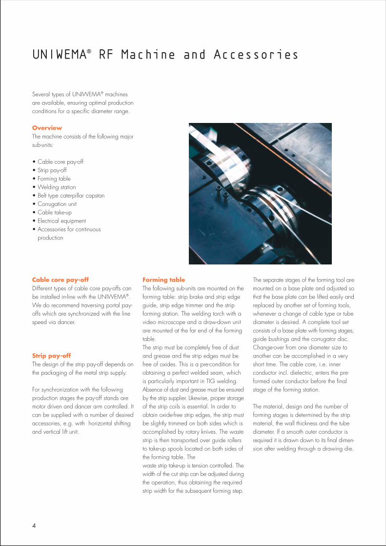
Forming tableThe following sub-units are mounted on theforming table: strip brake and strip edgeguide, strip edge trimmer and the stripforming station. The welding torch with avideo microscope and a draw-down unitare mounted at the far end of the formingtable.The strip must be completely free of dustand grease and the strip edges must befree of oxides. This is a pre-condition forobtaining a perfect welded seam, whichis particularly important in TIG welding.Absence of dust and grease must be ensuredby the strip supplier. Likewise, proper storageof the strip coils is essential. In order toobtain oxide-free strip edges, the strip mustbe slightly trimmed on both sides which isaccomplished by rotary knives. The wastestrip is then transported over guide rollersto take-up spools located on both sides ofthe forming table. Thewaste strip take-up is tension controlled. Thewidth of the cut strip can be adjusted duringthe operation, thus obtaining the requiredstrip width for the subsequent forming step.
The separate stages of the forming tool aremounted on a base plate and adjusted sothat the base plate can be lifted easily andreplaced by another set of forming tools,whenever a change of cable type or tubediameter is desired. A complete tool setconsists of a base plate with forming stages,guide bushings and the corrugator disc.Change-over from one diameter size toanother can be accomplished in a veryshort time. The cable core, i.e. innerconductor incl. dielectric, enters the pre-formed outer conductor before the finalstage of the forming station.
The material, design and the number offorming stages is determined by the stripmaterial, the wall thickness and the tubediameter. If a smooth outer conductor isrequired it is drawn down to its final dimen-sion after welding through a drawing die.
UNIWEMA® RF Machine and Accessories
4
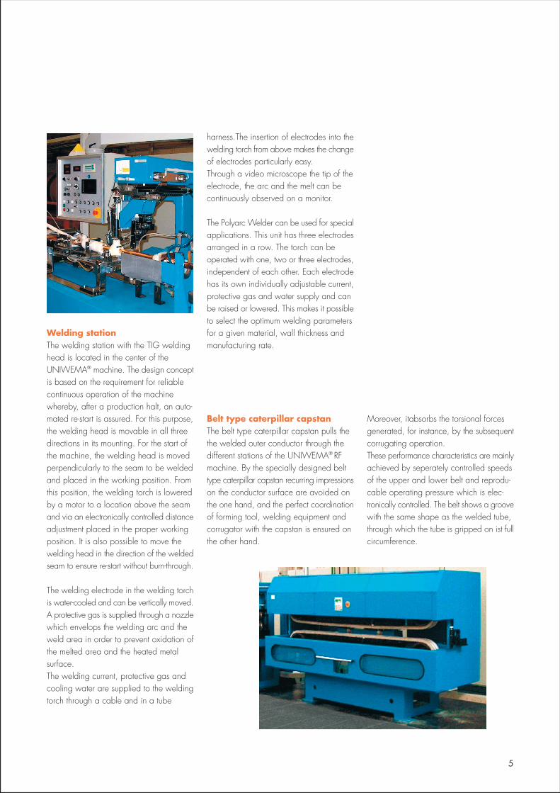
Welding stationThe welding station with the TIG weldinghead is located in the center of theUNIWEMA® machine. The design conceptis based on the requirement for reliablecontinuous operation of the machinewhereby, after a production halt, an auto-mated re-start is assured. For this purpose,the welding head is movable in all threedirections in its mounting. For the start ofthe machine, the welding head is movedperpendicularly to the seam to be weldedand placed in the working position. Fromthis position, the welding torch is loweredby a motor to a location above the seamand via an electronically controlled distanceadjustment placed in the proper workingposition. It is also possible to move thewelding head in the direction of the weldedseam to ensure re-start without burn-through.
The welding electrode in the welding torchis water-cooled and can be vertically moved.A protective gas is supplied through a nozzlewhich envelops the welding arc and theweld area in order to prevent oxidation ofthe melted area and the heated metalsurface.The welding current, protective gas andcooling water are supplied to the weldingtorch through a cable and in a tube
harness.The insertion of electrodes into thewelding torch from above makes the changeof electrodes particularly easy.Through a video microscope the tip of theelectrode, the arc and the melt can becontinuously observed on a monitor.
The Polyarc Welder can be used for specialapplications. This unit has three electrodesarranged in a row. The torch can beoperated with one, two or three electrodes,independent of each other. Each electrodehas its own individually adjustable current,protective gas and water supply and canbe raised or lowered. This makes it possibleto select the optimum welding parametersfor a given material, wall thickness andmanufacturing rate.
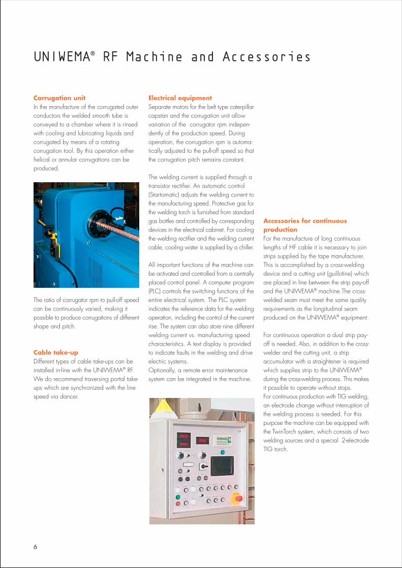
Belt type caterpillar capstanThe belt type caterpillar capstan pulls thethe welded outer conductor through thedifferent stations of the UNIWEMA® RFmachine. By the specially designed belttype caterpillar capstan recurring impressionson the conductor surface are avoided onthe one hand, and the perfect coordinationof forming tool, welding equipment andcorrugator with the capstan is ensured onthe other hand.
Moreover, itabsorbs the torsional forcesgenerated, for instance, by the subsequentcorrugating operation.These performance characteristics are mainlyachieved by seperately controlled speedsof the upper and lower belt and reprodu-cable operating pressure which is elec-tronically controlled. The belt shows a groovewith the same shape as the welded tube,through which the tube is gripped on ist fullcircumference.
5
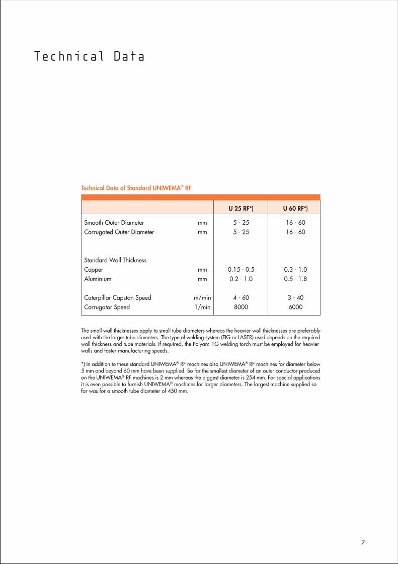
Corrugation unitIn the manufacture of the corrugated outerconductors the welded smooth tube isconveyed to a chamber where it is rinsedwith cooling and lubricating liquids andcorrugated by means of a rotatingcorrugation tool. By this operation eitherhelical or annular corrugations can beproduced.
The ratio of corrugator rpm to pull-off speedcan be continuously varied, making itpossible to produce corrugations of differentshape and pitch.
Cable take-upDifferent types of cable take-ups can beinstalled in-line with the UNIWEMA® RF.We do recommend traversing portal take-ups which are synchronized with the linespeed via dancer.
Electrical equipmentSeparate motors for the belt type caterpillarcapstan and the corrugation unit allowvariation of the corrugator rpm indepen-dently of the production speed. Duringoperation, the corrugation rpm is automa-tically adjusted to the pull-off speed so thatthe corrugation pitch remains constant.
The welding current is supplied through atransistor rectifier. An automatic control(Startomatic) adjusts the welding current tothe manufacturing speed. Protective gas forthe welding torch is furnished from standardgas bottles and controlled by correspondingdevices in the electrical cabinet. For coolingthe welding rectifier and the welding currentcable, cooling water is supplied by a chiller.
All important functions of the machine canbe activated and controlled from a centrallyplaced control panel. A computer program(PLC) controls the switching functions of theentire electrical system. The PLC systemindicates the reference data for the weldingoperation, including the control of the currentrise. The system can also store nine differentwelding current vs. manufacturing speedcharacteristics. A text display is providedto indicate faults in the welding and driveelectric systems.Optionally, a remote error maintenancesystem can be integrated in the machine.
Accessories for continuousproductionFor the manufacture of long continuouslengths of HF cable it is necessary to joinstrips supplied by the tape manufacturer.This is accomplished by a cross-weldingdevice and a cutting unit (guillotine) whichare placed in line between the strip pay-offand the UNIWEMA® machine.The cross-welded seam must meet the same qualityrequirements as the longitudinal seamproduced on the UNIWEMA® equipment.
For continuous operation a dual strip pay-off is needed. Also, in addition to the cross-welder and the cutting unit, a stripaccumulator with a straightener is requiredwhich supplies strip to the UNIWEMA®
during the cross-welding process. This makesit possible to operate without stops.For continuous production with TIG welding,an electrode change without interruption ofthe welding process is needed. For thispurpose the machine can be equipped withthe TwinTorch system, which consists of twowelding sources and a special 2-electrodeTIG torch.
UNIWEMA® RF Machine and Accessories
6
The small wall thicknesses apply to small tube diameters whereas the heavier wall thicknesses are preferablyused with the larger tube diameters. The type of welding system (TIG or LASER) used depends on the requiredwall thickness and tube materials. If required, the Polyarc TIG welding torch must be employed for heavierwalls and faster manufacturing speeds.
*) In addition to these standard UNIWEMA® RF machines also UNIWEMA® RF machines for diameter below5 mm and beyond 60 mm have been supplied. So far the smallest diameter of an outer conductor producedon the UNIWEMA® RF machines is 2 mm whereas the biggest diameter is 254 mm. For special applicationsit is even possible to furnish UNIWEMA® machines for larger diameters. The largest machine supplied sofar was for a smooth tube diameter of 450 mm.
7
Technical Data
U 25 RF*) U 60 RF*)
Smooth Outer Diameter mm 5 - 25 16 - 60Corrugated Outer Diameter mm 5 - 25 16 - 60
Standard Wall ThicknessCopper mm 0.15 - 0.5 0.3 - 1.0Aluminium mm 0.2 - 1.0 0.5 - 1.8
Caterpillar Capstan Speed m/min 4 - 60 3 - 40Corrugator Speed 1/min 8000 6000
Technical Data of Standard UNIWEMA® RF
Janu
ar 2
004
- Cop
yrig
ht ©
200
4 - N
exan
s - (
0104
.003
.08)
(844
10
010)
Nexans Deutschland Industries GmbH & Co. KG · Production Lines and TechnologyKabelkamp 20 · 30179 Hannover · Germany
Phone +49 511 676-2321 · Fax +49 511 676-3777eMail: [email protected] · www.nexans.de
Global expert in cables and cabling systems