formula tables in solid mechanics - division of solid ... · 1 formula tables in solid mechanics...
TRANSCRIPT

1
FORMULA TABLES IN SOLID MECHANICS
Compiled by Sören Sjöström. Latest update 6th December, 2013.
Contents
Elementary beam bending cases
Data for some frequent cross-section geometries
Beam with axial load
Euler instability cases
Westergaard solution for stress and displacement near a crack tip
Stress-intensity factors for some elementary crack cases
Energy release rate
Mixed-mode stress intensity factors
Plastic zone near crack tip
The J integral
HCF: Multiaxial stress states
Stress-concentration factors ( ) for geometries containing holes or notches.
Unless otherwise stated, tables are taken from Sundstöm B (ed.): Handbook of Solid Mechanics,
Department of Solid Mechanics, KTH, Stockholm, 2010.

2
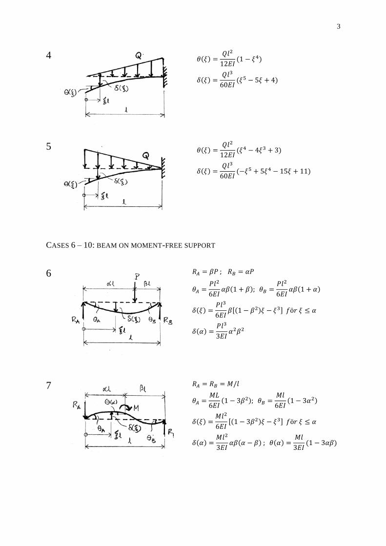
Bending of beams
In all cases shown,
E = elastic modulus
I = area moment of inertia
CASES 1 – 5: CANTILEVER BEAM
1
2
3
3
4
5
CASES 6 – 10: BEAM ON MOMENT-FREE SUPPORT
6
7

4
8
9
10
5
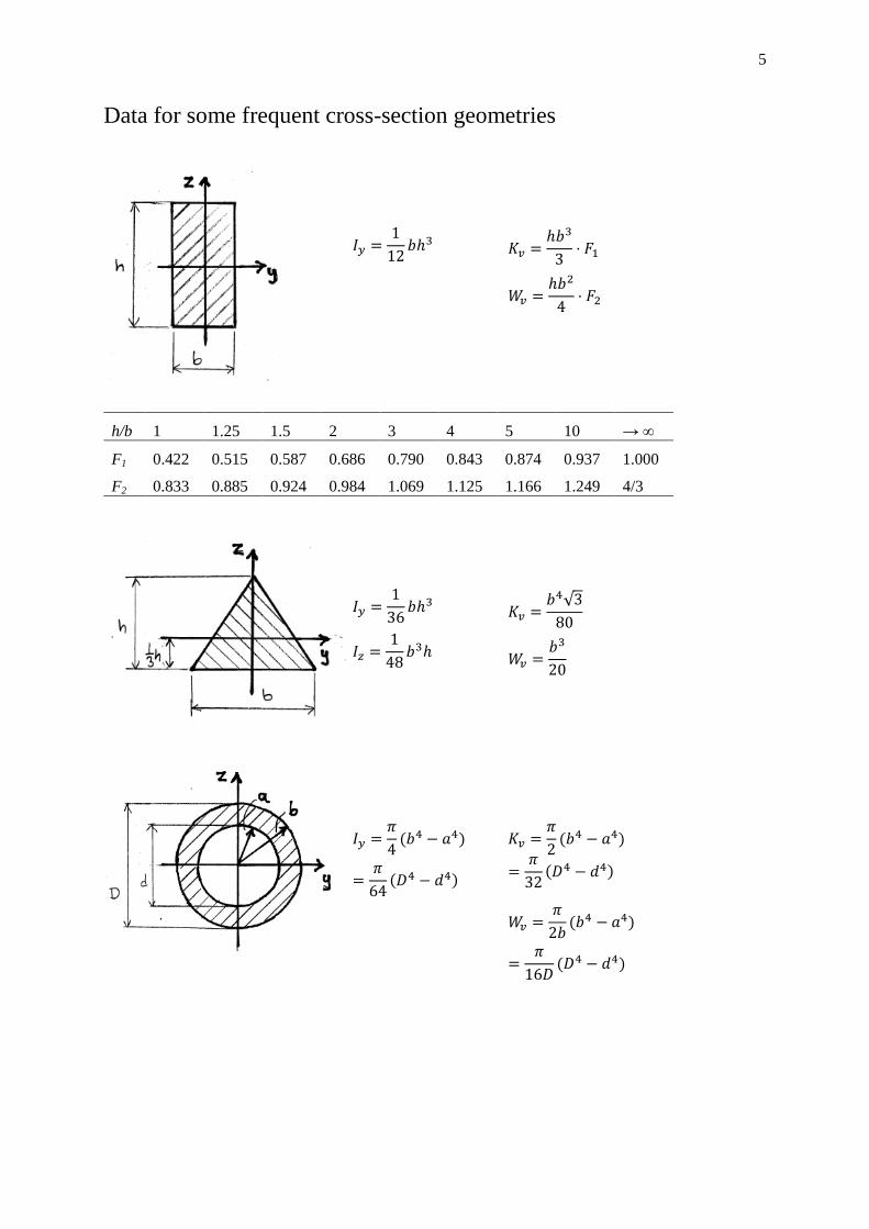
Data for some frequent cross-section geometries
h/b 1 1.25 1.5 2 3 4 5 10 → ∞
F1 0.422 0.515 0.587 0.686 0.790 0.843 0.874 0.937 1.000
F2 0.833 0.885 0.924 0.984 1.069 1.125 1.166 1.249 4/3
6
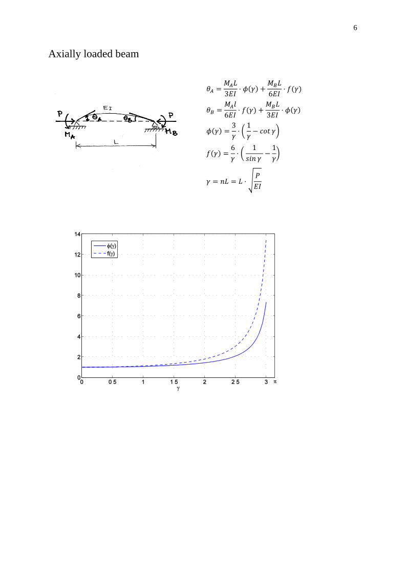
Axially loaded beam

7
Euler instability cases
In all 5 cases
E = elastic modulus
I = area moment of inertia
l = length
CASE 1 2 3 4 5
Bound-
ary
condi-
tion
A: free
B: clamped
A: pinned
B: pinned
A: pinned
B: clamped
A: clamped
B: clamped
A: clamped/
gliding
B: clamped

8
Westergaard solution for stress and displacement near a crack tip
MODE I
MODE II
MODE III
9
Note: In the displacement equations, the parameter depends on whether the situation is plane
deformation or plane stress:
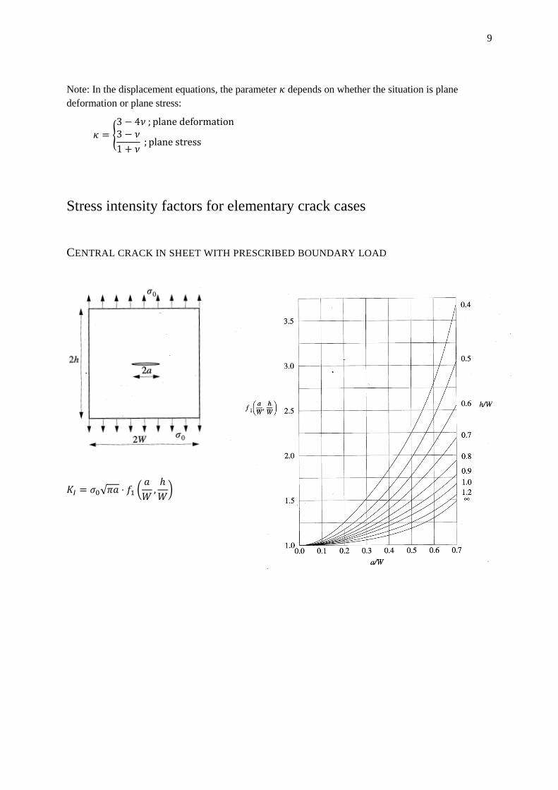
Stress intensity factors for elementary crack cases
CENTRAL CRACK IN SHEET WITH PRESCRIBED BOUNDARY LOAD

10
CRACKS STARTING AT CIRCULAR HOLE IN AN INFINITELY LARGE SHEET
DOUBLE EDGE CRACKS IN SHEET WITH PRESCRIBED BOUNDARY LOAD

11
SINGLE EDGE CRACK IN SHEET WITH PRESCRIBED BOUNDARY LOAD
EDGE CRACK IN STRIP WITH PRESCRIBED BENDING MOMENT LOAD

12
ELLIPTICAL SURFACE CRACK
ELLIPTICAL INTERNAL CRACK

13
Energy release rate
where
The following universal relations are valid between G and stress intensity factors:
Mixed-mode stress intensity factors
Criterion based on energy release rate:
Maximum tangential stress criterion:

14
Plastic zone near crack tip
The Dugdale model also gives expressions for the crack opening:
The J integral
The J integral is path-independent (provided that the strain energy function exists and has the prop-
erty everywhere in the region swept by when going from one path to another).
Further, if exists and has the above-mentioned property in the region enclosed by in the figure,

15
HCF: multiaxial stress states
Sines’ criterion:
1. In a case where , i.e., if all stress components vary in phase, the
following and can be used:
2. If we do not have , the above expression for is still valid,
whereas an improved expression must be used for :
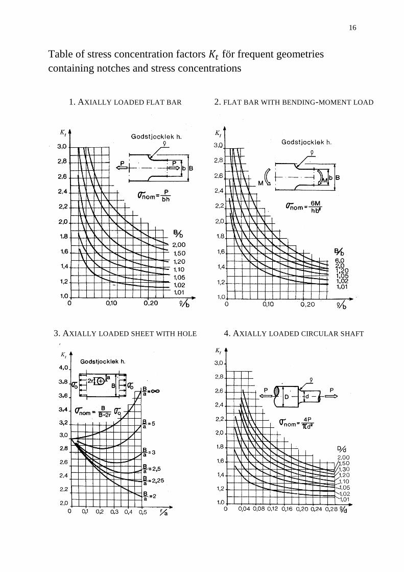
16
Table of stress concentration factors för frequent geometries
containing notches and stress concentrations
1. AXIALLY LOADED FLAT BAR 2. FLAT BAR WITH BENDING-MOMENT LOAD
3. AXIALLY LOADED SHEET WITH HOLE 4. AXIALLY LOADED CIRCULAR SHAFT

17
5. CIRCULAR SHAFT WITH BENDING-
MOMENT LOAD
6. CIRCULAR SHAFT WITH TORQUE LOAD
7. SHAFT WITH AXIAL GROOVE