formulation of detailed consumables … of detailed . consumables. management models ... for the...
TRANSCRIPT

26821 -H002-RO-00
FORMULATION OF DETAILED CONSUMABLES
MANAGEMENT MODELS FOR THE
DEVELOPMENT (PREOPERATIONAL) PERIOD OF
ADVANCED SPACE TRANSPORTATION SYSTEM
CONTRACT NO.NAS9-14264MBER 1976
VOLUME I
DETAILED REQUIREMENTS FOR
THE MISSION PLANNING PROCESSOR
14J7713119(N4AS-tR-15-1-i 6 ) FORMULATION or DETAILED -CA I CONSUNABLES MANAGEMENT MODfIS FOR THE YV Apot.PERIOD OFDEVELOPMENT (r-EOPERATIONA) Unclas ADVANCED SPACE TRAnSPORTATION SYSTEM. G3/16 -56923
DAILED (Tn1-Deense and spaceVOLUME 1:
DEC 1976'RECEIVED
Prepared by \ INPUT BRANCH
L.C. Connelly tL
Systems Analysis Section
TRW DEFEW AA C SPACE SYSTEMS G01
https://ntrs.nasa.gov/search.jsp?R=19770006176 2018-06-29T19:47:00+00:00Z

26821-HO02-RO-O0
Technical Report
for
Contract NAS 9-14264
Formulation of Detailed Consumables Management
Models for the Development (Preoperational)
Period of Advanced Space Transportation System
VOLUME I
DETAILED REQUIREMENTS FOR THE
MISSION PLANNING PROCESSOR
November 1976
Prepared by
L. C. Connelly
Systems Analysis Section TRW Defense and Space Systems Group
Houston, Texas

PREFACE
Future manned space programs that will have increased launch frequencies and reusable systems require an implementation of new consumables
and systems management techniques that will relieve both the operations support personnel and flight crew activities. These techniques must be
-developed for the optimum combination of an onboard and ground support
consumables management system consistent with the goals of the program.
Effective operational performance of the consumables management techniques
of a total system requires that a very explicit definition of the time,
place, and method of performance of each function be determined by trade
studies to ascertain that the operational methods do, indeed, meet these goals. This requires that the complete consumables management cycle be
considered by including the mission planning and scheduling functions,
prelaunch activities, onboard mission functions, ground mission support
functions, and postmission activities.
Formulation of models required for the mission planning and schedul
ing function and establishment of the relation of those models to prelaunch,
onboard, ground support, and postmission functions for the development phase of Space Transportation Systems (STS) was conducted under Contract NAS 9-14264
during the period 1 November 1975 to 31 October 1976. The preoperational Space Shuttle is used as the design baseline for the subject model formula
tions.
Analytical models were developed which consist of a Mission Planning Processor with appropriate consumables data base, a method of recognizing
potential constraint violations in both the planning and flight operations
functions, and a Flight Data File for storage/retrieval of information
over an extended period which interfaces with a Flight Operations Processor
for monitoring of the actual flights.
The Final Report for the Formulation of Detailed Consumables Management
Models for the Development Period of Advanced Space Transportation Systems consists of an Executive Summary and five Technical Volumes. The Technical
Volumes include information required for the implementation of a Consumables
Management System. The individual volumes consist of:
'AGE INTENTIONALI~TANM. iii

Volume I. Detailed Requirements for the Mission Planning Processor
Volume II. Consumables Data Base Workbook
Volume III. Study of Constraints/Limitations for STS Consumables Management
Volume IV. Flight Data File Contents
Volume V. Flight Operations Processor Requirements
Two additional documents were issued in the course of the contract
execution. These reports support the development of the Consumables
Management System. The reports are:
Study of Existing Analytical Models for STS Consumables Management, dated February 1976.
Documentation of Computer Routines Developed to Determine CyclicProbability (CYCPRO) Trends of Shuttle Heater Usage, dated September 1976.
This volume of the technical reports, Volume I, presents the detailed requirements for the Mission Planning Processor. The Mission Planning Processor is a user oriented tool for consumables management incorporating
the models developed under this contract.
iv
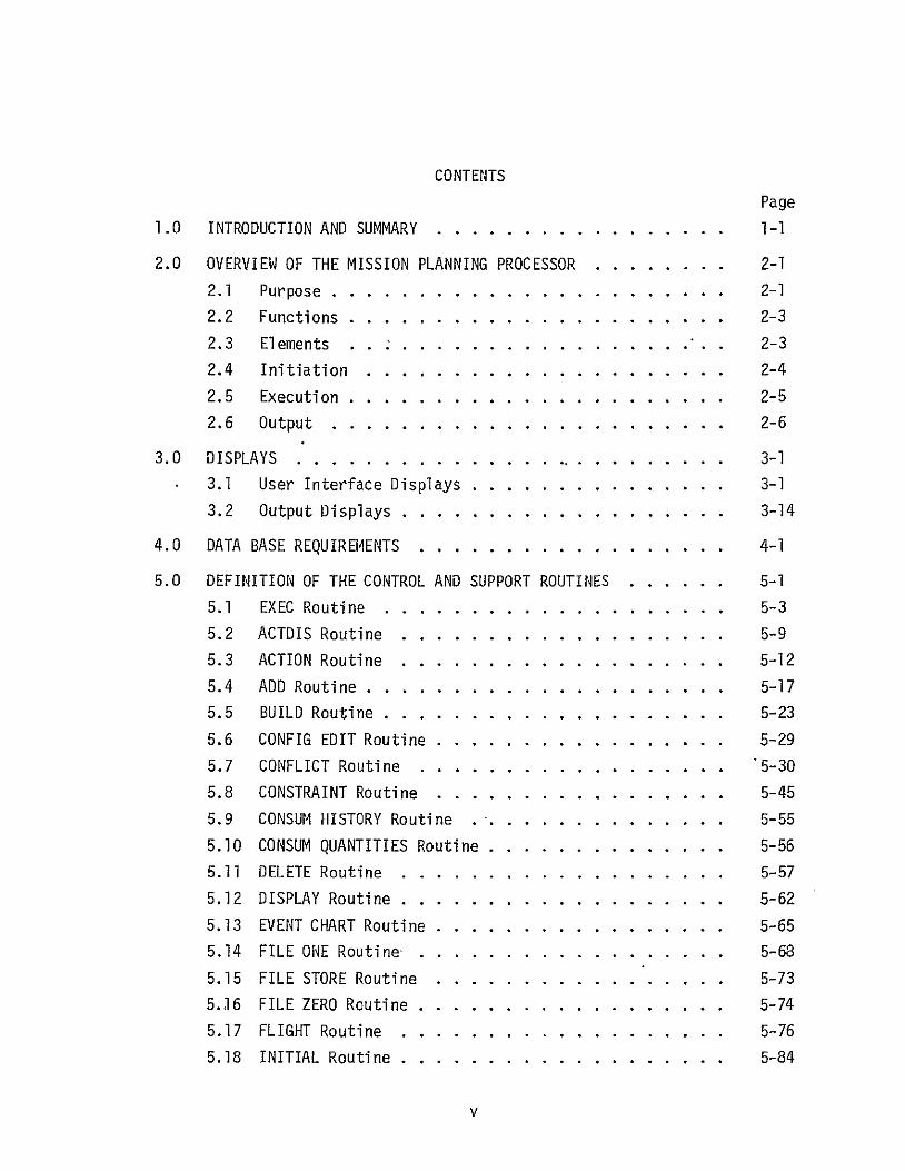
CONTENTS
Page
1.0 INTRODUCTION AND SUMMARY ........ ................. 1-1
2.0 OVERVIEW OF THE MISSION PLANNING PROCESSOR ........ 2-1
2.1 Purpose ................... ...... 2-1
2.2 Functions ........................ 2-3
2.3 Elements ... ............ .... . ..... 2-3
2.4 Initiation .. ....... .............. 2-4
2.5 Execution ................... ..... 2-5
2.6 Output ................... ..... 2-6
3.0 DISPLAYS ................... ................ 3-1 3.1 User Interface Displays ........ ........... 3-1
3.2 Output Displays ............ ............ 3-14
4.0 DATA BASE REQUIREMENTS ............ ......... ... 4-I
5.0 DEFINITION OF THE CONTROL AND SUPPORT ROUTINES.. . .. .5-1
5.1 EXEC Routine .............. ........ 5-3...
5.2 ACTDIS Routine ........... ...... .... 5-9 5.3 ACTION Routine ......... ............. 5-12
5.4 ADD Routine ..... ...... ........... 5-17
5.5 BUILD Routine ... .................... 5-23
5.6 CONFIG EDIT Routine.... . 5-29. ...........
5.7 CONFLICT Routine...... . ... .... 5-30. ....
5.8 CONSTRAINT Routine.... . 5-45. ...........
5.9 CONSUM HISTORY Routine .... ............ 5-55
5.10 CONSUM QUANTITIES Routine ............ .... 5-56
5.11 DELETE Routine ...... ...................... 5-57
5.12 DISPLAY Routine ...... ............. ..... 5-62
5.13 EVENT CHART Routine .... ................ 5-65 5.14 FILE ONE Routine..... .................. 5-68
5.15 FILE STORE Routine .... ........... .... 5-73 5.16 FILE ZERO Routine ... ............. ....... 5-74 5.17 FLIGHT Routine ............... ....... 5-76
5.18 INITIAL Routine ... ..................... 5-84
V

5
10
15
20
25
30
LIST OF FIGURES
Figure Page
1 Mission Planning Processbr Overview . ... .. .. 2-2
7 The Entry/Land Block Display Skeleton .... .. 3-8
2 The Configuration Block Display Skeleton . . ..... . 3-3 3 The Flight Block Display Skeleton.. . . .. .... 3-4
4 The Ascent Block Display Skeleton ... ...... .. 3-5 The On-Orbit Block Display Skeleton . ... .. .. 3-6
6 The Deorbit Block Display Skeleton ...... ...... 3-7
. .
8 The Orbital Phase Menu Display Skeleton . . ... .. 3-10 9 The OMS Maneuver Action Display 'Skeleton . . ..... 3-11
The Orbital Activity Menu Display Skeleton . ..... 3-12
11 The Payload Bay Doors Action Display Skeleton 3-13
12 Control and Support Routine Hierarchy. . 5-2. ... .. 13 Flow Diagram for the EXEC Routine ...... .. .... 5-5
14 Flow Diagram for the ACTDIS.Routine.. ... .. .. 5-10
Flow Diagram for the ACTION Routine ..... .. .. 5-14
16 Flow Diagram for the ADD Routine ...... ... .. 5-19 17 Flow Diagram for the BUILD Routine ...... .... 5-25
18 The Scheduling Conflict Table Skeleton ........ 5-33
19 The Master Compatibility Matrix... ...... .. 5-34
. . ... ....
21 Flow Diagram for the CONFLICT Routine ...... .. 5-36
The Compatibility Array . ... .. 5-35
22 The Rate Violation Table Skeleton ...... .... 5-47 23 Flow Diagram for the CONSTRAINT Routine ..... .. 5-48 24 Flow Diagram for the DELETE Routine ...... ..... 5-59
Flow Diagram for the DISPLAY Routine . . .... ... 5-63 26 Flow Diagram for the EVENT CHART Routine . ...... 5-65 27 Flow Diagram for the FILE ONE Routine . ..... .. 5-72 28 Flow Diagram for the FILE ZERO Routine . .. ..... 5-75 29 Flow Diagram for the FLIGHT Routine ..... .. .... 5-79
Flow Diagram for the INITIAL Routine ....... .... 5-85
QREOEDING PAGE BLANK NOT FILRM
vii

LIST OF FIGURES (Continued)
Figure Page
31 Flow Diagram for the IV INPUT Routine .......... ... 5-88
32 Flow Diagram for the LINECK Routine ..... .. .... 5-91
33 Flow Diagram for the OUTPUT Routine .. ........ ... 5-95
34 Flow Diagram for the PLAN Routine .... ..... .... 5-103
35 Flow Diagram for the POOL Routine ..... .......... 5-117
36 The ACTION-RATE Cross Reference Table Skeleton . . . 5-121
37 Flow Diagram for the RATE Routine ..... .......... 5-122
38 Flow Diagram for the SEQUENCE Routine ... ....... 5-130
39 Flow Diagram for the SPECIAL Routine ....... ... 5-137
40 Flow Diagram for the CFLT Routine ...... ....... 6-3
41 Flow Diagram for the COMS Routine ...... ....... 6-7
42 Flow Diagram for the CRCS Routine ....... ...... 6-10
43 Flow Diagram for the CATH Routine ..... ......... 6-13
44 Flow Diagram for the CREND Routine ... ....... ... 6-16
45 Flow Diagram for the CDOCK Routine ... ....... ... 6-19
46 Flow Diagram for the CUDOCK Routine .... ......... 6-22
47 Flow Diagram for the CEVA Routine ...... .. .... 6-26
48 Flow Diagram for the CIVA Routine ..... .......... 6-30
49 Flow Diagram for the CES Routine ..... ........... 6-33
LIST OF TABLES
Table Page
I Active Mode Display Cross Reference Table ... ..... 3-2
II Output Display Cross Reference Table ... ......... 3-14
III File 1 Data Set ...... .. .. ............. 5-69
IV Input Parameters Required to Schedule/ Unschedule an Activity ........... ........ 5-102
viii

1.0 INTRODUCTION AND SUMMARY
The purpose of this report is to document the detailed requirements for the Mission Planning Processor. The Mission Planning Processor is a user
oriented tool for consumables management and is part of the total consumables subsystem management concept presented in Reference 1.
A quasi top-down approach was applied to the design of the Mission Planning Processor. That is, interface requirements, input/output, and data base concepts were considered before computational processing. Existing
analytical models (Reference 2) were investigated for applicability before new models (References 3 and 4) were developed. An overview of the Mission
Planning Processor is presented in Section 2.0.
The Mission Planning Processor is being designed for an interactive
system using demand terminals for input/output/display and interfacing with an updateable mission data bank. The user interface concept is presented in Section 3.0 and the data base handling concept is presented in Section 4.0.
The control and support routines, presented in Section 5.0, provide the user interface, peripheral data handling, program control, and support functions required by the Mission Planning Processor for execution on an
interactive system. A description, interface requirements, definition of internal variables, listing of input data, processing flow diagram, and
listing of output data are presented for each routine.
The computational routines perform specific manipulations of consumables data base information. The computational routines are Space Shuttle
consumables subsystems oriented and are presented in Section 6.0.
The detailed requirements for the Mission Planning Processor presented in this report are independent of computer hardware and programming
language.
I-1

2.0 OVERVIEW OF THE MISSION PLANNING PROCESSOR
2.1 PURPOSE
Consumables management is a continuous process throughout the mission
planning cycle from long-range planning through post-flight analysis. The
Mission Planning Processor (Figure 1)'is a user oriented tool for consumables management. The user need not be a consumables analyst. The Mission Planning
Processor is being designed for an interactive system using demand mode
terminals for input/output/display and interfacing with the updateable Flight
Data Files. The files for each mission in the data bank are generated and
used by the Mission Planning Processor. The amount of detail in the mission
files is a function of where the mission lies in the planning cycle.
During long-range planning (Launch - 10 years) mission plans can be developed using discrete event data disassociated from the time of occurrence
of the event. The effects of these events on consumable usage can be tallied
by the Mission Planning Processor (RUN MODE = EVENT) to determine mission
feasibility and consumable subsystem requirements. The results can be stored
in the Flight Data Files (FILE 0) for recall.
During near-term planning (Launch - 6 years to Launch) the Mission
Planning Processor can be used iUN MODE = ACTIVE) to build and use mission
plans with increasing detail and fidelity to mission time of events. The
Mission Planning Processor will provide immediate feedback to the user con
cerning scheduling conflicts and consumable usage rate limit violations. The
user has the option to generate and display event timelines, consumable
usage versus mission time, and total consumables used and/or end of mission
reserves for each consumable subsystem. The results can be stored in the
Flight Data File (FILES I, 2, and 3) for recall.
2-1

CONSUMABLES MANAGEMENT SYSTEM: MISSION PLANNING PROCESSOR
CONTROL AND SUPPORT ROUTINES
TERMINAL UNIT
COMPUTATIONAL ROUTINES
FLIGHT DATA
I FILES
CONSUMABLES ANALYSIS DATA BASE
Figure 1. Mission Planning Processor Overview

2.2 FUNCTIONS
The Mission Planning Processor performs the following functions:
- a) Provides user interface through interactive CRT displays
b) Generates total mission consumable requirements
c) Acts as a scheduler for mission events that affect consumable usage
d) Provides immediate feedback of scheduling conflicts
e) Provides immediate feedback of consumable usage rate violations
f) Generates and displays detailed consumable analysis data on user request
g) Stores selected generated data in the Flight Data Files on user request.
2.3 ELEMENTS
The Mission Planning Processor consists of the following elements:
a) The displays/user interface
b) The Flight Data Files
c) The consumables analysis data base
d) The control and support routines
e) The computational routines.
The user of the Mission Planning Processor need not be a consumables analyst to perform consumable management functions. The user interface is
being designed to promote ease of input, immediate feedback of anomalies,
and active display of a minimum data set. The user can request the genera
tion and display of more detailed consumable analysis data if preferred, but the user need not understand the generation process. The user requests are
serviced through a series of interactive CRT displays. These displays are
discussed in detail in Section 3.0.
The Mission Planning Processor builds and uses the Flight Data Files
defined in Volume IV of this report. The amount of detail in the files is a function of where the mission lies in the planning cycle. Four files are
identified for each mission:
2-3

FILE 0 Contains data to reconstruct the event chart
FILE 1 Contains the minimum data set to operate the Mission Planning Processor-in the ACTIVE mode
FILE 2 Contains detailed consumables versus time data for each subsystem
FILE 3 Contains detailed consumables versus time data for individual elements and distribution networks for each subsystem.
The consumables analysis data base contains the characteristic activity and subsystem usage rate data required by the Mission Planning
Processor and is documented in Volume Ir of this report.
The control and support routines provide the user interface, peripheral data handling, program control, and support functions required by the Mission
Planning Processor. The control and support routines are presented in detail
in Section 5.0.
The computational routines calculate the specific consumables sub
system data required by the Mission Planning Processor. The computational
routines are presented in Section 6.0.
2.4 INITIATION
In the EVENT MODE, the Mission Planning Processor requires the consumables analysis influence variables as input. There are two methods to intro
duce the influence variables into the prograni:
a) The first time the mission-is executed; the influence variables are entered one at a time thrdugh the keyboard.
b) In subsequent executions the influence variables are entered from the FILE 0 data set stored in the Flight Data Files.
In the ACTIVE MODE, the Mission Planning Processor requires a mission timeline as input: There are two methods to introduce the mission timeline
into the program as a function of where the mission lies in the planning
cycle.
2-4

a) The first time the mission is executed, the timeline is entered event by event through keyboard entry. Even this mode is semiautomatic. Many standardized events (eat and sleep periods,etc.) are automatically scheduled as a function of the mission configuration.
b) Insubsequent executions the mission timeline is entered from the
FILE 1 data set stored in the Flight Data Files.
2.5 EXECUTION
In the EVENT MODE the influence variables, regardless of initiation
method, are used to calculate consumable usage and requirements. The results may be displayed and/or stored in the Flight Data Files.
Inthe ACTIVE MODE, the mission timeline, regardless of initiation
method, is used to create consumable usage rate blocks. Any scheduling
conflicts or rate violations will be fed back to the user and stored in conflict tables for later assessment. At this time in the execution, the user
may elect to generate and display detailed consumable analysis data or modify
the existing mission timeline.
Mission timeline modification is accomplished by user input through a
set of interactive displays. These displays are discussed in Section 3.1. The user may change the start and stop times of mission phases, schedule new events, modify existing events, or unschedule existing events. For
each change in the mission timeline, consumable usage rate blocks are
built for each consumable subsystem affected by the change. Any scheduling
conflicts or rate violations will befedback to the user and stored in
conflict tables for later assessment. At this time in the execution, the
user may elect to generate and display detailed consumable analysis data
and/or store selected data in the Flight Data Files.
The following detailed consumable analysis data can be generated and
displayed at user option:
a) An event chart that lists the number and types of events scheduled without reference to mission time.
b) A timeline listing scheduled events versus mission time without reference to consumables usage.
2-5

c) The consumables usage versus time for each consumables subsystem.
d) The total consumables used and end-of-mission quantities for each -consumables subsystem.
2.6 OUTPUT
The results of the Mission Planning Processor execution can be output
via CRT displays at the user terminal and/or stored in the Flight Data Files. The outputdisplays are discussed in Section 3.2. The Flight Data Files
have been addressed previously in this section.
2-6

3.0 DISPLAYS
The Mission Planning Processor is being designed for an interactive
system and uses the CRT display unit at the user terminal as an integral
part of the program. There are two types of Mission Planning Processor
displays:
a) The interactive USER INTERFACE displays
b) The read only OUTPUT displays.
The use of these displays in the ACTIVE MODE is discussed in the following
subsections.
3.1 USER INTERFACE DISPLAYS
The user interface with the Mission Planning Processor is through a
set of interactive displays. Table I lists the user interface displays for
the ACTIVE MODE. Except for the first display executed, the progression
through the displays in the ACTIVE MODE is controlled by user input.,
The first display executed is a function of the data option selected
for the ACTIVE MODE. If the INITIAL data option is selected, the CONFIGURATION
BLOCK display illustrated in Figure 2 is automatically executed. The user may
enter the mission-dependent parameters identified on the display'to create a
mission configuration. On completion, the user enters the PROCEED instruc
tion to continue the mission planning task. The remaining user interface
displays are executed as discussed below for the RESTART data option.
If the RESTART data option is selected, the FLIGHT BLOCK display
illustrated in Figure 3 is automatically executed. Entry of the line number
corresponding to the requested mission phase will execute the PHASE BLOCK
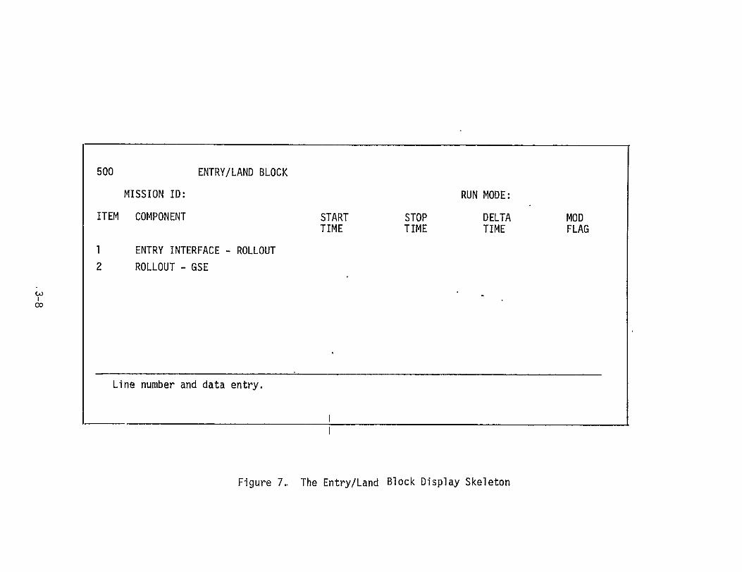
displays. The Ascent, On-Orbit, Deorbit, and Entry/Land phase block dis
plays are illustrated in Figures 4 through 7, respectively. The FLIGHT BLOCK
display is used for Prelaunch requests.
On the Prelaunch, Ascent, Deorbit, and Entry/Land displays the user
can modify mission times. Any modifications will be noted on the display
by the MOD flag. The modification is accomplished by entering the line
number corresponding to the phase component to be modified and the time
parameter value to be changed.
3-1

Table I. Active Mode Display Cross Reference Table
DISPLAY TYPE DISPLAY NAME
CONFIG CONFIGURATION
FLIGHT FLIGHT BLOCK
PHASE BLOCK ASCENT
PHASE BLOCK ON-ORBIT
PHASE BLOCK DEORBIT
PHASE BLOCK ENTRY/LAND
MENU ORBITAL PHASE MENU
MENU ORBITAL ACTIVITY MENU
ACTION OMS MANEUVER
ACTION RCS TRANSLATION
ACTION ATTITUDE HOLD
ACTION RENDEZVOUS
ACTION STATION KEEPING
ACTION DOCK
ACTION UNDOCK
ACTION PTC
ACTION EVA
ACTION IVA
ACTION MANIPULATOR OPS
ACTION IMU ALIGNMENT
ACTION PAYLOAD BAY DOORS
ACTION PAYLOAD CONSUMABLES
ACTION COMPUTER
ACTION TV
ACTION DOWNLINK
ACTION UPLINK
ACTION FUEL CELL PURGE
ACTION EAT
ACTION SLEEP
ACTION WASTE MANAGEMENT
ACTION APU CHECKOUT
3-2
LINE #
1
2
3
4
5
2
4
1
2
3
4
5
6
7
8
9
10
11
12
1
2
3
4
5
6
7
8
9
10
11
DISPLAY ID ACTION ID
90
100 -1
200 -2, -5
300 -6
400 -7, -8
500 -9, -10
320
340
321 1
322 2
323 3
324 4
325 5
326 6
327 7
328 8
329 9
330 10
331 11
332 12
341 13
342 14
343 15
344 16
345 17
346 18
347 19
348 20
349 21
350 22
351 23
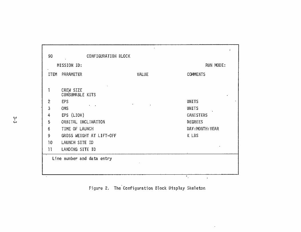
90 CONFIGURATION BLOCK
MISSION ID: RUN MODE:
ITEM PARAMETER VALUE COMMENTS
1 CREW SIZE
CONSUMABLE KITS
EPS UNITS
3 OMS UNITS
4 EPS (LIOH) CANISTERS
5 ORBITAL INCLINATION DEGREES
6 TIME OF LAUNCH DAY:MONTH:YEAR
9 GROSS WEIGHT AT LIFT-OFF K LBS
10 LAUNCH SITE ID
11 LANDING SITE ID
Line number and data entry
Figure 2. The Configuration Block Display Skeleton

100 FLIGHT BLOCK
MISSION ID: RUN MODE:
ITEM PHASE START STOP DELTA MOD TIME TIME TIME FLAG
1 PRELAUNCH
2 ASCENT
3 ON ORBIT
4 DEORBIT
5 ENTRY/LAND
Line number entry or line number and data entry.
Figure 3. The Flight Block Display Skeleton

200 ASCENT BLOCK
MISSION ID: RUN MODE:
ITEM COMPONENT START TIME
STOP TIME
DELTA TIME
MOD FLAG
1
2
3
4
GSE-LIFT OFF
LIFT OFF - MECO
MECO - ETS
ETS - OMS IGNITION
Line number and data entry.
Figure 4. The Ascent Block Display Skeleton

300 ON ORBIT BLOCK
MISSION ID: RUN MODE:
ITEM REQUEST START TIME
STOP TIME
DELTA TIME
MOD FLAG
1
2
3
OMS IGNITION - DEORBIT
ORBITAL PHASE MENU
ORBITAL PHASE SUMMARY
4
5
ORBITAL ACTIVITY MENU
ORBITAL ACTIVITY SUMMARY
Line number entry or line number and data entry.
Figure 5. The On-Orbit Block Display Skeleton

400
ITEM
I
2
DEORBIT BLOCK
MISSION ID:
COMPONENT
PREP - BURN
BURN - ENTRY INTERFACE
START TIME
STOP TIME
RUN MODE:
DELTA TIME
MOD FLAG
Line number and data entry
Figure 6. The Deorbit Block Display Skeleton
cI
500
ITEM
1
2
ENTRY/LAND BLOCK
MISSION ID:
COMPONENT
ENTRY INTERFACE - ROLLOUT
ROLLOUT - GSE
START TIME
STOP TIME
RUN MODE:
DELTA TIME
MOD FLAG
Line number and data entry.
Figure 7.. The Entry/Land Block Display Skeleton

The On-Orbit display allows the user more latitude in modifying the
mission. The phase time can be changed on line number 1 in the same manner
as the Prelaunch, Ascent, Deorbit, and Entry/Land displays. Entering line
numbers 2 or 4 will cause the MENU displays to be executed. The MENU dis
plays allow specific mission events to be selected for modification. The
Orbital Phase Menu display is illustrated in Figure 8 and the Orbital
Activity Menu display is illustrated in Figure 10. Entering line numbers
3 or 5 on the On-Orbit display will allow all the ACTION displays associated
with the events listed on a MENU display to be executed in a read only
sequence.
On the MENU displays, entering the line corresponding to the selected
mission event will cause the ACTION display for the event to be executed.
Figure 9 illustrates the ACTION display for the OMS Maneuver selected by
entering line number 1 on the Orbital Phase Menu. Figure 11 illustrates
the ACTION display for the Payload Door activities selected by entering line
number 1 on the Orbital Activity Menu.
Each scheduled occurrence of an event is itemized on the ACTION dis
play corresponding to the event. The user may modify the mission plan by
entering the line number (n)of the itemized event occurrence to be modified
as follows:
n Modify occurrence n. The parameters to be changed are also entered.
-n Unschedule occurrence n.
n+l Schedule another occurrence of the event. The event data required are also entered.
The results of modifications entered through any display will be fed
back to the user on that display. Modifications entered on any display that
affect other displays will automatically update the other displays.
3-9

320 ORBITAL PHASE MENU
MISSION ID: RUN MODE:
ITEM ACTION NUMBER SCHEDULED MOD FLAG
1 OMS MANEUVER 2 RCS TRANSLATION 3 ATTITUDE HOLD 4 RENDEZVOUS 5 STATION KEEPING 6 DOCK 7 UNDOCK 8 PTC 9 EVA 10 IVA 11 MANIPULATOR OPS 12 IMU ALIGNMENT
Line number entry.
Figure 8- The Orbital Phase Menu Display Skeleton

321 OMS MANEUVER
MISSION ID: RUN MODE:
ITEM START STOP DELTA TIME TIME VELOCITY
1
2
3
n
Line number and data entry or negative line number entry.
Figure 9. The OMS Maneuver Action Display Skeleton

340 ORBITAL ACTIVITY MENU
MISSION ID: RUN MODE:
ITEM ACTION NUMBER SCHEDULED MOD FLAG
1 2 3 4 5 6 7 8 9 10 11 12
PAYLOAD DOORS PAYLOAD CONSUMABLES COMPUTER TV DOWNLINK UPLINK FUEL CELL PURGE EAT PERIOD SLEEP PERIOD WASTE MANAGEMENT APU CHECKOUT CO2 REMOVAL
Line number entry.
Figure 10. The Orbital Activity Menu Display Skeleton

341 PAYLOAD BAY DOORS
MISSION ID: RUN MODE:
ITEM TIME TIME MOD OPEN CLOSE FLAG
1
2
3
n
Line number and data entry or negative line number entry.
Figure 11. The Payload Bay Doors Action Display Skdleton

3.2 OUTPUT DISPLAYS
The user may request generation and display of more detailed consumable
analysis data. Table II lists the Output display options. These displays
are executed in a read only mode. The formats for these displays will be
defined during program implementation.
Table II. Output Display Cross Reference Table
DISPLAY TYPE DISPLAY NAME LINE # DISPLAY ID ACTION ID
OUTPUT CONFLICT TABLE 2 2000
OUTPUT EVENT CHART 3 3000
EVENT SUMMARY 1 3100
EVENT INFLUENCE VARIABLE 2 3200
EVENT OMS CONSUMABLES 3 3300
EVENT .RCS CONSUMABLES' 4 3400
EVENT EPS CONSUMABLES 5 3500
EVENT ECLSS CONSUMABLES 6 3600
OUTPUT TIMELINE 4 4000
OUTPUT CONSUMABLE HISTORY 5 5000
HISTORY OMS HISTORY 1 5100
HISTORY RCS HISTORY 2 5200
HISTORY EPS HISTORY 3 5300
HISTORY ECLSS HISTORY 4 5400
OUTPUT CONSUMABLE QUANTITIES 6 6000
3-14

4.0 DATA BASE REQUIREMENTS
The Mission Planning Processor interfaces with three distinct data
base areas:
a) The Flight'Data Files
b) The consumables analysis data base
c) The COMPOOL.
The Flight Data Files contain the data generated and subsequently
used by the Mission Planning Processor. The data files have been discussed inSection 2.3 and are defined in detail inVolume IVof this report.
The consumables analysis data base contains the characteristic event data (i.e., prep time, post time, consumables usage rates, etc.) and
subsystem data required by the Mission Planning Processor. The data are
defined in detail inVolume II of this report.
The COMPOOL isan active area of the data base. That is,the data
required by the Mission Planning Processor during execution istemporarily
stored inand passed through the COMPOOL.
4-1

5.0 DEFINITION OF THE CONTROL AND"SUPPORT ROUTINES
The control and support routines for the Mission Planning Processor
are defined in the following subsections. A description, interface require
ments, definition of internal variables, listing of input data, processing
flow diagram (ifrequired), and listing of output data are presented for
each routine.
The EXECUTIVE routine is presented first, followed by the remaining
routines in alphabetical order. Figure 12 illustrates the control and sup
port routine hierarchy illustrating the relationship between the individual
routines.
5-1

oI IV INPUT
INITIAL
EXEC
FILE ONE
CONPIG EDIT
FILE STORE
OUTPUT
iII EVENT CHART
FILE
ZERO
TIME LINE
I DISPLAY
DISPLAY
I CONA4 CONSUM HISTORY QUANTITIES
4 ----4 ...1 COMPUTATIONALROUTINES
L -- - ---------------
SPECIAL
.
BUILD
II
RATE CONFLICT
C--OS--TI CONSTRAINT
PLAN
01 0
ADD FLIGHT
1 1
LINECK DISPLAY
POOL DELETE RATE
SEQUENCE ACTDIS ACTION CONSTRAINT
RATE CONFLICT SPECIAL
CONSTRAINT COMPUTATIONAII IFuOUTiNES
Figure 12. Control and Support Routine Hierarchy

5.1 EXEC ROUTINE
. Description - The EXEC routine manages the Mission Planning Processor; calls the other control and support routines as directed by user instructions input through the keyboard unit; and provides tutorial/warning displays to
the user through the CRT display unit.
Interface
I/0 DEVICES - Terminal KEYBOARD and CRT units. DATA BASE - COMPOOL for output only. ROUTINES CALLING EXEC - None. ROUTINES CALLED BY EXEC - IV INPUT, OUTPUT, FILE ONE, INITIAL,
BUILD, CONFIG EDIT, and PLAN routines.
Internal Variables - None
Input - The EXEC routine requires the following instructions and data input through the KEYBOARD unit:
RUN MODE Mission Planning Processor operation mode; EVENT - Computer aided event chart
generation only. ACTIVE - Interactive mission planning.
DATA OPTION Required in ACTIVE mode to determine source of initiil mission planning data;
INITIAL - Data input through terminal. RESTART - Data initialized through Mission Data
File.
INSTRUCTIONS Entered through KEYBOARD unit; PROCEED - Continue processing. DISPLAY - Initiate output options.EXIT - Terminate processing.
Processing - The flow diagram of the EXEC routine is presented in
Figure 13.
5-3

Output- The EXEC routine transmits the following data through the
COMPOOL:
RUN MODE Mission PlaEVENT
ACTIVE
nning Processor operation mode; - Computer aided event chart generation only.
- Interactive mission planning.
The EXEC routine also provides the following warning displays to the user through the CRT display unit:
INCORRECT RUN MODE. INCORRECT DATA OPTION. INCORRECT INSTRUCTION.
5-4

ROUTINE START EXEC
PAGE 1 OF 4
ENTER JKY-RUN
RMODEEVENT
PASS RUN I
MODE FOR USE BY COMPOOL ROUTINE OUTPUT
MOE.YES
NO NO
MOD N WRNNGCR EQALUNCRREC
YAIBESFigure 13.Fo1Darmfo/h3XE otn
2/1e1. lw iga o heEE otn
CALL5

/ROUTINE EXEC PAGE 2 OF 4
CALL OUTPUT TO DISPLAY EVENT CHART
2/
Figure 13. Continued
5-6

ROUTINE
1/3 EX EC PAGE 3 OF 4
KEY-DATA
BOARDI OPTION
CALL FILE ONE YES OPTIO TO LOADT FILE I DATA
EQUAL RESTART
CALLOPTIONC BU CONFIG EDITTO EDIT EQUALCINITIAL WARNINGiINCORRECT
CONFIGURATION DATA OPTION
CALL INITIAL TO -BUILD
FILE 1DATA TABES
CALL BUILD TO RECREATE CONFLICT, RATE, AND VIOLATION TABLES
2/37
Figure 13. Continued
5-7

ROUTINE PAGE 4 OF 4
KEY- ENTER BOARD NEXT
INSTRUCTION
LCALLTPLTOUTPUT
"LI PROCEED NOWARNINGCR
J i NSTR°CTI°Oi
CALL
PLAN1/ TO ODIFY MISSION PLAN
NO5-8
CALL OUTPUT'
Figure 13. Concluded
5-8

5.2 ACTDIS ROUTINE
Description - The ACTDIS routine determines which action identifier
is required to schedule or unschedule an event and ifthe event to be
scheduled is cyclic.
Interface
I/0 DEVICES - None. DATA BASE - COMPOOL for both input and output; and Consumables
Analysis Data Base for input. ROUTINES CALLING ACTDIS - ADD ahd DELETE routines. ROUTINES CALLED BY ACTDIS - None.
Internal Variables - None.
Input - The ACTDIS routine requires the following input data accessed
through the COMPOOL:
Z The display variable Z = to the identifier of the MENU display being processed (see Table I for ID values).
X The display variable X = to the identifier of the ACTION display being processed (see Table I for ID values).
The ACTDIS routine requires the following input data from the
Consumables Analysis Data Base:
TABLE The Active Mode Display Cross Reference Table (as defined in Table I).
Processing - The flow diagram of the ACTDIS routine is presented in
Figure 14.
Output - The ACTDIS routine transmits the following data through
the COMPOOL:
J The ACTION identifier required by the event to be scheduled or unscheduled (see Table I for the values of J).
CYCLIC The CYCLIC flag is set if the event to be scheduled is a cyclic event: 0 = NON CYCLIC event 1 = CYCLIC event
5-9

ROUTINE
ACTDIS PAGE I OF 2
ENTER
COMPOOL VARIABLESZ AND X
CONSUM-ABLES READ ACTIVE ANALYSIS MODE DISPLAY DATA CROSS REFERENCE BASE TABLE
EXTRACT ACTION IDENTIFIER J AS A FUNCTION OF DISPLAY VARIABLES Z, X
PASS ACTION 1 IDENTIFIER J COMPOOL
Figure 14. Flow Diagram for the ACTDIS Routine
5-10

ROUTINE
ACTDIS PAGE 2 OF 2
1/2
IF J:TO SET8,12,14,15 YES CYCLIC FLAG
16,19,20,21 , =1
SETCYCLIC FLAG
=0
PASS
CYCLIC FLAG COMPOOL
Figure 14. Concluded
5-11
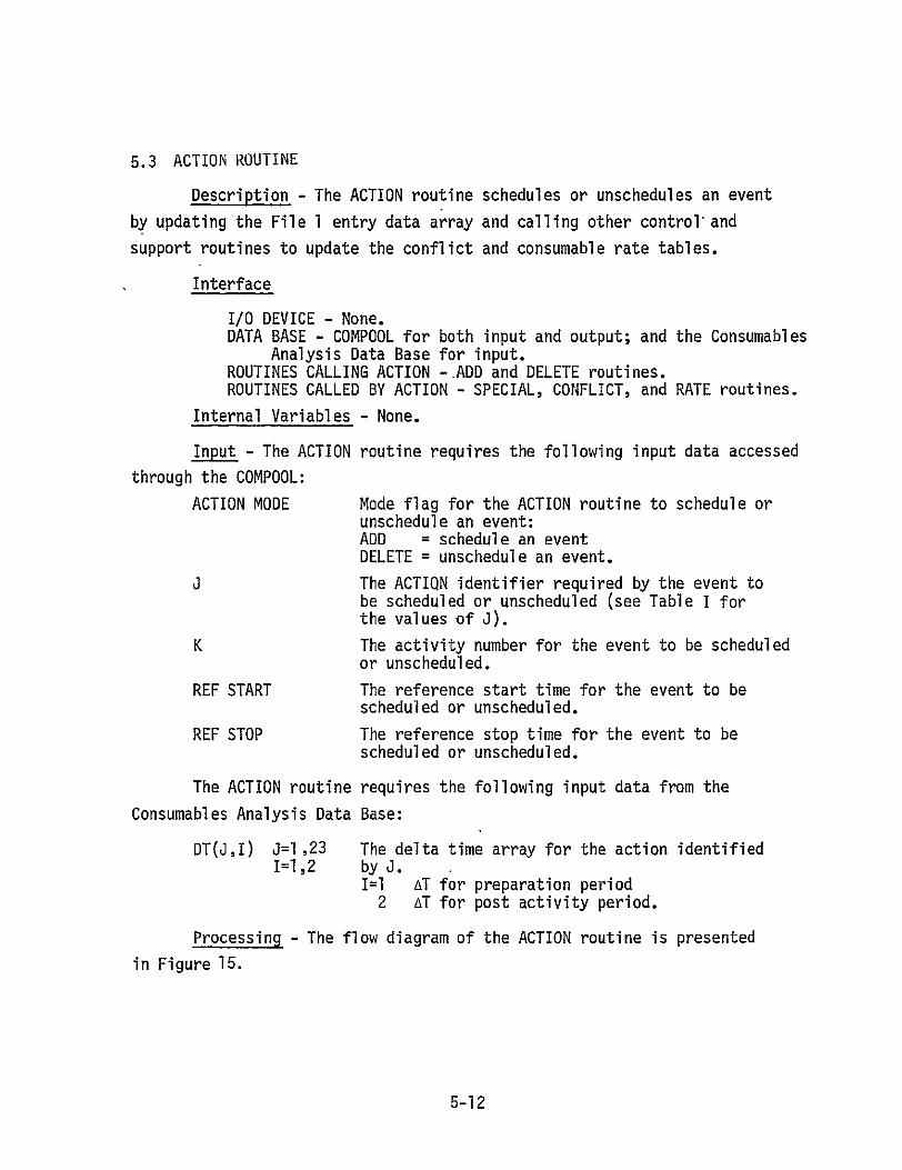
5.3 ACTION ROUTINE
Description - The ACTION routine schedules or unschedules an event
by updating the File 1 entry data array and calling other control and
support routines to update the conflict and consumable rate tables.
Interface
I/0 DEVICE - None. DATA BASE - COMPOOL for both input and output; and the Consumables
Analysis Data Base for input. ROUTINES CALLING ACTION --ADD and DELETE routines. ROUTINES CALLED BY ACTION - SPECIAL, CONFLICT, and RATE routines.
Internal Variables - None.
Input - The ACTION routine requires the following input data accessed
through the COMPOOL:
ACTION MODE Mode flag for the ACTION routine to schedule or unschedule an event: ADD = schedule an event DELETE = unschedule an event.
The ACTION identifier required by the event to be scheduled or unscheduled (see Table I for the values of J).
K The activity number for the event to be scheduled or unscheduled.
REF START The reference start time for the event to be scheduled or unscheduled.
REF STOP The reference stop time for the event to be scheduled or unscheduled.
The ACTION routine requires the following input data from the
Consumables Analysis Data Base:
DT(J,I) J=1 ,23 The delta time array for the action identified I=1,2 by J.
I=1 AT for preparation period 2 AT for post activity period.
Processing - The flow diagram of the ACTION routine is presented
in Figure 15.
5-12

Output - The ACTION routine transmits the following data through the COMPOOL;
AT(K,I) I=1,5 Entry data array for activity K
I=l prep start time 2 reference start time 3 reference stop time 4 post end time 5 special parameter, a function of ACTION
Identifier J: J=1,2,4,6, or 7; AT(K,5) = AV J=9,10,20,21, or 22; AT(K,5) = Number of crew.
5-13

ROUTINE ACTION PAGE I OF 3
ENTER
EXTRACT ACTION
COMPOOL MODE, ACTION IDENTIFIER J, AND ACTIVITY#K
~SET AT(K,I)
MODE 1=1,5 = =ADDJ BLANK
YES
SET AT(K,5) PASS AT(K,I)
=0 I=1,5I COMPOOL
COMPOOL PASS AT(K,5)
41/2
Figure 15. Flow Diagram for the ACTION Routine
5-14

ROUTINE ACTIONPAGE 2 OF 3
CALL SPECIAL FOR COMPUTATIONAL DATA F(J)
EXTRACT
AT(K,2) REF START AND REF STOP
CNUABLE
DAT BASE
READ DELTA TIME ARRAY DT(J,I) 1=1,2 FOR ACTION'J
AT(K,1 ) AT(K,2) AT(K,3)
AT(K,4)
= REF START-DT(J,I ) = REF START = REF STOP
= REF STOP+DT(J,2)
PASS AT(K,I)
I=1,4 COMPOOL
1/3
Figure 15. Continued
5-15
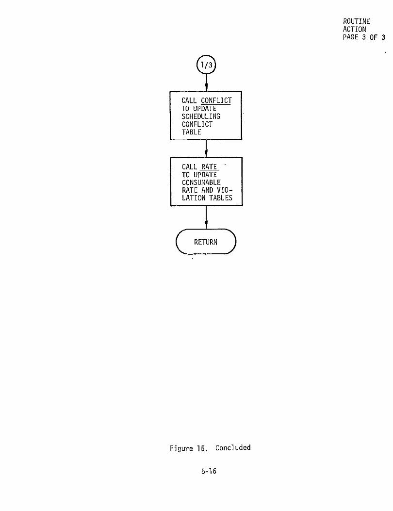
ROUTINE ACTION PAGE 3 OF 3
CALL CONFLICT TO UPDATE SCHEDULING CONFLICT TABLE
CALL RATE TO UPDATE CONSUMABLE RATE AND VIO-LATION TABLES
cRETURND
Figure 15. Concluded
5-16

5.4 ADD ROUTINE
Description - The ADD routine schedules an event by directly and
indirectly updating the File 1 data set and-indrectly-updatig the subsystem
rate and conflict tables affected by the new event.
Interface
I/0 DEVICES - None. DATA BASE - COMPOOL for both input and output. ROUTINES CALLING ADD - PLAN routine. ROUTINES CALLED BY ADD - POOL, ACTDIS, ACTION, and SEQUENCE
routines.
Internal Variables
CYCLIC STOP If the event to be scheduled is a cyclic event, the CYCLIC STOP time is set.
Input - The ADD routine requires the following input data accessed
through the COMPOOL:
K Activity number for event to be scheduled0
3 Action identifier for the event to be scheduled.
CYCLIC The CYCLIC flag is set ifthe event to be scheduled is a cyclic event: 0 = NON CYCLIC event 1 = CYCLIC event.
If CYCLIC = I, the following additional input data accessed through
the COMPOOL is required by the ADD routine:
REF START The reference start time for the event cycle.
REF STOP The reference-stop time for the event cycle.
Duty The duration of each event in the cycle.
Period The duration of each period in the cycle.
Processing - The flow diagram of the ADD routine is presented in
Figure 16.
5-17

Output - The ADD routine transmits the following data through the
COMPOOL:
NN(K)=J K=I,N Activity number K is an ACTION J.
IN(J) J=1,23 Number of ACTION J items scheduled.
NNN(I,J)=K I=IN(J) Activity number K is the Ith item of ACTION J=1,23 J scheduled.
ACTION MODE=ADD Mode flag for the ACTION routine to schedule an event.
If CYCLIC=l, the following additional data is transmitted through
the COMPOOL:
REF START The reference start time for each event in the cycle.
REF STOP The reference stop time for each event in the cycle.
5-18
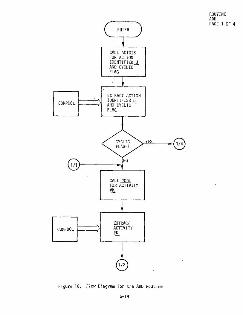
ROUTINE
ADD PAGE 1 OF 4
ENTER
CALL ACTDIS FOR ACTION IDENTIFIER J AND CYCLIC
FLAG
EXRACT ACTIONSIDENTIFIER J COMPOOL AND CYCLIC
FLAG
CALL POOL FOR ACTIVITY #K
1/2I YS /
EXTRACT COMPOOL ACTIVITY
-19&K
Figure 16. Flow Diagram for the ADD Routine
5-19

ROUTINE ADD
/PAGE 2 OF 4
SET CROSS REF-ERENCE PARAM-ETERS IN FILE 1 DATA
NN(K)=JIN(a)=IN(J)+l NNN(IN(J),J)=K
SET ACTION
MODE = TO ADD
PASS ACTION MODE AND CROSS REF COMPOOLPARAMETERS
CALL ACTION TO BUILD ENTRY DATA ARRAY, AT(K,I) I=I, 5, FOR ACTIVITY K IN FILE 1 DATA; TO UPDATERATE AND CONFLICT TABLES FOR SUBSYSTEMS AFFECTED BY ACTIVITY K
CALL-SEQUENCE TO BUILD SCHEDULING PARAMETERS FOR
ACTIVITY K IN FILE I DATA
Figure 16. Continued
5-20

ROUTINE ADD PAGE 3 OF 4
+1/3
REF START REF START + PERIOD
PASS
REF STARTCOPL
Figure 16. Continued
5-21

ROUTINEADD
PAGE 4 OF 4
EXTRACT REF START, DUTY,
COMPOOL PERIOD, AND REF STOP
CYCLIC STOP = REF STOP
REF STOP = REF'START + DUTY
PASS REF STOP COMPOOL
Figure 16. Concluded
5-22
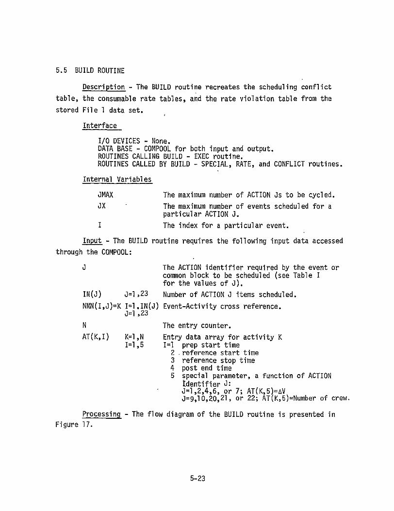
5.5 BUILD ROUTINE
Description - The BUILD routine recreates the scheduling conflict
table, the consumable rate tables, and the rate violation table from the
stored File 1 data set.
Interface
I/0 DEVICES - None. DATA BASE - COMPOOL for both input and output. ROUTINES CALLING BUILD - EXEC routine. ROUTINES CALLED BY BUILD - SPECIAL, RATE, and CONFLICT routines.
Internal Variables
JMAX The maximum number of ACTION Js to be cycled.
JX The maximum number of events scheduled for a particular ACTION J.
I The index for a particular event.
Input - The BUILD routine requires the following input data accessed
through the COMPOOL:
The ACTION identifier required by the event or common block to be scheduled (see Table I for the values of J).
IN(J) j=1,23 Number of ACTION J items scheduled.
NNN(I,J)=K I=l.IN(J) Event-Activity cross reference. 0=1 ,23
N The entry counter.
AT(K,I) K=I,N Entry data array for activity K 1=1,5 1=1 prep start time
2 reference start time 3 reference stop time 4 post end time 5 special parameter, a function of ACTION
identifier J: J=1,2,4,6, or 7; AT(K,5)=AVJ=9,10,20,21, or 22; AT(K,5)=Number of crew.
Processing - The flow diagram of the BUILD routine is presented in
Figure 17.
5-23

Output - The BUILD routine transmits the following data through
the COMPOOL:
ACTION MODE=ADD Mode flag for the ACTION routine to schedule an event,
J The ACTION identifier required by the event to be scheduled (see Table I for the values of J).
K Activity number for the event to be scheduled. REF START The reference start time for the event to be
scheduled. REF STOP The reference stop time for the event to be
scheduled.
5-24

ROUTINE BUILD PAGE 1 OF 4
tENTER
SET ACTION MODE=ADD
SET ACTION IDENTIFIER J=O
PASS ACTION MODE AND ACTION COMPOOL IDENTIFIER J
CALL SPECIAL FOR ACTION IDENTIFIER J
EXTRACT COPOOL ACTION
IDENTIFIER J
Figure 17. Flow Diagram for the BUILD Routine
5-25

ROUTINE BUILD PAGE 2 OF 4
1/2
d~l 'SET"YES J JMAX=24
-EXTRACT CROSS [
REFERENCE CALL RATE PARAMETERS COMPOOL TO RECEATE FROM FILL I RATE AND DATA SET VIOLATION TABLES
d~X=IN(j)I
K=NNN(I,J)
Figure 17. Continued
5-26

ROUTINE BUILD PAGE 3 OF 4
1/3
EXTRACT ENTRY DATA-ARRAY
COMPOOL AT(K,I) 1=1,5 FOR ACTIVITY #K FROMFILE I DATA
REF START = AT(K,2)-
REF STOP = AT(K,3)
PASS ACTION 1
IDENTIFIER J, ACTIVITY #K, COMPL REF START, AND REF STOP
CALL CONFLICT
TO RECREATE CONFLICT
TABLE
Figure 17. Continued
5-27

ROUTINE
BUILD PAGE 4 OF 4
CALL SPECIAL FOR COMPUTATIONAL DATA F(J)
CALL RATE TO RECREATE RATE AND VIOLATION
TABLES
I=JX sO. I=I+I
J=~lNOJ=JMAX
Figure 17. Concluded
5-28

5.6 CONFIG EDIT ROUTINE
Description - The CONFIG EDIT routine allows the user to modify the mission configuration data stored in File I of the Flight Data Files.
Interface
I/0 DEVICES - Terminal KEYBOARD and CRT units. DATA BASE - COMPOOL for both input and output. ROUTINES CALLING CONFIG EDIT - EXEC routine. ROUTINES CALLED BY CONFIG EDIT - None.
Internal Variables - None.
Input - The CONFIG EDIT routine can accept the following input data
entered through the terminal KEYBOARD unit or through COMPOOL:
CONFG(I) I=1,11 Mission configuration data (see Table III for parameter definitions).
Processing - The CONFIG EDIT routine is an information management type
routine used to manipulate the mission dependent data required as input to the Mission Planning Processor. The data are input using the Configur
ation Block Display illustrated in Figure 2. No flow diagram is necessary.
Output - The CONFIG EDIT routine transmits the following data through
the COMPOOL:
CONFG(I) I=1,11 Mission configuration data (see Table III for parameter definition).
5-29

5.7 CONFLICT ROUTINE
Description -The CONFLICT routine supervises the Scheduling Conflict
Table. A proposed Scheduling Conflict Table skeleton is presented in
Figure 18. If the ACTION MODE=DELETE, the CONFLICT routine will remove
any conflicts noted in the Scheduling Conflict Table attributed to the
event being unscheduled. If the ACTION MODE=ADD, the CONFLICT routine will
determine if the event being scheduled conflicts with any previously scheduled
events. The CONFLICT routine searches for events scheduled during the same
time period as the event to be scheduled. If found, the CONFLICT routine
determines event compatibility by reading the Master Compatibility Matrix
and Compatibility Arrays for the event being scheduled. Figures 19 and
20 present proposed formats for the Master Compatibility Matrix and
Compatibility Array, respectively. Compatibility Arrays should be provided
for each of the three phases (preparation, activity, and post activity) of each event (J=1,23). If conflicts are created, the Scheduling Conflict Table
will be updated to note the conflict and an interactive warning will be
provided to the user on the terminal CRT.
Interface
I/O DEVICES - The terminal CRT unit for output only. DATA BASE - COMPOOL for both input and output; and the Consumables
'Analysis Data Base for input. ROUTINES CALLING CONFLICT - ACTION and BUILD routines. ROUTINES CALLED BY CONFLICT - None.
Internal Variables
TIN Time to initiate search.
TOUT Time to complete search.
TFLAG Flag indicating phase of activity being scheduled:
TFLAG = 1 preparation period 2 activity period 3 post activity period.
SFLAG Flag indicating phase of activity previously scheduled: SFLAG = 1 preparation period
2 activity period 3 post activity period 12 prep and/or activity periods 13 activity and/or post periods.
5-30

KSCHED The activity number of the previously scheduled event.
JSCHED The ACTION identifier of the previously scheduled event.
Input - The CONFLICT routine requires the-following input data accessed
through the COMPOOL:
ACTION MODE Mode flag for the ACTION routine to schedule or unschedule an event: ADD = schedule an event DELETE = unschedule an event.
U The ACTION identifier required by the event to be scheduled or unscheduled (see Table I for the values of J).
K The activity number for the event to be scheduled or unscheduled.
AT(K,I) 1=1,5 Entry data array for activity K I=l prep start time 2 reference start time 3 reference stop time 4 post end time 5 special parameter, a function of ACTION
Identifier J: J=1,2,4,6, or 7; AT(K,5)=AV J=9,10,20,21 or 22; AT(K,5)=Number of crew.
TABLE The Scheduling Conflict Table (as defined in Figure 18).
Ifthe ACTION MODE=ADD, the CONFLICT routine requires the following additional input data accessed through the COMPOOL:
NOI Number of entries insequence array. IT(I) I=l,NOI Sequence array of activities.
TIM(K,L) I=l,NOI Start and end times of activities: L=1,2 L=l minimum start time of activity IT(I)
2 maximum end time of activity IT(I). NN(K)=J K=KSCHED The Activity-Action cross reference for the
previously scheduled event. AT(K,I) K=KSCHED Entry data array for the previously scheduled
I=1,5 activity (see AT(K,I) for values).
Ifthe ACTION MODE=ADD, the CONFLICT routine requires the following
additional input data from the Consumables Analysis Data Base:
MATRIX The Master Compatibility Matrix (as defined in Figure 19).
5-31

JCOMP(Ml,M2,M3) The Compatibility Array for the event to be MI=jFA scheduled (as defined in Figure 20).M2=T#LAG"
M3=JSCHED
Processing - The flow diagram of the CONFLICT routine is presented
in Figure 21.
Output - If a scheduling conflict is detected, the following will
be displayed to the user on the terminal CRT unit:
WARNING Scheduling conflict created. See Scheduling
Conflict Table for details.
If a scheduling conflict is detected the CONFLICT routine will
transmit the following through the COMPOOL:
ENTRY Entry to Scheduling Conflict Table (as defined in Figure 18).
5-32

SCHEDULING CONFLICT TABLE
MISSION ID: RUN MODE:
ITEM
1
2
TIME OF CONFLICT
CONFLICTING EVENTS
MIN START OF EVENT
MAX END OF EVENT
0' n
Figure 18. The.Scheduling Conflict Table Skeleton

MASTER COMPATIBILITY MATRIX
j 1 2 3 . ..... 1C C C .....
23 C
2 C 3C
2 C 23 C
COMPATIBILITY CONSTANT VALUE
C -1
0
JSCHED The ACTION Identifier for the scheduled event (see Table I for the definition of J=JSCHED). Range = 1 to 23.
1 The ACTION Identifier for the event being scheduled (see Table I for'the definition of J). Range = 1 to 23.
COMPATIBILITY
J is completely compatible with JSCHED.
J is incompatible with JSCHED.
J is partially compatible with JSCHED.
Figure 19 The Master Compatibility Matrix

COMPATIBILITY ARRAY
JCOMP(J, TFLAG, JSCHED) U The ACTION Identifier for the event being scheduled (see Table I for' the definition of J). Range = 1 to 23.
ED FLA TFLAG Indicator of event period:
.. 3.posactivityactivityperiodperiod1IC C C . .. . .. C 23 post activity period
2 C JSCHED The ACTION Identifier for the scheduled event (see Table I for the definition of J). Range = 1 to 23.
U, 0I
COMPATIBILITY CONSTANT VALUE COMPATIBILITY
C 1 J compatible with JSCHED prep period only 2 J compatible with JSCHED activity period only
3 J compatible with JSCHED post period only 12 J compatible with JSCHED prep and/or activity periods
13 J compatible with JSCHED activity and/or post periods
Figure 20. The Compatibility Array

ROUTINE CONFLICT PAGE 1 OF 9
EXTRACT ACTION COMPOOL -MODE, ACTIONIDENTIFIER J,
ACTIVITY #K, AT(K,I) I=1,5
AT (KI) NO
TFLAG=1 TFLAG=2
TIN=AT(K,I) TIN=AT(K,2)
TOUT=AT(K,2) TOUT=AT(K,3)
Figure 21. Flow Diagram for the CONFLICT Routine
5-36
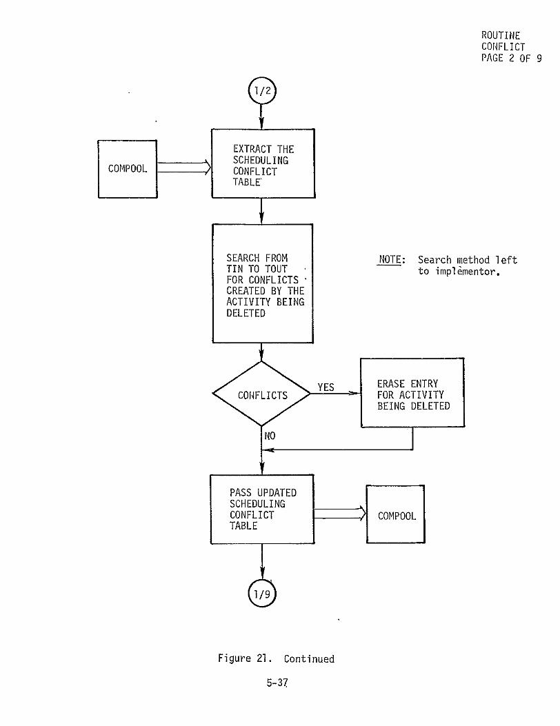
ROUTINE CONFLICT PAGE 2 OF 9
COMPOOL
EXTRACT THE SCHEDULING CONFLICT TABLE'
SEARCH FROM TIN TO TOUT FOR CONFLICTS CREATED BY THE ACTIVITY BEING DELETED
NOTE: Search method left to implhmentor.
YES ERASE ENTRY
C01SLICT FOR ACTIVITY
BEING DELETED
PASS UPDATED
SCHEDULING CONFLICT TABLE
COMPOOL
1/9
Figure 21. Continued
5-37

3/3
ROUTINE CONFLICT PAGE 3 OF 9
EXTRACT THE FILE 1 TEMPOR-AL PARAMETERSCo%,POOL NOIIT(I) 1=1,NOI TIM(I,L)
I=I,NOI L=1,2
SET I=1
KSCHED =IT(1)
Q-3 EXTRACT JSCHED
COMPOOL NN(K) K=KSCHED FROM FILE 1
Figure 21. Continued
5-38

ROUTINE CONFLICT PAGE 4 OF 9
TIN<TIM(I,2)<TOuT YES 3/3
NO
T.IMCI,2)>TOUT
YES
TIM(I,1)<TIN
NO
NO
YES -
2/4
3/3
2/49
Figure 21. Continued
5-39

ROUTINE CONFLICT
PAGE 5 OF 9
1/5
EXTRACT ENTRYCONSUM FOR J-JSCHED
ABLESFROM MASTER ANALYSISCOMPATIBILITY DATA MATRIX
NO_ 1/6
=ONO 2/4
...... YES _
-CONFLICT WARNING .
C--RT
2/54
UPDATE ENTRY
IN SCHEDULING CONFLICT TABLE
CMOL
Figure 21. Continued
5-40

ROUTINE
CONFLICT PAGE 6 OF 9
CMOL
, EXTRACT AT(K,I) K=KSCHED I=I ,5
TINAT(KSCHED,I)<TOUT
YES
NO1/
TIN<AT(KSCHED,2)<TOUT
YES
> SFLAG=I
TIN<AT(KSCHED,3):<TOUT
YES
SFLAG=I2
(
Figure 21. Continued
5-41

ROUTINE CONFLICT PAGE 7 OF 9
TI q<AT (KSCHED,4)<TOUT
YES
SFLAG=2
(
TIKN<AT(KSCHED,3 )<TOr
YES
NOT SFLAG:3
TIN<AT(KSCHED,2)<TOUT
YES,
SFLAG:I3
Figure 21. Continued
5-42

ROUTINE CONFLICT PAGE 8 OF 9
EXTRACT ENTRY YS FROM ARRAY
JCOMP (Ml ,M2,M3) -
M1 =J M2=TFLAG M3=JSCHED
YESYE
Figure 21. Continued
5-43

ROUTINE CONFLICT PAGE 9 OF 9
VTFLAG
2 3
SAT(K4)> NO
4YES
S TFLAG=3
TIN=AT(K,3) TOUT=AT(K,4)
Figure 21. Concluded
5-44

5.8 CONSTRAINT ROUTINE
Description - The CONSTRAINT routine determines if an event being
scheduled or unscheduled affects the rate limit violation for the consumable
subsystems affected by the event. If rate limit violations are created,
the Rate Violation Table for the affected consumable subsystem will be
updated to note the violation and an interactive warning will be provided
to the user on the terminal CRT. Figure 22 presents a skeleton for the
Rate Violation Table.
Interface
I/0 DEVICES - The terminal CRT unit for output only.DATA BASE - COMPOOL for both input and output; and the Consumables
Analysis Data Base for input. ROUTINES CALLING CONSTRAINT - RATE routine. ROUTINES CALLED BY CONSTRAINT - None.
Internal Variables
INR Index for rate table.
ILR Index for rate limit array.
SVFLAG Flag indicating that more than one time point must be considered in checking a time limit:
SVFLAG=O no time point saved I time point saved.
TSAVE If SVFLAG=I, the value of the time point saved.
ISAVE If SVFLAG=l, the index for the time point saved.
INRSV Flag indicating search backwards needed: INRSV=O forward search needed
1 backward search needed.
Input - The CONSTRAINT routine requires the following input data
accessed through the COMPOOL:
TMIN The time to start constraint checking.
TMAX The time to end constraint checking.
CNUM The consumable rate table identifier (see Figure 36 for values of CNUM).
5-45

RATE(CNUM) CNUM=1,9 The rate tables (rate versus time) for each consumable affected by an event.
TABLE(CNUM) CNUM=,9 The rate violation tables for each consumable affected by an event (as defined in Figure 22).
The CONSTRAINT routine requires the following input data from the
Consumables Analysis Data Base:
TXTND(CNUM) CNUM=,9 The time to extend constraint checking.
LIMTYP(CNUM)CNUM=l,9 The type of limits to be checked: 1 a minimum limit value 2 a maximum limit value 3 a min/max bounded limit value 4 a maximum/time duration limit value.
LIMNO(CNUM)CNUM=I,9 The number of limits to be checked.
RLIM(CNUM,I)CNUM=I,9 The value of the rate limit to be checked. I=I,LIMNO
TLIM(CNUM,I)CNUM=l,9 The time duration for RLIM(CNUM,I). I=I,LIMNO
Processing - The flow diagram of the CONSTRAINT routine is presented
in Figure 23.
Output - The CONSTRAINT routine transmits the following data through
the COMPOOL:
TABLE(CNUM) CNUM=I,9 The rate violation tables for each consumable affected by an event (as defined in Figure 22).
If a rate limit violation occurs, the following will be displayed
to the user on the terminal CRT unit:
WARNING Rate limit violation created. See Rate Violation Table (CNUM) for details.
5-46

RATE VIOLATION TABLE FOR CNUM
MISSION ID: RUN MODE:
TIME OF RATE AT LIMIT LIMIT ITEM VIOLATION VIOLATION RATE - TIME
1
2
n
NOTE: CNUM = the consumable rate table identifier (see Figure 36 for the value of CNUM)
Figure 22. The Rate Violation Table Skeleton

ROUTINECONSTRAINTPAGE 1 OF 7
1:ENTERD
COMPOOL
EXTRACT
TMIN,TMAX,CNUM
CONSUM-
ABLES ANALYSISDATA BASE
2 EXTRACT hI TXTND(CNUM)
TMAX=
TMAX+ TXTND (CNUM)
COMPOOL
I SEARCH
RATE VIOLATION TABLE (CNUM)
/ AND DELETE ENTRIES BETW4EEN TMIN AND TMAX)
NOTE: Search method left to implementor.
Figure 23. Flow Diagram for the CONSTRAINT Routine
5-48

ROUTINE CONSTRAINT PAGE 2 OF 7
CONSUM-
DATA BASE
A
EXTRACT LIMTYP(CNUM),LIMNO(CNUM), RLIM(CNUM, I), TLIM(CNUM,I)
I=I,LIMNO
INR=l INRSV=O
2/2
SVFLAG=O
COMPOOL
SEARCH RATE(CNUM) TABLE BETWEEN TMIN AND TMCAX FOR PRATE(INR) AT TIME(INR)
NOTE: Search method left to implementor.
LITP3 YES _e
Figure 23. Continued
5-49

ROUTINE CONSTRAINT PAGE 3 OF 7
11/2
I .2 3
ONO !RATE(INR RL.IM(CNUM,INR)
YES'
RA TI R>R LI(CN M,I R)YES
23. ContinuedFigure
5-O0

2/4
ROUTINE CONSTRAINT PAGE 4 OF 7
ILR=1
RATE(INR)RLIM(CNUMILR)N
YES
1/Y ESOILR=LIMN
ILR= ILR+1
Figure 23. Continued
5-51

ROUTINE
CONSTRAINT PAGE 5 OF 7
COMPOOL
YESDTR=
tope0ti orm
T: Search method left
to implementor.
1/5
E /NSIEINR=1
RATE(CNUM)SEARCH SEARCHRATE(CNUM) TABLE FROMITABLE FROM TIME(INR) FORTIME(INR) FOR1
AT:iRATE(INR-1)RATE(INR+I) TIME(INR-I)AT TIME(INR+I)'
INR=
INRSV= 1 = DTR
TIME(INR+I)-, TIME(INR)
YES ILR=
ILRLLR+1I No N
Figure 23. Continued
5-52

ROUTINE CONSTRAINT PAGE 6 OF 7
DTR>TL~rICCNUM,ILR-1)YE1/
NO
RATE(INR+1)>RLIM(CNUM,ILR-1) NO 2
YES
SVFLA~lNOTSAVE=
LAG=ITIME(INR) J ISAVE=IN R
YES
INR= INR+l
Figure 23. Continued
5-53

ROUTINE
CONSTRAINT
PAGE 7 OF 7'
WARNING
I MAKE ENTRY
IN RATE
VIOLATION COMPOOL TABLE(CNUM)
SVF AGlYESTIME(INR): TSAVE
NO
INRO
INR+I RETURN
Figure 23. Concluded
5-54

5.9 CONSUM HISTORY ROUTINE
Description - The CONSUM HISTORY routine prepares the consumables
versus time data for display or storage in the Flight Data Files. The mech
anization of this process and the display formats will be defined at time
of implementation.
'Interface
I/0 DEVICES - Terminal KEYBOARD and CRT units. DATA BASE - COMPOOL for both input and output.ROUTINES CALLING CONSUM-HISTORY - OUTPUT routine. ROUTINES CALLED BY CONSUM HISTORY - None.
Internal Variables - None.
Input - Will be defined during implementation.
Processing - The CONSUM HISTORY routine is an information management
type routine used to prepare the results of consumables analysis for
display and/or storage. No flow diagram is necessary.
Output - Will be defined during implementation.
5-55

5.10 CONSUM QUANTITIES ROUTINE
Description - The CONSUM QUANTITIES routine calculates the amount
used and end-of-mission reserves for each consumable subsystem and pre
pares the data for display. The mechanization of this process and the
display formats will be defined at the time of implementation.
Interface
I/0 DEVICES - None. DATA BASE - COMPOOL for both input and output. ROUTINES CALLING CONSUM QUANTITIES - OUTPUT routine. ROUTINES CALLED BY CONSUM QUANTITIES - None.
Internal Variables - None.
Input - Will be defined during implementation.
Processing - The CONSUM QUANTITIES routine is an information manage
ment type of routine used to prepare the results of consumables analysis
for display. No flow diagram is necessary.
Output - Will be defined during implementation.
5-56
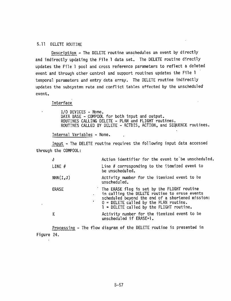
5.11 DELETE ROUTINE
Description - The DELETE routine unschedules an event by directly
and indirectly updating the File 1 data set. The DELETE routine directly
updates the File 1 pool and cross reference parameters to reflect a deleted
event and through other control and support routines updates the File 1
temporal parameters and entry data array. The DELETE routine indirectly
updates the subsystem rate and conflict tables affected by the unscheduled'
event.
Interface
I/0 DEVICES - None. DATA BASE - iCOMPOOL for both input and output. ROUTINES CALLING DELETE - PLAN and FLIGHT routines. ROUTINES CALLED BY DELETE - ACTDIS, ACTION, and SEQUENCE routines.
Internal Variables - None.
Input - The DELETE routine requires the following input data accessed
through the COMPOOL:
3 Action identifier for the event to'be unscheduled.
LINE # Line # corresponding to the itemized event to be unscheduled.
NNN(I,J) Activity number for the itemized event to be unscheduled.
ERASE The ERASE flag is set by the FLIGHT routine in calling the DELETE routine to erase events scheduled beyond the end of a shortened mission: 0 = DELETE called by the PLAN routine. I = DELETE called by the FLIGHT routine.
K Activity number for the itemized event to be unscheduled if ERASE=l.
Processing - The flow diagram of the DELETE routine is presented in
Figure 24.
5-57

Output - The DELETE routine transmits the following data through
the COMPOOL:
K Activity number for the itemized event to
be unscheduled.
M Pool counter credited for a delete.
NM(I)=K I=M The unscheduled activity number is placed in the available activity array.
NNN(I,J)=O I=LINE # The specified unscheduled event~activity number J=J cross reference is removed.
IN(J) The number of ACTION J items scheduled is reduced.
NN(K)=O The specified unscheduled activity-action cross reference is removed.
ACTION MODE=DELETE Mode flag for the ACTION routine to unschedule an event.
5-58
ROUTINE DELETE PAGE 1 OF 3
ENE
COMPOOL EXTRACT ERASE FLAG
ERSE] E EXTRACT
ACTIVITY #K C1PO
COMPOOL
CALL ACTDI.S FOR ACTION IDENTIFIED J
COMPOOL . EXTRACT ACTION IDENTIFIER J
COMPOOL 'EXTRACTLINE # ENTERED ON DISPLAY X
Figure 24. Flow Diagram for the DELETE Routine
5-59

ROUTINE DELETE PAGE 2 OF 3
© EXTRACT1ACTIVITY K FROM4 FILE I
.IMPOOL UATA
_.K=INNN(LINE #,J)
2/2
SET POOL PARAMETERS IN FILE 1 DATA
M=M+I NM(M)=K
4 SET ACTION
MODE = TO DELETE
PASS ACTION MODE, ACTIVITY #K, COMPOOL AND POOL
ACTIONIOPARAMETERS CAL
CALL ACTION
TO DELETE ENTRY DATA ARRAY, AT(K,I) I=1,5 FOR ACTIVITY K FROM THE FILE 1 DATA; TO DELETE ACTIVITY K EFFECTS FROM THE RATE AND CONFLICT TABLES
Figure 24. Continued
5-60

ROUTINE DELETE
PAGE 3 OF 3
CALL SEQUENCE TO DELETE ACTIVITY K FILE 1 SCHEDULING DATA
RESET CROSS REFERENCE PARAMETERS IN
FILE 1 DATA
NNN(IN(J),J)=O IN(J)=IN(J)-1 NN(K)=O
REFERECEPOOLPARAMETERS
CRETURN
Figure 24. Concluded
5-61

5.12 DISPLAY ROUTINE
Description - The DISPLAY routine is a universal routine to execute
the interactive User Interface and the read only Output displays on the CRT
unit.
Interfaces
I/0 DEVICES - CRT unit. DATA BASE - COMPOOL for both input and output. ROUTINES CALLING DISPLAY - PLAN and OUTPUT routines. ROUTINES CALLED BY DISPLAY - none.
Internal Variables - None.
Input - The DISPLAY routine requires the following input data and
display skeletons accessed through the COMPOOL:
X Display variable X = to the Identifier for the display to be executed (see Tables I and II for specific display identifiers)
FLAG(X) Display skeleton flag for display X
SKELETON(X) Display skeleton for display X
DATA(X) Data set for display X
MOD(X) Mod flag for display X.
Processing - The flow diagram of the DISPLAY routine is presented
in Figure 25.
Output - The DISPLAY routine transmits the following data through the
COMPOOL:
MAX(X) The maximum lines on display X.
The DISPLAY routine provides the following to the user through
the CRT display unit:
SKELETON(X) Display skeleton for display X DATA(X) Data set for display X MOD(X) Mod flag for display X.
5-62

ENTER
ROUTINE DISPLAY
PAGE 1 OF 2
COPOLEXTRACT
Fi 5 Fw D DISPLAY VARIABLE
R
COMP-O COMPO[
1
EXTRACT DISPLAY SKELETON FLAG FOR DISPLAYX
SET
COMPOOL EXTRACT SKELETON
FOR DISPLAY X
Figure 25. Flow Diagram for the DISPLAY Routine
5-63

ROUTINE DISPLAY
1/2 PAGE 2 OF 2
COMPOOL EXTRACT DATA FOR DISPLAY X
COMPOOL EXThACT MOD FLAG FOR DISPLAY X
EXECUTECT DISPLAYX
PASS MAX LINES
ON DISPLAY XCOPO OPL
CRETURN
Figure 25. Concluded
5-64

5.13' EVENT CHART ROUTINE
Description - The EVENT CHART routine can be called in either the Event Mode or Active Mode to prepare the event chart data for display.
These data include the influence variables, factors, consumable usage for
each subsystem, and consumable kit requirements. The mechanization of this
process and the display formats are will be defined at time of implementation.
Interface
I/0 DEVICES - none. DATA BASE - COMPOOL for both input and output. ROUTINES CALLING EVENT CHART - OUTPUT routine. ROUTINES CALLED BY EVENT CHART - none.
Internal Variables - None.
Input - Will be defined during implementation.
Processing - A functional flow diagram of the EVENT CHART routine is
presented in Figure 26.
Output - Will be defined during implementation.
5-65

ROUTINE EVENT CHART PAGE 1 OF 2ENTER
EXTRACTRUN MODE
R MOD
F g r 2
EXTRACTFILE I
FhEVENDATA R COMPOOL
COPPOOLFATR
COMPOOL . •
EXTRACTINFLUENCE VARIABLES VALUES
RECONSTRUCTINFLUENCE VARIABLES VALUES
COMPODL EXTRACT FACTORS
CALCULATE CONSUMABLES FOR EACH SUBSYSTEM
Figure 26. Flow Diagram for the EVENT CHART Routine
5-66

6Th ROUTINE EVENT CHART PAGE 2 OF 2
COMPOOL
EXTRACT STANDARD CONFIGURATION FOR EACH SUBSYSTEM
CALCULATE DELTA
CONSUMABLES FOR EACH SUBSYSTEM
EXTRACT KIT -COMPOOL ICONFIGURATION
CPO • FOR EACH
SUBSYTEM
CALCULATE KIT REQUIREMENTS
STORE ALL CALCULATED DATA
COMPOOL
CRETURN
Figure 26. Concluded
5-67

5.14 FILE ONE ROUTINE
Description - The FILE ONE routine prepares the flight File 1
data set for use by the Mission Planning Processor.
Interface
I/0 DEVICES - Terminal KEYBOARD unit. DATA BASE - Flight Data File for input and the COMPOOL
for output. ROUTINES CALLING FILE ONE'- EXEC routine. ROUTINES CALLED BY FILE ONE - None.
Internal Variables - None.
Input - The FILE ONE routine requires the following data input
through the terminal KEYBOARD unit:
MISSION ID The mission identifier.
The FILE ONE routine requires as input the File 1 data set stored
for the identified mission. Table III defines the File 1 data set
parameters.
Processing - The flow diagram of the FILE ONE routine is presented
in Figure 27.
Output - The FILE ONE routine transmits the File 1 data set for the
identified mission through the COMPOOL. Table III defines the File 1 data
set parameters.
5-68

Table III. File 1 Data Set
Parameter Type
Parameter Name
Parameter Format Parameter Description
Pool N Fixed Entry counter
Pool M Fixed Pool Counter
Pool NM(I) I=I,M Available activity number array
Temporal NOI Fixed Number of entries in sequence array
Temporal IT(I) 1=1,NOI Sequence array of activities
Temporal TIM(I,L) I=I,NOI L=1,2
Start and end times of activities L=l Minimum start time of activity IT(I) 2 Maximum end time of activity IT(I)
, Cross Ref. IN(J) J=1,23 Number of ACTION J items scheduled
Cross Ref. NN(K)=J K=I,N Activity-Action cross reference (i.e., activity number K is an ACTION J)
Cross Ref. NNN(I,J)=K I=I,IN(J) J=1,23
Event-Activity cross reference (i.e., activity number for the Ith event of ACTION J scheduled)
Entry AT(K,I) 1=1,5 Entry data array for activity K I=I prep start time 2 reference start time 3 reference stop time 4 post end time 5 special parameter, a function of ACTION Identifier J:
J=1,2,4,6, or 7; AT(K,5)=AV J=9,10,20,21, or 22; AT(K,5)=Number of crew

Table III. - Continued
Parameter Parameter Parameter Type Name Format Parameter Description
Data BPT(I) 1=1,11 Block phase times 1=1 prelaunch start 2 prelaunch stop/ascent start 3 liftoff 4 MECO 5 ETS 6 OMS ignition/on-orbit start 7 on-orbit stop/deorbit start 8 deorbit burn ignition 9 deorbit stop/entry start
10 rollout 11 entry/land stop
Data BPDT(I) I=1,13 Block phase delta times
1=1 prelaunch2 ascent 3 GSE-liftoff 4 liftoff-MECO 5 MECO-ETS 6 ETS-OMS ignition 7 dn-orbit 8 deorbit 9 prep-burn
10 burn to entry interface 11 entry/land12 entry interface-rollout 13 rollout-GSE

Table III. - Concluded
Parameter Parameter Parameter Type Name Format Parameter Description
Data CONFG(I) I=1,11 Mission Configuration Data I=] crew size 2 number of EPS consumables kits 3 number of OMS consumables kits 4 number of EPS (LIOH) kits 5 orbital inclination 6 day of launch 7 month of launch 8 year of launch 9 gross weight at liftoff
10 launch site ID 11 landing site ID

ROUTINE 'FILEONE
PAGE 1 OF 1ENTER
KEY-BOAR
ENTER MISSION ID
READ FILE 1 FOR MISSION IDENTIFIED
STORE FILE 1I
DATA IN COMPOOL
COMPOOL
CRETURND
Figure 27. Flow Diagram for the FILE ONE Routine
5-72

5.15. FILE STORE ROUTINE
Description - The FILE STORE routine,transfers the results of the Mission Planning Processor to permanent storage in the Flight Data File.
The user has the option of selecting the type of data to be stored.
Interface
I/0 DEVICES - None. DATA BASE - COMPOOL for input and the Flight Data File for
output. ROUTINES CALLING FILE STORE - OUTPUT routine. ROUTINES CALLED BY FILE STORE - None.
Internal Variables - None.
Input - The FILE STORE routine requires the following input data
accessed through COMPOOL:
Y Store variable Y Y = I store File 1 data set
2 store Files 1 and 2 data sets 3 store Files 1, 2, and 3 data sets 4 store File 0 data set
MISSION ID Mission identifier
DATA(O) File 0 data set (parameters are defined in Volume IV)
DATA(1) File 1 data set (parameters are defined in Table III)
DATA(2) File 2 data set (parameters are defined in Volume IV)
DATA(3) File 3 data set (parameters are defined in
Volume IV)
Processing - No flow diagram is necessary.'
Output - The FILE STORE routine transfers the following data to
the Flight Data File for the mission identified:
DATA(O) File 0 data set (paremeters are defined in Volume IV)
DATA(l) File 1 data set (parameters are defined in Table III)
DATA(2) File 2 data set (parameters are defined in Volume IV)
DATA(3) File 3 data set (parameters are defined in Volume IV).
5-73

5.16 FILE ZERO ROUTINE
Description - The FILE ZERO routine prepares the flight File 0
data set for use by the Mission Planning Processor. The File 0 data set
contains event chart related data to reinitialize processing in the Event
Mode only.
Interface
I/0 DEVICES - Terminal KEYBOARD unit. DATA BASE - Flight Data File for input and the COMPOOL for
output. ROUTINES CALLING FILE ZERO'- IV INPUT routine. ROUTINES CALLED BY FILE ZERO - none.
Internal Variables - None.
Input - The FILE ZERO routine requires the following data input
through the terminal KEYBOARD unit:
MISSION ID The mission identifier.
The FILE ZERO routine requires as input the File 0 data set stored
for the identified mission. The File 0 data set is defined in Volume IV-
Processing - The flow diagram of the FILE ZERO routine is presented
in Figure 28.
Output - The FILE ZERO routine transmits the File 0 data set for the
The File 0 data set is defined inidentified mission through the COMPOOL.
Volume IV.
5-74

ROUTINE FILE ZERO PAGE I OF 1
ENTER
ENTER
KEY-DMISSION,
FIGure 28EXTRACT FILE 0 EVENT DATADATA I FOR MISSION
FIEIDENTIFIED
PASS FILE 0 COMO! COPODATA
Figure 28. Flow Diagram for the FILE ZERO Routine
5-75

5.17 FLIGHT ROUTINE
Description - The FLIGHT routine updates all flight block parameters and common block rates if any phase block time ischanged in the active run
mode. If the on-orbit phase is shortened, the FLIGHT routine will remove
the affects of activities scheduled beyond the new deorbit time.
Interface
I/0 DEVICES - Nonfeo DATA BASE - COMPOOL for both input and output. ROUTINES CALLING FLIGHT - PLAN routine. ROUTINES CALLED BY FLIGHT - SPECIAL, RATE, and DELETE routines.
Internal Variables - None.
Input - The FLIGHT routine requires the following input accessed
through COMPOOL:
APT(I) I=1,11 Block phase time changes I= prelaunch start 2 prelaunch stop/ascent start 3 liftoff 4 MECO 5 ETS 6 OMS ignition/on-orbit start 7 on-orbit stop/deorbit start 8 deorbit burn ignition 9 deorbit stop/entry'start
10 rollout 11 'entry/land stop
APTD(I) I=1,13 Block phase delta time changes I=I prelaunch 2 ascent 3 GSE-liftoff 4 lift-off 5 MECO-ETS 6 ETS-OMS ignition 7 on-orbit 8 deorbit 9 prep-burn
10 burn to entry interface 11 entry/land 12 entry interface-rollout 13 rollout-GSE
5-76

J The ACTION identifier required by the common block to be scheduled or unscheduled (see Table I for the values of J).
BPT(7) The deorbit phase start time for the File 1 data set block phase time array.
NOI Number of entries in sequence array.
IT(I) I=l,NOI Sequence array of activities.
TIM(I,L) I=I,NOI Start and end times of activities: L=1,2 L=l minimum start time of activity IT(I)
2 maximum end time of activity IT(I).
IN(J) J=1,23 Number of ACTION J items scheduled.
NN(K)=J K=I,N Activity-Action cross reference.
NNN(I,J)=K I=I,IN(J) Event-Activity cross reference. J=1,23
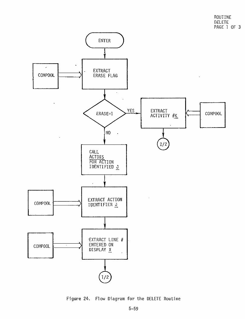
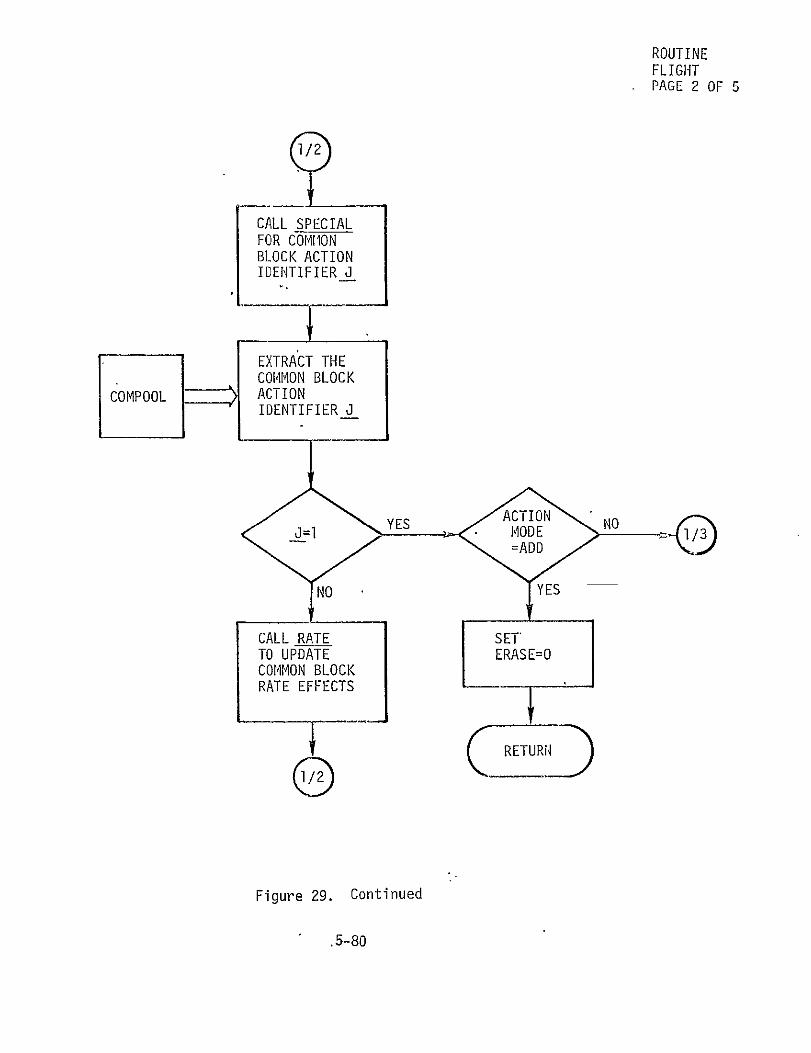
Processing - The flow diagram of the FLIGHT routine is presented in
Figure 29.
Output The FLIGHT routine transmits the following data through the
COMPOOL:
BPT(I) I=1,11 Block phase times =1 prelaunch start 2 prelaunch stop/ascent start 3 liftoff 4 MECO 5 ETS 6 OMS ignition/on-orbit start 7 on-orbit stop/deorbit start 8 deorbit burn ignition 9 deorbit stop/entry start
10 rollout 11 entry/land stop
BPTD(I) I=1,13 Block phase delta times I=I prelaunch 2 ascent 3 GSE-liftoff 4 liftoff-MECO 5 MECO-ETS 6 ETS-OMS ignition 7 on-orbit 8 deorbit 9 prep-burn
10 burn to entry interface 11 entry/land 12 entry interface-rollout 13 rollout-GSE
5-77

The ACTION identifier required by the event or common block to be scheduled or unscheduled (see Table I for the values of J).
K Activity number for the event to be unscheduled.
ACTION MODE Mode flag for theACTION routine to schedule or unschedule an event: ADD = schedule an event DELETE = unschedule an event.
ERASE The ERASE flag is set by the FLIGHT routine in calling the DELETE routine to erase events scheduled beyond the end of a shortened mission: 0 = DELETE called by the PLAN routine 1 = DELETE called by the FLIGHT routine.
5-78

ROUTINE FLIGHT PAGE 1 OF 5
ENTER
EXTRACT CHANGES TO BLOCK PHASE
COMPOOLTI1ES APT()CPOL1=1,1 OR CHANGES
TO BLOCK PHASE DELTA TIMES APTD(I) I=1,13
CALCULATE THE UPDATED BPT(I) I=1,11 AND BPTD(I) 1=1,12 FILE 1 DATA ARRAYS
SET ACTION MODE=DELETE AND ACTION IDENTIFIER J=O
PASS ACTION MODE AND COMPOOL ACTION IDENTIFIER
- Figure 29. Flow Diagram for the FLIGHT Routine
5-79
ROUTINE FLIGHT PAGE 2 OF 5
1/2
CALL SPECIAL FOR COMHON BLOCK ACTION IDENTIFIER J
EXTRACT THE
COPOLACTION COMMON BLOCK
IDENTIFIER J
14NN YYES
CALL RATE ST TO UPDATE ERASEzO COMMON BLOCK RATE EFFECTS I
I-~ (~_ETURrD
Figure 29. Continued
.5-80

ROUTINE FLIGHT PAGE 3 OF 5
EXTRACT THE DEORBIT TIM4E BPT(7) FROM
COMPOOL FILE 1,DATA ARRAY
1/4CO 00
PASS UACTEDN
DE =ADD Y AND ACTION IDENTIFIER J=0
ACIIDENTIFIER
ANDDEAND1)1COMPOOL
Figure 29. Continued
5-81
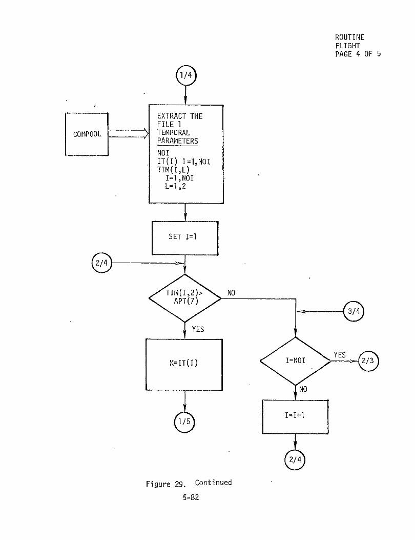
ROUTINE FLIGHT
PAGE 4 OF 5
-V-EXTRACT THE FILE 1
COMPOOL TEMPORAL PARAMETERS
NOIIT(I) I=1,NOI TIM(I,L)
I=I,NOI L=1,2
SET I= 1
2/4
K=IT(1) I=NOI -
•=1401
Figure 29. Continued
5-82

ROUTINE
FLIGHT PAGE 5 OF 5
EXTRACT THE FILE 1 CROSS
COMPOOL REFERENCE PARAMETERS
=NN(K) j
ERAS E=1
PASS ERASE, U, AND K COMPOOL
CALL DELETE TO ERASE ALL ACTIVITIES PAST NEW DEORBIT TIME
4'
Figure 29. Concluded
5-83

5.18 INITIAL ROUTINE
Description - If the data option entered through the EXEC routine
is set to Initial, the INITIAL routine will develop the File I data set
for use by the Mission Planning Processor. The data set is constructed
from the mission configuration data input through the terminal keyboard
unit and the mission skeleton data from the Consumables Analysis Data Base.
Interface
I/0 DEVICES - Terminal KEYBOARD unit. DATA BASE - Consumables Analysis Data Base for input and COMPOOL
for both input and output. ROUTINES CALLING INITIAL - EXEC routine. ROUTINES CALLED BY INITIAL - DISPLAY routine.
Internal Variables - None.
Input - The INITIAL routine requires the following data intput through
the terminal KEYBOARD unit:
MISSION ID The mission identifier
CONFG(I) I=1,11 The configuration data for the identifiedcmission. (see Table III for definition of parameters.)
The INITIAL routine also requires the following input data accessed
through the COMPOOL:
TABLE The Active Mode Display Cross Reference Table (as defined in Table I).
Processing - The flow diagram of the INITIAL routine is presented
in Figure 30.
Output - The INITIAL routine-transmits the following data through
the COMPOOL:
X Display variable X = to the identifier for the configuration display (see Table I for ID values).
The INITIAL routine also transmits the mission configuration data
restructured to the File 1 data set format through the COMPOOL. Table III
defines the File 1 data set parameters.
5-84

ROUTINE INITIAL PAGE 1 OF 2 ENTER,.
BOARD MISSION IDENTIFIER
CONSUM-
ABLES ANALYSIS DATA BASE
.
EXTRACT
SKELETON "DATA FOR MISSION IDENTIFIED,
COMPOOLMODE EXTRACT ACTIVEDISPLAY
CROSS REFERENCE TABLE
SET DISPLAY VARIABLE X= TO ID FOR CONFIGURATION DISPLAY
Figure 30. Flow Diagram for the INITIAL Routine
5-85

ROUTINE 1/2 INITIAL
PAGE 2 OF 2
CALL DISPLAY TO EXECUTE CONFIGURATION
DISPLAY
KE;Y- ACCEPT
KEY- CONFG(I) BOARD y=
REFORMAT CONFIGURATION DATA TO FILE 1 FORMAT-
DATACOOO
RETURN
Figure 30. Concluded
5-86

5.19 IV INPUT ROUTINE
Description - When the Mission Planning Processor is run in the Event
Mode, the IVINPUT routine permits the user to input the influence variables used to generate an event chart. The user has the option to input original
influence variable values, use previously stored influence variable values
from the File 0 data set, or modify the influence variable values entered.
Interface
I/0 DEVICES - Terminal KEYBOARD unit. DATA BASE - COMPOOL for input and output. ROUTINES CALLING IV INPUT 4 EXEC routine. ROUTINES CALLED BY IV INPUT - FILE ZERO and DISPLAY routines.
Internal Variables - None.
Input - The IV INPUT routine requires the following data input through
the terminal KEYBOARD unit:
MODE OPTION IV INPUT operation mode; = INITIAL the influence variable values input
through terminal KEYBOARD unit = EDIT the influence variable values input
from the File 0 data set
VALUE(IV) The influence Variable value.
The IV INPUT routine also requires the following input data accessed
through the COMPOOL:
TABLE Event Mode Display Cross Reference Table .(definition is TBD)
DATA(O) The File 0 data set (parameters are defined in Volume IV).
Processing - The flow diagram of the IV INPUT routine is presented
in Figure 31.
Output - The IV INPUT routine transmits the following data through
the COMPOOL:
X The display variable X = to the identifier for the influence variable display (see Table I for identifier)
DATA(O) The File 0 data set (parameters are defined in Volume IV).
5-87

ROUTINE IV INPUT PAGE 1 OF 2
ENTER
KEY- KEY-'ENTERMODE OPTION
~CALL
MOEYS
OPTION
EDIT
FILE ZERO
FOR PREVIOUS
EVENT DATA
EXTRACTINFLUENCE VARIABLES
COMPOOL
EXTRACT EVENT
COMPOOL MODE DISPLAY CROSS REFERENCE TABLE
SET DISPLAY VARIABLE X = TOID FOR INFLUENCE VARIABLE DISPLAY
Figure 31. Flow Diagram for the IV INPUT Routine
5-88

ROUTINE IV INPUT
/PAGE 2 OF 2
PASS DISPLAY COMPOOL VARIABLE X
CALL DISPLAY TO EXECUTE INFLUENCE VARIABLE DISPLAY
-I
INFLUEN CE VARIABLE
KE-VALUE OR BOARDEXIT
PASS UPDATED INFLUENCE COMPOOL VARIABLES
Figure 31. Concluded
5-89

5.20 LINECK ROUTINE
Description - The LINECK routine determines the progression through the user interface displays. The line number entered on the active display
is queried to determine if that display is to remain active during the next Mission Planning Processor activity or if the next display in the progres
sion is required.
Interface
I/0 DEVICES - Terminal KEYBOARD unit. DATA BASE - COMPOOL for both input and output. ROUTINES CALLING LINECK - PLAN routine. ROUTINES CALLED BY LINECK - none.
Internal Variables - None.
Input - The LINECK routine requires the following data input through
the terminal KEYBOARD unit:
LINE # The line number corresponding to the display selected on the display active on the CRT unit.
The LINECK routine requires the following input data accessed through
the COMPOOL:
X Display variable X = to the identifier of the active display (see Table I for specific display identifiers)
MAX(X) The maximum lines on display X.
Processing - The flow diagram of the LINECK routine is presented
in Figure 32.
Output - The LINECK routine transmits the following data through
COMPOOL:
LINE # The line number corresponding to the display selected on the display active on the CRT unit.
CHECK(X) The display check flag set if the next display in the progression is required.
5-90

ROUTINE LINECK PAGE 1 OF 2
ENTER
ENTER
3LINE # BOARD [FRODISPLAY X
ON CRT
OMPOL ) EXTRACT,COMPOOLDISPLAY
VARIABLE X
, EXTRACT MAX
COMPOOL LINES ON DISPLAYX
COMPARE LINE # ENTERED TO MAX LINES
.Figure 32. Flow Diagram for the LINECK Routine
5-91

ROUTINE LINECK PAGE 2 OF 2
MAX YES SET DISPLAY CHECK.FLAG
PASS DISPLAY CHECK FLAG
COMPOOL
PASS LINE # ENTERED'
COMPOOL
Figure 32. Concluded
5-92

5.21 OUTPUT ROUTINE
Description - The OUTPUT routine provides the user with the option
to display and/or store selected data generated by the Mission Planning
Processor. In the Event Mode, only the Event Chart displays can be executed.
In the Active Mode, all Output displays, including the Event Chart displays,
can be executed. The Output displays are listed in Table II. The user
may select not to store any data. However, the user will be warned of that
selection and asked for a confirmation to prevent inadvertent loss of data.
Interface
I/0 DEVICES - The terminal KEYBOARD and CRT units. DATA BASE - COMPOOL for both input and output. ROUTINES CALLING OUTPUT - EXEC routine. ROUTINES CALLED BY OUTPUT - EVENT CHART, TIMELINE, CONSUM HISTORY,
CONSUM RESERVES, DISPLAY, and FILE STORE routines.
Internal Variables
W Output variable W = to the display option entered through the terminal KEYBOARD unit.
Input - The OUTPUT routine requires the following data input through
the terminal KEYBOARD unit:
DISPLAY OPTION Display option to select data to be displayed; = 0 no display, return 1 no display, store data only 2 display the CONFLICT TABLE 3, display the EVENT CHART 4 display the TIMELINE 5 display the CONSUMABLES VS TIME 6 display the CONSUMABLES QUANTITIES
STORE OPTION Store option to select data set to be stored; = 0 store nothing, return I store File 1 data set 2 store Files 1 and 2 data sets 3 store Files 1, 2, and 3 data sets 4 store File 0 data set
The OUTPUT routine also requires the following input data accessed
through the COMPOOL:
RUN MODE Mission Planning Processor operation mode; EVENT computer aided event chart generation
only ACTIVE Interactive mission planning
5-93

TABLE The output Display Cross Reference Table (asdefined inTable II).
Processing - The flow diagram of the OUTPUT routine ispresented
in Figure 33.
Output - The OUTPUT routine presents the following warning displays
through the terminal CRT unit:
EVENT CHART ONLY Displayed ifthe RUN MODE = EVENT and a different output display is requested
NO FILE GENERATED Displayed when STORE OPTION = 0 is entered the first time.
The OUTPUT routine also transmits the following data through the
COMPOOL':
X Display variable X = to the identifier of the requested output display (see Table I for specific identifiers).
Y Store variable Y = to store option = 0 store nothing, return 1 5tore File 1 data set 2 store Files 1 and 2 data sets 3 store Files 1, 2,and 3 data sets 4 store File 0 data set
5-94

ENTER ROUTINE OUTPUTPAGE 1 OF"4
KEY-BOARD
Ai
ENTER DISPLAYOPTION
SET OUTPUT VARIABLE W
EQUAL TO DISPLAY OPTION
0 = NO DISPLAY 3 = EVENT CHART RETURN 4 = TIMELINE
I = NO DISPLAY 5 = CONSUMABLES STORE DATA VERSUS TIME
2 = CONFLICT 6 = END OF TABLE MISSION
QUANTITIES
COMPOOL EXTRACT RUN MODE
YES
• J "
1DISPLAY
Figure 33. Flow Diagram for the OUTPUT Routine
5-95

ROUTINE 'OUTPUT
1/2 PAGE 2 OF 4
NO
IMELIN =HIYSR 1UATI3E
NO
Figure 33. Continued
5-96

ROUTINE 1OUTPUT
PAGE 3 OF 4
_MOO EXTRACT OOTPUT DISPLAY CROSS REFERENCE. TABLE
SET DISPLAY VARIABLE X ='TO ID FOR OUTPUTDISPLA.Y AS A FUNCTION OF W
2 = CONFLICT TABLE 3 = EVENT CHART 4 = TIMELINE 5 = CONSUMABLES
HISTORY 6 = CONSUMABLES
QUANTITIES
PASS DISPLAY VARIABLE X
OPL
CALL DISPLAY WEXECUTE
OUTPUT DISPLAY
S Figure 33. Continued
5-97

ROUTINE OUTPUT PAGE 4 OF 4
ABOARDSTORE OPTION
2/4
SET STORE VARI-ABLE Y = TO STORE-OPTION
0 = NO STORE I = FILE I 2 = FILE 1+2 3 = FILE 1+2+3 4 = FILE O(EVENT)
YES WARNING CRT NO FILE-'T G-
VARIABLE Y
RE-ENTER KY
STOREcBOARD OPTION3
FILE STORE TOTST-ORE DATA FILE
STORE YES
OPTION 3/
C5-98RETURN 2/
Figure 33. Concluded
5-98

5.22 PLAN ROUTINE
Description - The PLAN routine provides the Mission Planning Processor
user with the capability to interactively schedule, modify, or unschedule
consumable related mission events. The PLAN routine controls the progres
sion through a series of Interactive Displays listed in Table I. Through
terminal KEYBOARD unit entry to these displays, the user requests mission
planning tasks. The PLAN routine acts as a middle manager calling on other
control and support and computational routines to perform the tasks by
manipulating the File 1 data set and immediately feeding back the results
of the tasks to the user through the same Interactive Displays. The user
will also be immediately informed if the results created any scheduling
conflicts or consumable rate limit violations. Also, the conflicts and/or
violations will be noted in CONFLICT TABLES for later assessment by the user.
Interface
I/0 DEVICES - Terminal KEYBOARD unit. DATA BASE - COMPOOL for both input and output; and the Consumables
Analysis Data Base for input. ROUTINES CALLING PLAN - EXEC routine. ROUTINES CALLED BY PLAN - DISPLAY, LINECK, FLIGHT, ADD, and
DELETE routines.
Internal Variables
CYCLE If a display sumary is requested, CYCLE is used as a counter to cycle through the particular set of displays requested for execution.
LIMIT Ifa display summary is requested, LIMIT is set to the maximum number of displays in the particular set requested for execution.
Input - The PLAN routine requires the followin'g data input through
the terminal KEYBOARD unit:
5-99

PROCEED If a display summary is requested, the PROCEED instruction will cause the next display in the requested set of displays to be executed.
LINE # = n The line number corresponding to the itemized event on the ACTION display. The value determines the mission planning task requested; - n modify the scheduled event -n unschedule the scheduled event n+l schedule the event n+2 return to the MENU display.
DATA The specific data set required by the ACTION display to perform the tasks requested (specific parameters are a function of the ACTION display being processed as defined in Table IV).
The PLAN routine requires the following input data accessed through
the COMPOOL:
CHECK(X) The display check flag set if the next display inthe progression is required.
LINE # The line number corresponding to the next selected display in the progression.
MAX(X) The maximum lines on display X.
Z The display variable Z = to the identifier of the MENU display being processed (see Table I for ID values).
The PLAN routine requires the following input data from the Consumables
Analysis Data Base:
TABLE The Active Mode Display Cross Reference Table (as defined in Table I).
Processing - The flow diagram of the PLAN routine is presented in
Figure 34.
Output - The PLAN routine transmits the following data through the
COMPOOL:
X The display variable X = to the identifier of the ACTION display being executed (seeTable I for ID values).
5-100
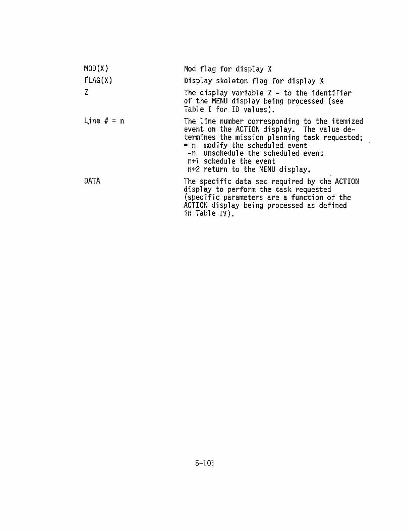
MOD(X) Mod flag for display X
FLAG(X) Display skeleton flag for display X
Z The display variable Z = to the identifier of the MENU display being processed (see Table I for ID values).
Line # = n The line number corresponding to the itemized event on the ACTION display. The value determines the mission planning task requested; - n modify the scheduled event -n unschedule the scheduled event n+l schedule the event n+2 return to the MENU display.
DATA The specific data set required by the ACTION display to perform the task requested (specific parameters are a function of the ACTION display being processed as defined in Table IV).
5-101

Table IV. Input Parameters Required to Schedule/Unschedule an Activity
ACTION ID
1
2
3
4
5
6
7
8
9
10
11
12
13
14
15
16
17
18
19
20
21
22
23
ACTIVITY
OMS MANEUVER
RCS TRANSLATION
ATTITUDE HOLD
RENDEZVOUS
STATION KEEPING
DOCK
UNDOCK
PTC
EVA
IVA
MANIPULATOR OPS
IMU ALIGNMENT
PAYLOAD BAY DOORS
PAYLOAD CONSUMABLES
COMPUTER
TV
DOWNLINK
UPLINK
FUEL CELL PURGE
EAT
SLEEP
WASTE MANAGEMENT'
APU CHECKOUT
INPUT PARAMETERS
REF START, AV
REF START, AV
REF START, REF STOP, ALT, TYPE HOLD
REF START, REF STOP, AV
REF START, REF STOP
REF STOP, AV
REF START, AV
REF START, REF STOP, 'DUTY, PERIOD
REF START, REF STOP, NUMBER OF CREW
REF START, REF STOP, NUMBER OF CREW
REF START, REF STOP
REF START, REF STOP, DUTY, PERIOD
REF START, REF STOP
REF START, REF STOP, DUTY, PERIOD, AND PAYLOAD related data (see Sec. 5.26)
REF START, REF STOP, DUTY, PERIOD
REF START, REF STOP, DUTY, PERIOD
REF START, REF STOP
REF START, REF STOP
REF START, REF STOP, DUTY, PERIOD
REF START, REF STOP, DUTY, PERIOD, NUMBER OF CREW
REF START, REF STOP, DUTY, PERIOD, NUMBER OF CREW
REF START, REF STOP, DUTY, PERIOD
REF START, REF STOP
5-102

ROUTINE PLAN
ENTER PAGE 1 OF 13
CONSUM- IEXTRACT ACTIVE ABLES IMODE DISPLAY ANALYSIS CROSS REFERENCE DATA BASE TABLE
SET DISPLAY VARIABLE X =
TO ID FOR FLIGHT BLOCK DISPLAY
PASS DISPLAYVARIABLEX C
.CALL
DISPLAY F3R FLIGHTBLOCK DISPLAY
CALL LINECK TO DETERMINE
2//2 DISPLAY PROGRESSION
EXTRACT COMPOOL DISPLAY CHECK
FLAG
Figure 34. Flow Diagram for the PLAN Routine
5-103

ROUTINE 1/2 PLAN
PAGE 2 OF 13
CEKFLAG YE ETR
SET
EXTRACT COMPOOL ENTERED
LINE N
SET DISPLAY VARIABLE X = TO ID FOR PHASE BLOCK AS A FUNCTION OF LINE # 2 = ASCENT 3 = ON ORBIT 4 = DEORBIT 5 = ENTRY/LAND
PASS DISPLAY COMPOOL VARIABLE X
S1/3
Figure 34. Continued
5-104

.ROUTINE PLAN PAGE 3 OF 13
CALL DISPLAY TRAPHASE BLOCK DISPLAY
CALL LINECK TO DETERMINE DISPLAY PROGRESSION
EXTRACT COMOOLDISPLAY
CHECK FLAG
CHC LG YES
Figure 34. Continued
5-105

ROUTINE /PLAN
PAGE 4 OF 13
CALL FLIGHT TO CALCULATE FLIGHT BLOCK DATA AND RATES]II
SET IMOD FLAG
PASS MOD FLAG COMPOOk
SIS
SKELETON FLAG FOR DISPLAYX
PASS DISPLAY
SKELETON FLAG COMPOOL FOR DISPLAY X
Figure 34. Continued
5-106
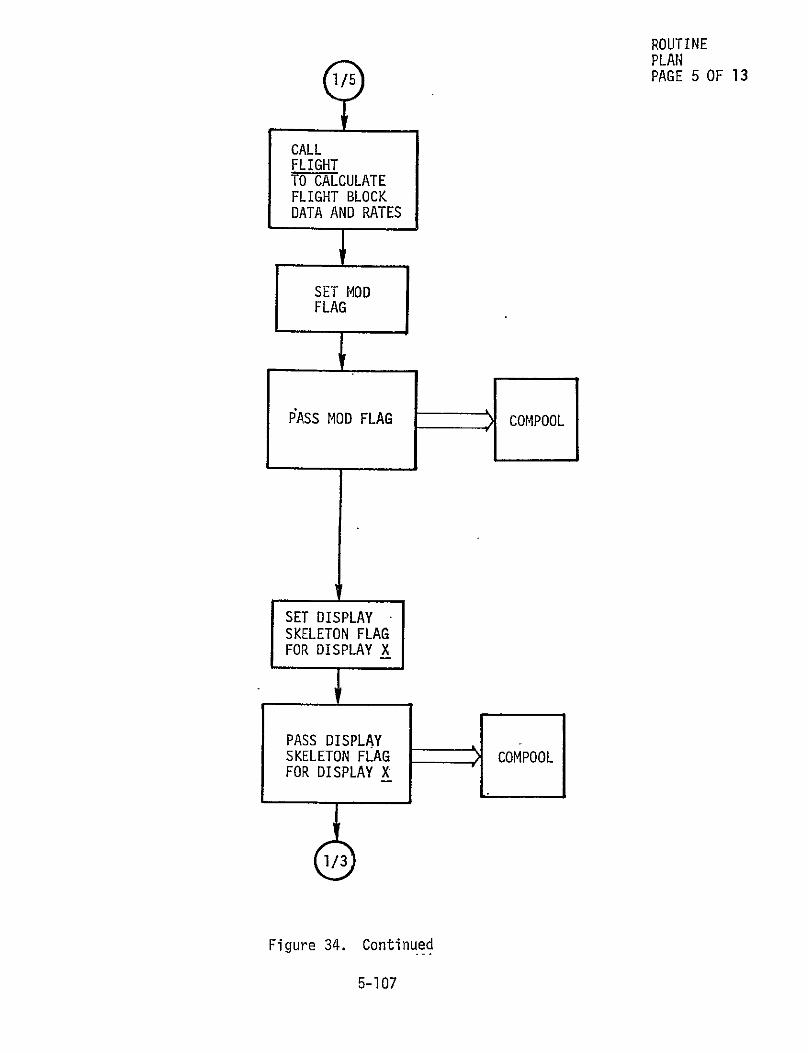
ROUTINE PLAN
/PAGE 5 OF 13
CALL FLIGHT TO CALCULATE FLIGHT BLOCK DATA AND RATES
S SETr MOD
FLAG $
PASS MOD FLAG COMPOOL
SET DISPLAY
SKELETON FLAG FOR DISPLAY X
PASS DISPLAY SKELETON FLAG COMPOOL FOR DISPLAY X
Figure 34. Continued
5-107

~PLAN ROUTINE /6 PAGE 6 OF 13
~YES
=LINE # 318
# NfLINE= 5
YES 8 NO
t
SET DISPLAY VARIABLE X -
TO ID FOR--ON-ORBIT MENU AS A FUNCTION OF LINE #
2 = ORBITAL PHASE MENU
4 = ORBITAL ACTIVITY MENU
PASS DISPLAY C O VARIABLE X O
Figure 34. Continued
5-108

1PLAN ROUTINE
PAGE 7 OF 13
CALL DISPLAY FOR ON-ORBIT MENU
CALL LINECK TO DETERMINE DISPLAY PROGRESSION
COMPOOLEXTRACTCOMPOOL DISPLAY CHECK FLAG
DISPLAYDISPLAYSET CHC LG NO VARIABLE Z=
SET TO DISPLAY
YES~VARIABLEX
SET DISPLAY VARIABLE X = TO PASS DISPLAY
ID FOR ON-ORBIT VARIABLE Z PHASE BLOCK
VARIABLE X COMPOOL
Figure 34. Continued
5-109

ROUTINE PLAN PAGE 8 OF 13
EXTRACT ID'S FOR ACTION DISPLAYS AS A
FUNCTION OF-LINE # FROM DISPLAY CROSS REFERENCE TABLE
3 = ORBITAL PHASE
5 = ORBITAL ACTIVITY
SET CYCLE FLAG = 1
SET LIMIT =
MAX NUMBER OF DISPLAYS IN ACTION SET SELECTED
SET DISPLAYVARIABLE X= ID FOR AN
rACTION DISPLAY'
PASS DISPLAY ,!
VARIABLE X COMPOOL
Figure 34. Continued
5-110

ROUTINE 1PLAN
pAGE 9 OF 13
CALL DISPLAY FOR- AN ACTION DISPLAY
BOARDPROCEED
COMPARE CYCLE TO LIMIT
CCE NOSET CYCLE=
LIMITCYCLE+I
Y1S
SET DISPLAY VARIABLE X ID FOR ON-ORBIT PHASE BLOCK.
PASS
DISPLAY VARIABLE XCMPO
OPO
Figure 34. Continued
5-111

ROUTINE 1/10 PLAN
PAGE 10 OF 13
DISPLAY YES
VARIABLE , Z=4
SET DISPLAY VARIABLE X = SET DISPLAY VARIABLEX = TO ID FOR ACTION DISPEAY TO ID FOR ACTION DISPLAY AS A FUNCTION OF LINE # AS A FUNCTION OF LINE #
1 = OMS MANEUVER 1 = PAYLOAD DOORS 2 = RCS TRANSLATION 2 = PAYLOAD CONSUMABLES 3 = ATTITUDE HOLD 3 = COMPUTER 4 = TV 4 = RENDEZVOUS ' 5 = DOWNLINK 6 = UPLINK 5 = STATION KEEPING 7 = FUEL CELL PURGE 6 = DOCK 7= UNDOCK 8 = EAT 9 = SLEEP 8 = PTC 9 = EVA 10= WASTE MANAGEMENT 10= IVA 11= APU CHECKOUT II= MANIPULATOR OPS 12= IMU ALIGNMENT
PASS DISPLAY
VARIABLE X COMPOOL
CALL DISPLAY
FOR ACTION DISPLAY X
6
Figure 34. Continued
5-112

ROUTINE PLAN PAGE "11 OF 13
K LINE # AND DATA
PASS LINE # AND DATA ENTERED
COMPOOL
COMPOOL
EXTRACT MAX LINES FOR DISPLAY X
COMPARE LINE # ENTERED TO MAX LINES
1 CALL ADD TU-ADD ACTIVITY
Figure 34. Continued
5-113

/PLAN PAGE 12 OF 13
CHECK ALGEBRAIC SIGN OF LINE #
CCALL
TOSDEETE YES DELETE
TO DELETE ACTIVITY
CALL DELETE TO DELETE
ACTIVITY
CALL ADD TO REPLACE
ACTIVITY
LINE #
2fIE 1 E
Figure 34. Continued
5-114

ROUTINE PLAN PAGE 13 OF 13
EXTRACT DISPLAY
COMPOOL VARIABLE Z
SET DISPLAY VARIABLE X=
TO DISPLAY VARIABLE Z
1/7
Figure 34. Concluded
5-115

5.23 POOL ROUTINE
Description - The POOL ,routine provides an activity number to index scheduled events in the File 1 data set. If activity numbers of unscheduled
events are stored in the available activity number array of the File 1 data
set, the last entry of the array will be returned as the activity number for the new event. If the available activity number array is blank, a new
activity number will be created for the new event.
Interface
I/O DEVICES - none. DATA BASE - COMPOOL for both input and output. ROUTINES CALLING POOL - ADD routine. ROUTINES CALLED BY POOL - none.
Internal Variables - None.
Input - The POOL routine requires the following input data accessed
through the COMPOOL:
N Entry counter
M Pool counter
NM(I) I=I, M Available activity number array.
Processing - The flow diagram of the POOL routine is presented in
Figure 35.
Output - The POOL routine transmits the following data through the
COMPOOL:
K Activity number to index scheduled events N Entry counter M Pool counter NM(M) The Mth entry of the available activity number
array.
5-116

ENTER 'ROUTINE POOL
PAGE'1 OF 1
COMPOOL -
EXTRACT POOL PARAMETERS N, M, NM, FROM rILE 1 DATA
CHECK POOL COUNTER M
M = 0
< >
YES SET ACTIVITY NUMBER K =
TO N+1
SET ACTIVITY .NUMBER
NM(M)-
RESET ENTRY COUNTERN=K
RESET POOL PARAMETERS NM(M) = 0
M = M-I
PASS ACTIVITY NUMBER K AND
ENTRY COUNTER N
COMPOOL
COMPOOL
PASS ACTIVITY NUMBER K AND POOL PARAMETERS M AND NM
Figure 35. Flow Diagram for the POOL Routine
5-117

5.24 RATE ROUTINE
Description - The RATE routine builds the consumable rate tables
for each subsystem affected by a scheduled or unscheduled event. The RATE tables are internal tables used by other control and support routines for constraint checking and consumable usage integration. The ACTION-RATE
Cross Reference Table will be used to identify the number and specific
rate tables affected by an event. Figure 36 represents a skeleton for
the ACTION-RATE Cross Reference Table.
Interface
I/0 DEVICES - None. DATA BASE - COMPOOL for both input and output; and the Consumables
Analysis Data Base for input. ROUTINES CALLING RATE - BUILD, FLIGHT, and ACTION routines. ROUTINES CALLED BY RATE - CONSTRAINT routine.
Internal Variables
TFLAG Flag indicating phase of activity being scheduled: TFLAG=l preparation period
2 activity period 3 post activity period.
TIN Time to initiate search.
TOUT Time to complete search.
OP The number of operations in a phase of an activity.
INR Index for rate table.
Input - The RATE routine requires the following input data accessed
through COMPOOL:
JI The ACTION identifier required by the event being scheduled or unscheduled (see Table I for the values of J).
ACTION MODE Mode flag for the ACTION routine to schedule or unschedule an event: ADD = schedule an event DELETE = unschedule an event.
K The activity number for the event to be scheduled or unscheduled.
5-118
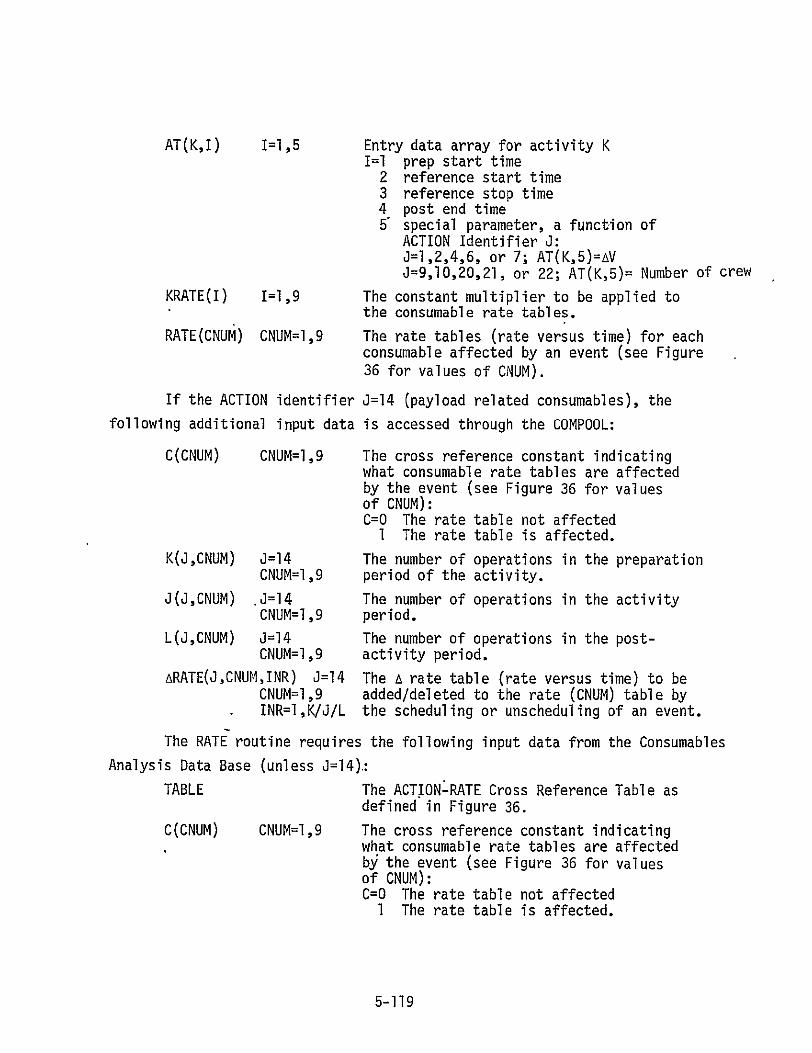
AT(K,I) I=1,5
KRATE(I) 1=1,9
RATE(CNUM) CNUM=l,9
Entry data array for activity K I=1 prep start time 2 reference start time 3 reference stop time 4 post end time 5 special parameter, a function of
ACTION Identifier J: J=1,2,4,6, or 7; AT(K,5)=AV J=9,10,20,21, or 22; AT(K,5)= Number of crew
The constant multiplier to be applied to the consumable rate tables.
The rate tables (rate versus time) for each consumable affected by an event (see Figure 36 for values of CNUM).
If the ACTION identifier J=14 (payload related consumables), the
following additional input data is accessed through the COMPOOL:
C(CNUM) CNUM=I,9
K(J,CNUM) J=14 CNUM=I,9
J(J,CNUM) J=14 CNUM=l,9
L(J,CNUM) J=14 CNUM=I,9
ARATE(J,CNUM,INR) J=14 CNUM=1,9 INR=I,K/J/L
The cross reference constant indicatingwhat consumable rate tables are affected by the event (see Figure 36 for values of CNUM): C=O The rate table not affected I The rate table is affected.
The number of operations in the preparation period of the activity.
The number of operations in the activity period.
The number of operations in the postactivity period.
The A rate table (rate versus time) to be added/deleted to the rate (CNUM) table by the scheduling or unscheduling of an event.
The RATE routine requires the following input data from the Consumables
Analysis Data Base (unless J=14):
TABLE
C(CNUM) CNUM=I,9
The ACTIONLRATE Cross Reference Table as defined in Figure 36.
The cross reference constant indicating what consumable rate tables are affected bj the event (see Figure 36 for values of CNUM): C=O The rate table not affected 1 The rate table is affected.
5-119

K(J,CNUM) J=1,23 The number of operations in the preparation CNUM=I,9 period of the activity.
J(J,CNUM) J=1,23 The number of operations in the activity CNUM=I,9 period.
L(J,CNUM) J=1,23 The number of operations in the postCNUM=I,9 activity period.
ARATE(J,CNUM,INR) J=1,23 The A rate table (rate versus time) to be *CNUM=l,9 added/deleted to the'rate (CNUM) table by INR=l,K/3/L the scheduling or unscheduling of an event.
Processing - The flow diagram of the RATE routine is presented in
Figure 37.
Output - The RATE routine transmits the following data through the
COMPOOL:
TMIN The time to start constraint checking.
TMAX The time to end constraint checking.
CNUM The consumable rate table identifier
(see Figure 36 for values of CNUM).
RATE(CNUM) CNUM=I,9 The rate tables (rate versus time) for each consumable affected by an event.
5-120
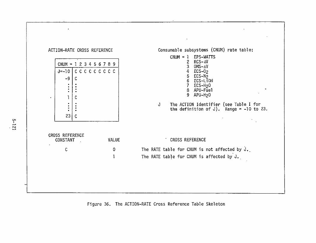
ACTION-RATE CROSS REFERENCE Consumable subsystems (CNUM) rate table:
CNUM = 1 EPS-WATTS 2 RCS-AVCNUM =1 2 3 4 5 6 7 8 9 3 OMS-AV
a=-1O C C C C C C C C C 4 ECS-02 9 5 ECS-N 29C 6 ECS-LiOH
7 ECS-H 20 8 APU-Fuel 9 APU-H201 C
J The ACTION Identifier (see Table I for the definition of J). Range = -10 to 23.
23
CROSS REFERENCE
CONSTANT VALUE CROSS REFERENCE
C 0 The RATE table for CNUM is not affected by J.
I The RATE table for CNUM is affected by J.
Figure 36. The ACTION-RATE Cross Reference Table Skeleton

ROUTINE RATE PAGE 1 OF 6
ENTER
EXTRACT ACTION IDENTIFIER J
~EXTRACT COPOOL
YES J=4CNUM=l,9
C(CNUM)
ENTERED THRU KEYBOARD
COMPOOL
CNSUM-ALES AALYSIS DTA
ASE
READ ENTRY FOR ACTION J FROM ACTION--RATE CROSS
VREFERENCE TABLE
C(CNUM) CNUM=I,9
CNUM=J
Figure 37. Flow Diagram for the RATE Routine
5-122

ROUTINE RATE PAGE 2 OF 6
1/2
C(CNUMH=IM= RETURN
4 YES NJO
COMPOOL
EXTRACTCNUM+1KRATE (I )
I=CNUM
CNUM =
COMPOOL
EXTRACT ACTION MODE, ACTIVITY #K,. AT(K,I) I=1 ,5
3/2
TFLAG=2
TIN=AT(K,2)TOUT=AT(K,3)•TKlTMIN=AT(K, 1)
TMAX=AT(K,4)
TFLAG= TIN=AT(K,1TOUT=AT(K,2)) TMIN=AT(K,I )
TMAX=AT(K,4)
1/3
Figure 37. Continued
5-123

ROUTINE RATE PAGE 3 OF 6
1/3
EXTRACT # OF CONSUM- OPERATIONS AS COMPOOL ABLES A FUNCTION OF (IF J=14). ANALYSIS TFLAG DATA BASE
OP =][ OP =OP
(J,CNUM) (I,CNUM) L (J, CNUM)
'YES
43 S INR=I
Figure 37. Continued
5-124

ROUTINE RATE PAGE 4 OF 6
EXTRACT ATIME/ CONSUM- ARATE FROM ABLES ARATE(J,CNUM,INR)O O ANALYSIS AS A FUNCTION DATA OF OPERATION BASE
ARATE = ARATE X KRATE(CNUM)
YES A A -ARATEDELET ARATEA
BTWENIN
~AND TOUT FORBETWEEN TIN
RATE AT COMPOOL TIME(INR)
Figure 37. Continued
5-125

ROUTINE RATE PAGE 5 OF 6
RATE AT TIME(INR)= RATE+ ARATE
PASS NEW RATE/TIME TO RATE TABLE FOR RATE(CNUM) COMPOOL
NO N
<j >•
INR== INR+l
Figure 37. Continued
5-126

ROUTINE RATE PAGE 6 OF 6
1 12 3
3/2 ATK,) NO
TFLAG=3
TIN=AT(K,3) TOUT=AT (K, 4)
PASS CNUM,TMAIN, TM4AXCOPL
~CALL
CONSTRAINT TO CHECK FOR RATE VIOLATIONS. IN RATE(CNUM)
Figure 37. Concluded
5-127

5.25 SEQUENCE ROUTINE
Description - The SEQUENCE routine establishes the time relationship between scheduled events by setting the temporal parameters in the File 1
data set. If an added/modified/deleted event affects the order of subsequent
events, the order will be adjusted and the temporal parameters of all subse
quent events will reflect the adjustment.
Interface
I/0 DEVICES - None. DATA BASE - COMPOOL for both input and output. ROUTINES CALLING SEQUENCE - ADD and DELETE routines. ROUTINES CALLED BY SEQUENCE - None.
Internal Variables
ISAVE The index for the position in the temporal parameters affected by the scheduled or unscheduled event.
Input - The SEQUENCE routine requires the following input data
accessed through the COMPOOL:
NOI The number of entries in sequence array.
IT(I) I=I,NOI Sequence array of activities.
TIM(I,L) I=I,NOI Start and end times of activities: L=1,2 L=l minimum start time of activity IT(I)
2 maximum end time of activity IT(I).
ACTION MODE Mode flag for the ACTION routine to schedule or unschedule an event: ADD = schedule an event DELETE = unschedule an event
K The activity number for the event to be scheduled or unscheduled.
AT(K,I) I=1,5 Entry data array for actiVity K I= prep start time 2 reference start time 3 reference stop time 4 post end time 5 special parameter, a function of ACTION
Identifier J: J=1,2,4,6, or 7. AT(K.5-)=AVJ=9,10,20,21, or 22; AT(K,5)=Number of crew.
5-128

Processing - The flow diagram of the SEQUENCE routine ispresented
in Figure 38.
Output - The SEQUENCE routine transmits the following data through
the COMPOOL:
NOI The number of entries in sequence array.
IT(I) I=1,NOI Sequence array of activities.
TIM(I,L) I=I,NOI L=1,2
Start and end times of activities: L=1 minimun start time of activity IT(I) 2 maximum end time of activity IT(I).
5-129

ROUTINE SEQUENCE PAGE 1 OF 4
ENTER
EXTRACT COI-IPOOL FILE 1
TEMPORAL PARAMETERS
NOI, IT(1) I=1,NOI TIM(I,L)
I=I,NQI L=1 ,2
EXTRACT ACTION MODE
LOHPOOL ''#_AND ACTIVITY
EXTRACT ENTRY DATA
COMPOOL ARRAY
AT(K,I) I=1,5
Figure 38. Flow Diagram for the SEQUENCE Routine
5-130

2/2
ROUTINE SEQUENCE PAGE 2 OF 4
ISAVE=I I=11NOI+I S ISAVE=
IT(I+] )=IT(I)TIM,(I+I,I1)=TI14(I,I)
TIM(I+1,2)=TIM(I,2)
1=+1I=I+I 1/3
I=NOI
NO
1-1+]
YES
Figure 38. Continued
5-131

ROUTINE SEQUENCE PAGE 3 OF 4
NOI= NOI+I
I=ISAVE
IT(I)=K TIM(I,I)=AT(K,I) TIM(I,2)=AT(K,4)
PASS UPDATED FILE 1 TEMPORAL COMPOOL PARAMETERS
rliQ, IT(I) I=1,I1 TIM(I,L)
I=I ,NoI L=1 ,2
RETURN
Figure 38. Continued
5-132

ROUTINE
SEQUENCE PAGE 4 OF 4
1/4
11=0
3/4
IT(I)=K
jYES
TIM(I,1)=TIM(I+1,i) TIM(I,2)=TIIM(I+,2)
N
1= 1101
NO
2/4
YES
.NOI=NOI-1 IT(NOI +])=BLANK TIM(NOI+,1)=BLANK TIM(NOI+,2)=BLANK
Figure 38. Concluded
5,-133

5.26 SPECIAL ROUTINE
Description - The SPECIAL routine provides special handling required
to schedule or unschedule specific events as a function of the ACTION
Identifier J. The special handling includes: setting the special parameter
AT(K,5) in the File 1 data entry array; setting constant multipliers to
be used in applying consumable rates to the rate tables; calling computa
tional routines that utilize spacecraft subsystem modeling; processing
specific payload consumable rates input by the user; and preparing the
data required to impose common block (J<O) rates on the consumable rate
tables.
Interface
I/0 DEVICES - The terminal KEYBOARD unit for input.DATA BASE - COMPOOL for both input and output. ROUTINES CALLING SPECIAL - ACTION, BUILD, and FLIGHT routines. ROUTINES CALLED BY SPECIAL - CFLT, COMS, CRCS, CATH, CREND, COOCK
CUDOCK, CEVA, CIVA, CES, and CWM computational routines.
Internal Variables - None.
Input - The SPECIAL routine requires the following input data accessed
through the COMPOOL:
J The ACTION identifier required by the event to be scheduled or unscheduled (see Table I for the values of J).
K Activity number for the event to be scheduled or unscheduled.
NCREW The number of crew required to perform an event.
If the ACTION identifier J<0, the following additional data are
required accessed through the COMPOOL:
BPT(I) I=1,11 Block phase times I=1 prelaunch start 2 prelaunch stop/ascent start 3 liftoff 4 MECO 5 ETS 6 OMS ignition/on-orbit start 7 on-orbit stop/deorbit start 8, deorbit burn ignition 9 deorbit stop/entry start
10 rollout 11 entry/land stop. 5-134

If the ACTION identifier J=14 (payload related'consumables), the
following input data is accessed through the terminal KEYBOARD unit:
REF START The reference start time for the eveht to be scheduled or unscheduled.
REF STOP The reference stop time for the event to be scheduled or unscheduled.
KRATE(I) I=1,9 The constant multiplier to be applied to the consumable rate tables.
C(CNUM) CNUM=I,9 The cross reference constant indicating what consumable rate tables are affected by the event (see Figure 36 for values of CNUM): C=O The rate table not affected 1 The rate table is affected.
K(J,CUNM) J=14 The number of operations in the preparation CNUM=I,9 period of the activity.
J(J,CNUM) J=14 The number of operations in the activity CNUM=I,9 period.
L(J,CNUM) J=14 The number of operations in the postCNUM=l,9 activity period.
ARATE(J,CNUM,INR) J=14 The A rate table (rate versus time) to be CNUM=l,9 added/deleted to the rate (CNUM) table by INR=1,K/J/L the scheduling or unscheduling of an event.
Processing - The flow diagram of the SPECIAL routine is presented
in Figure 39.
Output - The SPECIAL routine transmits the following data through
the COMPOOL:
AT(K,5) The special parameter in the entry data array for activity K as a function of ACTION Identifier J: J=1,2,4,6, or 7; AT(K,5)=AV J=9,10,20,21, or 22; AT(K,5)=Number of crew.
KRATE(I) I=1,9 The constant multiplier to be applied to the consumable rate tables.
If the ACTION identifier J=14, the following additional output
data will be transmitted through the COMPOOL:
5-135

C(CNUM) CNUM=l,9 The cross reference constant indicating what consumable rate tables are affected by the event (see Figure 36 for values of CNUM): C=O The rate table not affected 1 The rate table is affected.
K(J,CNUM) J=14 The number of operations in the preparation CNUM=l,9 period of the activity.
J(J,CNUM) J=14 The number of operations in the activity CNUM=I,9 period.
L(J,CNUM) J=14 The number of operations in the postCNUM-l,9 activity period.
ARATE(J,CNUM,INR) J=14 The A rate table (rate versus time) to be CNUM=I,9 added/deleted to the rate (CNUM) table by INR=l,K/J/L the scheduling or unscheduling of an event.
REF START The reference start time for the event to be scheduled or unscheduled.
REF STOP The reference stop time for the event to be scheduled or unscheduled.
If the ACTION identifier J<O, the following additional output data
will be transmitted through the COMPOOL:
REF START The reference start time for the common block to be scheduled or unscheduled.
REF STOP The reference stop time for the common block to be scheduled or unscheduled.
j The ACTION identifier for the common block to be scheduled or unscheduled (see Table I for the values of J).
5-136

ROUTINE SPECIAL PAGE 1 OF 5
ENTER
SET KRATE(I) I=1,9 EQUAL TO I
KRATE (I ) C014POOL I=1I,9
EXTRACTCOMPOOL ACCTION
IDENTIFIER J
YES
Figure 39. Flow Diagram for the SPECIAL Routine
5-.137

ROUTINE SPECIAL,PAGE 2 OF 5
J=1,2,3,4,6,7,9,10,20,21,22
SYES -'
CALL
COMPUTATIONAL ROUTINES
AS A FUNCTION OF J
1 CFLT 9 CEVA
2 COMS 10 CIVA
3 CRCS 20 CES
4 CREND 21 CES
-6-CDOCK 22 CWM
7 CUDOCK
Figure 39. Continued
5-138

ROUTINE SPECIAL PAGE 3 OF 5
KEY- ACCEPT THE
BFOLLOWING KEYBOARD ENTRIES
REF START, REF STOP, KRATE(I) 1=1,9 C(CNUM) CNUM=1,9 K(14,CNUM) CNUM=1 ,9 J(14,CNUM) CNUM=1,9 ,L(14,CNUM) CNUM=1,9 ARATE(J,CNUM,INR)
CHUM=, ,9 INR=I ,K/J/L
PASS ABOVE DATA TO COMPOOL COMPOOL
Figure 39. Continued
5-139

ROUTINE SPECIAL
PAGE 4 OF 5
1/4
YES SET J=l
PASS THE I 1 ACTION
,JJ+- NOO IDENT IEI ER COMPOOL
I=-d
EXTRACT BPT(1) I=1 ,11 FROM FILE ICOMPOO
/ DATA
REF START BPT(I) REF STOP= BPT(I+I)
PASS ACTION
IDENTIFIER J, REF START, COMPOOL
AND REF STOP
Figure 39. Continued
5-140

ROUTINE
SPECIAL PAGE 5 OF 5
115
CALL CFLT COMPUTATIONAL ROUTINE FOR KRATE(I)
2/2
Figure 39. Concluded
5-141

5.27 TIMELINE ROUTINE
Description - The TIMELINE routine prepares the scheduled events
versus time data for display. The mechanization of this process will be
defined at time of implementation.
Interface
I/0 DEVICES - None. DATA BASE - COMPOOL for both input and output. ROUTINES CALLING TIMELINE - OUTPUT and CONSUM HISTORY routines. ROUTINES CALLED BY TIMELINE - None.
Internal Variables - None.
Input - Will be defined during implementation.
Processing - The TIMELINE routine is an information management type
of routine used to prepare the results of consumables analysis for display.
No flow diagram is necessary.
Output - Will be defined during implementation.
5-142

6.0 DEFINITION OF THE COMPUTATIONAL ROUTINES
The computational routines defined in this section perform specific manipulation of the input and/or consumables data base information required prior to processing several of the activities. For propulsion-related
activities, these routines calculate the equivalent acceleration, burn time, and activity start of stop time., For crew-,related activities, these routines evaluate the impact of the number of crew members involved in the activity on the consumables usage rates.
6-1
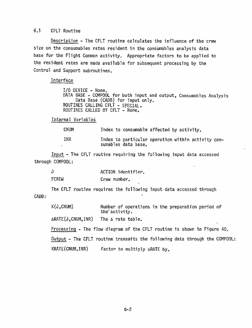
6.1 CFLT Routine
Description - The CFLT routine calculates the influence of the crew size on the consumables rates resident in the consumables analysis data
base for the Flight Common activity. Appropriate factors to be applied to the resident rates are made available for subsequent processing by the
Control and Support subroutines.
Interface
I/0 DEVICE - None. DATA BASE - COMPOOL for both input and output, Consumables Analysis
Data Base (CADB) for input only.ROUTINES CALLING CFLT - SPECIAL. ROUTINES CALLED BY CFLT - None.
Internal Variables
CNUM Index to consumable affected by activity.
INR Index to particular operation within activity consumables data base.
Input - The CFLT routine requiring the following input data accessed
through COMPOOL:
J ACTION identifier.
FCREW Crew number.
The CFLT routine requires the following input data accessed through
CADB:
K(J,CNUM) Number of operations in the preparation period of the-activity.
ARATE(J,CNUM,INR) The A rate table.
Processing - The flow diagram of the CFLT routine is shown in Figure 40.
Output - The CFLT routine transmits the following data through the COMPOOL:
KRATE(CNUM,INR) Factor to multiply ARATE by.
6-2

ENTER ROUTINE CFLT PAGE 1 OF 3
COMPOOL EXTRACT ACTION IDENTIFIER J, FCREW.
CONSUMABLES ANALYSIS EXTRCT DATA BASE K(J,CNUM)
INR=K(J,CNUM)+]
CONSUMABLES EXTRACT ANALYSISS- TE(J,CMUM,INR
DATABASEA=RATE(J,CNUM,INR
KRATE(CNUM,INR)= I+ .073*FCREW
PASS KRATE(CNUM,INR) COMPOOL
Figure 40. Flow Diagram for the CFLT Routine
6-3

1/2 ROUTINE CFLT
PAGE 2 OF 3
CNUM=6
12/2
CONSUMABLES EXTRACT ANALYSIS DATA BASE
K(J,CNUM)
INR=K(J,CNUM)+
KRATE(CNUM,INR)=FCREW
PASS KRATE(CNUM,INR) COMPOOL
1/3
Figure 40. Continued
6-4

ROUTINE CFLT PAGE 3 OF 31/3
CM=7 W__1NM=
- YES
Figure 40. Concluded
6-5

6.2 COMS Routine
Description - The COMS routine calculates the burn time, activity
reference stop time, and the acceleration rate for an OMS maneuver.
Interface
I/0 DEVICE - None. DATA BASE - COMPOOL for both input and output, Consumables Analysis
Data Base (CADB) for input only. ROUTINES CALLING COMS - SPECIAL. ROUTINES CALLED BY COMS - None.
Internal Variables
CNUM Index to consumable affected by activity.
INR Index to particular operation with activity consumables data base.
DEL OMS burn time.
Input - The COMS routine requiring the following input data accessed
through COMPOOL:
O ACTION identifier.
K Activity number.
AT(K,I)I=I,5 Entry data array for activity.
The COMS routine requires the following input data accessed through
CADB:
K(J,CNUM) Number of operations in the preparation period of the activity.
Processing - The flow diagram of the COMS routine is shown in Figure 41.
Output - The COMS routine transmits the following data through the COMPOOL:
KRATE(CNUM,INR) Factor to multiply ARATE by.
AT(K,I)I=l,5 Entry data array for activity.
6-6

ROUTINE COMS PAGE 1 OF 2
ENTER
J AND|--- )IDENTIFIERCOMPOOL tACT IV
ITY # K
EXTRACT
COMPOOL AT(K,) I ,5
CNUM=3 "
EXTRACTCONSUMABLES
K(J,CAUM)ANALYSIS
DATA BASE
DTLK,=COS-TK,5)
hT(K,3)=AT(K,2)+oELINR=K(J ,CNUM)+ . KRATE(CNUM,INR)=AT(K5)/DEL
/f2
Flow Diagram for the COIMS Routine Figure 41.
6-7

ROUTINE COMS PAGE 2 OF 2
COMPOOL I 1)I =,5IAT(K,I)1/2I=,
RA (CNUM,INR)
RETURN
Figure 41. Concluded
6-8

6.3 CRCS Routine
Description - The CRCS routine calculates the burn time, activity
reference stop time, and the acceleration rate for an RCS translation
maneuver.
Interface
I/O DEVICE - None. DATA BASE - COMPOOL for both input and output, Consumables Analysis
Data Base (CADB) for input only. ROUTINES CALLING CRCS - SPECIAL. ROUTINES CALLED BY CRCS - None.
Internal Variables
CNUM Index to consumable affected by activity.
INR Index to particular operation with activity consumables data base.
DEL RCS burn time,
Input - The CRCS routine requiring the following input data accessed
through COMPOOL:
J ACTION identifier.
K Activity number.
AT(K,I)I=I,5 Entry data array for activity.
The CRCS routine requires the following input data accessed through
CADB:
K(J,CNUM) Number of operations inthe preparation period Of the activity.
Processing - The flow diagram of the CRCS routine is shown in Figure 42.
Output - The CRCS routine transmits the following data through the COMPOOL:
KRATE(CNUM,INR) Factor to multiply ARATE by.
AT(K,I)I=1,5 Entry data array for activity.
6-9

ROUTINE CRCS PAGE 1 OF 2
ilEXTRACT ACTION COMPOOL IDENTIFIER J AND
ACTIVITY #C
COMPOOLEXTRACTCOMPOOL AT(K,I) I=1,5
I CONSUMABLES EXTRACTI ANALYSIS K(J,CNUM) I DATA BASE
DEL=CONST.AT(K,5) AT(K,3)=AT(K,2)+DEL INR=K(J,CNUM)+1 KRATE(CNUM,INR)=AT(K,5)/DEL
Figure 42. Flow Diagram for the CRCS Routine
6-10

ROUTINE CRCS PAGE 2 OF 2
1/2
PASS AT(K,I) I=1,5 COMPOOL KRATE(CNUM,INR)
RETURN
Figure 42. Concluded
6-11

6.4 CATH Routine
Description - The CATH routine calculates the RCS propellant required
for an attitude hold at various altitudes.
Interface
I/0 DEVICE - None. DATA BASE - COMPOOL for both input and output, Consumables Analysis
Data Base (CADB) for input only. ROUTINES CALLING CATH - SPECIAL. ROUTINES CALLED BY CATH - None.
Internal Variables
CNUM Index to consumable affected by activity.
INR Index to particular operation with activity consumables data base.
Input - The CATH routine requiring the following input data accessed
through COMPOOL:
J ACTION identifier.
K Activity number.
AT(K,I)I=I,5 Entry data array for activity.
The CATH routine requires the following input data accessed through
CADB:
K(J,CNUM) Number of operations in the preparation period of the activity.
F(AT(K,5)) Equivalent acceleration rate for attitude hold.
Processing - The flow diagram of the CATH routine is shown in Figure 43.
Output - The CATH routine transmits the following data through the COMPOOL:
KRATE(CNUM,INR) Factor to multiply ARATE by.
6-12

ROUTINE CATH PAGE I1OF 2
EXTRACT ACTION 2OM L ACT IVITY #K
COMPOOI EXTRACT
COMPOOL AT(K,I) I=1,5
I I
CONSUMABLES EXTRACT ANALYSIS K(J,CNUM) DATA BASE I
CONSUMABLES READ F(a) FROM ATTITUDE ANALYSIS t HOLD CURVE AS FUNCTION DATA BASE OF AT(K,5)
KRATE(CNUM,INR)=F(a)
Figure 43. Flow Diagram for the CATH Routine
6-13

ROUTINE CATH PAGE 2 OF 2
KRATE(CNUMINR) COMPOOL
IRETURN
'Figure 43. Concluded
6-14

6.5 CREND Routine
Description - The CREND routine calculates the burn time, activity
reference stop time, and the acceleration rate for a rendezvous braking
burn.
Interface
I/0 DEVICE - None.' DATA BASE - COMPOOL for both input and output, Consumables Analysis
Data Base (CADB) for input only.ROUTINES CALLING CREND - SPECIAL. ROUTINES CALLED BY CREND - None.
0 Internal Variables
CNUM Index to consumable affected by activity.
INR Index to particular operation with activity consumables data base.
DEL RCS burn time.
Input:- The CREND routine requiring the following input data accessed
through COMPOOL:
J ACTION identifier,
K Activity number.
AT(K,I)I=I,5 Entry data array for activity.
The CREND routine requires the following input data accessed through
CADB:
K(J,CNUM) Number of operations in the preparation period of the activity.
Processing - The flow diagram of the CREND routine is shown in Figure 44.
Output - The CREND routine transmits the following data through the COMPOOL:
KRATE(CNUM,INR) Factor to multiply ARATE by.
AT(K,I)I=1,5 Entry data array for activity.
6-15

ROUTINE CREND PAGE 1 OF 2
I!EXTRACT ACTION COMPOOL IDENTIFIER J AND
ACTIVITY #K
EXTRACT
COMPOOL AT(K,I) I=1,5
ii S CNUM=2
CONSUMABLES REXTRCT ANALYSIS K(JCNUM) DATA BASE
DEL=CONST-AT(K,5) AT(K,3)=AT(K,2)+DEL INR=K(J,CNUM)+1 KRATE(CNUM,INR)=AT(K,5)/DEL
Figure 44. Flow Diagram for the CREND Routine
6-16

ROUTINE CREND PAGE 2 OF 2
1/2
PASS AT(K,I) 1=1,5 COMPOOL KRATE(CNUM,INR)
4RETURN
Figure 44. Concluded
6-17

6.6 CDOCK Routine
Description - The CDOCK routine calculates the burn time, activity reference start time, and the acceleration rate for a docking maneuver.
Interface
I/0 DEVICE - None. DATA BASE - COMPOOL for both input and output, Consumables Analysis
Data Base (CADB) for input only.ROUTINES CALLING CDOCK - SPECIAL. ROUTINES CALLED BY CDOCK - None.
Internal Variables
CNUM Index to consumable affected by activity.
INR Index to particular operation with activity consumables data base.
DEL RCS burn time.
Input - The CDOCK routine requiring the following input data accessed through COMPOOL:
O ACTION identifier.
K Activity number.
AT(K,I)I=I,5 Entry data array for activity.
The CDOCK routine requires the following input data accessed through
CADB:
K(J,CNUM) Number of operations in the preparation period of the activity.
Processing - The flow diagram of the CDOCK toutine is shown in Figure 45.
Output - The CDOCK routine transmits the following data through the COMPOOL:
KRATE(CNUM,INR) Factor to multiply ARATE by.
AT(K,I)I=I,5 Entry data array for activity.
6-18
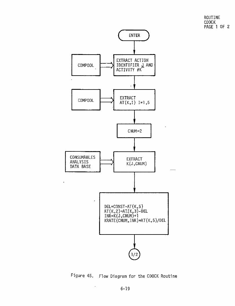
ROUTINE CDOCK PAGE 1 OF 2
(ENTER)
EXTRACT ACTION COMPOOL IDENTIFIER J AND
ACTIVITY #K
EXTRACTC O AT(K,I) I=1,5
CNUM=2
I CONSUMABLES EXTRACT ANALYSIS K(J,CNUM)DATA BASE
DEL=CONST.AT(K,5) AT(K,2)=AI(K,3)-DEL INR=K(J,CNUM)+IKRATE(CNUM,INR)=AT(K,5)/DEL
Figure 45. Flow Diagram for the CDOCK Routine
6-19

ROUTINE CDOCK PAGE 2 OF 2
1
COMPOOLPASS
I=1,5AT(K,I)
KRATE(CNUMINR)
RETURN
Figure 45. Concluded
,6-20

6.7 CUDOCK
Description - The CUDOCK routine calculates the burn time, activity reference stop time, and the acceleration rate for an undocking maneuver.
Interface
I/0 DEVICE - None. DATA BASE - COMPOOL for both input and output, Consumables Analysis
Data Base (CADB) for input only. ROUTINES CALLING CUDOCK - SPECIAL. ROUTINES CALLED BY CUDOCK - None.
Internal Variables
CNUM Index to consumable affected by activity.
INR Index to particular operation with activity consumables data base.
DEL RCS burn time.
Input - The CUDOCK routine requiring the following input data accessed
through COMPOOL:
J ACTION identifier.
K Activity number.
AT(K,I)I=I,5 Entry data array for activity.
The CUDOCK routine requires the following input data accessed through
CADB:
K(J,CNUM) Number of operations in the preparation period of the activity.
Processing - The flow diagram of the CUDOCK routine is shown in Figure 46.
Output - The CUDOCK routine transmits the following data through the COMPOOL:
KRATE(CNUM,INR) Factor to multiply ARATE by.
AT(K,I)I=I,5 Entry data array for activity.
6-21

ROUTINE CUDOCK PAGE I OF 2
ENTER
EXTRACT ACTION SIDENTIFIER I ANDACTIVITY #C
COMPOCOPOL EXTRACTATtK,I) 1=1,5
H, ~i I CONSUKABLES ANALYSIS DATA BASE
EXTRACT K(J,CNUM)
DEL=CONST.AT(K,5) AT(K,3)=AT(R,2)+DEL INR=K(J,CNUM)+I KRATE(CNUM,PR)=AT(K,5)/DEL
Figure 46. Flow Diagram for the CUDOCK Routine
6-22

ROUTINE CUDOCK PAGE 2 OF 2'
1/2
PASS AT(K,I) I=1,5 COMPOOL KRATE(CNUM,INR)
CRETURN
Figure 46. Concluded
6-23

6.8 CEVA Routine
Description - The CEVA routine calculates the influence of the EVA team
size on the consumables rates resident in the consumables analysis data base
for the EVA activity. Appropriate factors to be applied to the resident rates
are made available for subsequent processing by the Control and Support
subroutines.
Interface
I/0 DEVICE - None. DATA BASE - COMPOOL for both input and output, Consumables Analysis
Data Base (CADB) for input only, ROUTINES CALLING CEVA - SPECIAL. ROUTINES CALLED BY CEVA - None.
Internal Variables
CNUM Index to consumable affected by activity.
INR Index to particular operation within activity consumables data base.
II(I) Internal indexing of K(J,CNUM).
11(2) Internal indexing of J(J,CNUM)o
11(3) Internal indexing of L(J,CNUM).
JJ Operations counter0
I Operations counter index.
KK Flag to skip particular operation.
Input - The CEVA routine requiring the following input data accessed
through COMPOOL:
J ACTION identifier.
K Activity number.
AT(K,I)I=I;5 Entry data array for activity.
The CEVA routine requires the following input data accessed through
CADB:
K(J,CNUM) Number of operations in the preparation period of the activity.
6-24

J(J,CNUM) Number of operations in the activity period.
L(J,CNUM) Number of operations in the post-activity period.
Processing - The flow diagram of the CEVA routine is shown in Figure 47.
Output - The CEVA routine transmits the following data through the COMPOOL:
KRATE(CNUM,INR) Factor to multiply ARATE by.
6-25

ROUTINECEVAENTER PAGE 1 OF 3
EXTRACT ACTION
IDENTIFIER J AND COMPOOL #c<ACTIVITY
COMPOOL AT(K,I) 1=1,5
EXTRACT
'- EXTRACT
CONSUMABLES K(J,CNUM)
ANALYSIS DATA BASE
j(j,CNUM)L(J,CNUM)
II(])=K(J,CNUM) 1I(2)=J(J,CNUM) II(3)=L(J,CNUM) JJ=11(0) KK=II(2)+II(1)+I I=I INR=1
' RATE (C MUM, INR)
Flow Diagram for the CEVA Routine
Figure 47.
6-26

ROUTINE 1/2 CEVA.
PAGE 2 OF 3
PASS CMO KRATE(CNUM,INR)
IINRN+ 2/2 N=K /
NO YES
I=I+l
YES
1/3 Figure 47. Continued
6-27

ROUTINE 1/3 CEVA
PAGE 3 OF 3
CNUM=7
CONSUMABLESEXTRACT ANALYSIS K(JCN
KGJCNUM)DATA BASE
INR=K(J,CNUM)+1
KRATE(CNUM,INR) =FCREW
PASS KRATE(CNUM,INR) COMPOOL
CRETURN
Figure 47. Concluded
6-28

6.9 CIVA Routine
Description - The CIVA routine calculates the influence of the IVA team size on the consumables rates resident in the consumables analysis data base
for the IVA activity. Appropriate factors to be applied to the resident rates are made available for subsequent processing by the Control and Support
subroutines.
Interface
I/0 DEVICE - None. DATA BASE - COMPOOL for both input and output, Consumables Analysis
Data Base (CADB) for input only.ROUTINES CALLING CIVA - SPECIAL. ROUTINES CALLED-BY CIVA - None.
Internal Variables
CNUM Index to consumable affected by activity.
INR Index to particular operation within activity consumables data base.
Input - The CIVA routine requiring the following input data accessed
through COMPOOL:
i ACTION identifier.
K Activity number.
AT(K,I)I=I,5 Entry data array for activity.
The CIVA routine requires the following input data accessed through
CADB:
K(J,CNUM) Number of operations in the preparation period of the activity.
Processing - The flow diagram of the CIVA routine is shown in Figure 48.
Output - The CIVA routine transmits the following data through the COMPOOL:
KRATE(CNUM,INR) Factor to multiply ARATE by.
6-29

ROUTINE CIVA PAGE 1 OF 2
EXTRACT ACTION COMPOOL IDENTIFIER J AND
ACTIVITY #K
~EXTRACT
COMPOOL AT(K,I) I=1,5
CNUM=7
CONSUBLES l EXTRACT ANALYSISDATA BASE
K(J,CNUM)
INR=KGJ ,CNUM)-1
Figure 48. Flow Diagram for the CIVA Routine.
6-30

ROUTINE CIVA PAGE 2 OF 21/2
KRATE(CNUM,INR) =AT(K,5)
PASS
KRATE(CNUM,INR)
H O
COMPOOL
RETURN
Figure 48. Concluded
6-31
6.10 CES Routine
Description - The CES routine calculates the influence of the number of crew members sleeping or eating on the consumables rates resident in the consumables analysis data base for the eat or sleep activity. Appropriate factors to be applied to the resident rates are made available for subsequent processing by the Control and Support subroutines.
Interface
I/0 DEVICE - None. DATA BASE - COMPOOL for both input and output, Consumables Analysis
Data Base (CADB) for input only. ROUTINES CALLING CES - SPECIAL. ROUTINES CALLED BY CES - None.
Internal Variables
CNUM Index to consumable affected by activity.
INR Index to particular operation within activity consumables data base.
Input - The CES routine requiring the following input data accessed through COMPOOL:
J ACTION identifier.
K Activity number.
AT(K,I)I=l,5 Entry data array for activity.
The CES routine requires the following input data accessed through
CADB: 0
K(J,CNUM) Number of operations in the preparation period of the activity.
Processing - The flow diagram of the CES routine is shown in Figure 49.
Output - The CES routine transmits the following data through the COMPOOL:
KRATE(CNUM,INR) Factor to multiply ARATE by.
6-32

ROUTINE CES PAGE 1 OF 2
EXTRACT ACTION COMPOOL IDENTIFIER J AND
ACTIVITY #C
COMPOOLEXTRACT AT(K,I) 1=1,5
,1
'20 21
CNUM=6 CNUM=4
CONSUMABLES EXTRACT E(TCTANALYSIS KGJCNUM)DATA BASE
1/2
Figure 49. Flow Diagram for the CES Routine
6-33

ROUTINE C ES /2PAGE2 OF 2
INR=K(J,CNUM)+I
KRATE(CNUMINR) =AT(K,5)
PASS KRATE(CNUM,INR) COMPOOL
RETURN
Figure 49. Concluded
6-34

6.11 CWM Routine
Description - The CWM routine calculates the influence of the crew
size on the consumables rates resident in the consumables analysis data base for the Waste Management activity. Appropriate factors to be applied
to the resident rates are made available for subsequent processing by the
Control and Support subroutines.
Since the Waste Management activity has not been defined at this
time, this routine is TBD.
6-35