forschung für die praxis d 761 refresh ... · forschungsvereinigung stahlanwendung e.v. forschung...
TRANSCRIPT
Forschungsvereinigung Stahlanwendung e. V.
Forschung für die Praxis D 761
REFRESH - Lebensdauerverlängerung bestehender und neuer geschweißter Stahlkonstruktionen REFRESH - Extension of the fatigue life of existing and new welded steel structures
!
Translation of the original


Dokumentation D 761
REFRESH – Lebensdauerverlängerung bestehender und neuer geschweißter Stahlkonstruktionen REFRESH – Extension of the fatigue life of existing and new welded steel structures
Verantwortlich für die FOSTA – Forschungsvereinigung Stahlanwendung e. V.
Dipl.-Ing. Gregor Nüsse MSc
Dieses Forschungs- und Entwicklungsprojekt Nr. 02PB2103 wurde mit Mitteln des Bundesministeriums für Bildung und Forschung (BMBF) im Rahmenkonzept „Forschung für die Produktion von morgen“ gefördert und vom Projektträger Karlsruhe (PTKA) betreut. Die Verantwortung für den Inhalt dieser Veröffentlichung liegt beim Autor. Des Weiteren erhielt dieses Projekt den EUREKA-Status.
© 2010 Verlag und Vertriebsgesellschaft mbH, Düsseldorf
Printed in Germany
Bestell-Nr. D 761 ISBN 3-937567-88-7
Ansprechpartner bei der Forschungsvereinigung Stahlanwendung e.V.:
Dipl.-Ing. G. Nüsse MSc Tel.: +49 (0)211 / 6707-856; Fax: +49 (0)211 / 6707-840
Das Werk ist urheberrechtlich geschützt. Alle Rechte, auch die der Übersetzung in andere Sprachen, bleiben vorbehalten. Ohne schriftliche Genehmigung des Verlages sind Vervielfältigungen, Mikroverfilmungen und die Einspeicherung und Verarbeitung in elektronischen Systemen nicht gestattet.
Autoren:
Versuchsanstalt für Stahl, Holz und SteineKIT Karlsruher Institut für Technologie (ehem. Universität Karlsruhe), Karlsruhe Univ.-Prof. Dr.-Ing. Thomas Ummenhofer Dr.-Ing. Stefan Herion Dipl.-Ing. Stefan Rack
Ingenieursozietät Peil, Ummenhofer und Partner, Karlsruhe Dr.-Ing. Imke Weich
DYNATEC Gesellschaft für CAE und Dynamik mbH, Braunschweig Dr.-Ing. Gerd Telljohann Dr.-Ing. Sven Dannemeyer
Kranbau Köthen GmbH, Köthen Dipl.-Ing. Holger Strohbach
LKT Klebtechnik GmbH, Aachen Dipl.-Ing. Hamdollah Eslami-Chalandar
MAN B&W Diesel Gruppe, Augsburg Dr.-Ing. Anne Kathrin Kern Dipl.-Ing. Dietmar Pinkernell
Maurer Söhne GmbH & Co. KG, München Dr.-Ing. Michael Smida
REpower System AG, Hamburg Dipl.-Ing. Uwe Rahlf
Schachtbau Nordhausen GmbH, Nordhausen Dipl.-Ing. Burkhard Senk

KurzdarstellungIn den letzten Jahren hat die Bedeutung der Lebensdauer von Bauwerken neben der Optimierung des Konstruktionsgewichts zur Reduzierung der Herstellungskosten an Bedeutung gewonnen. Entscheidend für die Lebensdauer zyklisch beanspruchter geschweißter Stahlkonstruktionen sind hoch beanspruchte Schweißnahtdetails. Durch eine Anhebung der Ermüdungsfestigkeit dieser Kerbdetails kann die Lebensdauer der Gesamtkonstruktion verlängert werden. Dies kann durch eine Nachbehandlung der Schweißnähte mit verschiedenen Methoden geschehen.
Während im Bauwesen bislang einzig das Beschleifen der Schweißnähte eingesetzt wird, werden in anderen Branchen bereits Verfahren wie das Kugelstrahlen oder das Verfestigen erfolgreich angewendet. Eine Vielzahl von Veröffentlichungen zeigt die positive Wirkung von gezielt genutzten Schweißnahtnachbehandlungsmethoden. Neuere Untersuchungen bestätigen dabei die besondere Wirkung höherfrequenter Hämmerverfahren.
Voraussetzung für eine breite Einführung von lebensdauerverlängernden Maßnahmen, insbesondere im Bauwesen ist, dass neben der reinen Anwendung der Verfahren zur Lebensdauerverlängerung bestehender und neuer Stahlkonstruktionen, Verfahren zur Berechnung und Quantifizierung der erzielbaren Effekte sowie entsprechende Qualitätssicherungssysteme bereitgestellt werden müssen. Einsatzmöglichkeiten, Auswirkungen sowie Grenzen der Verfahren müssen auf der Basis umfassender statistisch abgesicherter Untersuchungen als Stand der Technik anerkannt sein und Bestandteil entsprechender Richtlinien werden.
Im Rahmen dieses Forschungsvorhabens wurden umfangreiche Untersuchungen zur Wirkungsweise und Wirksamkeit der höherfrequenten Hämmerverfahren durchgeführt.
Die Ergebnisse der experimentellen Untersuchungen zeigen, dass die positive Wirkung der höherfrequenten Hämmerverfahren, HiFIT und UIT, auf den durch die plastische Verformung des Nahtübergangs erzeugten Druckeigenspannungen und Randschichtverfestigungen beruht. Die Rissinitiierungsphase wird verlängert und die Rissfortschrittsphase durch Rissschließeffekte verzögert, so dass die experimentell ermittelte Ermüdungsfestigkeit um 80 bis 100 Prozent gegenüber einer unbehandelten Schweißnaht erhöht wird. Dieselbe Verbesserung wird bei vorgeschädigten makrorissfreien Schweißnähten erzielt.
Die Geräte wurden in Hinblick auf ihre maximale Wirksamkeit, ihre Prozesssicherheit und ihre Anwendbarkeit in der Praxis optimiert. Die zum Erreichen einer Prozesssicherheit erforderlichen Geräteeinstellungen wurden analysiert und definiert und ein Qualitätssicherungskonzept entwickelt. Dieses Konzept verlangt die
Erstellung und Zertifizierung von Verfahrensanweisungen, die Durchführung von Anwenderschulungen und Prüfungen sowie die Durchführung von Qualitätskontrollen. Durch die Weiterentwicklung eines mikromagnetischen Messsystems wird ein Messsystem für die Prüfung der Anwendung der zertifizierten höherfrequenten Hämmerverfahren für von der Standardanwendung abweichende Bauteile bereitgestellt.
Verschiedene Bemessungskonzepte wurden basierend auf lokalen Konzepten zur genauen Berechnung der Lebensdauer entwickelt, anhand der experimentellen Ergebnisse verifiziert und abschließend analysiert. Als Resultat wurde ein vereinfachtes Bemessungskonzept entwickelt, dass dem Ingenieur eine konservative Bemessung von Bauteilen ermöglicht.
Als Ergebnis des Vorhabens steht ein ganzheitliches Konzept, das sowohl Qualitätsanforderungen sicherstellt als auch Bemessungsvorschriften bereitstellt. Aufbauend auf den untersuchten Verfahren HiFIT und UIT wurde damit gemeinschaftlich von der BAM Bundesanstalt für Materialforschung und -prüfung und der VA Versuchsanstalt für Stahl, Holz und Steine der Universität Karlsruhe ein Zertifizierungsverfahren entwickelt. Dieses Zertifizierungsverfahren steht jetzt neben HiFIT und UIT auch für weitere Verfahren zur Verfügung. Derzeit wird in nationalen und internationalen Gremien an der Umsetzung der Ergebnisse in Richtlinien gearbeitet. Damit wird zukünftig nicht nur die Anwendung dieser Verfahren, sondern auch die Berücksichtigung bei der Bemessung im Rahmen der definierten Grenzen möglich sein.
FOSTA – Forschungsvereinigung Stahlanwendung e. V.
Februar 2010
Abstract
In the last years optimization of life time of constructions besides optimization of material consumption in order to reduce the production costs gained more importance. For cyclic loaded welded steel structures the fatigue strength of highly stressed welded details is decisive for the fatigue life. By enhancing the fatigue strength of these details the fatigue life of the whole structure can be increased.
While in civil engineering only overall grinding is applied so far in other industries methods like shot peening and strain hardening are successfully utilized. The benefit of systematically applied improvement methods is reported in numerous research studies. Recent investigations prove that especially high frequency peening methods are effective means to improve the fatigue strength.
Precondition for a widespread application of fatigue life enhancing methods especially in civil engineering is that besides the pure application of the methods design concepts and quality control systems are provided. Fields of application, consequences and limits of the application have to be accepted as state of the art based on statistically verified investigations and have to be included in the design codes.
In the range of this research project comprehensive investigations regarding the mode of functioning and the effectiveness of high frequency peening methods have been accomplished. The results of the experimental studies show that the benefit of high frequency peening methods relies on compressive residual stresses and surface hardening caused by plastic deformation of the edge layers at the weld toes. Crack initiation phase is increased and crack propagation velocity in the field of compressive residual stresses up to 1.5 mm depth is reduced due to crack closure so that the experimentally determined fatigue strength is improved up 80 to 100 percent compared to the as welded condition. The same improvement can be gained for fatigue affected welds, which do not exhibit macro cracks.
The devises have been optimized in view of their maximum efficiency, process reliability and practicability. The devise parameters which are required for process reliability have been analysed and a quality control concept has been developed. This concept requests the preparation and certification of application procedures, the accomplishment of user training and assessment as well as quality controls. With the further development of a micro magnetic measurement system a measurement device for applications variant from the standard applications is provided.
Various design concepts based on local approaches for an accurate fatigue life assessment have been developed, verified by the experimental results and finally
analysed. As a result a simplified design concept has been developed which allows the engineer a conservative design of assemblies and structures.
As result of the project an integrated concept is available which ensures quality requirements and provides design guides. Based on this concept a certification procedure has been developed by the BAM- Federal Institute for Materials Research and Testing- and the VA, Versuchsanstalt für Stahl, Holz und Steine of the Karlsruher Institute of Technology, it has been successfully completed for the investigated methods HiFIT and UIT and is offered for new devices. Currently, national and international bodies work on the implementation of te results in design guidelines. In future these will allow the consideration of the beneficial effects in the design beyond the pure application of the methods.
FOSTA - Research Association for Steel Application
February 2010
Contents
Seite I
Contents
1 Introduction............................................................................................................1
2 Initial situation and aims of the application and implementation .................2 2.1 Post-weld treatment ....................................................................................... 2 2.2 Aims of the application and implementation................................................ 3
3 High frequency peening methods ......................................................................4 3.1 High Frequency Impact Treatment (HiFIT).................................................... 4 3.2 Ultrasonic Impact Treatment (UIT) ................................................................ 5
4 Effectiveness und mode of operation................................................................6 4.1 Surface layer modifications........................................................................... 6
4.1.1 Strain hardening................................................................................... 6 4.1.2 Residual compressive stresses ............................................................ 7 4.1.3 Reduction of residual stress ............................................................... 10 4.1.4 Changes in seam geometry................................................................ 11 4.1.5 Optimal treatment parameters ............................................................ 12
4.2 Increase of fatigue strength......................................................................... 12 4.2.1 Material............................................................................................... 14 4.2.2 Notch detail ........................................................................................ 15 4.2.3 Influence of scale................................................................................ 15 4.2.4 Influence of sheet thickness ............................................................... 16 4.2.5 Mean stress........................................................................................ 17 4.2.6 Seam geometry .................................................................................. 18 4.2.7 Quasi-static pre-stressing................................................................... 19 4.2.8 Additional abrasive blasting................................................................ 19 4.2.9 Extension of remaining fatigue life...................................................... 20
5 Quality assurance ...............................................................................................21 5.1 Micro magnetic measurement method....................................................... 21 5.2 Visual examination....................................................................................... 23 5.3 Process examination.................................................................................... 23
5.3.1 Treatment parameters ........................................................................ 24 5.3.2 Weld preparation................................................................................ 25
5.4 Safety aspect ................................................................................................ 25 5.5 Acknowledgement of further high frequency hammer peening
(HFH) methods.............................................................................................. 25 5.5.1 General............................................................................................... 25 5.5.2 Conditions for acknowledgement........................................................ 26 5.5.3 Experimental verification..................................................................... 26 5.5.4 Investigations on alterations in seam geometry .................................. 26
Contents
Seite II
5.5.4.1 Investigations on distribution of residual stresses................ 26 5.5.4.2 Fatigue tests for analysing the fatigue strength of
post-treated welds ............................................................... 27 5.6 Measures for quality assurance.................................................................. 27
5.6.1 Manufacturer qualification and user training....................................... 27
6 Design concept....................................................................................................28 6.1 General.......................................................................................................... 28
6.1.1 Proceedings........................................................................................ 28 6.1.2 Inclination of the Wöhler curve............................................................ 28 6.1.3 Factor KHP........................................................................................... 28
6.1.3.1 Improvement factor k0.......................................................... 29 6.1.3.2 Material factor kRe ................................................................ 29 6.1.3.3 Strain factor kR..................................................................... 29
6.1.4 Excessive load.................................................................................... 29 6.1.5 Extension of fatigue life....................................................................... 30
7 Examples of application.....................................................................................31 7.1 Maurer Söhne ............................................................................................... 31 7.2 MAN............................................................................................................... 33 7.3 REpower........................................................................................................ 33 7.4 Schachtbau Nordhausen............................................................................. 35 7.5 Kranbau Köthen ........................................................................................... 35
8 Summary...............................................................................................................37
List of figures
Seite III
List of figures Figure 2-1: Post-weld treatment methods and their mode of operation [17]
Figure 3-1: HiFIT device: prototype and version for industrial use
Figure 3-2: UIT device with water cooling and generator
Figure 4-1: UCI surface hardness HV0.3 S355J2 depending on the type of treatment, AW: as-welded; HiFIT
Figure 4-2: UCI surface hardness HV0.3 S690QL depending on the type of treatment, AW: as-welded; HiFIT
Figure 4-3: Transverse and longitudinal residual stresses at the weld toe in untreated and HiFIT and UIT untreated states. (S355J2)
Figure 4-4: Transverse and longitudinal residual stresses at the weld toe in untreated and HiFIT and UIT treated states (S690QL)
Figure 4-5: Schematic display of possible surface residual stress conditions at the weld toe following a HiFIT or UIT treatment.
Figure 4-6: Schematic diagram of the depth distribution after a HiFIT or UIT treatment, left: transverse residual stresses, right: longitudinal residual stresses
Figure 4-7: Notch factor depending on fillet radius and depth of groove
Figure 4-8: Notch details investigated (t = 16 mm) butt weld and longitudinal stiffener for materials S355J2 and S690QL
Figure 4-9: Comparison of the fatigue test results of HiFIT and UIT treated, MAG and submerged arc welded transverse butt joints as a function of the steel quality, R = 0.1
Figure 4-10: Comparison of the fatigue test results of HiFIT and UIT treated, MAG and submerged arc welded longitudinal stiffeners as a function of the steel quality, R = 0.1
Figure 4-11: Comparison of the fatigue test results of HiFIT and UIT treated, MAG welded transverse butt joints S690QL as a function of the sample width: b=60 mm and 120 mm, R = 0.1
Figure 4-12: Comparison of the fatigue test results of HiFIT and UIT treated, MAG welded longitudinal stiffeners S355J2 as a function of the sample width: b=60 mm and 120 mm, R = 0.1
Figure 4-13: Comparison of the fatigue strength of untreated as well as HiFIT and UIT treated transverse butt joints made of steel S355J2 and S690QL, depending on the sheet thickness.
Figure 4-14: Comparison of the fatigue strength for HiFIT and UIT treated longitudinal stiffeners made of steel S355J2 and S690QL as a function of the sheet thickness
Figure 4-15: Comparison of the fatigue strength for HiFIT and UIT treated, MAG welded transverse butt joints made of steel S355J2 as a function of the stress ratio
List of tables
Seite IV
Figure 4-16: Comparison of Wöhler test results for HiFIT/UIT treated and HiFIT/UIT treated and subsequently stress relief annealed (SAG) transverse butt joints (S690QL)
Figure 4-17: Comparison of Wöhler test results for HiFIT/UIT treated transverse butt joints (S355), which are subsequently exposed to a quasi-static tensile or compressive strain and purely HiFIT/UIT treated transverse butt joints (S355)
Figure 4-18: Comparison of fatigue test results for HiFIT/UIT treated and subsequently abrasively blasted transverse butt joints (S690QL) and only HiFIT/UIT treated MAG welded transverse butt joints (S690QL)
Figure 4-19: Comparison of fatigue test results between transverse butt joints (S355J2 and S690QL), which were vibrated until they reached the numerically determined fatigue life and subsequently HiFIT/UIT treated and undamaged HiFIT/UIT treated samples
Figure 5-1: Micro magnetic measurement system Qualimax II with sensor
Figure 5-2: Residual transverse and longitudinal stresses from roentgenographically determined residual stresses and residual stresses determined with micro magnetic parameters in steel S690QL and HiFIT treated samples, using the determined regression equation.
Figure 5-3: Comparison of residual longitudinal stress curve and Mmax (left) and comparison of the full width at half maximum and Coercitivity (right)
Figure 5-4: Definition of application angle
Figure 5-5 HiFIT- (left) and UIT- (right) treated weld toe
Figure 7-1: HiFIT treatment of a swivel joist, Maurer Söhne
Figure 7-2: Schenkendorfstraße Bridge over the Mittlerer Ring (ring road), Munich
Figure 7-3: Post-weld treatment of fillet welds on the Schenkendorfstraße Bridge
Figure 7-4: REpower wind turbines with jacket near Bremerhaven
Figure 7-5: Transition construction being produced
Figure 7-6: HiFIT Post-weld treatment on the lower area of the transition piece.
Figure 7-7: Post-weld treatment on vibrating heads, Schachtbau Nordhausen
Figure 7-8: Teeming crane 90t x 26m
List of tables
Table 4-1: Parameter of Wöhler fatigue test series conducted

List of abbreviations
Seite V
List of abbreviations
a Crack depth
c Crack length
k0 Improvement factor
kRe Material factor depending on the yield strength Re
kR Strain factor depending on the stress ratio R
R Ratio minimum to maximum stress caused by load from the outside
∆σc,HP Fatigue strength of post-weld treated welds
∆σc Fatigue strength of untreated welds
Introduction
Seite 1
1 Introduction Inevitable maintenance and renewal of existing buildings and infrastructure regularly cause extraordinarily high, and still increasing, costs for the national economy of Germany. Moreover, using raw materials efficiently, that is designing structures in an optimal way, is becoming more and more important.
Steel structures form a substantial proportion of existing buildings and facilities. There are often altering or dynamic loads that lead to fatigue of material and thus restrict the structure’s fatigue life due to its endurance strength. Welded joints are particularly critical details because of the notch effect. So far it has not been possible to gain an advantage by using high strength steel, as in regulations the fatigue strength of welded details is stipulated independently of the material strength.
One possibility to lower the disadvantageous effect of fatigue damage, which substantially reduces the fatigue life of structures subject to altering stress and as a result strain the national economy, is methods of post-weld treatment. Occasionally, these methods have already been applied with good results in mechanical engineering. An improvement of the weld’s fatigue strength leads in most cases to an increase in the fatigue life of the whole construction.
The condition for a broad implementation of fatigue life increasing methods, particularly in the building industry, is that they become an integral part of a whole concept. This means that parallel to the sheer application of fatigue life increasing methods with existing and new steel structures, suitable quality assurance systems will have to be provided as well as methods to calculate and quantify its achievable effects. Such a holistic concept has to be able to depict the life cycle from the production through to the usage and maintenance. Fields of application, effects, as well as limits of the methods, have to be acknowledged as state of the art on the basis of safe comprehensive statistic investigations and they have to become part of respective standards. The ultimate goal of the REFRESH research project was the development of such a holistic concept in order to increase the remaining fatigue life of existing steel structures and to increase the fatigue life and fatigue strength of new steel structures.
The German Federal Ministry of Education and Research (BMBF) financed the research project. Due to the transnational economical importance a co-operation with other European partners was wanted and realised within the frame of a EUREKA-Umbrella-PRO-FACTORY-Project. In this extensive alliance of European project partners, coming from the industrial sector, federal agencies and research institutes, as well as from an accompanying industrial association conducted by the FOSTA, the application possibilities, its limits and the methods for quality assurance were investigated.
The essential results of the research project, on the basis of which it is possible to apply the methods, and which can be considered when designing parts, are presented in this compendium. More detailed information about the investigations and results are documented in the final report [9].
Initial situation and aims of the application and implementation
Seite 2
2 Initial situation and aims of the application and implementation
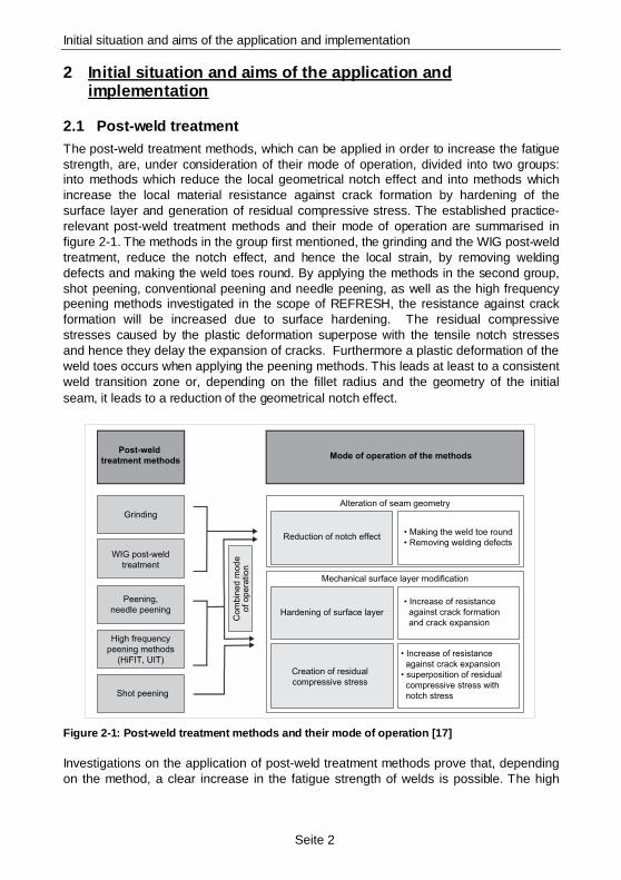
2.1 Post-weld treatment The post-weld treatment methods, which can be applied in order to increase the fatigue strength, are, under consideration of their mode of operation, divided into two groups: into methods which reduce the local geometrical notch effect and into methods which increase the local material resistance against crack formation by hardening of the surface layer and generation of residual compressive stress. The established practice-relevant post-weld treatment methods and their mode of operation are summarised in figure 2-1. The methods in the group first mentioned, the grinding and the WIG post-weld treatment, reduce the notch effect, and hence the local strain, by removing welding defects and making the weld toes round. By applying the methods in the second group, shot peening, conventional peening and needle peening, as well as the high frequency peening methods investigated in the scope of REFRESH, the resistance against crack formation will be increased due to surface hardening. The residual compressive stresses caused by the plastic deformation superpose with the tensile notch stresses and hence they delay the expansion of cracks. Furthermore a plastic deformation of the weld toes occurs when applying the peening methods. This leads at least to a consistent weld transition zone or, depending on the fillet radius and the geometry of the initial seam, it leads to a reduction of the geometrical notch effect.
Post-weld
treatment methods
Grinding
WIG post-weld
treatment
Peening,
needle peening
High frequency
peening methods
(HiFIT, UIT)
Shot peening
Com
bin
ed m
ode
of opera
tion
Mode of operation of the methods
Alteration of seam geometry
Reduction of notch effect• Making the weld toe round
• Removing welding defects
Mechanical surface layer modification
Hardening of surface layer
Creation of residual
compressive stress
• Increase of resistance
against crack formation
and crack expansion
• Increase of resistance
against crack expansion
• superposition of residual
compressive stress with
notch stress
Figure 2-1: Post-weld treatment methods and their mo de of operation [17]
Investigations on the application of post-weld treatment methods prove that, depending on the method, a clear increase in the fatigue strength of welds is possible. The high
Initial situation and aims of the application and implementation
Seite 3
frequency peening methods, which were shown in already existing surveys at the start of the project, have proven particularly effective [5], [7].
2.2 Aims of the application and implementation Due to the high frequency peening method’s high effectiveness and because of their easy handling in situ the focus of the investigations was put on these methods. Detailed analyses on the mode of operation and on the method’s sensitivity in connection with specific parameters of details and methods were not known at the start of the project. These were analysed in the scope of REFRESH and the results were used as a base for the development of a code of practice for a quality assurance and design concept. Another main focus was put on the application of the method on existing structures.
High frequency peening methods
Seite 4
3 High frequency peening methods High frequency impact treatment (HiFIT) and ultrasonic impact treatment (UIT) are classed as high frequency peening methods. Hence, there is a new group of post-weld treatment methods, which is defined by this generic term. This method distinguishes itself from conventional peening, or hammer peening, by its significantly higher peening frequency. In contrast to conventional methods, which work within a frequency range of 20 to 100 Hz, the post-weld treatment with high frequency peening methods is carried out with frequencies of over 180 Hz. Moreover, this method produces defined surface layer modifications, which cause a substantial increase in fatigue strength. One main focus of this research project was the thorough analysis of these surface layer modifications.
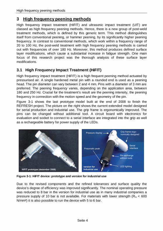
3.1 High Frequency Impact Treatment (HiFIT) High frequency impact treatment (HiFIT) is a high frequent peening method actuated by pressurised air. A single hardened metal pin with a rounded end is used as a peening head. The pin diameter can vary between 2 and 4 mm. Pins with a diameter of 3 mm are preferred. The peening frequency varies, depending on the application area, between 180 and 250 Hz. Crucial for the treatment’s result are the peening intensity, the peening frequency in connection with the motion speed and the geometry of the pin.
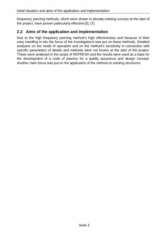
Figure 3-1 shows the last prototype model built at the end of 2008 to finish the REFRESH project. The picture on the right shows the current extended model designed for serial production and industrial use. The grip frame is ergonomically improved. The pins can be changed without additional tool. A circuit board with electronics for evaluation and socket to connect to a serial interface are integrated into the grip as well as a rechargeable battery for power supply of the LEDs.
LED lighting
Pressure display
Pneumatic peak
version for
industrial use
Pin exchange
without tools
Serial
interface
Grip frame ergo-
nomically designed
HiFIT prototype (dezember 2008) Figure 3-1: HiFIT device: prototype and version for industrial use
Due to the revised components and the refined tolerances and surface quality the device’s degree of efficiency was improved significantly. The nominal operating pressure was reduced to 8 bar in the version for industrial use as in many industrial companies a pressure supply of 10 bar is not available. For materials with lower strength (Rm < 600 N/mm²) it is also possible to run the device with 5 to 6 bar.
High frequency peening methods
Seite 5
Overview of the HiFIT device’s technical data:
• Pneumatic drive, pressure air supply with 6 to 8 bar, air requirement approx. 400 l/min
• Peening frequency and peening intensity adjustable to different materials.
• Peening frequency approx. 180 Hz to 250 Hz
• Motion speed approx. 5 mm/s
• Serial interface for calibration of the pin and for quality control; connection via a USB adapter, software is provided
• Recording of the peening process is possible
• Integrated LEDs to illuminate the work area
Further details about the development of the device are given in the final report [16] and [13].
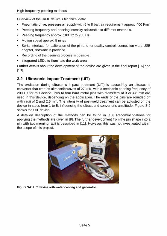
3.2 Ultrasonic Impact Treatment (UIT) The excitation during ultrasonic impact treatment (UIT) is caused by an ultrasound converter that creates ultrasonic waves of 27 kHz, with a mechanic peening frequency of 200 Hz for this device. Two to four hard metal pins with diameters of 3 or 4.8 mm are used in this device, depending on the application. The ends of the pins are rounded off with radii of 2 and 2.5 mm. The intensity of post-weld treatment can be adjusted on the device in steps from 1 to 5, influencing the ultrasound converter’s amplitude. Figure 3-2 shows the UIT device.
A detailed description of the methods can be found in [10]. Recommendations for applying the methods are given in [9]. The further development from the pin shape into a pin with two merging radii is described in [11]. However, this was not investigated within the scope of this project.
Figure 3-2: UIT device with water cooling and genera tor
Effectiveness und mode of operation
Seite 6
4 Effectiveness und mode of operation Comprehensive investigations were carried out to analyse the effectiveness and mode of operation of the high frequency peening methods. The treatment parameters’ influence on the surface layer modifications and the sensitivity of the methods on applications with varying or rather sub-optimal parameters and basic conditions was investigated. The results of the investigations are summarised as follows. More detailed descriptions of the analyses and investigations of the mode of operation and effectiveness can be found in [17] and [16].
4.1 Surface layer modifications
4.1.1 Strain hardening
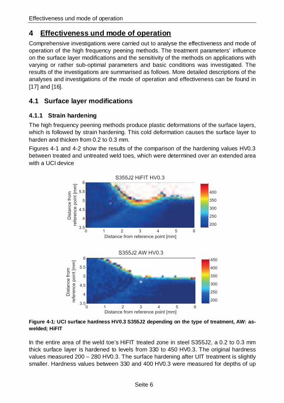
The high frequency peening methods produce plastic deformations of the surface layers, which is followed by strain hardening. This cold deformation causes the surface layer to harden and thicken from 0.2 to 0.3 mm.
Figures 4-1 and 4-2 show the results of the comparison of the hardening values HV0.3 between treated and untreated weld toes, which were determined over an extended area with a UCI device
0 1 2 3 4 5 63.5
4
4.5
5
5.5
6S355J2 HiFIT HV0.3
Distance from reference point [mm]
Dis
tan
ce
fro
m
refe
ren
ce
po
int
[mm
]
200
250
300
350
400
0 1 2 3 4 5 63.5
4
4.5
5
5.5
6
S355J2 AW HV0.3
Distance from reference point [mm]
Dis
tance fro
m
refe
rence p
oin
t [m
m]
200
250
300
350
400
450
Figure 4-1: UCI surface hardness HV0.3 S355J2 depend ing on the type of treatment, AW: as-welded; HiFIT
In the entire area of the weld toe’s HiFIT treated zone in steel S355J2, a 0.2 to 0.3 mm thick surface layer is hardened to levels from 330 to 450 HV0.3. The original hardness values measured 200 – 280 HV0.3. The surface hardening after UIT treatment is slightly smaller. Hardness values between 330 and 400 HV0.3 were measured for depths of up
Effectiveness und mode of operation
Seite 7
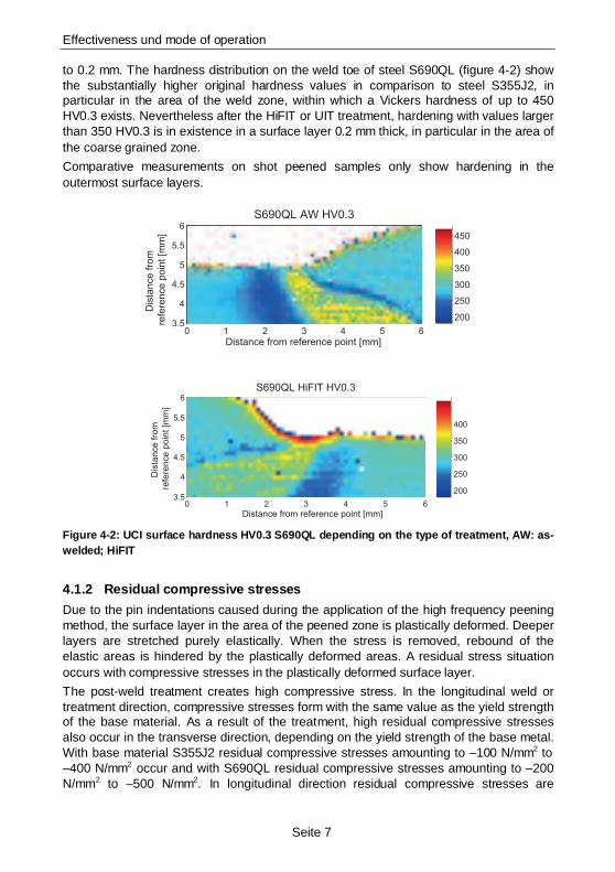
to 0.2 mm. The hardness distribution on the weld toe of steel S690QL (figure 4-2) show the substantially higher original hardness values in comparison to steel S355J2, in particular in the area of the weld zone, within which a Vickers hardness of up to 450 HV0.3 exists. Nevertheless after the HiFIT or UIT treatment, hardening with values larger than 350 HV0.3 is in existence in a surface layer 0.2 mm thick, in particular in the area of the coarse grained zone.
Comparative measurements on shot peened samples only show hardening in the outermost surface layers.
0 1 2 3 4 5 63.5
4
4.5
5
5.5
6
S690QL AW HV0.3
Distance from reference point [mm]
Dis
tance fro
m
refe
rence p
oin
t [m
m]
200
250
300
350
400
450
0 1 2 3 4 5 63.5
4
4.5
5
5.5
6
S690QL HiFIT HV0.3
Distance from reference point [mm]
Dis
tan
ce
fro
m
refe
ren
ce
po
int
[mm
]
200
250
300
350
400
Figure 4-2: UCI surface hardness HV0.3 S690QL depend ing on the type of treatment, AW: as-welded; HiFIT
4.1.2 Residual compressive stresses
Due to the pin indentations caused during the application of the high frequency peening method, the surface layer in the area of the peened zone is plastically deformed. Deeper layers are stretched purely elastically. When the stress is removed, rebound of the elastic areas is hindered by the plastically deformed areas. A residual stress situation occurs with compressive stresses in the plastically deformed surface layer.
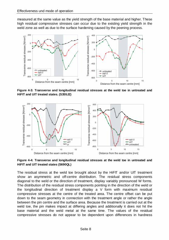
The post-weld treatment creates high compressive stress. In the longitudinal weld or treatment direction, compressive stresses form with the same value as the yield strength of the base material. As a result of the treatment, high residual compressive stresses also occur in the transverse direction, depending on the yield strength of the base metal. With base material S355J2 residual compressive stresses amounting to –100 N/mm2 to –400 N/mm2 occur and with S690QL residual compressive stresses amounting to –200 N/mm2 to –500 N/mm2. In longitudinal direction residual compressive stresses are
Effectiveness und mode of operation
Seite 8
measured at the same value as the yield strength of the base material and higher. These high residual compressive stresses can occur due to the existing yield strength in the weld zone as well as due to the surface hardening caused by the peening process.
-800
-600
-400
-200
0
200
0 5 10 15
Abstand von der Nahtmitte [mm]
unbehandeltHiFITUIT
-800
-600
-400
-200
0
200
400
0 5 10 15
Abstand von der Nahtmitte [mm]
unbehandeltHiFITUIT
-800
-600
-400
-200
0
200
0 5 10 15
Distance from the seam centre [mm]
Tra
nsvers
e r
esid
ual s
tresses [N
/mm
2]
untreatedHiFITUIT
-800
-600
-400
-200
0
200
400
0 5 10 15
untreatedHiFITUIT
Distance from the seam centre [mm]
Tra
nsvers
e r
esid
ual s
tresses [N
/mm
2]
Figure 4-3: Transverse and longitudinal residual str esses at the weld toe in untreated and HiFIT and UIT treated states. (S355J2)
-600
-400
-200
0
200
0 5 10 15
HiFITUITunbehandelt
-800
-600
-400
-200
0
200
400
600
0 5 10 15
HiFITUITunbehandelt
-600
-400
-200
0
200
0 5 10 15
HiFITUITuntreat
-800
-600
-400
-200
0
200
400
600
0 5 10 15
HiFITUITuntreated
Distance from the seam centre [mm]
Tra
nsvers
e r
esid
ual s
tresses [N
/mm
2]
Distance from the seam centre [mm]
Tra
nsvers
e r
esid
ual s
tresses [N
/mm
2]
Figure 4-4: Transverse and longitudinal residual str esses at the weld toe in untreated and HiFIT and UIT treated states (S690QL)
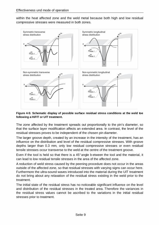
The residual stress at the weld toe brought about by the HiFIT and/or UIT treatment show an asymmetric and off-centre distribution. The residual stress components diagonal to the weld or the direction of treatment, display variably pronounced W forms. The distribution of the residual stress components pointing in the direction of the weld or the longitudinal direction of treatment display a V form with maximum residual compressive stresses at the centre of the treated area. The centre offset can be put down to the seam geometry in connection with the treatment angle or rather the angle between the pin centre and the surface area. Because the treatment is carried out at the weld toe, the pin makes impact at differing angles and additionally it does not hit the base material and the weld metal at the same time. The values of the residual compressive stresses do not appear to be dependent upon differences in hardness
Effectiveness und mode of operation
Seite 9
within the heat affected zone and the weld metal because both high and low residual compressive stresses were measured in both zones.
Symmetric transverse stress distribution
Symmetric longitudinal stress distribution
Non-symmetric transverse stress distribution
Non-symmetric longitudinal stress distribution
Figure 4-5: Schematic display of possible surface re sidual stress conditions at the weld toe following a HiFIT or UIT treatment.
The zone affected by the treatment spreads out proportionally to the pin’s diameter, so that the surface layer modification affects an extended area. In contrast, the level of the residual stresses proves to be independent of the chosen pin diameter.
The larger groove depth, created by an increase in the intensity of the treatment, has an influence on the distribution and level of the residual compressive stresses. With groove depths larger than 0.3 mm, only low residual compressive stresses or even residual tensile stresses occur transverse to the weld at the centre of the treatment groove.
Even if the tool is held so that there is a 45° angle b etween the tool and the material, it can lead to low residual tensile stresses in the area of the affected zone.
A reduction of weld stress caused by the peening procedure does not occur in the areas outside of the affected zone, so that residual stresses with varying signs can occur here. Furthermore the ultra-sound waves introduced into the material during the UIT treatment do not bring about any relaxation of the residual stress existing in the weld prior to the treatment.
The initial state of the residual stress has no noticeable significant influence on the level and distribution of the residual stresses in the treated area. Therefore the variances in the residual stress values cannot be ascribed to the variations in the initial residual stresses prior to treatment.
Effectiveness und mode of operation
Seite 10
Investigations into the influence of a repeated post-weld treatment after a reduction of residual stresses caused by plastic deformation show that a second treatment is as effective as a first-time post-weld treatment. The second treatment generates residual compressive stresses at the same level as the initial treatment. The increased half-width measured after the second treatment suggests that the dislocation density has further increased as a result of the repeated treatment. This explains the renewed appearance of residual compressive stresses. The surface layer is further plastically deformed by the pin indentations so that residual compressive stresses occur after the release caused by the elastic rebound in lower lying areas.
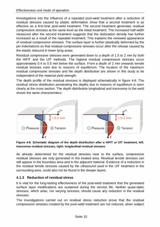
Residual compressive stresses were generated down to a depth of 1.5 to 2 mm by both the HiFIT and the UIT methods. The highest residual compressive stresses occur approximately 0.4 to 0.5 mm below the surface. From a depth of 2 mm onwards tensile residual stresses exist due to reasons of equilibrium. The location of the maximum residual compressive stresses and the depth distribution are shown in this study to be independent of the material yield strength.
The depth profile of the residual stresses is displayed schematically in figure 4-6. The residual stress distribution penetrating the depths due to reasons of equilibrium is seen clearly at the cross section. The depth distribution longitudinal and transverse to the weld shows the same characteristics.
1,5-2 mm 1,5-2 mm
+Druck Zug- +Druck Zug-
1,5-2 mm 1,5-2 mm
+Pressure Tension- - +Pressure Tension
Figure 4-6: Schematic diagram of the depth distribut ion after a HiFIT or UIT treatment, left: transverse residual stresses, right: longitudinal residual stresses
As already determined for the residual stresses near to the surface, compressive residual stresses are only generated in the treated area. Residual tensile stresses can still appear in the boundary area and in the adjacent material. Evidence of a reduction in the residual tensile stresses caused by the ultrasound used in the UIT treatment in the surrounding area, could also not be found in the deeper layers.
4.1.3 Reduction of residual stress
It is vital for the long-lasting effectiveness of the post-weld treatment that the generated surface layer modifications are sustained during the service life. Neither quasi-static stresses, which arise, nor varying stresses, should cause any reduction in the residual stresses.
The investigations carried out on residual stress reduction prove that the residual compressive stresses created by the post-weld treatment are not reduced, when subject

Effectiveness und mode of operation
Seite 11
to quasi-static compressive and tensile stress, up to the point of local notch strain above the yield strength of the base material, irrelevant of the yield strength of the base material.
Due to the changes in residual stress in the areas adjacent to the treated zone, merely small residual stress redistributions occur in the area of the treated zone.
No reduction of residual stress occurs in steel S355J2 (Re = 434 N/mm2) up to nominal stresses of +/- 300 N/mm2 at right angles to the weld. In steel S690QL (Re = 719 N/mm2) nominal stress of 550 (tensile) or –650 N/mm2 (compressive) still do not result in any transverse residual stress reduction. Investigations carried out by Weich [17] show that the elastic notch stress existing locally in S355 amounts to +/- 500 N/mm2 and that the limit equivalent stresses for S690QL amount to 1200 or –1050 N/mm2 without reduction of residual stress. This indicates a clearly increased yield strength, or offset yield stress, at the edge, compared to the base material, so that a reduction of residual stresses caused by plastification occurs only under high local strain with values which are far above the material’s nominal yield strength.
Under alternating strain it was verified for the nominal double stress amplitude of 400 N/mm2 that the residual compressive stresses in the treated area are sustained at the level of the original residual stresses, irrelevant of the material strength.
For the high strength material S690QL there is also no reduction of residual stress under fluctuating tension, with a stress range of 405 N/mm2. Thus, it was not possible to verify a reduction of residual stress up to a maximum stress of 62.5 % of the base material’s yield strength and therefore up to a strain which is close to the short-time strength. The effect of the initial residual compressive stresses, which increase the fatigue strength, can therefore be regarded as fully effective.
For low strength steel S355 a reduction of residual stress can be detected under fluctuating tension with a maximum stress of 80 % of the yield strength. The residual compressive stresses are altered by +/- 100 N/mm2 if they are exposed to between 10,000 and 100,000 load cycles. If the residual compressive stresses created by post-weld treatment are only of minor values, between –100 N/mm2 and –150 N/mm2, they can be completely depleted. Investigations with lower stress amplitudes do not exist. Because a reduction of residual stress only occurs if the local cyclic yield strength is exceeded, this will not be the case for low strain so that the residual compressive stresses are fully effective. In cases of low strain this can lead to a higher increase of fatigue strength than in cases of high strain.
4.1.4 Changes in seam geometry
The post-weld treatment leads either to a plane, or a rough but always to a consistent weld transition zone, depending on the method applied. The HiFIT method creates a plane and even track whereas individual indentations are clearly visible when applying the UIT method.
Using finite element calculation it was possible to analyse the influence of changes in seam geometry on the notch effect of butt and fillet welds. An increased weld radius generally leads to a reduction of the notch factor. An increased depth of groove however, increases the notch effect. In order to ensure the weld toe notch’s modification caused by post-weld treatment, it is necessary to have a minimum depth of groove, which may
Effectiveness und mode of operation
Seite 12
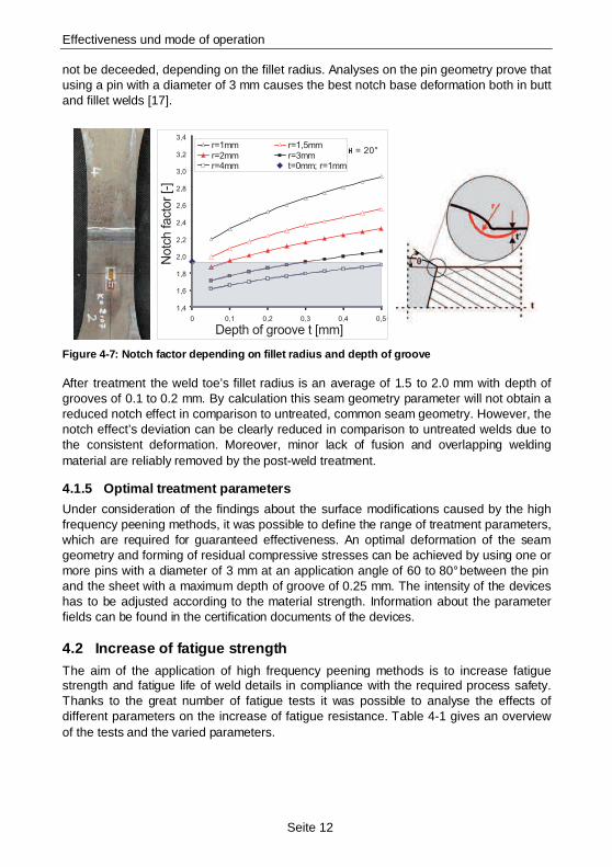
not be deceeded, depending on the fillet radius. Analyses on the pin geometry prove that using a pin with a diameter of 3 mm causes the best notch base deformation both in butt and fillet welds [17].
1,4
1,6
1,8
2,0
2,2
2,4
2,6
2,8
3,0
3,2
3,4
0 0,1 0,2 0,3 0,4 0,5
r=1mm r=1,5mm
r=2mm r=3mm
r=4mm t=0mm; r=1mm
= 20°
1,4
1,6
1,8
2,0
2,2
2,4
2,6
2,8
3,0
3,2
3,4
0 0,1 0,2 0,3 0,4 0,5
r=1mm r=1,5mmr=2mm r=3mmr=4mm t=0mm; r=1mm
= 20°
Notc
h facto
r [-
]
Depth of groove t [mm] Figure 4-7: Notch factor depending on fillet radius and depth of groove
After treatment the weld toe’s fillet radius is an average of 1.5 to 2.0 mm with depth of grooves of 0.1 to 0.2 mm. By calculation this seam geometry parameter will not obtain a reduced notch effect in comparison to untreated, common seam geometry. However, the notch effect’s deviation can be clearly reduced in comparison to untreated welds due to the consistent deformation. Moreover, minor lack of fusion and overlapping welding material are reliably removed by the post-weld treatment.
4.1.5 Optimal treatment parameters
Under consideration of the findings about the surface modifications caused by the high frequency peening methods, it was possible to define the range of treatment parameters, which are required for guaranteed effectiveness. An optimal deformation of the seam geometry and forming of residual compressive stresses can be achieved by using one or more pins with a diameter of 3 mm at an application angle of 60 to 80° between the pin and the sheet with a maximum depth of groove of 0.25 mm. The intensity of the devices has to be adjusted according to the material strength. Information about the parameter fields can be found in the certification documents of the devices.
4.2 Increase of fatigue strength The aim of the application of high frequency peening methods is to increase fatigue strength and fatigue life of weld details in compliance with the required process safety. Thanks to the great number of fatigue tests it was possible to analyse the effects of different parameters on the increase of fatigue resistance. Table 4-1 gives an overview of the tests and the varied parameters.
Effectiveness und mode of operation
Seite 13
Butt weld Longitudinal rib
Condition Untreated HiFIT treated UIT treated Shot peened Cyclically pre-stressed + HiFIT/UIT HiFIT/UIT + statically pre-stressed HiFIT/UIT + stress-relieved
Untreated Ground HiFIT treated UIT treated Shot peened Cyclically pre-stressed + HiFIT/UIT
Stress ratio R = 0.1 R = 0.5
R = 0.1
Materials S355J2 S690QL
S355J2 S690QL
Prestress Quasi-static tension Quasi-static compression Cyclical up to the calculated
- - Cyclical up to the calculated
Additional features fatigue life fatigue life Special investigations
Incipient crack Reduction of residual stress Crack progress
Incipient crack - -
Nominal cross section B x t
16 mm x 60 mm 16 mm x 120 mm 30 mm x 60 mm
16 mm x 60 mm 16 mm x 120 mm 30 mm x 60 mm
Table 4-1: Parameter of Wöhler fatigue test series conducted
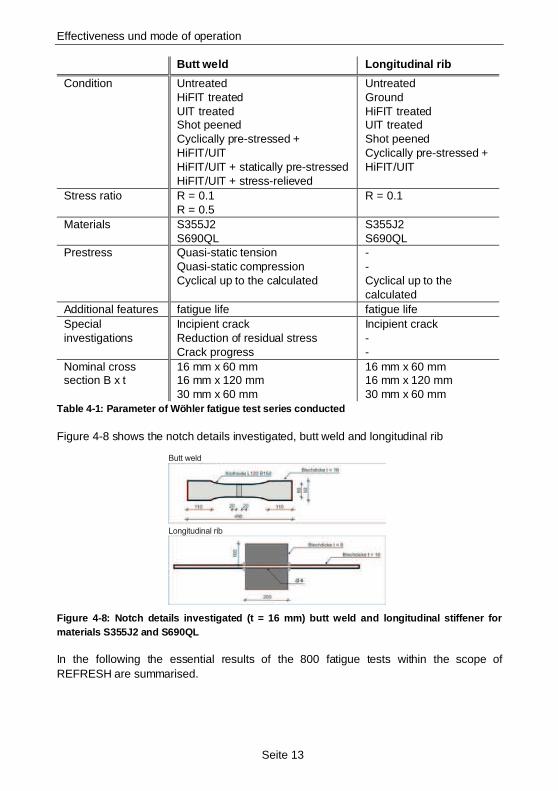
Figure 4-8 shows the notch details investigated, butt weld and longitudinal rib
Butt weld
Longitudinal rib
Figure 4-8: Notch details investigated (t = 16 mm) b utt weld and longitudinal stiffener for materials S355J2 and S690QL
In the following the essential results of the 800 fatigue tests within the scope of REFRESH are summarised.
Effectiveness und mode of operation
Seite 14
4.2.1 Material
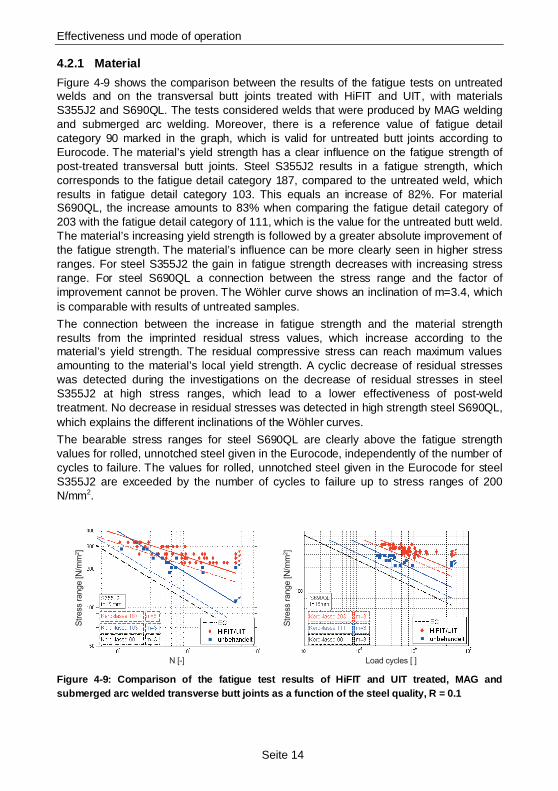
Figure 4-9 shows the comparison between the results of the fatigue tests on untreated welds and on the transversal butt joints treated with HiFIT and UIT, with materials S355J2 and S690QL. The tests considered welds that were produced by MAG welding and submerged arc welding. Moreover, there is a reference value of fatigue detail category 90 marked in the graph, which is valid for untreated butt joints according to Eurocode. The material’s yield strength has a clear influence on the fatigue strength of post-treated transversal butt joints. Steel S355J2 results in a fatigue strength, which corresponds to the fatigue detail category 187, compared to the untreated weld, which results in fatigue detail category 103. This equals an increase of 82%. For material S690QL, the increase amounts to 83% when comparing the fatigue detail category of 203 with the fatigue detail category of 111, which is the value for the untreated butt weld. The material’s increasing yield strength is followed by a greater absolute improvement of the fatigue strength. The material’s influence can be more clearly seen in higher stress ranges. For steel S355J2 the gain in fatigue strength decreases with increasing stress range. For steel S690QL a connection between the stress range and the factor of improvement cannot be proven. The Wöhler curve shows an inclination of m=3.4, which is comparable with results of untreated samples.
The connection between the increase in fatigue strength and the material strength results from the imprinted residual stress values, which increase according to the material’s yield strength. The residual compressive stress can reach maximum values amounting to the material’s local yield strength. A cyclic decrease of residual stresses was detected during the investigations on the decrease of residual stresses in steel S355J2 at high stress ranges, which lead to a lower effectiveness of post-weld treatment. No decrease in residual stresses was detected in high strength steel S690QL, which explains the different inclinations of the Wöhler curves.
The bearable stress ranges for steel S690QL are clearly above the fatigue strength values for rolled, unnotched steel given in the Eurocode, independently of the number of cycles to failure. The values for rolled, unnotched steel given in the Eurocode for steel S355J2 are exceeded by the number of cycles to failure up to stress ranges of 200 N/mm2.
Load cycles [ ]N [-]
Str
ess r
ange [N
/mm
2]
Str
ess r
ange [N
/mm
2]
Figure 4-9: Comparison of the fatigue test results o f HiFIT and UIT treated, MAG and submerged arc welded transverse butt joints as a function of the steel quality, R = 0.1
Effectiveness und mode of operation
Seite 15
4.2.2 Notch detail
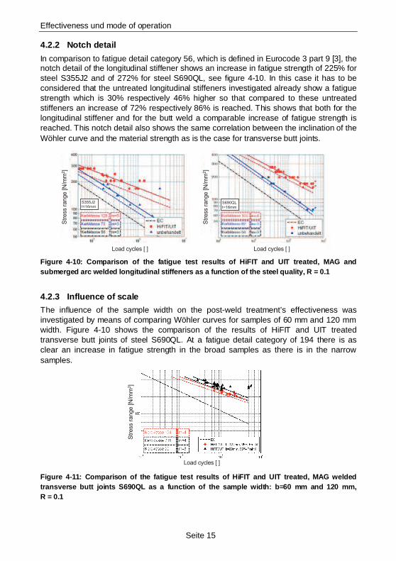
In comparison to fatigue detail category 56, which is defined in Eurocode 3 part 9 [3], the notch detail of the longitudinal stiffener shows an increase in fatigue strength of 225% for steel S355J2 and of 272% for steel S690QL, see figure 4-10. In this case it has to be considered that the untreated longitudinal stiffeners investigated already show a fatigue strength which is 30% respectively 46% higher so that compared to these untreated stiffeners an increase of 72% respectively 86% is reached. This shows that both for the longitudinal stiffener and for the butt weld a comparable increase of fatigue strength is reached. This notch detail also shows the same correlation between the inclination of the Wöhler curve and the material strength as is the case for transverse butt joints.
S355J2t=16mm
S690QLt=16mm
Load cycles [ ]Load cycles [ ]
Str
ess r
ange [N
/mm
2]
Str
ess r
ange [N
/mm
2]
Figure 4-10: Comparison of the fatigue test results of HiFIT and UIT treated, MAG and submerged arc welded longitudinal stiffeners as a function of the steel quality, R = 0.1
4.2.3 Influence of scale
The influence of the sample width on the post-weld treatment’s effectiveness was investigated by means of comparing Wöhler curves for samples of 60 mm and 120 mm width. Figure 4-10 shows the comparison of the results of HiFIT and UIT treated transverse butt joints of steel S690QL. At a fatigue detail category of 194 there is as clear an increase in fatigue strength in the broad samples as there is in the narrow samples.
Load cycles [ ]
Str
ess r
ange [N
/mm
2]
Figure 4-11: Comparison of the fatigue test results of HiFIT and UIT treated, MAG welded transverse butt joints S690QL as a function of the sample width: b=60 mm and 120 mm, R = 0.1
Effectiveness und mode of operation
Seite 16
All of the broad samples broke in the base material. A scale effect, which could lead to a slight reduction in fatigue strength, can therefore only be traced back to a higher probability of the occurrence of fractures in the base material in broader samples, and not to a lesser effectiveness of the post-weld treatment.
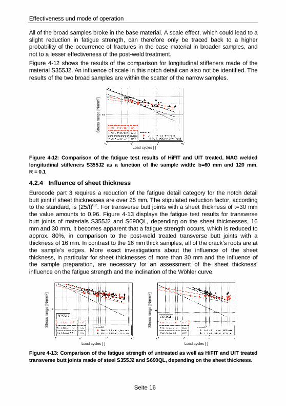
Figure 4-12 shows the results of the comparison for longitudinal stiffeners made of the material S355J2. An influence of scale in this notch detail can also not be identified. The results of the two broad samples are within the scatter of the narrow samples.
Load cycles [ ]
Str
ess r
ange [N
/mm
2]
Figure 4-12: Comparison of the fatigue test results of HiFIT and UIT treated, MAG welded longitudinal stiffeners S355J2 as a function of the sample width: b=60 mm and 120 mm, R = 0.1
4.2.4 Influence of sheet thickness
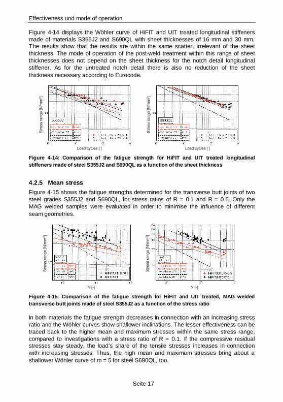
Eurocode part 3 requires a reduction of the fatigue detail category for the notch detail butt joint if sheet thicknesses are over 25 mm. The stipulated reduction factor, according to the standard, is (25/t)0.2. For transverse butt joints with a sheet thickness of t=30 mm the value amounts to 0.96. Figure 4-13 displays the fatigue test results for transverse butt joints of materials S355J2 and S690QL, depending on the sheet thicknesses, 16 mm and 30 mm. It becomes apparent that a fatigue strength occurs, which is reduced to approx. 80%, in comparison to the post-weld treated transverse butt joints with a thickness of 16 mm. In contrast to the 16 mm thick samples, all of the crack’s roots are at the sample’s edges. More exact investigations about the influence of the sheet thickness, in particular for sheet thicknesses of more than 30 mm and the influence of the sample preparation, are necessary for an assessment of the sheet thickness’ influence on the fatigue strength and the inclination of the Wöhler curve.
Load cycles [ ]Load cycles [ ]
Str
ess r
ange [N
/mm
2]
Str
ess r
ange [N
/mm
2]
Figure 4-13: Comparison of the fatigue strength of u ntreated as well as HiFIT and UIT treated transverse butt joints made of steel S355J2 and S690QL, depending on the sheet thickness.
Effectiveness und mode of operation
Seite 17
Figure 4-14 displays the Wöhler curve of HiFIT and UIT treated longitudinal stiffeners made of materials S355J2 and S690QL with sheet thicknesses of 16 mm and 30 mm. The results show that the results are within the same scatter, irrelevant of the sheet thickness. The mode of operation of the post-weld treatment within this range of sheet thicknesses does not depend on the sheet thickness for the notch detail longitudinal stiffener. As for the untreated notch detail there is also no reduction of the sheet thickness necessary according to Eurocode.
Load cycles [ ]Load cycles [ ]
Str
ess
range [N
/mm
2]
Str
ess
range [N
/mm
2]
Figure 4-14: Comparison of the fatigue strength for HiFIT and UIT treated longitudinal stiffeners made of steel S355J2 and S690QL as a function of the sheet thickness
4.2.5 Mean stress
Figure 4-15 shows the fatigue strengths determined for the transverse butt joints of two steel grades S355J2 and S690QL, for stress ratios of R = 0.1 and R = 0.5. Only the MAG welded samples were evaluated in order to minimise the influence of different seam geometries.
N [-]N [-]
Str
ess
range [N
/mm
2]
Str
ess
range [N
/mm
2]
Figure 4-15: Comparison of the fatigue strength for HiFIT and UIT treated, MAG welded transverse butt joints made of steel S355J2 as a function of the stress ratio
In both materials the fatigue strength decreases in connection with an increasing stress ratio and the Wöhler curves show shallower inclinations. The lesser effectiveness can be traced back to the higher mean and maximum stresses within the same stress range, compared to investigations with a stress ratio of R = 0.1. If the compressive residual stresses stay steady, the load’s share of the tensile stresses increases in connection with increasing stresses. Thus, the high mean and maximum stresses bring about a shallower Wöhler curve of m = 5 for steel S690QL, too.
Effectiveness und mode of operation
Seite 18
For material S355J2 and for stress ranges higher than 170 N/mm² the numbers of cycles to failure fall below the load cycle values determined according to Eurocode. In this case it has to be considered that the maximum stress in this stress range is already above the design value for static load. When analysing the effectiveness of post-weld treatment methods, the maximum stress value that belongs to the respective stress range always has to be considered, and whose admissible value is limited by the material’s yield strength.
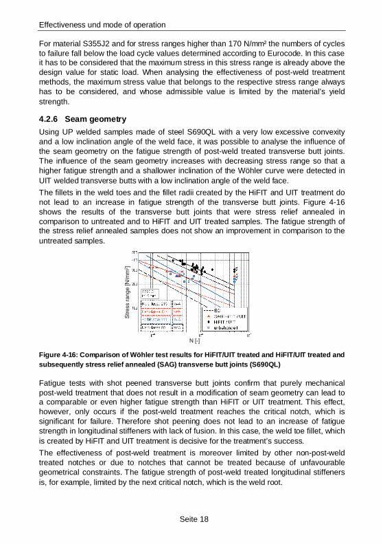
4.2.6 Seam geometry
Using UP welded samples made of steel S690QL with a very low excessive convexity and a low inclination angle of the weld face, it was possible to analyse the influence of the seam geometry on the fatigue strength of post-weld treated transverse butt joints. The influence of the seam geometry increases with decreasing stress range so that a higher fatigue strength and a shallower inclination of the Wöhler curve were detected in UIT welded transverse butts with a low inclination angle of the weld face.
The fillets in the weld toes and the fillet radii created by the HiFIT and UIT treatment do not lead to an increase in fatigue strength of the transverse butt joints. Figure 4-16 shows the results of the transverse butt joints that were stress relief annealed in comparison to untreated and to HiFIT and UIT treated samples. The fatigue strength of the stress relief annealed samples does not show an improvement in comparison to the untreated samples.
N [-]
Str
ess r
ange [N
/mm
2]
Figure 4-16: Comparison of Wöhler test results for H iFIT/UIT treated and HiFIT/UIT treated and subsequently stress relief annealed (SAG) transverse butt joints (S690QL)
Fatigue tests with shot peened transverse butt joints confirm that purely mechanical post-weld treatment that does not result in a modification of seam geometry can lead to a comparable or even higher fatigue strength than HiFIT or UIT treatment. This effect, however, only occurs if the post-weld treatment reaches the critical notch, which is significant for failure. Therefore shot peening does not lead to an increase of fatigue strength in longitudinal stiffeners with lack of fusion. In this case, the weld toe fillet, which is created by HiFIT and UIT treatment is decisive for the treatment’s success.
The effectiveness of post-weld treatment is moreover limited by other non-post-weld treated notches or due to notches that cannot be treated because of unfavourable geometrical constraints. The fatigue strength of post-weld treated longitudinal stiffeners is, for example, limited by the next critical notch, which is the weld root.
Effectiveness und mode of operation
Seite 19
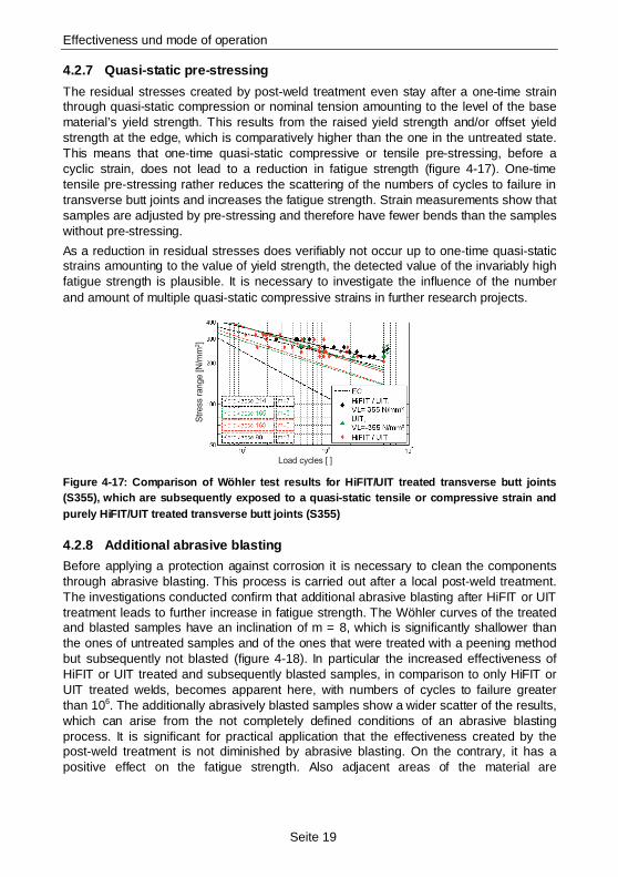
4.2.7 Quasi-static pre-stressing
The residual stresses created by post-weld treatment even stay after a one-time strain through quasi-static compression or nominal tension amounting to the level of the base material’s yield strength. This results from the raised yield strength and/or offset yield strength at the edge, which is comparatively higher than the one in the untreated state. This means that one-time quasi-static compressive or tensile pre-stressing, before a cyclic strain, does not lead to a reduction in fatigue strength (figure 4-17). One-time tensile pre-stressing rather reduces the scattering of the numbers of cycles to failure in transverse butt joints and increases the fatigue strength. Strain measurements show that samples are adjusted by pre-stressing and therefore have fewer bends than the samples without pre-stressing.
As a reduction in residual stresses does verifiably not occur up to one-time quasi-static strains amounting to the value of yield strength, the detected value of the invariably high fatigue strength is plausible. It is necessary to investigate the influence of the number and amount of multiple quasi-static compressive strains in further research projects.
Load cycles [ ]
Str
ess r
ange [N
/mm
2]
Figure 4-17: Comparison of Wöhler test results for H iFIT/UIT treated transverse butt joints (S355), which are subsequently exposed to a quasi-static tensile or compressive strain and purely HiFIT/UIT treated transverse butt joints (S355)
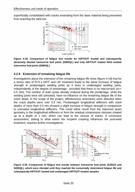
4.2.8 Additional abrasive blasting
Before applying a protection against corrosion it is necessary to clean the components through abrasive blasting. This process is carried out after a local post-weld treatment. The investigations conducted confirm that additional abrasive blasting after HiFIT or UIT treatment leads to further increase in fatigue strength. The Wöhler curves of the treated and blasted samples have an inclination of m = 8, which is significantly shallower than the ones of untreated samples and of the ones that were treated with a peening method but subsequently not blasted (figure 4-18). In particular the increased effectiveness of HiFIT or UIT treated and subsequently blasted samples, in comparison to only HiFIT or UIT treated welds, becomes apparent here, with numbers of cycles to failure greater than 106. The additionally abrasively blasted samples show a wider scatter of the results, which can arise from the not completely defined conditions of an abrasive blasting process. It is significant for practical application that the effectiveness created by the post-weld treatment is not diminished by abrasive blasting. On the contrary, it has a positive effect on the fatigue strength. Also adjacent areas of the material are
Effectiveness und mode of operation
Seite 20
superficially consolidated with cracks emanating from the base material being prevented from reaching the weld toe.
Load cycles [ ]
Str
ess r
ange [N
/mm
2]
Figure 4-18: Comparison of fatigue test results for HiFIT/UIT treated and subsequently abrasively blasted transverse butt joints (S690QL) and only HiFIT/UIT treated MAG welded transverse butt joints (S690QL)
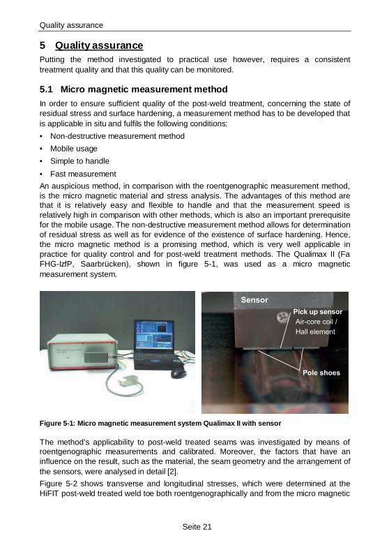
4.2.9 Extension of remaining fatigue life
Investigations about the extension of the remaining fatigue life show (figure 4-19) that for a stress ratio of R=0.1 HiFIT and UIT treatment leads to the same increase of fatigue strength in predamaged welding joints as it does in undamaged welding joints, independently of the degree of predamage - provided that there is no macrocrack (a>= 0.5 mm). The number of load cycles already endured during the predamage, while the welding joints were still untreated, have no influence on the remaining fatigue life of the notch detail. In the scope of the project, effectiveness restrictions were detected when the crack depths were over 0.5 mm. Predamaged longitudinal stiffeners with crack depths of more than 0.5 mm showed a slight increase in fatigue strength in comparison to untreated longitudinal stiffeners. This could either result from the improved seam geometry in the longitudinal stiffeners or from the residual compressive stresses created up to a depth of 1 mm, which can lead to the closure of cracks. A conclusive assessment, stating to what extent the incipient cracking influences the post-weld treatment, requires further investigations.
N [-]N [-]
Str
ess r
ange [N
/mm
2]
Str
ess r
ange [N
/mm
2]
Figure 4-19: Comparison of fatigue test results betw een transverse butt joints (S355J2 and S690QL), which were vibrated until they reached the numerically determined fatigue life and subsequently HiFIT/UIT treated and undamaged HiFIT/UIT treated samples
Quality assurance
Seite 21
5 Quality assurance Putting the method investigated to practical use however, requires a consistent treatment quality and that this quality can be monitored.
5.1 Micro magnetic measurement method In order to ensure sufficient quality of the post-weld treatment, concerning the state of residual stress and surface hardening, a measurement method has to be developed that is applicable in situ and fulfils the following conditions:
• Non-destructive measurement method
• Mobile usage
• Simple to handle
• Fast measurement
An auspicious method, in comparison with the roentgenographic measurement method, is the micro magnetic material and stress analysis. The advantages of this method are that it is relatively easy and flexible to handle and that the measurement speed is relatively high in comparison with other methods, which is also an important prerequisite for the mobile usage. The non-destructive measurement method allows for determination of residual stress as well as for evidence of the existence of surface hardening. Hence, the micro magnetic method is a promising method, which is very well applicable in practice for quality control and for post-weld treatment methods. The Qualimax II (Fa FHG-IzfP, Saarbrücken), shown in figure 5-1, was used as a micro magnetic measurement system.
Sensor
Pole shoes
Pick up sensor
Air-core coil /
Hall element
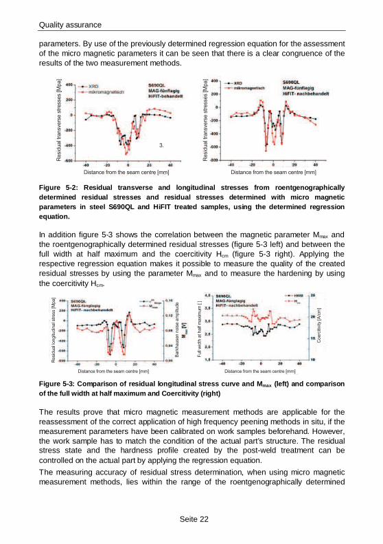
Figure 5-1: Micro magnetic measurement system Qualim ax II with sensor
The method’s applicability to post-weld treated seams was investigated by means of roentgenographic measurements and calibrated. Moreover, the factors that have an influence on the result, such as the material, the seam geometry and the arrangement of the sensors, were analysed in detail [2].
Figure 5-2 shows transverse and longitudinal stresses, which were determined at the HiFIT post-weld treated weld toe both roentgenographically and from the micro magnetic
Quality assurance
Seite 22
parameters. By use of the previously determined regression equation for the assessment of the micro magnetic parameters it can be seen that there is a clear congruence of the results of the two measurement methods.
Distance from the seam centre [mm]Distance from the seam centre [mm]
3.
Resi
dual t
ransv
ers
e s
tress
es
[Mpa]
Resi
dual t
ransv
ers
e s
tress
es
[Mpa]
Figure 5-2: Residual transverse and longitudinal str esses from roentgenographically determined residual stresses and residual stresses determined with micro magnetic parameters in steel S690QL and HiFIT treated samples, using the determined regression equation.
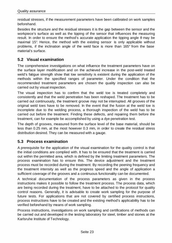
In addition figure 5-3 shows the correlation between the magnetic parameter Mmax and the roentgenographically determined residual stresses (figure 5-3 left) and between the full width at half maximum and the coercitivity Hcm (figure 5-3 right). Applying the respective regression equation makes it possible to measure the quality of the created residual stresses by using the parameter Mmax and to measure the hardening by using the coercitivity Hcm.
Distance from the seam centre [mm]Distance from the seam centre [mm]
Resi
dual l
ongitu
din
al s
tress
[M
pa]
Full
wid
th a
t half
maxi
mum
[ ]
Coerc
itivi
ty [A
/cm
]
Bark
hause
n n
ois
e a
mplit
ude
Figure 5-3: Comparison of residual longitudinal stre ss curve and M max (left) and comparison of the full width at half maximum and Coercitivity (right)
The results prove that micro magnetic measurement methods are applicable for the reassessment of the correct application of high frequency peening methods in situ, if the measurement parameters have been calibrated on work samples beforehand. However, the work sample has to match the condition of the actual part’s structure. The residual stress state and the hardness profile created by the post-weld treatment can be controlled on the actual part by applying the regression equation.
The measuring accuracy of residual stress determination, when using micro magnetic measurement methods, lies within the range of the roentgenographically determined
Quality assurance
Seite 23
residual stresses, if the measurement parameters have been calibrated on work samples beforehand.
Besides the structure and the residual stresses it is the gap between the sensor and the workpiece’s surface as well as the tipping of the sensor that influences the measuring result. In order to ensure the method’s accurate application the tipping angle θ may be maximal 15°. Hence, the method with the existing sensor is only applicable without problems, if the inclination angle of the weld face is more than 165° from the base material’s surface.
5.2 Visual examination The comprehensive investigations on what influence the treatment parameters have on the surface layer modification and on the achieved increase in the post-weld treated weld’s fatigue strength show that low sensitivity is existent during the application of the methods within the specified ranges of parameter. Under the condition that the recommended treatment parameters are chosen the quality inspection can also be carried out by visual inspection.
The visual inspection has to confirm that the weld toe is treated completely and consistently and that the weld penetration has been reshaped. The treatment has to be carried out continuously, the treatment groove may not be interrupted. All grooves of the original weld toes have to be removed. In the event that the fusion at the weld toe is incomplete due to the welding process, a thorough inspection of the weld has to be carried out before the treatment. Finding these defects, and repairing them before the treatment, can for example be accomplished by using a dye penetration test.
The depth of grooves, measured from the surface level of the base material, should be less than 0.25 mm, at the most however 0.3 mm, in order to create the residual stress distribution desired. They can be measured with a gauge.
5.3 Process examination A prerequisite for the application of the visual examination for the quality control is that the initial conditions are complied with. It has to be ensured that the treatment is carried out within the permitted area, which is defined by the limiting treatment parameters. The process examination has to ensure this. The device adjustment and the treatment process must be recorded during the treatment. By recording the peening frequency and the treatment intensity as well as the progress speed and the angle of application a sufficient coverage of the grooves and a continuous functionality can be documented.
A technical documentation of the process parameters as given in the process instructions makes it possible to follow the treatment process. The process data, which are being recorded during the treatment, have to be attached to the protocol for quality control reasons. Generally, it is advisable to create work sampling for the purpose of future tests. For applications that are not covered by certified process instructions, process instructions have to be created and the existing method’s applicability has to be verified beforehand by means of work sampling.
Process instructions, investigations on work sampling and certifications of methods can be carried out and developed in the testing laboratory for steel, timber and stones at the Karlsruhe Institute of Technology.
Quality assurance
Seite 24
5.3.1 Treatment parameters
The treatment parameters, which ensure a sufficient quality of the post-weld treatment, were determined and recorded on the basis of the results of the investigations on the notch details and materials within the scope of this research project. For more complex structures with differing seam details, materials or with limited accessibility, to which the results are not directly applicable, the treatment parameters have to be verified and newly determined by means of the work sampling. The micro magnetic measurement method can be used to check the chosen parameters and the residual stresses and hardenings created.
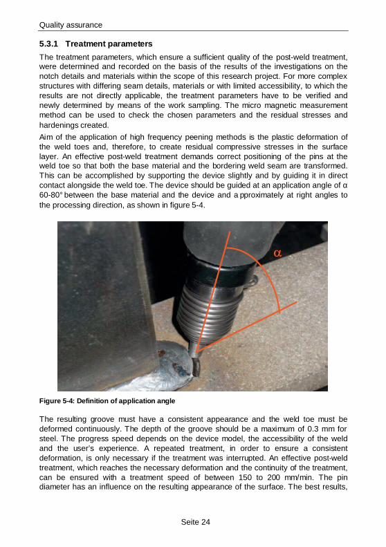
Aim of the application of high frequency peening methods is the plastic deformation of the weld toes and, therefore, to create residual compressive stresses in the surface layer. An effective post-weld treatment demands correct positioning of the pins at the weld toe so that both the base material and the bordering weld seam are transformed. This can be accomplished by supporting the device slightly and by guiding it in direct contact alongside the weld toe. The device should be guided at an application angle of α 60-80° between the base material and the device and a pproximately at right angles to the processing direction, as shown in figure 5-4.
Figure 5-4: Definition of application angle
The resulting groove must have a consistent appearance and the weld toe must be deformed continuously. The depth of the groove should be a maximum of 0.3 mm for steel. The progress speed depends on the device model, the accessibility of the weld and the user’s experience. A repeated treatment, in order to ensure a consistent deformation, is only necessary if the treatment was interrupted. An effective post-weld treatment, which reaches the necessary deformation and the continuity of the treatment, can be ensured with a treatment speed of between 150 to 200 mm/min. The pin diameter has an influence on the resulting appearance of the surface. The best results,
Quality assurance
Seite 25
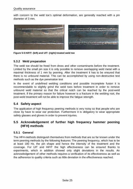
with concern to the weld toe’s optimal deformation, are generally reached with a pin diameter of 3 mm.
Figure 5-5 HiFIT- (left) and UIT- (right) treated we ld toe
5.3.2 Weld preparation
The weld toe should be freed from dross and other contaminants before the treatment. Limited by the small pin size it is only possible to remove overlapping weld metal with a maximal thickness of 1 mm by peening. After the treatment it has to be ensured that there is no unbound material. This can be accomplished by using non-destructive test methods such as the dye penetration test
In the event of undefined welding conditions and possible incomplete fusion it is recommendable to slightly grind the weld toes before treatment in order to remove unbound weld material so that the critical notch can be reached by the post-weld treatment. If the primary reason for failure however is a fracture in the welding root, the post-weld treatment will not be able to improve the fatigue strength.
5.4 Safety aspect The application of high frequency peening methods is very noisy so that people who are close by have to wear ear protection. Furthermore it is obligatory to wear appropriate safety glasses and gloves in order to prevent injuries.
5.5 Acknowledgement of further high frequency hammer peening (HFH) methods
5.5.1 General
The HFH-methods distinguish themselves from methods that are so far known under the term peening methods by the following features: The peening frequency, which has to be at least 180 Hz, the pin shape and hence the intensity of the treatment and the coverage. For UIT and HiFIT the high effectiveness can be ensured thanks to experiments, which in addition showed only slight deviations in the results. An acknowledgement of other methods requires a verification of its effectiveness as well as the adherence to quality criteria such as little deviation in the effectiveness reached.
Quality assurance
Seite 26
5.5.2 Conditions for acknowledgement
• The method causes a verifiable clear increase in the fatigue strength of welded joints due to a mechanical surface layer modification.
• The surface layer modifications created show only slight deviation within the treatment within the specified treatment parameters and the certified areas of application.
• The deviation of residual stress values after treatment may be at a maximum of 10-15%, with treatment parameters within the specified field of parameters, (both in the surface layer as well as the residual stress in the depth).
• Maximum deviation of surface layer hardness after treatment: 10%.
• Maximum deviation of depth of grooves: 20%
• A sufficient number of hammer hits, all of the same intensity in one place, causes a stable adjustment of the surface layer condition, which is adjusted by the ratio of peening frequencies to progress speed.
• The method causes a deformation of the weld toe; weld penetrations must be firmly removed.
• Inspection criteria such as, for example, the depth of groove, which have to show distinct characteristics of a successful treatment, must be specified. This requires a verification of the criteria specified and the fatigue strength and/or the surface layer condition.
• The manufacturer must provide equipment for the devices that allow the user to constantly verify the process of treatment.
• The residual stress behaviour caused by quasi-static strain must be analysed and it has to be verified that the residual stress is consistent even with quasi-static strain up to values of nominal yield strength.
• The dependence of the effectiveness on the material strength must be analysed whereupon it has to correlate with the results of the acknowledged method.
5.5.3 Experimental verification
To experimentally verify the effectiveness of post-weld treatment methods the following investigations have to be carried out and the sufficient quality has to be proven.
5.5.4 Investigations on alterations in seam geometry
Examination of removal of the weld penetration at butt welds and fillet welds (visual examination). Examination of depth of groove (max. 0.3 mm)
5.5.4.1 Investigations on distribution of residual stresses
Base material:
• Measurement on the surface (roentgenographic)
Depth measurement (bore hole method + electrolytic abrasion and x-ray measurements)
Parameter:
• Strength class
Quality assurance
Seite 27
• Standard parameter: frequency, intensity, progress speed
• Increased progress speed
Weld toe:
• Measurement on the surface (roentgenographic)
• Parameter:
• Strength class
• Standard parameter: frequency, intensity, progress speed
5.5.4.2 Fatigue tests for analysing the fatigue strength of post-treated welds
Parameter:
• Strength class
• Treatment with standard parameters:
• Frequency, intensity, progress speed
• Stress relation: R=0.1, R=0.5 and R=-1, 12 samples per test
• Notch detail, sheet thickness, welding method: 135, 136, 114, 111, 121
5.6 Measures for quality assurance The HFH devices must be subject to test and production equipment monitoring. Maintenance intervals have to be stipulated.
The monitoring of the compliance with the parameters has to be ensured via a measurement system.
Adequate training and process instructions for user training have to be ensured by the manufacturer or by others.
5.6.1 Manufacturer qualification and user training
Applying the method correctly requires experience in the application. For this reason the user company must be qualified. This implies not only adequate company equipment and process flow but also qualified supervisory and operating staff. Proper application ought to be shown and taught within the scope of the training for users. Successful attendance has to be proven in an exam. Both the user and the user company have to be tested and monitored by a verified test centre.
Design concept
Seite 28
6 Design concept On the basis of experimental and numerical investigations a generally valid design approach was developed and verified by means of the investigation’s results. The design concept developed has been appropriately simplified so that it allows an optimised design of the parts for the engineers using the nominal stress approach as well as the engineers using local concepts under careful consideration of positive effects of post-weld treatment. The concept is presented in the following to form the basis for a draft for standards and regulations.
6.1 General The developed design approach serves for the assessment of welds that are post-weld treated with high frequency peening methods. State of the art design concepts provided the background for this design approach. The improvement factor stated in the following can be applied to nominal, structural and notch stress approaches. During the treatment the valid quality requirements must be considered. The validity of the design rules is currently limited to sheet thicknesses >8 mm. It is recommended to apply the design concept only if the number of load cycles N reaches N≥105. The design concept is applicable to all areas that are treated with high frequency peening methods. The improvement described is only applicable to the cross section of the weld toe in welded parts. Other untreated cross sections that are potentially at risk must still be designed according to conventional methods.
6.1.1 Proceedings
The statistically evaluated test results of the BMBF Project REFRESH and of the AIF Project P620 [5] form the basis of the design approach.
The yield strength of the base material as well as the stress ratio have turned out to be the parameters with essential influence on the effectiveness of the post-weld treatment methods. Both parameters are taken into consideration with suitable factors. Geometrical influences are appraised by specification of the notch detail in the style of existing catalogues with fatigue detail categories.
6.1.2 Inclination of the Wöhler curve
Differing from previous Wöhler curves the inclination determined is m=5. This inclination reflects the shallower Wöhler curve progression found in experiments with post-weld treated notch details, which had been treated with high frequency peening methods.
6.1.3 Factor K HP
The theoretical fatigue strength of post-weld treated welds ∆σc,HP results from the fatigue strength of untreated welds ∆σc (FAT) under consideration of the factor KHP.
∆σc,HP = KHP * ∆σc
with KHP = k0 * kRe * kR
k0 Improvement factor
kRe Material factor depending on the yield strength Re
Design concept
Seite 29
kR Strain factor depending on the stress ratio R, referring to the strain applied from the outside. The state of residual stresses is not included in this stress ratio.
6.1.3.1 Improvement factor k0
The improvement factor k0, which is generally given, is based on the results of experimental investigations with a stress ratio of R=0.1 and a yield strength of R=355 N/mm². It is determined as follows:
k0 = 1.6
The improvement factor k0 is cautiously gauged on the basis of test results for the notch details butt weld, transverse rib and longitudinal stiffener by drawing on the lowest test value (lower limit of scatter). The notch details are based on variations in manufacturing and material. It is not assumed that k0 depends on the geometry. This is why only the lowest value is applied for all details.
6.1.3.2 Material factor kRe
In order to allow for the post-weld treatment’s higher effectiveness with high strength materials the factor of correction kRe is specified, considering the yield strength influence for yield strengths 355 N/mm² < Re <= 690 N/mm²:
KRe = 1 + 0,6 * (1 – 355/Re)
This approach approves a maximum improvement by 30% for steel S690QL. The higher effectiveness for steel S690QL is deduced from the ratio of the experimentally determined fatigue strength of HiFIT/UIT treated and untreated weld details with steel qualities from S690QL to S355J2.
If the improvement factor for the fatigue strength with 2*106 load cycles is taken into account according to this design concept, a Wöhler curve inclination of m=3 in the area of finite life fatigue strength may be applied for steel S690QL with a stress ratio1 of R<0.1.
6.1.3.3 Strain factor kR
For stress ratios R<0.1 a reduction factor must be applied, which was determined by means of the ratio of the experimentally determined fatigue strength of HiFIT and UIT treated transverse butt joints for the stress ratios R=0.1 and R=0.5. So far, experimental results of stress ratios of up to R=0.5 exist. The regulation is therefore only valid up to this stress ratio.
kR = 1.075-0.75*R 0.1<=R<=0.5
kR=1.0 R<0.1
6.1.4 Excessive load
Previous investigations on the reduction of residual stresses and on the influence of quasi-static compressive and tensile stress amounting to the value of yield strength on the fatigue strength do not show a negative influence. Further influences potentially reducing residual stresses as for example heat treatment, mechanical treatment etc. are to be avoided.
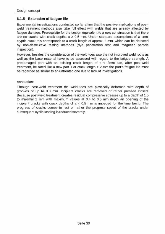
Design concept
Seite 30
6.1.5 Extension of fatigue life
Experimental investigations conducted so far affirm that the positive implications of post-weld treatment methods also take full effect with welds that are already affected by fatigue damage. Prerequisite for the design equivalent to a new construction is that there are no cracks with crack depths a ≥ 0.5 mm. Under standard assumptions of a semi elyptic crack this corresponds to a crack length of approx. 2 mm, which can be detected by non-destructive testing methods (dye penetration test and magnetic particle inspection).
However, besides the consideration of the weld toes also the not improved weld roots as well as the base material have to be assessed with regard to the fatigue strength. A predamaged part with an existing crack length of c < 2mm can, after post-weld treatment, be rated like a new part. For crack length > 2 mm the part’s fatigue life must be regarded as similar to an untreated one due to lack of investigations.
Annotation:
Through post-weld treatment the weld toes are plastically deformed with depth of grooves of up to 0.3 mm. Incipient cracks are removed or rather pressed closed. Because post-weld treatment creates residual compressive stresses up to a depth of 1.5 to maximal 2 mm with maximum values at 0.4 to 0.5 mm depth an opening of the incipient cracks with crack depths of a < 0.5 mm is impeded for the time being. The progress of cracks comes to rest or rather the progress speed of the cracks under subsequent cyclic loading is reduced severely.
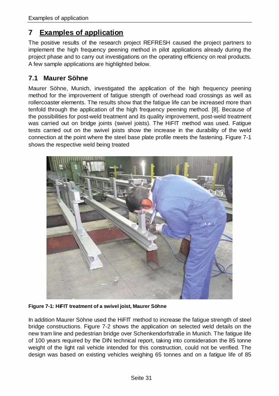
Examples of application
Seite 31
7 Examples of application The positive results of the research project REFRESH caused the project partners to implement the high frequency peening method in pilot applications already during the project phase and to carry out investigations on the operating efficiency on real products. A few sample applications are highlighted below.
7.1 Maurer Söhne Maurer Söhne, Munich, investigated the application of the high frequency peening method for the improvement of fatigue strength of overhead road crossings as well as rollercoaster elements. The results show that the fatigue life can be increased more than tenfold through the application of the high frequency peening method. [8]. Because of the possibilities for post-weld treatment and its quality improvement, post-weld treatment was carried out on bridge joints (swivel joists). The HiFIT method was used. Fatigue tests carried out on the swivel joists show the increase in the durability of the weld connection at the point where the steel base plate profile meets the fastening. Figure 7-1 shows the respective weld being treated
Figure 7-1: HiFIT treatment of a swivel joist, Maure r Söhne
In addition Maurer Söhne used the HiFIT method to increase the fatigue strength of steel bridge constructions. Figure 7-2 shows the application on selected weld details on the new tram line and pedestrian bridge over Schenkendorfstraße in Munich. The fatigue life of 100 years required by the DIN technical report, taking into consideration the 85 tonne weight of the light rail vehicle intended for this construction, could not be verified. The design was based on existing vehicles weighing 65 tonnes and on a fatigue life of 85
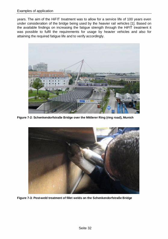
Examples of application
Seite 32
years. The aim of the HiFIT treatment was to allow for a service life of 100 years even under consideration of the bridge being used by the heavier rail vehicles [1]. Based on the available findings on increasing the fatigue strength through the HiFIT treatment it was possible to fulfil the requirements for usage by heavier vehicles and also for attaining the required fatigue life and to verify accordingly.
Figure 7-2: Schenkendorfstraße Bridge over the Mittl erer Ring (ring road), Munich
Figure 7-3: Post-weld treatment of fillet welds on t he Schenkendorfstraße Bridge
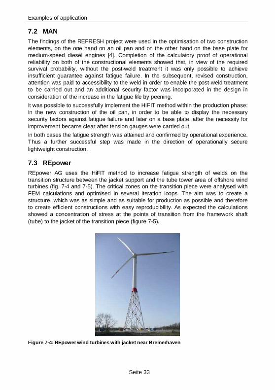
Examples of application
Seite 33
7.2 MAN The findings of the REFRESH project were used in the optimisation of two construction elements, on the one hand on an oil pan and on the other hand on the base plate for medium-speed diesel engines [4]. Completion of the calculatory proof of operational reliability on both of the constructional elements showed that, in view of the required survival probability, without the post-weld treatment it was only possible to achieve insufficient guarantee against fatigue failure. In the subsequent, revised construction, attention was paid to accessibility to the weld in order to enable the post-weld treatment to be carried out and an additional security factor was incorporated in the design in consideration of the increase in the fatigue life by peening.
It was possible to successfully implement the HiFIT method within the production phase: In the new construction of the oil pan, in order to be able to display the necessary security factors against fatigue failure and later on a base plate, after the necessity for improvement became clear after tension gauges were carried out.
In both cases the fatigue strength was attained and confirmed by operational experience. Thus a further successful step was made in the direction of operationally secure lightweight construction.
7.3 REpower REpower AG uses the HiFIT method to increase fatigue strength of welds on the transition structure between the jacket support and the tube tower area of offshore wind turbines (fig. 7-4 and 7-5). The critical zones on the transition piece were analysed with FEM calculations and optimised in several iteration loops. The aim was to create a structure, which was as simple and as suitable for production as possible and therefore to create efficient constructions with easy reproducibility. As expected the calculations showed a concentration of stress at the points of transition from the framework shaft (tube) to the jacket of the transition piece (figure 7-5).
Figure 7-4: REpower wind turbines with jacket near B remerhaven
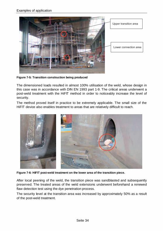
Examples of application
Seite 34
Upper transition area
Lower connection area
Figure 7-5: Transition construction being produced
The dimensioned loads resulted in almost 100% utilisation of the weld, whose design in this case was in accordance with DIN EN 1993 part 1-9. The critical areas underwent a post-weld treatment with the HiFIT method in order to noticeably increase the level of security.
The method proved itself in practice to be extremely applicable. The small size of the HiFIT device also enables treatment to areas that are relatively difficult to reach.
Figure 7-6: HiFIT post-weld treatment on the lower a rea of the transition piece.
After local peening of the weld, the transition piece was sandblasted and subsequently preserved. The treated areas of the weld extensions underwent beforehand a renewed flaw detection test using the dye penetration process.
The security level at the transition area was increased by approximately 50% as a result of the post-weld treatment.
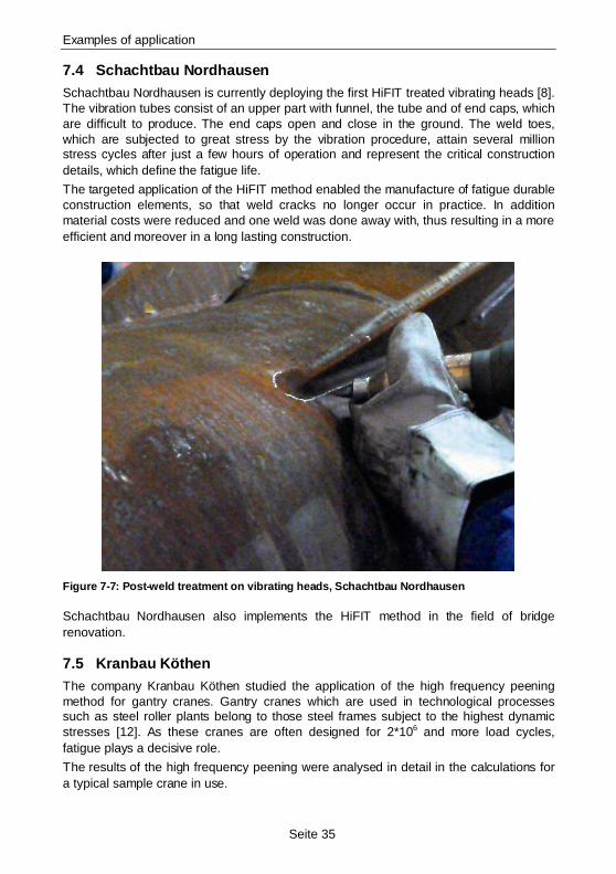
Examples of application
Seite 35
7.4 Schachtbau Nordhausen Schachtbau Nordhausen is currently deploying the first HiFIT treated vibrating heads [8]. The vibration tubes consist of an upper part with funnel, the tube and of end caps, which are difficult to produce. The end caps open and close in the ground. The weld toes, which are subjected to great stress by the vibration procedure, attain several million stress cycles after just a few hours of operation and represent the critical construction details, which define the fatigue life.
The targeted application of the HiFIT method enabled the manufacture of fatigue durable construction elements, so that weld cracks no longer occur in practice. In addition material costs were reduced and one weld was done away with, thus resulting in a more efficient and moreover in a long lasting construction.
Figure 7-7: Post-weld treatment on vibrating heads, Schachtbau Nordhausen
Schachtbau Nordhausen also implements the HiFIT method in the field of bridge renovation.
7.5 Kranbau Köthen The company Kranbau Köthen studied the application of the high frequency peening method for gantry cranes. Gantry cranes which are used in technological processes such as steel roller plants belong to those steel frames subject to the highest dynamic stresses [12]. As these cranes are often designed for 2*106 and more load cycles, fatigue plays a decisive role.
The results of the high frequency peening were analysed in detail in the calculations for a typical sample crane in use.
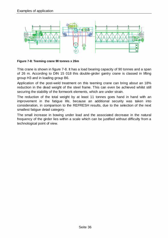
Examples of application
Seite 36
Figure 7-8: Teeming crane 90 tonnes x 26m
This crane is shown in figure 7-8. It has a load bearing capacity of 90 tonnes and a span of 26 m. According to DIN 15 018 this double-girder gantry crane is classed in lifting group H3 and in loading group B6.
Application of the post-weld treatment on this teeming crane can bring about an 18% reduction in the dead weight of the steel frame. This can even be achieved whilst still securing the stability of the formwork elements, which are under strain.
The reduction of the total weight by at least 11 tonnes goes hand in hand with an improvement in the fatigue life, because an additional security was taken into consideration, in comparison to the REFRESH results, due to the selection of the next smallest fatigue detail category.
The small increase in bowing under load and the associated decrease in the natural frequency of the girder lies within a scale which can be justified without difficulty from a technological point of view.
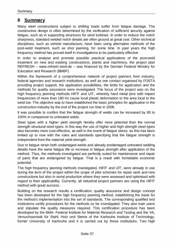
Summary
Seite 37
8 Summary Many steel constructions subject to shifting loads suffer from fatigue damage. The constructive design is often determined by the verification of sufficient security against fatigue, such as in supporting structures for wind turbines. In order to reduce the notch sharpness, standard welded notch details are often ground at great cost. Other technical disciplines, such as vehicle manufacture, have been using alternative methods of the post-weld treatment, such as shot peening, for some time. In past years the high frequency method has proved itself in investigations to be particularly effective.
In order to analyse and promote possible practical applications of the post-weld treatment on new and existing constructions, plants and machinery, the project plan REFRESH – www.refresh-steel.de – was financed by the German Federal Ministry for Education and Research (BMBF).
Within the framework of a comprehensive network of project partners from industry, federal agencies and research institutions, as well as one contact organised by FOSTA providing project support, the application possibilities, the limits for application and the methods for quality assurance were investigated. The focus of the project was on the high frequency peening methods HiFIT and UIT, whereby hard metal pins with impact frequencies of more than 180 Hz cause local plastic deformation to the area local to the weld toe. The objective was to have established the basic principles for application in the construction industry by the end of the project run time in 2009.
It was possible to confirm that the fatigue strength of welds can be increased by 80 to 100% in comparison to untreated welds.
Steel types with a higher yield strength hereby offer more potential than the normal strength structural steel types. In this way the use of higher and high strength steel types also becomes more cost-effective, as well in the event of fatigue stress, as this has been limited up to now with the rules and standards specifying that the fatigue strength is independent from the material yield strength.
Due to fatigue strain both undamaged welds and already predamaged untreated welding details have the same fatigue life or increase in fatigue strength after application of the method. Thus, the methods investigated are perfectly suited for maintenance and repair of parts that are endangered by fatigue. That is a result with formidable economic potential.
The high frequency peening methods investigated, HiFIT and UIT, were already in use during the term of the project within the scope of pilot schemes for repair work and new constructions but also in serial production where they were assessed and optimised with regard to their applicability. Currently, all industrial project partners are using the HiFIT method with great success.
Building on the research results a certification, quality assurance and design concept has been developed for the high frequency peening method, establishing the basis for the method’s implementation into the set of standards. The corresponding qualified test institutions certify procedures for the methods so far investigated. They also train users and stipulate the quality measures required. This certification procedure has been developed by the BMA- Federal Institute for Material Research and Testing and the VA, Versuchsanstalt für Stahl, Holz und Steine of the Karlsruhe Institute of Technology, former University of Karlsruhe and it is carried out by these institutions. Two high
Summary
Seite 38
frequency peening methods, HiFIT and UIT, so far fulfil the certification requirements, which is confirmed in a quality certification jointly issued by the BAM and VA.
The quality assurance system developed makes it possible to control the quality of post-weld treatment, similar to the control of welding processes. It is possible to ensure the effective application of the post-weld treatment while records and documentations make it possible to verify the whole process after it has been carried out by trained staff according to certified procedures.
The design concept allows a simple and cautious service life calculation of post-weld treated welds due to uprating of the fatigue detail category and allowing for an adjusted inclination of the Wöhler curve.
Currently national and international committees are working on an implementation of the results into common standards. Therefore, in the future it will not only be possible to apply these methods within the frame of defined limits but also to calculate and design them.
Summary
Seite 39
List of references
Summary
Seite 40
Summary
Seite 41
Acknowledgements The research and development project REFRESH was subsidised with funds from the German Federal Ministry of Education and Research (BMBF) within the conceptual framework “Research for future production” and attended by the Research Centre Karlsruhe, division Production and Manufacturing Technology (PTKA-PFT) as the body responsible for the project. The project partners would like to thank the German Federal Ministry of Education and Research (BMBF) for the financial support of the project. In particular the partners would like to express their gratitude to the Research Centre Karlsruhe (PTKA), division Production and Manufacturing Technology (PFT), as well as to all the members of the industrial research group. Sincere thanks are also extended to the consortium of the Dillinger Hüttenwerke, the Ilsenburger Grobblech GmbH and the ThyssenKrupp Steel AG for their substantial material donations.
The authors would also like to especially thank Mr. Dr.-Ing. Thomas Nitschke-Pagel from the Institute of Joining and Welding at the Technical University in Braunschweig for his advice and his intensive support of the project.

Forschungsvereinigung Stahlanwendung e. V.im Stahl-ZentrumPostfach 10 48 42 • 40039 DüsseldorfSohnstr. 65 • 40237 Dü[email protected] • www.stahlforschung.de
!