fortran introductory programmer's manual. section i. · pdf filefortran introductory...
TRANSCRIPT
March 20, 1957
FORTRAN INTRODUCTORY PROGRAMMER'S MANUAL
SECTION I
This first section of the forthcoming Introductory Pro
grammer's Manual is being distributed in this form to permit its
early use for teaching purposes. The subsequent sections will be
distributed as they become available. Finally, the entire manual
will be distributed in type- set form.
This material may be reproduced as desired.
Programming Research Department
International Business Machines Corporation
590 Madison Avenue
New York, New York

INTRODUCTION
This manual is intended to inform its readers in as Goncise a
form as possible how a large-scale electronic calculator (the IBM
Type 704) may be employed to produce answers to many problems
in engineering, physics, and other related technical fieids. No c
prerequisite ·knowledge of computing technology or techniques on
the part of the reader is assumed.
In order to clarify what the 704 can do and what it cannot do,
consider, for example, the problem of finding the roots of a
quadratic equation. The 704 cannot be given an equation of the
form
3x2 + 1. 7x - 31. 92 = 0
and asked to find its roots. The machine, however, can be
directed to compute the value of
( -'1. 7 + v' (1.7)2 - 4 (3)(-31. 92) / 2(3)
which gives one of the roots of the preceding equation. That is. the
704 must be told how to find the answer. It will do the work.
Once the 704 has been told how to solve a problem. it can take

2.
in data at a rate exceeding 1000 numbers per minute, perform
arithmetic steps at an approximate rate of 10,000 per second,
and print results at a rate of about 750 per minute. Thus the 704
can do in minutes calculations which would otherwise require
weeks or months to do.
Unfortunately, electronic computers, the 704 included, have
been designed to respond to a special type of language which takes
considerable effort to learn. It is this "machine language" which,
in the end, must be used to tell the machine what steps to perform
to solve a problem. However, it is not necessary to learn the
language ,of the machine. Instead, a simpler language for directing
the 704 will be presented in the succeeding sections of this manual.
It is called the FORTRAN language.
The FORTRAN statements which describe how to solve a
problem are not directly intelligible to the 704. However, the 704
can be told exactly how to translate a statement in FORTRAN language
into machine language. The FORTRAN System is a large set of
machine language instructions which causes the 704 to translate
the FORTRAN statements into instructions in machine language.
The 704 can later carry out these machine language instructions
3.
and do the actual computing job. The name FORTRAN comes from
"FORmula TRANslation" because many of the statements to be
translated look just like algebraic formulas.
In order to avoid having to read and learn more than is necess
ary to solve the problems of immediate interest, three systems
will be described, each one permitting the convenient description
of more complex problem solving procedures than its predecessor.
Each system is complete in itself. Every statement which can be
made in System I can also be made in Systems II and III. Al1
statements in System II are valid in System III. Thus the description
of System II simply consists of showing how to write a few state
ments not described in System I; etc. It is hoped that this progress
by easy stages wil1 result in a brief and clear presentation.
By using only the statements contained in System 1, it will be
possible to direct the 704 to take numbers from a card reader,
combine them according to formulas involving arithmetic operations
and functions such as sine, square root, log, etc., and final1y print
the results. System I also contains statements which can cause the
704 to make tests and follow different directions depending on the
outcome of the tests.
System II, in addition to the facilities of System I which make
4.
it possible to handle individual numbers, provides for treating
the elements of vectors or lists of numbers in a systematic,
repetitive manner. System II also provides for the possibility of
defining and using functions which are peculiar to the problem
being solved. It is also possible to direct the 704 to take input
information from magnetic tapes and record output information on
them. Since information can be placed on magnetic tapes and
printed fromthem by equipment separate from the 704 (card-to
tape and tape-to-printer), it is possible for the 704 to take in
data from tape and record results on tape at a much greater speed
than by reading data cards and printing results directly. By using
magnetic tape for input and output, it is possible to read or write
more than 900 numbers per second. Greater flexibility in the format
of input and output data is also provided iIi System II.
System III adds to these facilities the ability to handle mat:rices
and three dimensional arrays of numbers, and nlore complex
repetitive procedures. Means are also provided for further con"
trolling the flow of control within the program.
Even System III does not include all of the facilities offered
by the complete FORTRAN System. Complete information about
FORTRAN is available in the FORTRAN Programmer's Reference

5.
Manual. the complete title of which is The FORTRAN Automatic
Coding System for the IBM 704 EDPM. This manual can be
ordered through your local IBM office.
It was stated earlier that this manual was going to describe
how to use the 704. However. it will not explain the details of
button pushing, tape loading, card feeding, and other related
operations needed to get the 704 working on a problem. It has
been assumed that the 704 will be operated by a computing center.
At the computing center, the FORTRAN statements are first·
transcribed onto punched cards. The statements will be punched
exactly as they have been written, each letter, digit, or punctuation
mark resulting in one or a combination of holes in a single column
of a card. These cards are then put in the card-reading mechanism
of the 704. Instructions already in the machine cause the 704 to start
reading the FORTRAN statements from the cards. The 704 then
operates for a few minutes, translating the FORTRAN statements
which have been supp~ied to it into machine language instructions.
These machine instructions are recorded on punched cards by the
704. This new set of cards now contains a machine language "pro
gram" which can be entered into the 704 any number of times, each
time causing the 704 to carry out the procedure specified by the

6.
priginal series of FOR 'fRAN statements.
Before descdbing FORTRAN Systems I, II, and III, a short
description of the 704 iteeH may be of interest. The 704 consists
of an arithmetic and logical unit, a storage unit capable of storing
4,000, 8,000 or 32,000 numbers, magnetic tape units and magnetic
drum units for holding iruormation exceeding the capacity of the
storage unit, a card reader, a card punch, and a printer. In addi
tion there is a control unit which directs the flow of information
between these various units in accordance with instructions in the
storage unit.
Most calculations performed by the 704 ~re carried out in
"floating point" form. That is, numbers are represented in the
machine in a form analogous to floating decimal form and the
results produced by the arithmetic unit are usually in this form.
For example: calculation of the product
5xO.0037
would be carried out in a' form similar to
(.5000 OOOOx H)l) x (.3700 OOOOx 10-2 )= (.1850 OOOOx 10- 1).
This would be the case e\l"en though the numbers were entered as
5.0 and 0.' 0037 and the result were printed as 0.0185. All floating
7.
point numbers in the 704 are carried to about 8 significant
decimal digits. Numbers outside the range 10- 38 to 1038 (other
than zero) cannot normally be accommodated.
'In the following sections of this manual, Section I describes
System 1, Sections land II describe System II, and Sections I, II
and In taken together describe System III. The division of the
'subject matter into three systems has been made to permit the
gradual introduction of new material. It is hoped that the end
of a section will not be regarded as a real boundary, but rather
that the mastery of one section will result in a desire to in
vestigate the next.
Please remember that the FORTRAN language statements
are going to be translated by a. machine before the problem is
ready to be run. The machine has. no ability to understand what
was meant; it can only translate what was written. Therefore,'
the omission of a single decimal point or operation symbol may
make a FORTRAN statement unintelligible and incapable of being
translated correctly. For this reason the rules which must be
observed in writing FORTRAN statements should be followed
carefully. In devising the FORTRAN System considerable effort
was devoted to making these rules consistent and having them
8.
conform to common usage wherever possible. A number of
examples have been provided to illustrate these rules without
having to include specific statements of them in the text. It is
hoped. for example. that a fairly complete notion of what a
legitimate statement in System I must look like will be con
veyedby the examples in Section I., A check-list of things-not
to-write appearing at the end of each, sectio~ should answer any
remaining questions. Some of the rules in the check-list will
not have been explicitly stated elsewhere.

9.
SECTION 1°
Introduction
By way of introduction, consid~r the quadratic equation
example presented previously. The algebraic representation
could be written
-B + ../B2 - 4AC root =----------2-A---------
where A = +3
B= +1.7
C = -31.92.
The complete FORTRAN progx:am which describes this calculation
and provides for printing the result may be written in six separate
statements as follows:
A = 3.
B = 1. 7
C=-31.92
ROOT = (- B + SQRTF (B**2~ - 4. *A*C))/(2. *A)
PRINT I, ROOT
STOP
10.
The first statement means lIassign the value 3. to the variable
A". The next two statements have a 'similar meaning. The fourth
statement means "evaluate the expression on the right side and
assign the ,x-esult to the yariable 'ROOT'''. The last statement
instructs the computer to stop.
Notice the sequential nature of the program. The computer
executes instructions in the same order as the order of the state
ments. For example. if the fourth statement were to be moved
up and made the first statement, then the computer would evaulate
'ROOT' b~f()re obtaining the desired values of A. B. and C.
iROOT' would. therefore, be evaluated using some arbitrary,
unknown values for these variables.
(The above example was written to illustrate the use of variables.
However, the same result could be obtained by writing
ROOT = (-1. 7+SQRTF (1. 7**2. -4. *3. *(-31. 92))/(2.*3.),'
PRINT 1. ROOT
STOP
in which the actual numerical values appear in the statement des
cribing the evaluation of 'ROOT'. )
In order to describe more com,pletelythe·types of statements
inciuded'in System I. each of the statements used in System I will

be considered in greater detail.
Arithmetic Formulas
11.
The first four statements in the above example are called
arithmetic formulas. As is evident, an" arithmetic formula looks
like a simple statement of equality. The left side of the equality
is a variable, and the right side is an expression which may
involve parentheses and symbols for operations, constants,
variables, and functions, combined in accordance with a set of
rules much like that of ordinary algebra .
. The fourth statement in the example illustrates the use of
the five basic operations in the system. The symbols "+" and
"_II are used in the usual way for addition and subtraction.· The
symbol "*" is used for multiplication, and "/" is used for division.
The last basic operation, A to the power B (AB) is written
Notice that in writing a constant, a decimal point must be
included. This is necessary in order to indicate to the computer
that the number is to be treated in floating point form, since all
calculations in System I are carried out in floating point arithmetic.
Just as in ordinary notation.
A>'.o:cB>:CC + D>!c>''''E/F - G

will be interpreted to mea.n
(ABC) + (DE/F) .. O.
12.
That is, if pa,l"enthese ...... not used to specify the order of opel"ations,
this order. from inside t~ outside', is assumed to be:
( 1) exponentiation
, '(2) multiplicaUon and division
(3) addition and lubtraction
P~rentheses a're used in,tlJe usual way to specify order. For
example
(A(B + C))D
ma y be written in FOR TitAN as
(A*(B + C»**D.
There a ~e just three eXC'eptiona to the ordinary rules of ma,the
mati cal notation. These ,are:
(1) In ordinary notation "AB" means "A. B" or "A times
B". However. "AB" never means "A*Bij in FORTRAN'.
The multiplication operation symbol cannot be omitted.
(2) Ordinarily .. expressions like "A/B· C" and "A/BI e"
are considered ambiguous. However, such expressions
~ allowe4 in FORTRAN and will be interpreted as

follows:
A/B*C means (A/B)*C
A*B I C means (A*B) I C
AlBIC means (A/B)/C
A/B/C*D*E/F means ««A/B)/C)*b)*E)/F.
13.
That is, the order of operations is simply taken
to be from left to right. in the same way that , .
A+B-C+D-E
means
«(A+B) - C)+D) - E.
(3) The expression "ABC" is often considered meaningful.
However. the corresponding FORTRAN expression
"A**B**C" is not allowed. It should be written as
"(A**B)**C" or "A**(B**C)", whichever is desired.
Besides the ability to indicate constants (like "3.57" and "2. "),
variables (like "A" and "ROOT"), and operations (like "_" and
"*"), it is also possible to use functions. In the above example
"SQRTF( )" indicates the square root of the expression in
parenthe se s.
Since the number of possible functions is very large. each
704 computing center will have its own list of available functions.
with information about their use. Only functions given in this
list should be used and they should be referred to exactly as irt-
dicated •.
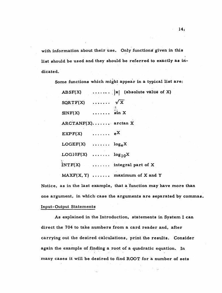
Some functions which might appear in a· typical list are:
ABSF(X)
SQRTF(X)
SINF(X) .......
(absolute valUe of X)
.;x ,:1 j.,,1 -
sin X
ARCTANF(X) ..•.•.•. arctan}(:
EXPF(X) . . . . . ' .. LOGEF(X)
LOG10F(X) \ '
iNTF(X) integral part of X
MAXF(X, Y) maximum of X and Y
Notice, as in the last example, that a 'function may have more than
one argument, in which-. case the arguments are separated by commas.
Input- Output Statements
As explained in the Introduction, statements in System I can
direct the 704 to take numbers from a card reader and, after
carrying out the desired calculations, print the results. Consider
again the example of~iIld,ing a root of a quadratic equation. In
many cases it will be desired to find ROOT for a number of sets

15.
of values of A, B, and C. In that case the 704 would have to be
directed to read a card in which values for A, B, and C have been
punched, compute the value of ROOT, and print ROOT (along with
A,B, and C), read another card with different values for A, B,
and C, compute and print the corresponding value of ROOT and
so on. In this case, the FORTRAN program could be written
10 READ 1, A, B, C
ROOT = (-B+SQRTF(B**2. -4. *A*C»/(2. *A)
PRINT 1, A, B, C, ROOT
GO TO 10
The first statement (which has been given the number 10 for
reference purposes) causes the 704 to read the first card from
the deck in the hopper of the card reader. On this card must be
three numbers. The first number will be assigned as the value
of A, the second as the value of B, and the third as the value of
C. The machine then proceeds to compute ROOT as before,
after which it will print (on one line across the page) the values
of A, B, C, and ROOT in that order. Upon reaching the last
statement, the 704 is directed to "go to the statement numbered
10 and do what it says". Thus the 704 reads the next card with

16.
three new values for A, B, and C, then computes ROOT, prints,
and again returns to statement 10. This process will continue
as long as there are cards in the hopper of the card reader. When
the cards are exhausted the ma'chine wi11 stop in the attempt to
read a card which isn't there.
FORTRAN provides iacilities for specifying the format of
input data and of printed output in a great variety of ways.
'FORMAT' statements are used to apecify the desired arrangement
for input cards and for printing. Two particular FORMAT state
ments are available for use with System 1. The general description
of FORMAT statements appears in Section II beginning page
One or both of the two FORMAT statements, which will
always be numbered 1 and 2, will be added to the completed pro
gram by the computing center provided the computing center has
been requested to do so. All that is required in order to be able
to use these statements is a knowledge of the way in which the
input data should be arranged and of the arrangement of the printed
results. If one of these arrangements is suitable, then it may be
called for by using 'READ' or 'PRINT' with a 1 or a 2 following.
In this case, statement numbers 1 and 2 must be reserved fo-r the
FORMA T statements and should not be used as the number of any

17.
other FORTRAN statement. READ and PRINT statements are
similar in nature and in appearance. Consider first the READ
statement in the preceding example.
READ I, A. B. C
The first item after 'READ' is the number. of the FORMAT statement
which describes the arrangement of data on the cards to be read.
Then there follows a list of the variables which are to receive the
values to be read in (A. B, and C). Such a list can be as long as
necessary. In any case, when a READ statement is executed a
stream of numbers will come in from the card reader and each
will·be assigned as the value of the corre~ponding variable in the
'list' part of the statement, the first number corresponding to
the first variable, the second number to the second variable, etc.
The card reader will continue to read in numbers until the last
variable in the list has received a value (unless, of course, the
cards are exhausted first). Both FORMAT statements 1 and 2
specify five numbers on a card, therefore, the stream of numbers
which is brought in by giving either READ 1 or READ 2 consists
of five numbers from the first card. five from the second, and so
on until the list is exhausted. In the example only three variables
appear in the list. Thus the list is completed before the end of the
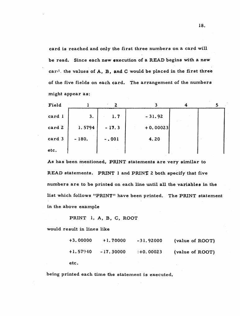
18.
card is reached and only the first three numbers on a card will
be read. Since each new execution of a READ begins with a new
carel, the values of A, B, Pond C would be placed in the first three
of the five fields on each card. The arrangement of the numbers
might appear as:
Field
card 1
card 2
card 3
etc.
1
3.
1.5794
- 180.
2
1. 7
- 11. 3
- • 001
3
- 31. 92
+ O. 00023
4.20
4
As has been mentioned, PRiNT statements are very similar to
5
READ statements. PRINT 1 and PRIN't 2 both speCify that five
numbers are to be printod on each line until all the variables in the
list which follows "PRINT" have been printed. The PRINT statement
in the above· example
PRINT 1, A, B, C, ROOT
would result in lines like
+3.00000
+1.579'10
etc.
+ 1. 70000
-17.30000
-31. 92000
:-+0.00023
being printed each time the statement is executed~
(value of ROOT)
(value of ROOT)

19.
The only difference between the two standard FORMAT sfat~ments
is that FORMAT 1 calls for fixed point input or output whereas
FORMA T 2 calls for floating point input or output.
If fixed point input is desired, data should be arranged in
five columns. Each line will be punched (by the computing center
usually) on a single card. Each number may have a sign, (un
signed numbers are interpreted as positive) and must have a
decimal point. A maximum of ten digits per number is permitted.
Several examples follow.
Statement
READ 1, A, B, C, D, E, F
Data Sheet
Case 1 A, B, C I D, E
F
Case 2 A, B, C, D, E
F
etc.
1.0
14.2
4.7
-3.0
+50001.
-1763.
-.0007
+.0589
Statements (appearing together in a program)
READ 1, A, B, C
READ 1, D, E, F, G
160. - O. 0615
87. -0.0023

20.
Data Sheet (for both READ statements)
Case 1 A, B, C 150579. 1 10000000. 15. 1007
D, E. F, G -1005.7 -.00000005 +1.0003 14.
Case 2 A. B, C 2704~3 100000. 23.0823
D. E. F. G -99.5 -.087654 +0.3879 7.
The data sheet for floating point input should be arranged with five
major columns, each column having a right-hand subcolumn wide
enough for the exponent (a sign and two digits).... The' same examples
could be written for floating point input as follows:
Statement
READ 2, A, B, C~ D, E. F
Data Sheet j
Case 1 A,B,C.D,E 1.0 '+00 +50001. '+00 -.0007.+00 1. 61+02 -6. 15~ I I , , 1
F 1
I 1.42,+01 , , I
, I
':'2.3e1 Case. 2 A,B,C,D.E 4.7 ,+00 -17630. -01 +.0589:+00 . 8.7:+01 , ·F
, -3.00.+00 ,
Statements
READ 2, A, B, C
READ 2, D,E. F, G

. 21.
Data S~eet
D,E,F,G
1.5057911 +05 1. '+07 15. 1007 :+00 : 1 I 1 1 I I 1 I
I 1-08 +1. 00031+00 1 1 .. 1. 0057 ,+03 5.0 1.4. 1 +01 I 1 , I I 1 I
2.7043: +03 :+05 I
I I 1. 23.08231+00 1
I , 1 I , I , 1
-9.95 1+01 -8. 7654: -02 +3.879 '-01 7. ,
+00 ,
I I , I
Case 1 A, B, C
Case ~ A, B, C
D,E,F,G
It is necessary that there always be three characters in the exponent
field - a sign and two digits. The limit of ten digits per· column
leaves eight digits for the number ·(inaddition !o the two required
for the exponent) •.
For fixed point output, 'PRINT l'causes numbers to be printed
with five decimal places. Five numbers ar~ printed per line. It
. should not be used if any result will exceed 999,999. If th~ input
data of the preceding examples were to be printed in fixed point,
the FORTRAN statements and printed sheets would appear as
follows.
Statement
PRINT 1, A, B, C, D, E, F
Printed Sheet
+1.00000 +50001.00000 -0.00070 +160.00000 -0.06150
+14.20000 .. '. I ••
+4.70000 -1763.00000 +0.05890 +87.00000 -0.00230
-3.00000

Statements
PRINT 1, A, B, C
PRINT 1, D, E, F, G
Printed Sheet
+ 150579.10000
-1005.70000
+Z704.30000
-99.50000
(too large to print)
+0.00000
+100000.00000
-0.08765
+15. 10070
+1. 00030
+Z3.08Z30
+0.38790
ZZ.
+14.00000
+7.00000
The use of "PRINT Z" causes numbers to be pri~ted in floating
point form, five numbers to a line. The numbers appear with
the ~ign and one digit to the left of the decimal point and five
digits to the right of the decimal point, with the. letter "E"
and the sign and the two digits of the exponent immediately
following. The FORTRAN statements necessary to print the
numbers from the preceding examples in floating point form
appear below along with examples of the printed sheets.
Statement
PRINT 2~A. B. C. D, E, F
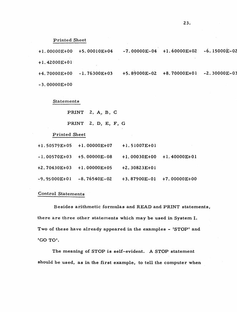
Printed Sheet
+1.OOOOOE+OO +S.OOOIOE+04
+1. 42000E+OI
+4.70000E+OO -1.76300E+03
-3.00000E+OO
Statements
23.
-7.00000E-04 +1.60000E+02 -6.IS000t-02
+S.89000E-02 +8.70000E+OI -2.30000E-03
PRINT 2, A., B, C
PRINT 2, D, E, F, G
Printed Sheet
+1.SOS79E+OS +1.OOOOOE+07
-1.OOS70E+03 +S.OOOOOE-08
+2.70430E+03 +1.OOOOOE+OS
-9.9S000E+OI -8. 76540E-02
Control Statements
+1. SI007E+OI
+1. 00030E+OO +1. 40000E+OI
+2.30823E+OI
+3. 87900E-OI +7.00000E+OO
Besides ai-ithmetic formulas and READ and PRINT statements,
there are three other statements which may be used in System 1.
Two of these have already appeared in the examples - 'STOP' and
'GO TO'.
The meaning of STOP is self-evident. A STOP statement
should be used, as in the first example, to tell the computer when
24.
th:¢ end of the calculation has been reached. It may be bmitted in
certain cases, such as that encountered in the second example,
where the absence of Cd rds in the card reader causes an automatic
halt.
The meaning and use of a GO TO statement is also quite
obvious. At any point in a program, if it is desired to specify
that the next statement to be executed is not, as is .normally the
case, the one following but instead, the statement numbered "nll,·
the statement 'GO TO n' will transfer control to that statement
and execution will proceed from there.
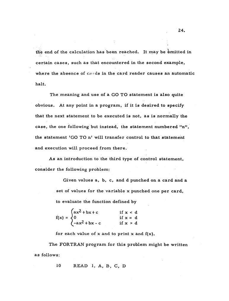
As an introduction to the third type of control statement,
consider the following problem:
Given values a, b, c, and d punched on a card and a
set of values for the variable x punched one per card,
to evaluate the function defined by
fax2 +bx+ c f(x) = 0
-ax2 +bx - c
ifx..::d if x = d ifx>d
for each value of x and to print x and f(x).
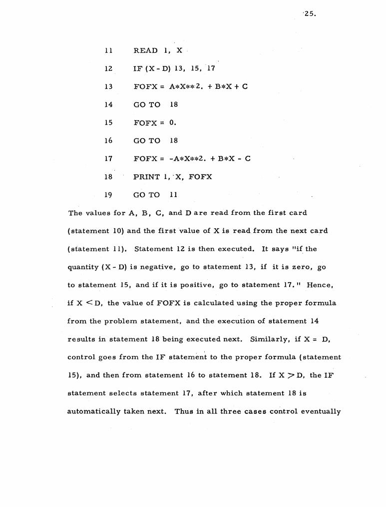
The FORTRAN program for this problem might be written
as follows:
10 READ 1, A, B, C, D
'25.
11 READ 1, X
12 IF (X - D) 13, 15, 17
13 FOFX= A*X**2. + B*X + C
14 GO TO 18
15 FOFX = O.
16 GO TO 18
17 FOFX= -A*X**2. + B*X - C
18 PRINT 1, 'X, FOFX
19 GO TO 11
The values for A, B. C, and D are read from the first card
(statement 10) and the first value of X is read from the next card
(statement 11). Statement 12 is then executed. It says "if the
quantity (X - D) is negative, go to statement 13, if it is zero, go
to statement 15, and if it is positive, go to statement 17." Hence,
if X < D, the value of FOFX is calculated using the proper formula
from the problem statement, and the execution of statement 14
results in statement 18 being executed next. Similarly. if X = D.
I
control goes from the IF statement to the proper formula (statement
15). and then from statement 16 to statement 18. If X ;:> D, the IF
statement selects statement 17, after which statement 18 is
automatically taken next. Thus in all three cases control eventually
26.
reaches the PRINT statement, which prints the value of X and
FOFX. Statement 19 then returns control to the READ statement
which reads in the next value of X, and the whole pattern repeat,s
until all of the X-cards have been proc~ssed. At this point, the
704 will automatically halt when it attempts to execute the READ
and finds no more cards in the card reader.
As has been illustrated, the 'IF' statement is really a kind
of conditional, three way,_ 'GO TO' statement. It often happens,
as in the above problem, that the computer must choose one of
two or three paths depending on whether the current value of an
expression is negative, positive, or zero. This is done by writing
IF (E) nl' n 2 ,' n3
where (E) is the expression and nl is the number of the statement
to which control is transferred if (E) is negative, n 2 if zero, and
n3 if positive.
It has been implied in this discussion that the FORTRAN
statements which make up the program are numbered. However,
it is not necessary to number every statement. The only state
ments which must be numbered are those which are referred to
(as in 'GO TO' or 'IF' statements). Any numbers between 3 and
32,000 may be used as desired, provided two different statements

27.
are never given the same number. As has been mentioned earlier,
in System I statement numbers 1 and 2 have been reserved for two
standard I FORMAT' statements (page 16).
Checklist
In the preceding description of System I, no attempt has been
made to cover in detail all of the information which will.be necessary
or helpful in writing a program. The following list of items, to":,,
gether with what has already been presented should supply this
information.
1. 1 The basic characters which may be used in writing a
FORTRAN statement are
1. 1. 1
1. 1. 2
1. 1. 3
A, B, C, ... Z (26 alphabetic characters)
0, I, 2, ..• 9 (10 numeric characters)
+ (plus), - (minus), * (asterisk), / (slash),( (left parenthesis),
) (right parenthesis), , (comma), = (equal sign), and.
(decimal point)
1. 2 Upper and lower case alphabetic characters are indisting-
uishable on a punched card, i. e. "A" and "a" will both be .
treated as "Afl.

28.
1. 3 The digits 1 and 0 must be carefully distinguished from
the alphabetic characters I and O.
1. 4 Every constant must have a decimal point.
I.5 A variable 'Symbol can consist of six or less characters.
It must satisfy the following conditions:
1.5. 1 The first character must be alphabetic.
I. S. 2' The .first character cannot be I, J, -K, L.M. or N (which ,. are set aside to denote integer variables as discussed i~
Section iI).
1. 5. 3 Any character following the first may.be alphabetic or
numeric, but not one of the special characters.
1. 5.4 The names of all functions appearing in the list of funcU6ns
as well as these names without their final letter "F" must
. not be used as variable symbols. For example, if SINF
appears in the list of functions, then neither SINF nor SIN
can be used as a variable symbol.
1. 6 In indicating a function, the name of the function must
agree exactly with the name appearing in the list of
functions.
1. 7 The argument of a function is enclosed in parentheses.
29.
1. 8 If a function has more than one argument, the arguments
are separated by commas.
I. 9 The left side of an arithmetic formula must always be
a variable.
1. 10 Never omit the operation symbol between two quantities,
e. g. do not write "AB" for "A*B".
1. 11 Never have two operation symbols in a row, e. g. do not
1. 11. 1
write "A* -B" for "A*(-B)~I.
The only exception is the operation symbol 11,-.. *", which
is regarded as a single symbol.
1. 12 Blank spaces can be used as desired since blanks are
ignored in the translation. For example,
A = 0.1
could be written as
A = 0.1
and
GO TO 25
could be written as
GOT025
1. 13 The prescribed form for the various non-arithmetic state
ments must be followed exactly (except for the arbitrary

30.
use of blank spaces). For example, the statements
READ lA, B
IF A - B, 5, 6, 7
are incorrectly written. They should be written
READ I, A, B
IF (A-B) 5,6,7
with the punctuation marks appearing exactly as specified.
I. 14 The ~agnitude 01 every n~n-zero quantity must lie bet~een
10- 38 and 1038• By "quantity" is meant any constant or any
value assumed by a variable, or function in the course of
th.,~ calcuU!1tion.
1. 15 ~bers\o be read by means of a "READ l" statement , ,
must not exceed 10 digits.
1. 16 ,'Numbers to be read by means of a "READ 2" statement
. must not exceed 8 digits. The exponent must have two
digits and a sign.
1. 17 ,Nlitmbers to be printed by means of a "PRINT I" statement
. should not exceed 999,999.99999.
1.18 , , '
The (physically) last statement of a program should be a
STOP statement or a statement which causes a tra~sfer
31.
to some other st;.ttc~n(mt in the program (a GO TO or an
IF statement).
Further Examples
1. To find the approximate numerical solution of the or
dinary differential equation
dy/dx = xy+ 1
in the interval o ~ x ~ 1, given that
y = 0 when x = o.
A crude but sometimes effective method of solving such an equation
is as follows:
Assume that a point (xO' YO) of the solution function is
known. Then from the differential equation it is also
known that dy/dx, the rate of change of y with respect
to x, at this point is xoy 0 + 1. Hence, an increment of
A x, in x would produce an approximate change in y of
Ay = Ax(xOYO + 1)
and
y(at Xl) = y(at x+ Ax) = yo + Ax (xOYO+ 1).
After the point (x l' y 1) has been obtained, it can be used
to find (xZ' YZ) in the same way, i. e.
32 .
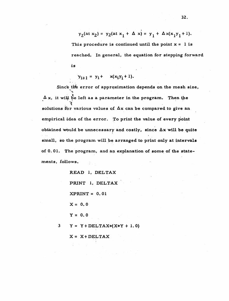
. Y2(at x2) = Y2(at xl + I:J. x) = Yl + I:J.x(xlY l + 1).
This procedure is continued until the point x = 1 is
reached. In general, the equation for stepping forward
Since tfiie error of apprqximation depends on the mesh size, '",
I:J. x, it wi¥ ~'e left as a parameter in the program. Then tlle ~.
solutionsrbr various values of I:J.x can be compared to give an
empirical idea of the error. 7'0 print the value of every point
obtained wOuld be unnecessary and costly. since I:J.x will be quite
stilall, so the program will be arranged to print only at intervals
of 0.01. The program, and an eJCPlanation of some of the state-
ments, follows.
READ I, DE.LTAX
PRINT 1, DELTAX
XPRINT = 0.01
x = 0.0
Y = 0.0
3 Y = Y + DELTAX*(X*Y + 1. 0)
x = X+DELTAX

IF (X - XPRINT) 3, 4, 4
4 PRINT 2, X, Y
XPRINT = XPRINT + O. 01
IF(X- LO) 3,5,5
5 STOP
33.
The only input to the program is the value of DELTAXpunched
in fixed point on a card, which is read by the first statement and
printed to head the answer sheet by the second statement.. The
third statement initializes the "next value to be printed" (1. e.
XPRINT) to 0.01, and the next two statements to assign the proper
initial values to X and Y. Statement 3 is the basic equation for
finding the next value of Y. Notice that the previous value of Y is
used in the calculation, and then is replaced by the result of the
calculation to give the neW value of Y. The next statement cal
culates the new value of X. This value of X is then compared with
the value of XPRlNT and if it is less than this value control goes
back to calculate the next point. As soon as X equals or, exceeds
XPRINT, the calculation is interrupted to allow the current values
of X and Y to be printed ac(:ording to statement 4 (in floating point
form). The value of XPRlNT is increased by 0.01 for the next

34.
value to be printed. Then a test is made to determine whether
the value of X has reached 1. O. If X equals or exceeds 1. 0, the
problem is finished and the computer stops (statement 5); if not,
control returns to statement 3 to calculate the next point. (Note:
the time required by the computer to calculate a point is about 0.9
milliseconds. Hence, for the case Ilx = 10- 5 , i. e. 100,000
points. the calculation time would be about 1. 5 minute s. )
2. To determine the current in an alternating current
circuit consisting of a resistance, an inductance, and a capacitance,
havin:.g been given a number of sets of values of resistance, in-
ductanee, and frequency. Th,e current is to be determined for a . ,
\ n~mber of equally spaced values of the capacitance (which lie be-
tw~en specified limits) for voltages of 1. 0, 1. 5, 2.0, 2. 5, and 3.0 \ \\
vol\ts.
The equation for determining the current flowing through
such a circuit is
i = E
~~""\»4IW'I4_'''-~'''''_." __
VR2+1(2lTfL-. 1 )2 2 lTfC
where i:: current, amperes
E = voltage, volts
R = resistance, ohms
L = inductance, henrys

35.
C = capacitance, farads
f = frequency, cycles per second
1T= 3.1416
The FORTRAN program could be written as follows:
10 READ 1, OHM, FREQ, HENRY
11 READ 2, FRD 1, FRDFIN
12 PRINT 1, OHM, FREQ, HENRY
13 VOLT = 1. 0
14 PRINT 1, VOLT
15 FARAD = FRD 1
16 AMP = VOLT/SQRTF(OHM**2. +(6. 2832*FREQ*HENRY
-1. /(6. 2832*FREQ*FARAD»**2.)
17 PRINT 2, FARAD, AMP
18 IF ( FARAD - FRDFIN) 19, 2 I, 2 1
19 ' FARAD = FARAD+O. 000 000 01
.. :0 GO TO 16
21 IF (VOLT - 3.0) 22, 10, 10
22 VOLT = VOLT+0.5
23 GO TO 14

36.
Statement 10 causes the values of the resistance, the fre-
quency, and the inductance to be read, in that order, from the
first card. Statement 11 causes He initial and final values of the
capacitance to be read from the next ca,rd. The values of the
resistance, frequency, and inductance are printed (statement 12)
in fixed point form. The initial value of the voltage is introduced
and printed (statements 13 and 14). Statement 15 causes the initial
value of the capacitance to replace the "current" value of the
capacitance (denoted as FARAD). The actual calculation is
specified by statement 16. The result of that calculation, together
with the current value of the capacitance, is printed (statement 17).'
The current value of the capacitance is compared with the
. final value to determine whether or not all values have been in-
vestigated (statement 18). If not, the expression is negative and
the program proceeds to statement 19, which causes the value of
the capacitance to be increased by the given increment. This is
followed by a transfer (statement 20) to statement 16 which causes
the calculation to be repeated for the new value of the capacitance.
If the expression in statement 18 is zero or positive, all values of
the capacitance have been investigated and the program transfers
to statement 21.
At this point the value of the voltage is compared with the

37.
upper bound to determine whether or not all specified values of the
voltage have been used. If not, the expression in statement 21 is
negative and the program proceeds to statement 22 which causes:
the value of the voltage to be increased.' Following this, a transfer
. (statement 23) is made to statement 14, which causes the new
value of the voltage to be printed and the entire process of in
vestigating all values of the capacitance is begun again •. If all
values of the voltage have been used (the expression in statement
21 is zero or positive), the calculations for the current set of
values of resistance, frequency, and inductance are finished.
The program is returned to statement 10 so that the two cards
defining the next case may be read and the program repeated.
This process is repeated until all of the cases have been con
sidered, 1. e.all of the cards have been read.