forward kinematic problem
TRANSCRIPT

Mechanism and Machine Theory 46 (2011) 945–959
Contents lists available at ScienceDirect
Mechanism and Machine Theory
j ourna l homepage: www.e lsev ie r.com/ locate /mechmt
Forward kinematic problem of 5-RPUR parallel mechanisms (3T2R) withidentical limb structures
Mehdi Tale Masouleh a,⁎, Clément Gosselin a, Manfred Husty b, Dominic R. Walter b
a Laboratoire de robotique, Département de génie mécanique, Université Laval, Québec, QC, Canada, G1V 0A6b University Innsbruck, Institute for Basic Sciences in engineering, Unit Geometry and CAD, Technikerstraße 13, A-6020 Innsbruck, Austria
a r t i c l e i n f o
⁎ Corresponding author at: Université Laval, Laborat0A6. Tel.: +1 418 656 3474; fax: +1 418 656 7415.
E-mail address: [email protected]
0094-114X/$ – see front matter © 2011 Elsevier Ltd.doi:10.1016/j.mechmachtheory.2011.02.005
a b s t r a c t
Article history:Received 21 May 2010Received in revised form 16 February 2011Accepted 17 February 2011Available online 13 March 2011
This paper investigates the formulation of the forward kinematic problem of the 5-DOF parallelmechanisms performing three translation and two independent rotations with identical limbstructures. The mathematical framework used in this paper is based on algebraic geometrywhere the forward kinematic problem is explored in a seven-dimensional kinematic space bythe means of the so-called Study parameters. In this paper, the algorithms proposed forobtaining the forward kinematic expression is based on two approaches which differ by theirconcept of eliminating passive variables. The first one is based on the application of the so-calledresultant method and the second one, as a novel approach referred to as linear implicitizationalgorithm, uses an elimination procedure based on solving several systems of linear equations.The forward kinematic problem is solved using the homotopy continuation and it is revealedthat it has 1680 finite solutions. Moreover, the forward kinematic problem is studied in three-dimensional Euclidean space where a class of simplified designs are proposed which admit asimpler formulation for the forward kinematic problem. Finally, based on the simplified designs,for a nearly general design a univariate expression of degree 220 is obtained.
© 2011 Elsevier Ltd. All rights reserved.
Keywords:5-DOF parallel mechanismsThree translations and two rotations motionpattern (3T2R)Forward kinematic problem (FKP)Study parametersElimination methodLinear implicitization algorithm
1. Introduction
The kinematic analysis of parallel mechanisms requires a suitable mathematical framework in order to describe bothtranslation and rotation in a most general way. This can be achieved by resorting to algebraic geometry. Algebraic geometry is thestudy of objects defined by polynomial equations, using algebraic means [1]. The origin of algebraic geometry is attributed toDescartes who had two brilliant ideas: (1) using coordinates to describe points in Euclidean space and (2) describing curves andsurfaces by algebraic equations. Recently, the advent of computer algebra systemsmade it possible to implement many theories ofalgebraic geometry using the algorithmic approaches [2,3]. Our interest toward applying algebraic geometry to the kinematicanalysis is mainly due to two reasons:
1. Using the superabundance of variables which eliminates the need to resort to trigonometric expressions and produceshomogeneous equations;
2. Algebraic geometry leads more naturally to a global understanding of all the solutions of a system of equations, as opposed tofinding only some of the solutions.
In this paper, the main concern is with obtaining the Forward Kinematic Expression (FKE) which is the mathematicalexpression that pertains to finding the rigid-body pose(s) that a given limb, which is referred to as the principal limb, can reach fora given actuator coordinate. As dealing with parallel mechanisms having identical limb structures, in this paper, we first focus our
oire de robotique, Département de génie mécanique, 1065 Avenue de la médecine, Québec, QC, Canada, G1V
(M. Tale Masouleh).
All rights reserved.

946 M. Tale Masouleh et al. / Mechanism and Machine Theory 46 (2011) 945–959
attention to the kinematic modelling of one kinematic chain. As mentioned previously, this kinematic chain is referred to as theprincipal limb and the fixed andmobile frame are attached respectively to the first and last joints of this chain with the direction ofthe frames based on the Denavit–Hartenberg (D–H) convention [4]. More precisely, we are taking a step back from the ForwardKinematic Problem (FKP) which pertains to finding the rigid-body pose(s) that the platform can reach for a given set of actuatorlengths. The general approach toward obtaining a univariate expression for the FKE which should be free of passive variables, i.e.,non-actuated joint-coordinates, is based on elimination theory, and the use of techniques such as the resultant [5,6] and Gröbnerbases [7–9]. It should be noted that the FKP is solved in polynomial form when one has an effective and reliable method forcomputing solutions, e.g. an algorithm to reduce the set of polynomials to a univariate.
In this paper, two approaches are proposedwhich both stem from the concepts of using Study's parameters but that differ fromtheir concept of elimination. In the first approach, the elimination of passive variables is carried out by applying a direct inspectionof the obtained expressions and is based on resultantmethod. Themain problemwith this approach is that the degree of eliminatestends to explode when resultants are used or Gröbner bases cannot be computed when the input equations are complicated. Thusfor the sake of obtaining a systematic approach and to circumvent the problem of spurious roots, in this paper, a novel approach,called the Linear Implicitization Algorithm (LIA), is proposed based on the generation of linear polynomials which is accompaniedby the computation of the Gröbner basis.
In short, our interest toward introducing and applying the LIA for obtaining the FKE is twofold:
1. Other existing algorithms, based on the resultantmethod, which require inspection and intuition, do not preclude the existenceof an expression with a lower degree which can pass through the quadrics S6
2, called Study quadric, and the constraintexpression, and contains all points which can be generated by the parametric expressions generated by the principal limb, i.e.,the FKE;
2. As compared to elimination based on resultants, the approach is more systematic and does not result in extraneous expressions.
The results of this paper open an avenue to an original direction of research in the field of the FKP of parallel mechanismswhichis the development of a systematic algorithm for the symbolic computation of the resultant of polynomials. In fact, the symbolicderivation of the resultant of polynomials can be an onerous task and requires a difficult and non unifiable inspection procedurefor the elimination sequences and may tend to be unwieldy for complex expressions.
In this paper, the 5-DOF parallel mechanisms with identical limb structures performing three translations and twoindependent rotations (3T2R) are considered in order to apply the two proposed approaches, elimination in Study coordinates andLIA, to obtain the corresponding FKE.
In general, 5-DOF parallel mechanisms are a class of parallel mechanisms with reduced degrees of freedomwhich, according totheirmobility, fall into three classes: (1) three translational and two rotational freedoms (3T2R), (2) three rotational and twoplanartranslational freedoms (3R2Tp) and (3) three rotational and two spherical translational freedoms (3R2Ts) [10]. Geometrically,the 3T2R motion can be made equivalent to guiding a combination of a directed line and a point on it. Accordingly, the 3T2Rmechanisms can be used in a wide range of applications for a point-line combination including, among others, 5-axis machine tools[11,12], welding and conical spray-gun. In medical applications that require at the same time mobility, compactness and accuracyaround a functional point, 5-DOF parallel mechanisms can be regarded as a very promising solution [13].
As far as 5-DOF mechanisms with identical limb structures are concerned, researchers have mainly worked on the typesynthesis [10,14–18]. Recently, the type synthesis of 5-DOF parallel mechanisms with identical limb structures was reviewed[10,17,19] and Huang and Li [20] and Liu et al. in [21] proposed a first architecture. It is worth noticing that most existing 5-DOFparallel manipulators are built using a 5-DOF passive leg which constrains some actuated 6-DOF limbs [22,23].
To the best of the knowledge of the authors, up to now, very few kinematic studies have been conducted on 5-DOF parallelmechanisms with identical limb structures [24–30]. This is probably due to their short history. Thus, in this research, the FKP ofsymmetrical 5-DOF parallelmechanism,more precisely 5-RPUR, is addressedwhich can be regarded as one of themost challengingtopics in the kinematics of parallel mechanisms. In this notation, ineP stands for an actuated prismatic joint, R for a revolute jointand U for a universal joint.
The remainder of this paper is organized as follows. The architecture and the general kinematic properties of the 5-DOF parallelmechanism under study which originated from the type synthesis performed in[10,17] are broadly outlined. In order to lay downthe essential concept for the projective space, Study's kinematic mapping is given. The FKE of the principal limb is obtained bymeans of Study's kinematic mapping using resultant method and the so-called linear implicitization algorithm. Then the system ofequations for the FKP, obtained by the latter two approaches in terms of Study's parameters is solved via a Homotopy Continuationalgorithm. Finally, two distinct classes of simplified designs are proposed whose FKP admit a univariate solution and for a nearlygeneral design a univariate expression is found.
2. Architecture
Figs. 1 and 2 provide respectively a schematic representation of a RPUR limb and a schematic representation for a 5-DOFparallel mechanism that can be used to produce all three translational DOFs, plus two independent rotational DOFs (3T2R) of theend-effector, namely (x,y,z,ϕ,θ). In the latter notation, (x,y,z) represent the translational DOFs with respect to the fixed frame O,illustrated in Fig. 1, and (ϕ,θ) stand respectively for the orientation DOFs around axes x and y. The mapping sequence between thedesired orientation of the platform and angles ϕ andθ is the first rotation, ϕ, about the x-axis followed by the second rotation aboutthe y-axis by angle θ.

Fig. 1. Schematic representation of a RPUR limb.
947M. Tale Masouleh et al. / Mechanism and Machine Theory 46 (2011) 945–959
More generally, this mechanism consists of an end-effector which is linked by 5 identical limbs of the RPRRR type to a base. Theinput of the mechanism is provided by the five linear prismatic actuators. From the type synthesis presented in [17], the geometriccharacteristics associated with the components of each leg are as follows: The five revolute joints attached to the platform (the last Rjoint in eachof the legs) haveparallel axes, thefive revolute joints attached to thebasehaveparallel axes, thefirst two revolute joints ofeach leg have parallel axes and the last two revolute joints of each leg have parallel axes. It should be noted that the second and thirdrevolute joints in each leg are built with intersecting and perpendicular axes and are thus assimilated to U joints. This mechanicalsimplification leads toa 5-RPUR typemechanism.Asmentioned above, the 5-RPUR is a limited-DOFparallelmechanismand contains aconstrained rotational DOFwhich is in a direction parallel to e1×e2, where e1 and e2 are unit vectors respectively along the axes of thefirst (and second) and third (and fourth) revolute joints of the ith leg, as illustrated in Fig. 1. Further results regarding the kinematicproperties, such as the solution of the IKP and the determination of the constant-orientation workspace can be found in [24].
3. Two approaches for formulating the FKE in seven-dimensional kinematic space
3.1. Study's kinematic mapping
Study's kinematic mapping is a mapping of an element γ of the Euclidean displacement group SE(3) into a 7-dimensionalprojective space, P7 [31]. The homogeneous coordinate vector of a point in P7 is X=[x0 : x1 : x2 :x3 :y0 :y1 :y2 :y3] where x=[x0 : x1 : x2 :x3] and y=[y0 :y1 :y2 :y3]. The kinematic pre-image of X is the displacement α described by the transformationmatrix
where
Ω =1Δ
Δ 0 0 0
p x20 + x21−x22−x23 2 x1x2−x0x3ð Þ 2 x1x3 + x0x2ð Þq 2 x1x2 + x0x3ð Þ x20−x21 + x22−x23 2 x2x3−x0x1ð Þr 2 x1x3−x0x2ð Þ 2 x2x3 + x0x1ð Þ x20−x21−x22 + x23
2666664
3777775
ð1Þ
p = 2 −x0y1 + x1y0−x2y3 + x3y2ð Þ;q = 2 −x0y2 + x1y3 + x2y0−x3y1ð Þ;r = 2 −x0y3−x1y2 + x2y1 + x3y0ð Þ;
ð2Þ
=x02+x1
2+x22+x3
2. Note that xi, i=0,…3, are the so-called Euler parameters and they have to fulfil an orthogonality
and Δcondition with the remaining four parameters yi, i=0,…3 [32]:S26 = x0y0 + x1y1 + x2y2 + x3y3 = 0; ð3Þ

2
Table 1D–H pa
123
Fig. 2. Schematic representation of a 5-RPUR parallel mechanism.
948 M. Tale Masouleh et al. / Mechanism and Machine Theory 46 (2011) 945–959
t all xi are zero. If these conditions are fulfilled [x0 :… :y3]T are called Study parameters of the displacement α. Eq. (3) defines
and noa quadric S62⊂P7 and the range of the kinematic mapping ϰ is this quadric minus the three dimensional subspace defined byE : x0 = x1 = x2 = x3 = 0: ð4Þ
lled Study quadric and E is the exceptional or absolute generator. One can normalize the parameters such that Δ=1, then the
S6 is cacoordinate x0 represents the cosine of the half rotation angle. Note that there are other possibilities to normalize, but these are notused within this paper.3.2. FKE via elimination in study coordinates
Now,we turn our attention to the kinematicmodeling of a RPUR limb. As dealingwith a parallel mechanismwith identical limbstructures, we first focus our attention to the kinematic modeling of one kinematic chain, the principal limb. Then, havingdetermined the algebraic equations for the kinematic modeling of the principal limb, the kinematic modeling of its correspondingparallel mechanism can be obtained.
Referring to Fig. 3 one can readily obtain the D–H parameters of the principal limb which are given in Table 1 where ρp and lpstand for the prismatic elongation (assumed to be known) and leg length of the secondmoving link, respectively. Applying the D–Hconvention the two following transformation matrices are obtained:
Σi =
1 0 0 00 cos ui −sin ui 00 sin ui cos ui 00 0 0 1
2664
3775 i = 1;…;4; ð5Þ
Γi =
1 0 0 0ai 1 0 00 0 cosαi −sinαidi 0 sinαi cosαi
2664
3775 i = 1;2;3; ð6Þ
rameters for a RPUR limb.
ai di αi ui
ρp 0 0 u10 0
π2
u2lp 0 0 u3

2222
z4
Bi
lp
x1
y1
x3
y2
z3
x2
x4
Ci
ρp
Ai
Fig. 3. Local system attached to each R joint for the D–H parameters.
949M. Tale Masouleh et al. / Mechanism and Machine Theory 46 (2011) 945–959
ui is the ith joint coordinate,Σi stands for the rotation about the x′i-axis of the ith R joint and Γi represents the transformation
wherebetween successive local coordinate frames. In this paper, i is a local dummy variable. Thus the FKE for the principal limb withrespect to joint variables and the design variables can be expressed as follows:F = ∏3
i=1ΣiΓi
� �Σ4: ð7Þ
Reaching this step, the so-called kinematic mapping should be applied to F=[fij]i, j=1,…, 4 which amounts to computing theStudy parameters, X, from matrix F. For that, Study in [33] presented a singularity-free procedure in which the homogeneousquadruple x can be obtained from at least one set of four proportions [31]. Here, among the four proportions the followingproportion is chosen:
x0 : x1 : x2 : x3 = 1 + f22 + f33 + f44 : f43−f34 : f24−f42 : f32−f23: ð8Þ
Then, the four remaining Study parameters y=(y0 :y1 :y2 :y3) can be computed from:
y0 = f21x1 + f31x2 + f41x3y1 = −f21x0 + f41x2−f31x3y2 = −f31x0−f41x1 + f21x3y3 = −f41x0 + f31x1−f21x2:
ð9Þ
on substituting F into Eqs. (8) and (9), and applying the tangent half-angle substitution, ti = tanui
� �, i=1,2,3,4, it turns out
Up2that all the computed Study parameters share a common factor which is:
1 + t1t2t3t4−t3t4−t2t4−t1t4−t1t2−t1t3−t2t31 + t21� �
1 + t22� �
1 + t23� �
1 + t24� � : ð10Þ
Using the fact that the above parameters are homogeneous allows to omit this common factor and one may obtain thefollowing for the rotational parameters of the Study parameters:
x0 = 2 t1t2t3t4−t1t2−t1t3−t1t4−t2t3−t2t4−t3t4 + 1ð Þ; ð11Þ
x1 = 2 t1t2t3t4−t1t2 + t1t3 + t1t4 + t2t3 + t2t4−t3t4 + 1ð Þ; ð12Þ
x2 = 2 t1t2t3 + t1t2t4−t1t3t4−t2t3t4 + t1 + t2−t3−t4ð Þ; ð13Þ
x3 = 2 −t1t2t3−t1t2t4−t1t3t4−t2t3t4 + t1 + t2 + t3 + t4ð Þ; ð14Þ
which
1 Thesummin
950 M. Tale Masouleh et al. / Mechanism and Machine Theory 46 (2011) 945–959
consequently leads to the following for y=(y0 :y1 :y2 :y3):
y0 = ρp + lp� �
−t1t2t3t4−t1t4 + t2t3 + 1ð Þ + ρp−lp� �
t1t2−t1t3 + t2t4−t3t4ð Þ; ð15Þ
y1 = ρp + lp� �
t1t2t3t4−t1t4 + t2t3−1ð Þ + ρp−lp� �
−t1t2−t1t3 + t2t4 + t3t4ð Þ; ð16Þ
y2 = ρp + lp� �
t1t2t3−t2t3t4−t1 + t4ð Þ + ρp−lp� �
t1t2t4 + t1t3t4 + t2 + t3ð Þ; ð17Þ
y3 = ρp + lp� �
t1t2t3 + t2t3t4 + t1 + t4ð Þ + ρp−lp� �
t1t2t4−t1t3t4−t2 + t3ð Þ: ð18Þ
The objective now is to combine all the above expressions, Eqs. (11–18), by eliminating passive variables, i.e., ti, i=1,…,4, inorder to obtain the FKE of the principal limb with respect to Study's parameters and design and input parameters, ρp and lp. In fact,a rigid body is fully described by six constraint equations in space. In this case, fixing the input, P joint, results in a RUR kinematicarrangement which has four DOFs. Hence the aim of the whole elimination procedure is to find two independent constraintequations for the FKE of one limb. In this paper, two well-known algorithms of elimination theory are used, namely the resultantmethod and the Gröbner base algorithm.
Before proceeding to the elimination of the passive variables, matrix F is expanded and it reveals that f44=0 which amounts toΩ44=0 which is a component of Ω, Eq. (1):
C = x20−x21−x22 + x23 = 0: ð19Þ
Thus, before any elimination, a quadric, called constraint equation, is found which is free of any design parameters and can beregarded as the first constraint equation. This result is consistent with results found for the rotational parameters, x, in Eq. (11–14)which are all free of any design parameters, i.e., li and ρi and are all expressions in joint space, ti. In otherwords,five RPUR limbs share acommon rotational constraint as confirmed by the type synthesis performed for such a mechanism in [10]: The mechanism has arotational constraint about the axis defined by e1×e2. Eq. (19) is a statement equivalent to the latter written in terms of Study'sparameters and indicates that the rotational constraint of thismechanism lies on a quadric. The existence of this quadric togetherwiththe homogeneous condition,Δ=1, and the Study quadric in P7, results in two independent rotational parameters for themechanism.
Returning now to the FKE and Eqs. (11–18), skipping mathematical details, upon applying a step by step resultant method toEqs. (11–18) and eliminating successively the passive variables t3, t2, t4 and t1, leads to three independent sixth degreepolynomials, {T1,T2,T3}, with respect to the Study and design parameters. In fact, all the points describing the variety V generatedby the principal limb lie on the these expressions, together with C and S6
2. The expressions for {T1,T2,T3} are rather long and arepresented in Appendix A. According to the dimension formula, the degree and number of obtained expressions are coherent withthe dimensions of the eliminated variables, vi, which is four. In summary, the FKE of the principal limb can be defined by thefollowing ideal1:
I = b T 1;T 2;T 3;S26;C>; ð20Þ
ree sixth degree polynomials, Ti, and two quadric S62 and C, the Study and the constraint quadric, respectively. The above
i.e., thformulation channels us to apply a Gröbner base algorithm [1], a powerful algebraic geometry algorithm, to the ideal I. From analgebraic geometry stand point, Gröbner bases can beviewed as anorganizedway to generate newpolynomials in the ideal selecting asubset that retains exactly the same solution set as the original polynomials, and determining a valid set of monomial identities thatcomplete the definition of an eigenvalue problem [34]. Upon computing the Gröbner basis of the ideal Iwith respect to themonomialorder x0≺x1≺x2≺x3≺y0≺y1≺y2≺y3, and after several mathematical manipulations, the following expression is found:
Fp Xð Þ = −8 ρ2p + l2p� �
y1x1 + y2x2ð Þ2 + 8 ρ2p−l2p� �
y1x2−y2x1ð Þ −x0y3 + y0x3ð Þ
+ 16 y22 + y21� �
y20 + y23� �
+ ρ2p−l2p� �2
x22 + x21� �2
= 0:ð21Þ
The above polynomial is of degree four, instead of six for T{i=1,2, 3}, and together with Eq. (19) and the Study quadricexpression could be regarded potentially as the simplest expression describing the FKE of a RPUR limb in terms of the Studyparameters, X. The latter issue will be confirmed formally using the LIA. Thus, reaching this step two expressions are in place,Eqs. (19) and (21), which fully constrain the mechanism in space. In order to ensure the validity of Eq. (21), the back-solving canbe applied for the Study parameters found in Eqs. (11–18) into Fp(X) and observe that Fp vanishes. It can be shown that Fp(X) isvalid for all limb kinematic arrangements of symmetrical 5-DOF parallel mechanisms performing the 3T2R motion pattern withprismatic actuators, such as PRUR for the so-called Pentapteron [25]. These kinematic arrangements are the results of type
ideal I(F) of a system of polynomials F={f1, f2,…, fn} is the set of all polynomials that can be formed by multiplying each fi by a polynomial gi andg them up: I(F)={h|h=g1f1+g2f2+…+gnfn}, where gi can be any polynomial in the same variables as F [1].

2
1
052.5
0
-2.5
-5-5 -2.5
0
2.5
5
-5
-2.5 0 2.5 5
Fig. 4. Study mapping of the vertex space of a RPUR limb, F (y), for a given orientation, (x0,x1,x2,x3)=(1,1,4,4), and design parameters ρp= lp=1.
951M. Tale Masouleh et al. / Mechanism and Machine Theory 46 (2011) 945–959
synthesis performed for symmetrical 5-DOF parallel mechanisms and a comprehensive list of them can be found in [10]. Thegeometrical meaning of Eq. (21) is difficult to assess. However, in [24], it is shown that in the three-dimensional kinematic spacethe vertex space for a given orientation and input of a RPUR limb generates a Bohemian dome. This quartic surface can be generatedby moving a circle that remains parallel to a plane along a curve that is perpendicular to the same plane. Thus for a given x;ρi; lið Þ,Fp yð Þ can be interpreted geometrically as the Study mapping of a Bohemian dome, Fig. 4. In this mapping one should take intoaccount C, for the feasible orientation, and S6
2, the Study quadric.
3.3. FKE via Linear Implicitization Algorithm (LIA)
In this section,we introduceanalternative toeliminationbasedon implicitizationwhich is called the LIA. It iswell known that thereexists a one-to-one correspondence from all spatial transformations to the Study quadric, S62, which lives in CP7. Particularly, thismeans that a tuple of Study parameters describing a transformation is a projective point and consequently always only unique up toscalarmultiples. For a givenparametrized transformation (e.g. Eqs. (11–18)) one canobtain the set of corresponding points inCP7 andsearch for the smallest variety V ∈CP7 (with respect to inclusion)which contains all these points.What is in place about this variety atthe earlier stage? Definitely, it can be confirmed that its ideal consists of homogeneous polynomials and contains S62, i.e. the equationfor the Study quadric. In the following it is shown how additional equations can be computedwhich are necessary to describe V, Eqs.(11–18). From the above analysis, the transformation depending on four parameters t1, t2, t3, t4, which is given by thematrix F, Eq. (7),is in hand. The parameters come from the tan-half-angle substitution which was made to get rid of the trigonometric functions. Thismethod leads in general to four different 8-tuples which can be used to represent the Study parameters. Fortunately they are notessentially different, they are all multiples of one special 8-tuple. Using Study's method to compute the Study parameters out of theentries of a Euclidean displacement matrix Eqs. (8) and (9), one can obtain four seemingly different 8-tuples.
The next step consists in searching for homogeneous polynomials which vanish on all points producible from thisparametrization, i.e. polynomials in [x0,x1,x2,x3,y0,y1,y2,y3] which are 0 when these expressions are substituted. One possibility tofind such necessary polynomials is the following: The ansatz is g c;xð Þ = ∑ j j j =n cjxj, which after the substitution becomesf c; tð Þ = ∑j∈Jαj cð Þtj, where the coefficient functions f = αj cð Þ are all linear. Due to the fact that f has to vanish for all values of theti, it has to be the zero polynomial. It follows that all coefficients of f themselves have to be 0. So after extraction of these
coefficients one obtains a system of linear equations where the unknowns are the n + 7n
� �coefficients from the general ansatz.
This system can be solved (assuming that the design parameters a1=ρp and a3= lp are generic) and the solution can besubstituted into the ansatz. The result is an expression r describing all homogeneous polynomials of degree nwhich vanish on thepoints of V. An important point is that if the solution of the linear system is positive dimensional, the corresponding parametersalso appear in the final expression, i.e. the expression r itself is parametrized. Now, we start with the smallest degrees.
n = 1 :
This case results in 16 linear equations in 8 unknowns. The solution of the system is the zero vector and it follows that r=0, i.e.there are no homogeneous linear polynomials which vanish on V.
n = 2 :
In this case, the problem is equivalent to 81 linear equations in 36 unknowns. The solution of the system is now 2-dimensionaland for the final expression r, one has:
r = x0y0 + x1y1 + x2y2 + x3y3ð Þp1 + x20−x21−x22 + x23� �
p2: ð22Þ

952 M. Tale Masouleh et al. / Mechanism and Machine Theory 46 (2011) 945–959
pi are the parameters for the positive-dimensional solution of the linear system. The above means that all quadratic
whereexpressions vanishing on V are a linear combinations of these two polynomials, q1 and q3, and particularly that each of them alonevanishes on V. Thus the first two equations which are necessary to describe the constraint variety appear in this step.n = 3 :
For this degree we get 256 linear equations in 120 unknowns. After solving the system we get a 16-dimensional solutionand:
r = ∑16
i=1cipi; ð23Þ
the ci are again polynomials in the Study parameters. Most of them look like e.g. y3(x0y0+x1y1+x2y2+x3y3), i.e. they do
wherenot introduce new information. To find out which of these 16 polynomials lead to something new, all are reduced with a Gröbnerbasis computed from the equations from the previous case. The result is that all are reduced to 0, i.e. all cubic polynomialsvanishing in V can be generated from the known quadratic ones.n = 4 :
Once again the same procedurewith 625 linear equations in 330 unknowns. After solving the system yields to a 72-dimensionalsolution:
r = ∑72
i=1cipi; ð24Þ
lynomials in the Study parameters as the coefficients ci. After reduction of themwith the two quadrics, q1 and q2, using the
and poGröbner basis from above exactly one non-zero polynomial remains. This means that we get here a new polynomial, q3, which isnot a combination of the known ones. Until now we have the following describing equations for the variety V:q1 = x0y0 + x1y1 + x2y2 + x3y3≡S26; ð25Þ
q2 = x20−x21−x22 + x23≡C ; ð26Þ
q3 = −8 ρ2p + l2p� �
y1x1 + y2x2ð Þ2 + 8 ρ2p−l2p� �
y1x2−y2x1ð Þ −x0y3 + y0x3ð Þ
+ 16 y22 + y21� �
y20 + y23� �
+ ρ2p−l2p� �2
x22 + x21� �2≡Fp:
ð27Þ
Due to the fact that we had four parameters ti and the fact that the dimension of the variety generated by these equations isnow also 4, we stop the process here and use equations q1,q2,q3 as the describing equations of the constraint variety.
4. Solving the general FKP expressed in seven-dimensional kinematic space
The first step is to obtain the system of equations representing the FKP, i.e., the FKE corresponding to four other limbs, j=2,…,5. Thus a transformation in the Study parameters X should bemade in both base andmoving frame and can be done by followingthe procedure described in [31]. Consider bj = b0j : … : b7j
� �andmj = m0j : … : m7j
� �as the Study parameters describing the jth
limb placement in the base (fixed frame) and in the moving platform (mobile frame), respectively. Since the axes of the R jointsfixed to the base, e1, are all parallel thus bj consists of a pure translation. This has the following consequences for the Studyparameters of this transformation:
b0j = b1j = b2j = b3j = b4j = 0: ð28Þ
The same issue follows for axes of the R joints attached to the platform, e2, and leads to:
m0j = m1j = m2j = m3j = m4j = 0: ð29Þ
These particularities for the axes attached to the base and platform should not be interpreted as mechanical simplifications andis originating from the type synthesis preformed for such mechanisms. Thus based on the transformation matrices presented in[31], one may obtain:
jTb = I4×4 04×4Bj I4×4
� ;
jTm = I4ñ4 04×4Mj I4×4
� ; ð30Þ

so tha
which
953M. Tale Masouleh et al. / Mechanism and Machine Theory 46 (2011) 945–959
t B j and M j are the following skew-symmetric matrices:
Bj =
0 −b5j −b6j −b7jb5j 0 −b7j b6jb6j b7j 0 −b5jb7j −b6j b5j 0
2664
3775; Mj =
0 −m5j −m6j −m7jm5j 0 m7j −m6jm6j −m7j 0 m5jm7j m6j −m5j 0
2664
3775:
ð31Þ
Thus the transformation becomes:
Xj =jTm
jTb
� �−1X; ð32Þ
once expanded leads to:
Xj =
xT
b5j + m5j
� �x1 + b6j + m6j
� �x2 + b7j + m7j
� �x3 + y0
−b5j−m5j
� �x0 + b7j−m7j
� �x2 + −b6j + m6j
� �x3 + y1
−b6j−m6j
� �x0 + −b7j + m7j
� �x1 + b5j−m5j
� �x3 + y2
−b7j−m7j
� �x0 + b6j−m6j
� �x1 + −b5j + m5j
� �x2 + y3
2666666664
3777777775: ð33Þ
Thus the FKE of the jth limb, Fj, can be found as follows:
F j = Fp X↦Xj;p↦j� �
: ð34Þ
From Eq. (33) it follows that the Study rotational parameters, (x0 :x1 :x2 :x3), remain the same for all limbs. In summary, the FKPfor the mechanism is equivalent to 8 equations and 8 unknowns:
G =
F p = 0
F j = 0 j = 2;…;5
S26 = 0
C = 0
Δ = 1
8>>>>>>>><>>>>>>>>:
ð35Þ
For the FKP, the above system of equations should be solved for Xwith design values of: bj;mj; lj; ρj �
. Although the degree ofeach of the FKE is reduced from 6 to 4, Ti, i=1,2,3, versus Fp, the contribution to the total degree of the system is reduced evenmore dramatically, fro 63 to 41. However, the degree is still too high to apply the resultantmethod toG in order to find a univariateexpression for the FKP. This channels us to use numerical algebraic geometry which can be regarded as the intersection ofalgebraic geometry and numerical analysis. A number of numerical algebraic algorithms have been implemented in Bertini[34,35]. Bertini is a software for solving polynomial systems using the Homotopy Continuation approach. Using Bertini, it followsthat the FKP of a general 5-RPUR admits 1680 finite solutions, real and complex. Numerous random examples in solving the set ofEqs. (35) reveal that the FKP of this 5-DOF parallel mechanism may admit up to 208 real solutions among the 1680 finitesolutions. However, this is not necessarily the upper bound for the number of real solutions because this result was obtainedthrough simple numerical trials. Providing an upper bound for the number of real solutions requires the development of aunivariate expression for the FKP which is an extremely complicated task. Obtaining 1680 finite solutions and also 208 realsolutions leads to conclude that arriving at a univariate expression for the FKP of this parallel mechanism should be extremelydifficult especially considering the complexity of deriving a univariate expression for the forty solutions of the FKP of the Gough–Stewart platform [36].
In order to ensure the validity of the solutions obtained by Bertini all the real solutions are back substituted into the IKPexpression found in [24] which is expressed in terms of the three-dimensional kinematic space. This test reveals that for allsolutions converted to Cartesian coordinates and Euler angles the same set of prismatic actuator elongations can be found. Thetransformation of Study parameters into Cartesian coordinates and Euler angles is elaborated in [37].
954 M. Tale Masouleh et al. / Mechanism and Machine Theory 46 (2011) 945–959
Applying the so-calledwitness set method, Bertini has the ability to detect positive dimensional solution sets. Using this featureof Bertini, it can be confirmed that regardless of the inputs and geometric parameters of the mechanism, the following complexsets are always a solution of Eq. (35):
2 The
x0 = 0 x3 = 0 x1 = −ix2 y1 = −iy2x0 = 0 x3 = 0 x1 = ix2 y1 = iy2x1 = 0 x2 = 0 x0 = −ix3 y0 = −iy3x1 = 0 x2 = 0 x0 = ix3 y0 = iy3:
ð36Þ
As the equations are linear, the dimension formula shows directly that each of the lines in Eq. (36) represents a three-dimensional complex space. The above solutions lie in these four three-dimensional spaces and the solution set itself is then theintersection of this three-dimensional linear space with the Study quadric. Because this set is always complex, it can nevercontribute to the real solutions of the FKP regardless of the chosen design parameters. However, algebraically the above set ofsolutions are a valid solution for the FKP.
In summary, using the Study kinematicmapping, the FKP of the general 5-RPURmechanism is reduced to a system of equationsG of degree 4 whose compactness and simplicity make it suitable to use Bertini. It should be noted that due to the fact that Fp is ofdegree 4 then this system of equations, on the basis of Bezout's theorem2 [38,39], has an upper bound for the number of solutions of45×2×2=4096 (four times Fp, C, S 2
6, and Δ=1) while using Ti={1, 2, 3}, instead of Fp, leads to 65×2×2=31,104. This upperbound corresponds to the number of paths to be tracked by the homotopy continuation in Bertini and a reduction of this numberdecreases the computation time for Bertini.
5. FKP in three-dimensional Euclidean space
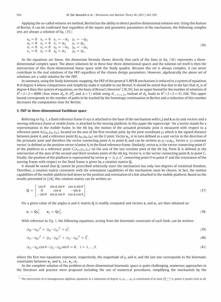
Referring to Fig. 1, a fixed reference frame O-xyz is attached to the base of themechanismwith i, j and k as its unit vectors and amoving reference frame ormobile frame, is attached to the moving platform. In this paper the superscript ′ for a vector stands for arepresentation in the mobile frame. In the ith leg, the motion of the actuated prismatic joint is measured with respect to areference point Ai(xAi,yAi,zAi), located on the axis of the first revolute joint, by the joint coordinate ρi which is the signed distancebetween point Ai and a reference point Bi(xBi,yBi,zBi) on the U joint. Vector eρi is in turn defined as a unit vector in the direction ofthe prismatic joint and therefore the vector connecting point Ai to point Bi and can be written as ρi=ρieρi. Vector ri (a constantvector) is defined as the position vector of point Ai in the fixed reference frame. Similarly, vector si is the vector connecting point O′of the platform to a reference point Ci(xCi,yCi,zCi) on the axis of the last revolute joint of the ith leg. Point Bi is defined as theintersection of the axes of the second and third revolute joints of the ith leg. Vector vi is the vector connecting point Bi to point Ci.Finally, the position of the platform is represented by vector p = x; y; z½ �T connecting point O to point O′ and the orientation of themoving frame with respect to the fixed frame is given by a rotation matrix Q .
It should be noted that Q cannot be prescribed arbitrarily since the mechanism has only two degrees of rotational freedom.Therefore, a rotation matrix consistent with the orientation capabilities of the mechanism must be chosen. In fact, the motioncapabilities of themobile platform boil down to the position and orientation of a line attached to themobile platform. Based on theresults presented in [24], this rotation matrix can be written as:
Q =cos θ sinϕ sin θ cosϕ sin θ0 cosϕ −sinϕ
−sin θ sinϕ cos θ cosϕ cos θ
24
35: ð37Þ
For a given value of the angles ϕ and θ, matrix Q is readily computed and vectors si and e2 are then obtained as:
si = Qs0i; e2 = Qe
02: ð38Þ
With reference to Fig. 1, the following equations, arising from the kinematic constraint of each limb, can be written:
xBi−xAið Þ2 + zBi−zAið Þ2 = ρ2i ; ð39Þ
xCi−xBið Þ2 + yCi−yBið Þ2 + zCi−zBið Þ2 = l2i ; ð40Þ
xCi−xBið Þcos θ− zCi−zBið Þsin θ = 0; i = 1;…;5; ð41Þ
the first two equations represent, respectively, the magnitude of ρi and vi and the last one corresponds to the kinematic
whereconstraints between e2 and vi, i.e., e2⊥vi.As the complete solution of the problem in three-dimensional kinematic space is quite challenging, numerous approaches inthe literature and practice were proposed including the use of numerical procedures, simplifying the mechanism by the
intersection of m homogeneous algebraic equations in n unknowns of degree n1,n2,…,nm is constituted of at most ∏i = mi = 1 ni points it points exist at all.

x
vi j e2
z
ρ jρ i
Bi j
Ci j
A jAi
(a) 1
z
x
e2
e2
Ai j
Ci
Cj
B jBi
v j
e2vi
(b) 2
x
z
Bi
Ai A j
e2
CjCi
B j
v jvi
(c) 3
Fig. 5. Simplified kinematic arrangements.
955M. Tale Masouleh et al. / Mechanism and Machine Theory 46 (2011) 945–959
coalescence of some of the connection points on the platform or the base and, finally, to use some extra sensors. Similarly, in thisproject, simplifying the mechanism by the coalescence of some of the connection-points is considered for solving the FKP with theaim of obtaining a simpler design, reducing the mechanical interferences and increasing the workspace volume.
From the results obtained in [24], for the IKP and the FKP for a particular case, one could extend the latter study, for the FKPresolution, to the following conclusion: Any mechanical simplifications that provides the coordinate of two pairs of U jointsexplicitly or a relation between them leads to a univariate expression for the FKP.
The foregoing issue remains central to the development of the simplified designs having a closed-form solution for the FKP.Having the above conclusion in mind, consider two limbs, i and j, for which:
1. The connection points at the base, Ai and Aj, are in a plane with e1 as normal or coincide;2. Both second moving links have the same leg length, li= lj, or coincide;3. The connection points at the platform, Ci and Cj, are aligned with e2, or coincide.
From the IKP presented in [24], it follows that the design conditions result in a simplified arrangement in which both secondmoving links are parallel, vi∥vj, or coincided, and the line connecting Bi to Bj is aligned with e2, or again coincided. Consequently, insuch a design there is a pair of U joints having a relation between them, i.e., the line connecting them is aligned with e2 whichimplies that:
xBj−xBi = sj−si� �
cos θ; ð42Þ
zBj−zBi = si−sj� �
sin θ; ð43Þ
si is a geometric parameter of the platform representing the component of s i along x, the vector connecting the limb to the
wheremobile frame, i.e., Ci to O′. Therefore, in a design for which two pairs of limbs fulfill the above three conditions, on the basis of theabove conclusion, then the FKP admits a closed-form solution. There are three distinct situations, S={A 1,A 2A 3}, in which theabove three conditions can occur and they are depicted in Fig. 5. Therefore, all second order subsets of S adopt a univariateexpression for their FKP:A 1A1f g; A 1A2f g; A 1A3f g; A 2A3f g; A 2A2f g; A 3A3f gf g: ð44Þ
For instance, {A 1A 2} is a 5-DOF parallel mechanism which consists of two combined arrangements A 1 and A 2 plus a regularlimb of the RPUR type. Fig. 6 shows a CAD model of a A 1A 1 parallel mechanism. As it can be observed, the U joints in A 1
arrangements are designed in such a way that there is an offset between the axes, which leads to a reduction in the mechanicalinterferences and hence a large travel for the joints. In such a situation, although the joint is no longer a U joint per se, thekinematic model given above remains valid. From Eq. (44) it follows that {A 3A 3}, Fig. 2, is free of any coalescence of connectionpoints and comparing with other designs presented above could be regarded as the most general design having a closed-formsolution for the FKP. The FKP of the designs belonging to Eq. (44) are treated in [29,30,40]. In the following section the FKP of adesign containing one arrangement of type A i is investigated.

with:
i = 1i = 3 i = 4
i = 5
y
i = 2
zx
Fig. 6. Schematic representation of a {A 1A 1} parallel mechanism.
956 M. Tale Masouleh et al. / Mechanism and Machine Theory 46 (2011) 945–959
5.1. FKP for a design containing one arrangement of type A i
In such a design only one simplified arrangement belonging to S is considered. No matter which one is chosen the approachtoward obtaining a univariate expression for the FKP remains similar. Let us consider A 1 in order to describe the approach andFig. 7 depicts, notationally, such a design. As it can be observed from the latter figure, the fixed frame is attached to O(x, y, x)≡B12,whose coordinates are known for the FKP, and the direction of the principal axes are such that the x′-axis is in the direction of e2,the y-axis remains in the direction of e1 and obviously the z-axis becomes in the direction of e1 × e2. The origin of the mobileframe coincides with C12. For this case, the constraint equations, Eqs. (39–41), are re-formulated with respect to the new frames.The constraint equations for A 1 can be expressed as:
F1 = y2 + z2−l212 = 0; ð45Þ
xB12 = zB12 = x = 0: ð46Þ
For the three regular limbs, i=3,4,5, which are free of mechanical simplifications, one has:
yCi−yBið Þ2 + zCi−zBið Þ2−l2i = 0; ð47ÞxBi−xAið Þ2− zBi−zAið Þ2−ρ2i = 0; ð48Þ
xCi−xBi = 0: ð49Þ
The coordinates of the passive variables Ci can be computed as follows:
xCi; yCi; zCi½ �T = p + Qϕs′i; ð50Þ
Qϕ =1 0 00 cosϕ −sinϕ0 sinϕ cosϕ
24
35: ð51Þ
Due to special considerations for thefixed frame, i.e.,O≡B12, the coordinates of thefixed R joint,Ai, for the three regular limbs areno longer knownparameters and depend on the orientation of the fixed frame around the y-axis, namely θ. This implies that:
xAi; yAi; zAi½ �T = QTθ rBi ; i = 3;4;5; ð52Þ

where
Fig. 7. Schematic representation for a design containing one arrangement of type A 1.
957M. Tale Masouleh et al. / Mechanism and Machine Theory 46 (2011) 945–959
Qθ =cos θ 0 sin θ0 1 0
−sin θ 0 cos θ
24
35: ð53Þ
In the above, rBi stands for the vector connecting B12 to Ai expressed in a frame similar to the one used in Fig. 1 but originatingfrom B12.
The first step is to find the FKE of each limb. For the arrangement A 1 the FKE is already known, Eq. (45). Moreover, fromEq. (46) it follows that x=0. Thus, one unknown for the FKP is readily in place. For the sake of obtaining the simplest expressiondescribing the FKE of the three others limbs, i=3,4,5, one should subtract Eq. (45) from Eq. (47). Then, taking the resultant of thelatter expressionwith Eq. (48), by substituting Eq. (49), with respect of zBi yields a second degree expression, called Fi, i=3,4,5, for
y and z. This expression is of degree 4 in degree with respect to t = tanθ2
� �and u = tan
ϕ2
� �and as a whole the final expression is
of degree 10. Although it seems that the degree of the expressions is too high to proceed to the resultantmethod, upon consideringan appropriate sequence of elimination together with some simplifications and factoring in each step of elimination it is possible toobtain a univariate expression for t, namely Ft:
F34 = Res F3; F4;uð Þ = 0;F45 = Res F4; F5;uð Þ = 0;F341 = Res F34; F1; yð Þ = 0;F451 = Res F45; F1; yð Þ = 0;Ft = Res F451; F341; zð Þ = 0:
ð54Þ
In the above, Res(a,b,c) stands for the resultant of polynomials a and b with respect to the common variable c. Thus, Ft is theunivariate expressionwith respect to twhich consists of 7 polynomial factors. Only one of these factors corresponds to the FKP andthis can be found using Bertini. To do so, the system of equations constituted by Eq. (45) and Eqs. (47–49) with respect to variables(y,z, t,u,zB3,zB4,zB5) is given to Bertini, which reveals that all solutions found by Bertini correspond to the solution of only one ofthe seven factors of Ft. This expression is of degree 220which allows us to conclude that the FKP for this design can be expressed bya univariate expression of degree 220 with respect to t. Moreover, using the FKE expressed in term of Study parameters, Eq. (21),for this nearly general design results in 1680 finite solutions which appears to be inconsistent with the univariate expression ofdegree 220. This inconsistent number of solutions is due to the fact that Eq. (21) does not take into account the fact that there is aA 1 arrangement, i.e., a coalescence for two U joints in B12. Thus all the 1680 solutions, complex and real, should be verified in sucha way that the two limbs belonging to the A 1 arrangement, here i=1,2, have the same working modes. Upon applying the lattercondition the number of solutions reduces from 1680 to 220 solutions which all correspond to the roots of the univariatepolynomial of degree 220 found above. Handling the value of t, finding other unknowns is just a question of back substitution.
6. Conclusion
This paper investigated the FKP of 5-DOFparallelmechanisms (3T2R)with a leg kinematic arrangement of type RPUR. Bymeans ofStudy's kinematic mapping and based on the two proposed approaches–resultant method and the so-called linear implicitization

958 M. Tale Masouleh et al. / Mechanism and Machine Theory 46 (2011) 945–959
algorithm–the FKP is explored in a seven-dimensional projective space. Study's kinematic mapping made it possible to obtain asimpler expression for theFKEwhich is of degree4,Fp(X)with twoquadratic expressions, S62 andC, as constraint expressions. Basedonthe LIA itwas confirmed that these three polynomials are the simplest expressionswhich describe the FKE. Using Bertini, a package forsolving polynomial systems using homotopy continuation, the FKP was solved for a general design and it revealed that it has 1680finite solutions where for a given design 208 real solutions were found. Using the three-dimensional Euclidean space, six simplifieddesignswere proposedwhose FKP can be expressed by a univariate expression.Moreover, the FKP of one of those designswas solvedin its most general case by reducing the mechanical simplifications to one design condition, Fig. 7. The principles of this paper canbe applied equally well to the other types of symmetrical 5-DOF parallel mechanisms developed through the type synthesis, such asthe 5-PRUR, in order to obtain similar results for the FKP. Ongoing work includes the solution of the FKP in a univariate form for ageneral design of 5-RPUR parallel mechanism and the optimum synthesis of the mechanism by considering singularities.
Acknowledgement
The authors would like to acknowledge the financial support of the Natural Sciences and Engineering Research Council ofCanada (NSERC) as well as the Canada Research Chair program. The authors would also like to thank Ian Tremblay for his help inthe preparation of the CAD graphical.
Appendix A. Three Expressions Ti=1, 2, 3
Three expressions for the FKE of a RPUR limb:
T1 = 16y20x22y
21 + 16y20x
21y
21 + 16y23x
22y
21 + 16y20x
23y
23 + 16y23x
21y
21 + 16y20y
23x
20
+ 32y30y1x0x1 + 32y30y3x0x3 + 32y33x3x1y1 + 32y33y0x0x3 + 8y20x3ρ2px2x1x0 + 32y0y1y
23x0x1
−8ρ2px
32y3x0y1−8y3ρ
2px2x
21y1x0 + 32y20x3y3x1y1 + 16y40x
20 + 16y43x
23−8ρ2
px1y0y3x20x2
+ ρ4px
42x
23 + ρ4
px42x
20 + x20l
4px
42 + l4px
42x
23−8y20ρ
2px
22x
20−8ρ2
px22x
23y
23
+ x21ρ4px
23x
22 + ρ4
px22x
20x
21 + x20l
4px
21x
22 + l4px
21x
22x
23−8l2py
20x
20x
22
−8l2py23x
22x
23−2l2pρ
2px
42x
23−2ρ2
px20l
2px
42 + 8x32x3ρ
2py1y0 + 8ρ2
px21y0x3x2y1
−8y23x3ρ2px2x1x0−16x22x3ρ
2py3x0y0 + 8ρ2
px1y0x23x2y3−8l2py
20x0x1x2x3
−8l2py1y0x21x2x3−8l2py1y0x
32x3 + 8l2py3y0x
20x1x2 + 8l2py3y1x0x
32 + 8l2py3y1x0x
21x2
+ 8l2py23x0x1x2x3−16l2py3y0x0x
22x3−8l2py3y0x1x2x
23−2l2pρ
2px
21x
22x
23−2ρ2
px20l
2px
21x
22
ðA:1Þ
T2 = 16y22x21y
21 + 32y3y2y
21x2x3 + 8ρ2
px30y3x1y2−8y21x3ρ
2px2x1x0 + 8y22x3ρ
2px2x1x0
−16ρ2px1x
20x2y1y2−8ρ2
px3y2x22x0y1 + 8ρ2
px3y2x21y1x0−8x30ρ
2py3x2y1−8ρ2
px23y3x0x2y1
+ 8ρ2px
23y2y3x1x0 + 8l2py
21x0x1x2x3 + 16y22x
22y
21 + 16y21y
23x
20 + 16y21x
23y
23 + 16y22x
23y
23
+ 16y22y23x
20 + x40ρ
4px
22 + x40ρ
4px
21 + x40l
4px
21 + x40l
4px
22 + 16y41x
21 + 16y42x
22
−8l2py3y2x30x1−2x20ρ
2pl
2px
22x
23−2x20ρ
2pl
2px
21x
23−8l2py
22x0x1x2x3−16l2py1y2x
20x1x2
−2x40ρ2pl
2px
21−2x40ρ
2pl
2px
22 + 8l2py1y2x0x
22x3−8l2py1y2x0x
21x3 + 8l2py3y1x
30x2
+ 8l2py3y1x0x2x23−8l2py3y2x0x1x
23 + 32y1y
32x1x2 + 32y31y2x1x2 + 32y31x3y3x1
+ 32y3y32x2x3 + ρ4
px23x
20x
21 + ρ4
px23x
22x
20−8y21ρ
2px
20x
21
−8y22ρ2px
22x
20 + x20l
4px
21x
23 + x20l
4px
22x
23−8l2py
21x
20x
21 + 32y22x3y3x1y1−8x20l
2py
22x
22
ðA:2Þ
T3 = 16y20x23y
23 + 16y20y
23x
20 + 32y30y3x0x3 + 32y33y0x0x3−8y20ρ
2px
20x
21−8y20x3ρ
2px2x1x0
+ 32y2y30x0x2 + 16y40x
20 + 16y43x
23 + 8ρ2
px1y0y3x20x2 + 8l2py2y0x1x
22x3 + 32y2y
23y0x0x2
+ 32y20x2y2x3y3−8x22y2x1x3ρ2py0−8ρ2
px31y0y2x3−16ρ2
px21y0x3y3x0 + 8x31ρ
2py3x0y2
+ 8ρ2px
22y3x0x1y2 + 8l2py2y0x
31x3−8l2py2y3x0x
31−16l2py3y0x0x
21x3−8l2py2y3x0x1x
22
−2l2pρ2px
41x
23−8l2py
23x
21x
23−8y20l
2px
20x
21−8x21ρ
2px
23y
23 + x21ρ
4px
23x
22 + ρ4
px22x
20x
21
+ x20l4px
21x
22 + l4px
21x
22x
23 + 8y23x3ρ
2px2x1x0−8ρ2
px1y0x23x2y3 + 8l2py
20x0x1x2x3
−8l2py3y0x20x1x2−8l2py
23x0x1x2x3 + 8l2py3y0x1x2x
23−2l2pρ
2px
21x
22x
23−2ρ2
px20l
2px
21x
22
−2ρ2px
20l
2px
41 + 32y33x2y2x3 + 16y20x
21y
22 + 16y20x
22y
22 + 16y23x
21y
22 + 16y23x
22y
22
+ x41ρ4px
20 + x41ρ
4px
23 + l4px
20x
41 + l4px
41x
23
ðA3:Þ

959M. Tale Masouleh et al. / Mechanism and Machine Theory 46 (2011) 945–959
References
[1] D.A. Cox, J.B. Little, D. O'Shea, Using algebraic geometry, Springer Verlag, 2005.[2] K.Brunnthaler, Synthesis of 4R Linkages Using Kinematic Mapping, Ph.D. thesis, Institute for Basic Sciences in Engineering, Unit Geometry and CAD,
Innsbruck, Austria (December 2006).[3] M.Pfurner, Analysis of Spatial Serial Manipulators Using Kinematic Mapping, Ph.D. thesis, University Innsbruck, Institute for Engineering Mathematics,
Geometry and Computer Sciences, Innsbruck, Austria (October 2006).[4] J. Denavit, R. Hartenberg, A kinematic notation for lower-pair mechanisms based on matrices, transaction of ASME, Journal of Applied Mechanics 22 (1)
(1955) 215–221.[5] C. Innocenti, Forward kinematics in polynomial form of the General Stewart platform, ASME, Journal of Mechanical Design 123 (2) (2001) 254–260.[6] T. Lee, J. Shim, Forward kinematics of the General 6–6 Stewart platform using algebraic elimination, Mechanism and Machine Theory 36 (9) (2001)
1073–1085.[7] D. Gan, Q. Liao, J.S. Dai, S. Wei, L. Seneviratne, Forward displacement analysis of the General 6–6 Stewart mechanism using Grobner bases, Mechanism and
Machine Theory 44 (9) (2009) 1640–1647.[8] D. Lazard, On the representation of rigid-body motions and its application to generalized platform manipulators, Computational Kinematics, CK, 1, 1993,
pp. 175–181.[9] D. Lazard, Stewart platform and Gröbner basis, Advances in Robot Kinematics, Kluwer Academic Publishers, 1992, pp. 136–142.
[10] X. Kong, C. Gosselin, Type Synthesis of Parallel Mechanisms, Vol.33, Springer, Heidelberg, 2007.[11] F. Gao, B. Peng, H. Zhao, W. Li, A Novel 5-DOF Fully Parallel Kinematic Machine Tool, The International Journal of Advanced Manufacturing Technology 31 (1)
(2006) 201–207.[12] ParallelMic, http://www.parallemic.org/.[13] O. Piccin, B. Bayle, B. Maurin, M. de Mathelin, Kinematic modeling of a 5-DOF parallel mechanism for semi-spherical workspace, Mechanism and Machine
Theory 44 (8) (2009) 1485–1496.[14] Z. Huang, Q.C. Li, General methodology for type synthesis of symmetrical lower-mobility parallel manipulators and several novel manipulators, International
Journal of Robotics Research 21 (2) (2002) 131–145.[15] Y. Fang, L.W. Tsai, Structure synthesis of a class of 4-DoF and 5-DoF parallel manipulators with identical limb structures, International Journal of Robotics
Research 21 (9) (2002) 799–810.[16] Z. Huang, Q.C. Li, Type synthesis of symmetrical lower-mobility parallel mechanisms using the constraint–synthesis method, International Journal of Robotics
Research 22 (1) (2003) 59–79.[17] X. Kong, C. Gosselin, Type synthesis of 5-DOF parallel manipulators based on screw theory, Journal of Robotic Systems 22 (10) (2005) 535–547.[18] S.J. Zhu, Z. Huang, Eighteen fully symmetrical 5-DoF 3R2T parallel manipulators with better actuating modes, The International Journal of Advanced
Manufacturing Technology 34 (3) (2007) 406–412.[19] J.P. Merlet, Parallel robots – open problems, 9th Int. Symp. of Robotics Research, 1999, pp. 27–32.[20] Z.Huang, Q.C. Li, A Decoupled 5-DoF Symmetrical Parallel Mechanism, Patent pending, China, No 01122274.3.[21] Q. Jin, T.L. Yang, A.X. Liu, H.P. Shen, F.H. Yao, Structure synthesis of a class of 5-DOF parallel robot mechanisms based on single opened-chain units,
Proceedings of the 2001 ASME Conferences DETC2001/DAC–21153, Pittsburgh, PA, 2001.[22] J. Wang, C. Gosselin, Kinematic analysis and singularity representation of spatial five-degree-of-freedom parallel mechanisms, Journal of Robotic Systems
14 (12) (1997) 851–869.[23] T. Mbarek, I. Barmann, B. Corves, Fully parallel structures with five degree of freedom: systematic classification and determination of workspace, Proceedings
Mechatronics & Robotics, 2004, pp. 990–995.[24] M. Tale Masouleh, C. Gosselin, Kinematic analysis and singularity representation of 5-RPRRR parallel mechanisms, Fundamental Issues and Future Research
Directions for Parallel Mechanisms and Manipulators, 2008, pp. 79–90, Montpellier, France.[25] C. Gosselin, M. Tale Masouleh, V. Duchaine, P.L. Richard, S. Foucault, X. Kong, Parallel mechanisms of the multipteron family: kinematic architectures and
benchmarking, IEEE International Conference on Robotics and Automation, 2007, pp. 555–560, Roma, Italy.[26] M.Tale Masouleh, M.H. Saadatzi, C.Gosselin, H.D. Taghirad, A Geometric Constructive Approach for the Workspace Analysis of Symmetrical 5-PRUR Parallel
Mechanisms (3T2R), in: Proceedings of the 2010 ASME Design Engineering Technical Conferences, DETC2010-28509, 2010.[27] M.Tale Masouleh, C.Gosselin, Singularity Analysis of 5-RPRRR Parallel Mechanisms via Grassmann Line Geometry, in: Proceedings of the 2009 ASME Design
Engineering Technical Conferences, DETC2009-86261, 2009.[28] M. TaleMasouleh,M. Husty, C. Gosselin, A generalmethodology for the forward kinematic problem of symmetrical parallel mechanisms and application to
5-PRUR parallel mechanisms (3T2R), Proceedings of the 2010 ASME Design Engineering Technical Conferences, ASME, Montreal, Canada, 2010,DETC2010-28222.
[29] M.Tale Masouleh, Kinematic Analysis of Five-DOF (3T2R) Parallel Mechanisms with Identical Limb Structures, Ph.D. thesis, Laval University, Quebec, QC,Canada (October 2010).
[30] M.Tale Masouleh, C.Gosselin, M.Saadatzi, X.Kong, H.Taghirad, Kinematic Analysis of 5-RPUR (3T2R) Parallel Mechanisms, Meccanica 46(1) (2011) 131–146.[31] M.L. Husty, H.-P. Schröcker, Algebraic geometry and kinematics, in: I.Z. Emiris, F. Sottile, T. Theobald (Eds.), Nonlinear Computational Geometry, 2007,
pp. 85–106.[32] M. Husty, A. Karger, Self-motions of Griffis–Duffy type parallel manipulators, IEEE International Conference on Robotics and Automation, Vol.1, 2002,
pp. 7–12.[33] E. Study, Von den Bewegungen und Umlegungen, Mathematische Annalen 39 (1891) 441–566.[34] A. Sommese, C. Wampler, The Numerical Solution of Systems of Polynomials Arising in Engineering and Science, World Scientific Pub. Co. Inc, 2005.[35] D.J. Bates, J.D. Hauenstein, A.J. Sommese, C.W. Wampler, Bertini: software for numerical algebraic geometry, Available at http://www.nd.edu/-sommese/bertini.[36] M.L. Husty, An algorithm for solving the direct kinematics of general Stewart–Gough platforms, Mechanism and Machine Theory 31 (4) (1996) 365–379.[37] M. Tale Maosouleh, M. Husty, C. Gosselin, Forward kinematic problem of 5-PRUR parallel mechanisms using study parameters, Advances in Robot
Kinematics: Motion in Man and Machine, Springer, 2010, pp. 211–221.[38] R. Walker, Algebraic Curves, Vol.2, Springer–Verlag, 1950.[39] J.-P. Merlet, Algebraic-Geometry Tools for the Study of Kinematics of Parallel Manipulators, in: J. Angeles, G. Hommel, P. Kovacs (Eds.), Computational
Kinematics, Kluwer Academic Publishers, 1993, pp. 183–194.[40] M. Tale Masouleh, C. Gosselin, M.H. Saadatzi, H.D. Taghirad, Forward kinematic problem and constant orientation workspace of 5-RPRRR (3T2R) parallel
mechanisms, 18th Iranian Conference on Electrical Engineering (ICEE), IEEE, 2010, pp. 668–673.