foster wheeler experience in combustion of low-grade · pdf filefoster wheeler experience in...
TRANSCRIPT

Foster Wheeler Experience in Combustion of Low-Grade High-Ash Fuels in CFBs
Vesna Barišić*, Edgardo Coda Zabetta*, Arto Hotta*, Bogusław Krztoń**
*Foster Wheeler Energia Oy, R&D Department, Relanederinkatu 2, Varkaus, Finland **Foster Wheeler Energia Polska, Global Sales & Marketing, Aleja Jana Pawla II 15,
Warszawa, Poland
ABSTRACT Foster Wheeler’s circulating fluidized bed (CFB) boiler technology meets today’s market demand for utility-size boilers with capability to fire broad range of fuel qualities from low-grade high-ash fuels, good quality bituminous and anthracite coals to various biomass and waste fuels. The high efficiency CFB boilers are designed for firm emission performance and high reliability. The focus of this paper will be on examples of CFB boilers utilized both in repowering and new projects and using hard-to-burn fuels such as low-heating value, high-ash/moisture/sulfur coals and coal wastes, oil shale, and difficult biomass.
INTRODUCTION
Foster Wheeler is a global engineering and construction contractor and a supplier of power equipment. Among other products, the company offers state-of-the-art boilers for heat and electricity generation based on circulating fluidized bed (CFB) technology. Boilers are offered for a variety of fuels and mixes, including fossil-derived fuels (e.g. coal, waste coal, petcoke), peat, biomass-derived fuels (e.g. wood, agricultural residue, bio-sludge), and waste fuels (e.g. contaminated wood, SRF, TDF).
0
10,000
20,000
30,000
40,000
50,000
60,000
70,000
2012
2010
2008
2008
2007
2006
2005
2003
2002
1999
1998
1996
1994
1992
1990
1989
1988
1983
Delivery year
Cum
ulat
ive
ther
mal
cap
acity
[MWt
h ]
Figure 1. Foster Wheeler’s CFB references (as by 02.09.2008).
During the past 30 years Foster Wheeler has booked nearly 350 CFB boilers, of which almost 240 are designed for coal and wastes from the coal mining industry with total thermal capacity of 47,000 MWth (Figure 1). All the boilers share the same circulating fluidization
In total 349 CFB units
Oil-shale firing1%
Waste (co-)firing7%Biomass (co-)firing
6%
Peat (co-)firing6%
Coke (co-)firing12%
Coal (co-)firing68%

principle; however, depending on the quality of fuel, the boilers differ significantly in design and operation. Responding to an ever-growing demand for power generation, CFB boiler technology has developed to meet utility-scale requirements (Figure 2). Today, the largest CFB units based on natural circulation are two 300 MWe CFB boilers at Jacksonville Energy Authority in Jacksonville, Florida, U.S.A. These boilers burn either 100% coal, or 100% petroleum coke, or any combination of the two. The largest units in terms of physical dimensions are three 262 MWe CFB boilers at Turow power plant in Poland. The fuel for these boilers is lignite with moisture content of 45 wt-%, which increases the flue gas flow considerably. The net efficiency of conventional sub-critical designs is approximately 38−40%, depending on fuel and condenser conditions. During recent years, once-through supercritical (OTSC) CFB technology has been developed, enabling the CFB development to proceed to medium-scale (<500 MWe) commercial projects such as Lagisza, with net efficiencies near 45%. However, scaling up the technology further to utility size of 600–800 MWe with net efficiency of 45−50% is needed to fulfill the future requirements of utility operators.
YEAR OF INITIAL OPERATION
UN
IT C
APA
CIT
Y (M
We)
0
50
100
150
200
250
300
350
400
450
500
550
600
1970 1975 1980 1985 1990 1995 2000 2005 2010
PILOT PLANT PIHLAVALEYKAMTRI-STATE
KAJAAI
KAUTTUA
VASKILUODON VOIMA
NOVA SCOTIA
PILOT PLANTKUHMO
KOKKLATHAI KRAFT
NPS
TUROW 5
FIRST GENERATIONDESIGN
TUROW 1
JEA
LAGISZA
SECOND GENERATIONDESIGN
TARGETEDFUTURE
650
700
750
800
2015
Figure 2. Scaling-up of Foster Wheeler’s CFB boilers.
Scaling-up of Foster Wheler’s CFB boiler technology has been achieved through development of a second-generation design. This design features integration of the separator for circulating solids and the furnace (Figure 3a). A water/steam cooled rectangular separator replaced the hot round cyclone with heavy refractory lining, which was distinctive for the first-generation design. This concept offers several advantages, such as: − Less refractory in the system, thus reducing maintenance cost, − Shorter start-up time due to less temperature sensitivity in the refractory, − No expansion joints between the separator and the combustion chamber, − Smaller foot-print of the boiler, which can be very important in re-powering schemes
where the new boiler has to fit into an existing building or existing site.

The second-generation design was introduced in 1992, and in 1996 the design was enhanced with introduction of INTREX™ − integrated heat exchanger located in the furnace (Figure 3b). INTREXTM extract heat from the hot circulating material that is returned from the separator, or solids are taken directly from the lower part of the furnace. Continuous flow of dense solids enables high heat-rate coefficients within a small physical space, and prevents formation of deposits on tube surfaces. No mechanical devices are needed and all required controls are performed by air fluidization. Superheaters and reheters of INTREXTM type are particularly effective in designs for fuels that can cause corrosion on conventional heat surfaces, and for large-scale utility boilers.
Solids return leg
Air plenums
INTREX™Superheater
Internal CirculationOpenings
Solids returnchannels
External circulationopenings
Solids return leg
Air plenums
INTREX™Superheater
Internal CirculationOpenings
Solids return leg
Air plenums
INTREX™Superheater
Internal CirculationOpenings
Solids returnchannels
External circulationopenings
(a) (b)
Figure 3. Features of second-generation Foster Wheeler’s CFB boiler design: a) water/steam cooled integrated separator (1992-), b) INTREXTMsuperheater (1996-).
Due to its economic advantage, abundance and shortage of alternatives, coal is expected to remain the dominant fuel for the foreseeable future, either for new power plants, or to replace older or inefficient units. A large number of coal-based plants will need to be built in Europe and worldwide in the next decade. However, CO2 emissions from fossil-fired power generation are a major contributor to climate change. As a result, modern power plants are expected to comply with high efficiency and firm environmental performance. When considering either new plant or repowering of old units, utilization of proven high efficiency CFB technology is an ideal solution. High efficiency leads to lower fuel requirements, and lower levels of ash and emissions, including CO2. In addition, CFB technology has proven excellent in fuel flexibility and co-firing of CO2-neutral fuels with different grades of coals, which can further reduce CO2 emission. The advantages of CFB technology will be briefly described in the following chapter.
Advantages of CFB technology with emphasis on fuel flexibility
Circulating fluidized bed (CFB) process provides an ideal burning environment for a wide variety of fuels. The advantages of CFB technology can be summarized as follows: − Fuel flexibility and multi-fuel firing, − Low SO2 emissions due to efficient sulfur capture with limestone in the furnace, − Low NOx emission due to low combustion temperature and air-staging,

− Low CO and CxHy due to turbulent conditions and good mixing, − Secondary flue gas clean-up systems typically not needed, − Stable operating conditions and good turn-down ratio, − Support firing is not needed except during start-up periods, − Increased capacity possible within the same footprint as old boilers, − No need for fuel pulverizing. One of the important advantages of CFB technology is the possibility of burning a diverse range of fuels alternately and/or simultaneously. Fuel flexibility includes both a wide range of heating values and the possibility of burning fuels with very different physical and chemical properties. The types of fuels used in CFB boilers include coal of various degrees of carbonification, waste coal, petroleum coke, peat, wood-derived fuels, agricultural and agro-industrial wastes, sludge, solid recovered fuels, tires, etc (see Figure 4). Figure 5 compares chemical properties of few selected fuels used in commercial boilers.
Recycled Wood
Tire Derived Fuel
Solid Recovered Fuel
Waste paper
GasNatural“Off” gases
Oil
Oil shale
Wood residue• Bark• Chips• Wood dust• Forest residue
Agricultural waste• Straw• Olive waste
Sludge• Paper mill• De-inking• Municipal
Coal• Anthracite• Bituminous• Sub-bituminous• Lignite
Waste coal• Bituminous gob• Anthracite culm• Coal slurry
Petroleum coke• Delayed• Fluid
Peat
Recycled Wood
Tire Derived Fuel
Solid Recovered Fuel
Waste paper
GasNatural“Off” gases
Oil
Oil shale
Wood residue• Bark• Chips• Wood dust• Forest residue
Agricultural waste• Straw• Olive waste
Sludge• Paper mill• De-inking• Municipal
Coal• Anthracite• Bituminous• Sub-bituminous• Lignite
Waste coal• Bituminous gob• Anthracite culm• Coal slurry
Petroleum coke• Delayed• Fluid
Peat Figure 4. Type of fuels (co-) fired in Foster Wheeler’s CFB boilers.
CFB boilers can effectively deal with wide variations in coal quality, which can exist even within coals from a single mine. In an attempt to minimize the operational costs, utilities seek possibilities to utilize cheaper, lower-grade coals with high moisture, ash and sulfur content (see also Figure 5). Low-grade coals that have been already used in power production, especially in Poland, have been local lignite coals or lower-rank bituminous coals, which do not have an export market due to low quality. Utilization of these coals in old pulverized coal and stoker fired boilers - which usually were not equipped with neither desulphurisation, nor proper dust removal installations - have caused many environmental problems in the form of gaseous and dust emissions. However, low-grade coals have been used in environmentally sound way in a number of high efficiency CFB boilers; examples of two power stations, Turów and Jaworzno, utilizing local low-grade coals will be given in the following section. The possibility of using coal washery rejects in CFB boilers has proved particularly valuable in Poland, for example in power station Jaworzno. Modern CFB technology provides an efficient and profitable way to produce power from these wastes which otherwise would need to be disposed in a landfill, while also providing some profit from the waste coal rather than paying fees for its disposal.

0
20
40
60
80
100
Lignite Bituminouscoal
Coal slurry Oil shale Antracite Bituminouscoal
Rice husk Eucaliptus bark
TUROW JAWORZNO NARVA NPS
Prox
imat
e an
alys
is [%
as
rece
ived
]
Moisture; 105°C Volatiles; 900 °C Ash; 815 °C Fixed carbon CO2 LHV [MJ/kg]
0
20
40
60
80
100
100 125 - 3900 100 - 200 300 - 1900 200 120 660 - 1800 1300 - 4600
Lignite Bituminouscoal
Coal slurry Oil shale Antracite Bituminouscoal
Rice husk Eucaliptus bark
TUROW JAWORZNO NARVA NPS
Ulti
mat
e an
alys
is [%
dry
]
Carbon Hydrogen Nitrogen Sulfur Oxygen Ash content at 815°C
Chlorine [mg/kg dry]
0
20
40
60
80
100
Lignite Bituminouscoal
Coal slurry Oil shale Antracite Bituminouscoal
Rice husk Eucaliptus bark
TUROW JAWORZNO NARVA NPS
Ash
com
posi
tion
expr
esed
as
oxid
es [%
ash
]*a
shed
at 5
50 o C
SiO2 Al2O3 TiO2 Fe2O3 CaO MgO Na2O K2O SO3 Cl C + CO2
Figure 5. Fuel properties (data from Foster Wheeler’s fuel database).

At present, most CFB installations are designed for multi-fuel capability, i.e. for combustion of more than one solid fuel (Barišić, Hupa 2007). Coal and peat are common fuels in multi-fuel CFB installations together with wood or wood-based fuel (Jäntti et al, 2006). Utilization of biomass as a sustainable energy source is already seen as one of the key options in the short and medium term for mitigating CO2 emissions. However, the physical and chemical characteristics of the diverse spectrum of biomass fuels vary widely (Phyllis). Utilization of biomass fuels in CFB boilers may cause operational problems, such as agglomeration, deposit formation, and corrosion (Hiltunen et al, 2008. Coda Zabetta et al, 2008). However, such problems can be limited with proper boiler design, suitable boiler operation, alternative bed materials or additives, and most effectively by co-combustion with coal or peat that can capture problematic elements from biomass/wastes. Coal co-combustion is applied for example in NPS utility, Thailand, to fire high shares of local biomass rice husk and eucalyptus bark. The following section will briefly present examples of utilization of CFB technology in repowering, and in multi-fuel combustion option. Details of discussed projects can be found in publications by Hotta et al., 2008; Jäntti et al., 2006; Psik et al., 2005; Hotta, Venäläinen, 2006; Hotta et al., 2005; Venäläinen, Psik, 2004; Navarrete Fernández, 2003; Pyykkönen, Hotta, 2000.
REPOWERING WITH HIGH EFFICIENCY CFB
Over 60 % of existing coal-fired power plants throughout Europe are more than 20 years old, and many with modest efficiency (Jäntti, 2006). Consequently, this will results in a substantial need for new thermal power plants in the near future.
0
2
46
8
10
12
14
16
1820
22
24
0-5 5-10 10-15 15-20 20-25 25-30 30-35 35-40 >40Years
Percentage of total capacity of EU coal-fired power plants
0
20
40
60
80
100
120
140
160
180
200No of units
Percentage of capacity (%)Number of units
37% 63%
Figure 6. Age structure of power plants in European countries (taken from Jäntti, 2006).
TURÓW Power Station S. A., Bogatynia, Poland
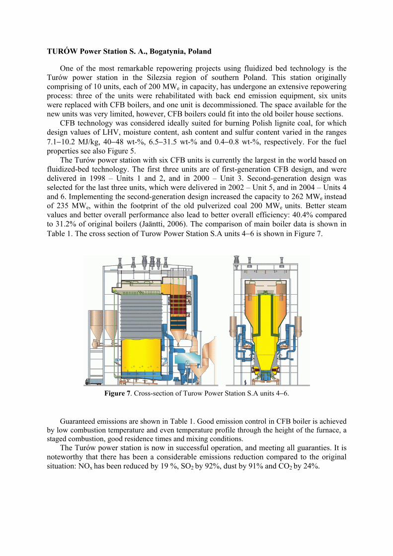
One of the most remarkable repowering projects using fluidized bed technology is the Turów power station in the Silezsia region of southern Poland. This station originally comprising of 10 units, each of 200 MWe in capacity, has undergone an extensive repowering process: three of the units were rehabilitated with back end emission equipment, six units were replaced with CFB boilers, and one unit is decommissioned. The space available for the new units was very limited, however, CFB boilers could fit into the old boiler house sections. CFB technology was considered ideally suited for burning Polish lignite coal, for which design values of LHV, moisture content, ash content and sulfur content varied in the ranges 7.1−10.2 MJ/kg, 40−48 wt-%, 6.5−31.5 wt-% and 0.4−0.8 wt-%, respectively. For the fuel properties see also Figure 5. The Turów power station with six CFB units is currently the largest in the world based on fluidized-bed technology. The first three units are of first-generation CFB design, and were delivered in 1998 – Units 1 and 2, and in 2000 – Unit 3. Second-generation design was selected for the last three units, which were delivered in 2002 – Unit 5, and in 2004 – Units 4 and 6. Implementing the second-generation design increased the capacity to 262 MWe instead of 235 MWe, within the footprint of the old pulverized coal 200 MWe units. Better steam values and better overall performance also lead to better overall efficiency: 40.4% compared to 31.2% of original boilers (Jaäntti, 2006). The comparison of main boiler data is shown in Table 1. The cross section of Turow Power Station S.A units 4−6 is shown in Figure 7.
Figure 7. Cross-section of Turow Power Station S.A units 4−6.
Guaranteed emissions are shown in Table 1. Good emission control in CFB boiler is achieved by low combustion temperature and even temperature profile through the height of the furnace, a staged combustion, good residence times and mixing conditions. The Turów power station is now in successful operation, and meeting all guaranties. It is noteworthy that there has been a considerable emissions reduction compared to the original situation: NOx has been reduced by 19 %, SO2 by 92%, dust by 91% and CO2 by 24%.

Table 1. Main boiler data for Turow Power Station S.A units 1−6 Boilers No. 1−3 No. 4−6 Capacity MWt 528.9 557 Main steam flow kg/s 185.4 195.5 Main Steam Pressure bar 131 169 Main Steam Temperature °C 540 565 Reheated Steam Pressure bar 24 39 Reheated Steam Temperature °C 540 585 Guaranteed emissions, 6 % O2 content, dry flue gas NOx mg/Nm3 371 SOx mg/Nm3 347 CO mg/Nm3 150 Dust mg/Nm3 50
Elektrownia Jaworzno III S.A., Jaworzno, Poland
In the Jaworzno Project three old pulverized coal fired boilers were replaced with two 70 MWe CFB boilers firing local high-ash and high-moisture bituminous coal. In addition, these boilers can fire, up to 50% of energy input, coal slurry that is delivered from the adjacent coal-mines (Figure 8). Fuel properties are summarized in Figure 5.
The boilers utilize second-generation of Foster Wheeler CFB design with compact separators and INTREXTM superheaters (Figure 9). Steam and feed-water data of one boiler at nominal capacity are:
Total Heat Output MWth 180 Steam Flow kg/s 72.2 Steam Pressure bar 137 Steam Temperature °C 540 Feedwater Temperature °C 220
´
Figure 8. Coal slurry.
Figure 9. Cross-section of Elektrownia Jaworzno III S.A
CFB unit.

The boilers are in commercial operation since November 1999.
AS Narva Elektrijaamad, Narva, Estonia
Estonia’s electricity generation is more than 90% based on combustion of oil-shale. AS Narva Elektrijaamad owns and operates two largest oil-shale-burning power plants in Estonia (and worldwide), Eesti and Balti, located near the town of Narva. A combined installed capacity of two power plants is 2,705 MW of electricity and 589 MW of district heating. Plants, originally build with pulverized fuel (PF) technology, were commissioned during the years 1959–1973. Due to their age and poor economic and environmental performance related to PF firing of oil shale the utility decided to repower two 200 MWe units with fluidized-bed technology. After preliminary investigations and pilot-scale combustion tests, CFB technology was found to be the most suitable for oil shale firing in terms of process behavior and gaseous emissions. The engineering, procurement and construction (EPC) contract for the design and supply of four new 100 MWe CFB boilers was signed between AS Narva Elektrijaamad and Foster Wheeler Energia Oy in May 2001. The project also included the modernization and upgrading of two existing 200 MWe steam turbine-generators to 215 MWe. The first of the new blocks, Eesti block 8, started commercial operation in February 2004 and was followed by Balti block 11 later during the same year. The units are designed to produce 90 kg/s of superheated steam at 13.1 MPa pressure and 540 °C temperature, and reheat steam at 2.7 MPa pressure. The load range 40-100 % of MCR. Estonian oil shale is a very difficult-to-burn fuel due to its unique properties (see Figure 5). High alkali and chlorine content in oil-shale ash has caused significant corrosion and fouling problems in PF units, resulting in decreased availability. Gaseous emissions, especially SO2 and particulate emission, have been high. In CFB combustion the SO2 emission is considerably reduced due the inherent limestone content of oil-shale ash, which favors sulfur capture in CFB conditions. SO2 and NOx emissions have been reduced by 90% and 30%, respectively, while particulate emission has decreased significantly compared to the old PF units with less efficient electrostatic precipitators (ESP). Improved efficiency and decreased carbonate decomposition in CFB has decreased the CO2 emission per produced power unit by nearly 24%. In the CFB boilers, fouling and corrosion problems in the convective superheaters have been prevented by careful choice of steam temperature for each superheating stage and by using effective heat surface cleaning methods. INTREXTM superheaters are used as the last super-/reheating stage, and refractory- lined separators as second superheating stage, allowing lower steam temperature to be used in convective super-/reheater sections where the risk of high-temperature corrosion is highest. The new CFB boilers use pneumatic fuel feeding with many feeding points, resulting in good fuel mixing and providing favorable conditions for sulfur binding in the lower furnace (Figure 10). The careful CFB boiler design has resolved the problems related to oil shale combustion: during the first year of commercial operation no signs of significant fouling or corrosion of heat exchangers has occurred in the new boilers at the Narva Power Plants. Improved availability, lower maintenance costs and higher efficiency of the new units have significantly improved the unit’s economics. According to the performance tests, the net efficiency of the CFB units is 38–39%, whereas in the PF units it is in the range of 29–30%. A big part of the efficiency improvement is deriving from the lower carbonate deposition and higher sulfation rate in CFB combustion, the effect of which is about 0.4 MJ/kg or 5% comparing with PF (Hotta et al., 2005).

Figure 10. The basic design of the CFB boilers at the AS Narva Eletkrijaamad power stations.
Eesti and Balti power plants were granted a transition period concerning the EU Large Combustion Plant Directive emission limits until the end of 2015, after which the old PF blocks must be out of service. Due to positive experiences from two first units repowered with CFB technology, Narva Power Plants is planning to proceed by repowering two to five additional 200 MWe units with CFB technology, the best available technology for oil shale firing.
Poludniowy Koncern Energetycny (PKE), Lagisza, Poland
CFB is not only suitable for hard-to-burn fuels, but the technology is also ideally suited for quality bituminous coal. Through a continuous scale-up and development process, CFB technology has now reached medium utility scale with once-through supercritical boiler technology. Utilization of Siemens' BENSON low mass-flux vertical tubing technology offers some clear advantages for CFB technology including a lower pressure drop over the furnace tubing, resulting in less power needed for feed water pumps and lower auxiliary power consumption. The combustion temperature in a CFB is homogenous both vertically and horizontally, which means that the heat flux is relatively uniform, and the risk of overheating is not present as it is in conventional technology with a heat flux that can be up to three times higher locally. The first company to benefit from OTU CFB technology with supercritical steam parameters will be the Polish utility, Poludniowy Koncern Energetyczny S.A. (PKE). The new 460 MWe (gross) unit will replace old power blocks of Lagisza Power Plant. The existing blocks were erected in 1960’s and consist of seven units (110-125 MWe each). Two of them will be shut down after the new 460 MWe unit is commissioned. The new boiler will be built adjacent to the old boilers and many of existing plant systems like coal handling and water treatment will be renovated and utilized for the new CFB unit. Main fuel for the boiler is bituminous coal. The source of fuel consists of 10 local coal mines with wide range of coal parameters, proving once more the fuel flexibility of the CFB technology. Table 2 summarizes parameters of design fuel and overall fuel range. Boiler design is optimized with a possibility for combustion of additional fuels. Main additional fuel is coal slurry that is available in large amounts in local coal mines. Due to CFB technology characteristics, wet coal slurry can be combusted with 30% share by fuel heat input. Coal

washing rejects can also be burned in form of dry coal slurry granulates with a share up to 50% of heat input. Boiler is designed also to utilize biomass fuels up to 10% of fuel input. The biomass feeding equipment is included in the delivery as an option.
Table 2. Fuel properties for the Lagisza project
Coal range Coal slurry range (max 30% input)
Lower heat value MJ/kg 18−23 7−17 Moisture content % 6−23 27−45 Total ash content % 10−25 28−65 Sulfur content % 0.6−1.4 0.6−1.6
Table 3. Boiler data for the Lagisza 460 MWe CFB boiler
Maximum continuous flow kg/s 359.8
Minimum continuous flow kg/s 143.9 HP steam pressure at turbine inlet MPa 27.50 HP steam temperature at turbine inlet °C 560 Cold reheated steam flow kg/s 306.9 Cold reheated steam pressure MPa 5.46 Cold reheated steam temperature °C 314.3 RH steam temperature at IP turbine inlet °C 580 Feed water temperature °C 289.7
The Lagisza CFB boiler is dimensioned according to data given in Table 3. The general boiler layout was based on the conventional in-line arrangement already applied for Units 4−6 of the Turów power plant. Figure 11 shows schematics of the boiler. Detailed description of the once-through boiler design and related aspects can be found in Venäläinen, Psik, 2004. The emission requirements for the Lagisza boiler are according to European Union directive for Large Combustion Plants, and considerable emission reduction is expected compared to existing PF unit. The emissions of sulfur dioxide are controlled with limestone feeding into the furnace. With the design coal a sulfur reduction of 94% is required, and that shall be achieved in the CFB with a calcium to sulfur molar ratio of 2.0−2.4. The nitrogen oxide emissions are controlled with low combustion temperature and staged combustion. There are also provisions made for a simple ammonia injection system (SNCR), however that is not required on design coals. Compared to original plants, NOx is expected to be reduced by 71%, and CO2 by 28%. Particulate emissions are controlled by electrostatic precipitator. The plant efficiency is expected to be improved from 34.7% to nearly 44%.

Figure 11. The 460 MWe once-through CFB at PKE, Lagisza.
Scaling up once through supercritical CFB boilers to 800 MWe
Further development of CFB technology to even larger sizes and higher plant efficiencies is an ongoing challenge. Foster Wheeler and Endesa, together with a group of other interested companies from Germany, Greece, Finland and Spain have initiated a study for an 800 MWe power plant with ultra-supercritical steam parameters based on CFB technology. The group has been working on a conceptual boiler design to better understand the feasibility of a large CFB design. The preliminary results show that the actual scale-up of critical CFB components such as the furnace, solids separators, and fluidized bed heat exchangers to 800 MWe is possible. The actual required scale-up of the dimensions and size of the plant components is quite moderate due to the modular approach adopted for the boiler design (Hotta, Venäläinen, 2006). Foster Wheeler will be ready to offer 800 MWe CFB units by the end of 2009.
MULTI-FUEL COMBUSTION IN CFB BOILERS
Foster Wheeler is continuously working on improving the co-combustion capability of its CFB boilers. From a technical standpoint, co-firing of biomass and waste appears best in large coal-fired units, where all available biomass and waste can amount to only a minor share of the thermal input. In return, the coal-fired unit benefits from more economical fuels and better CO2 performance. In addition, co-combustion of biomass and waste fuels is an effective method to counteract agglomeration, fouling and corrosion, difficulties which often arise during combustion of these types of fuel. In co-firing case, compounds contained in coal capture the problematic elements from biomass and waste, with no additional losses or costs (Coda Zabetta et al., 2008).

National Power Supply Co., Ltd. (NPS) Power Plant, Tha Toom, Thailand
The National Power Supply Co., Ltd. (NPS) Power Plant, located in Tha Toom village of Prachinburi province in Thailand, started commercial operation in February 1999 (Figure 12). The power plant is equipped with two identical units of 150 MWe or 370 MWth. Each unit is designed to produce 134 kg/s of superheated steam at 162 bar(a) pressure and 542 °C temperature, and 122 kg/s of reheat steam at 542 °C temperature and pressure of 16 to 38 bar(a) depending on boiler load. The NPS Power Plant is feeding 60% of its power output to the Electricity Generating Authority of Thailand (EGAT) under Thailand’s small power producer (SPP) program. The process steam and the remainder of the power are sold to local customers of the Industrial Park 304 and to the nearby Advance Agro pulp and paper mill.
Figure 12. Two CFBs at the NPS power plant in Thailand.
The main fuels used in both boilers are anthracite and/or bituminous coal, and additionally, up to 50 en-% the boilers are designed to co-fire local biomass: rice husk and eucalyptus bark. Rice husk is purchased from the local suppliers while eucalyptus bark is a waste product from the nearby Advance Agro pulp and paper mill. As it can be seen from Figure 5, chemical properties of the biomass fuels differ significantly between each other, and from those of coals. Rice husk is a very special biomass fuel with ash content of 15−20 wt-% in dry solids, which is higher compared to many other biomass fuels. Rice husk ash contains over 90% SiO2 in most cases, making it very different from the straws of other cereals and even the rice straw ash. It does not cause fouling or slagging, but has slightly erosive effect due to a large particle size and sharp edged SiO2 particles in ash. The erosivity of rice husk is high enough to “sand blast” to some extent the boiler when co-fired with for example eucaliptus bark that have ash with fouling propensity (Hiltunen et al., 2008). Eucalyptus bark is another exceptional biomass that can contain very high contents of chlorine. Concentrations up to 0.98 w-% have been analyzed, although normally the values are 0.2–0.3 w-% in dry solids (Hiltunen et al, 2008). Combined with ash composed mainly of calcium and potassium compounds, such high chlorine level is known to increase boiler fouling, and superheater corrosion.

Fired in high efficiency boilers with high steam temperatures and pressures, the negative properties of such biomass fuels and their ashes are amplified. Nevertheless, thanks to proper understanding of interactions among ashes of co-fired fuels, and reactions of flue gas components with the ash components, both rice husk and eucalyptus bark have been efficiently utilized in two NPS boilers that feature the second-generation CFB design with INTREXTM superheaters. The boilers have been in successful operation for nearly ten years, with good availability.
CONCLUSIONS
Circulating fluidized bed (CFB) boiler technology has developed to meet utility-scale requirements. Owning to high efficiency, excellent multi-fuel capability and low emissions of major pollutants (SO2, NOx, CO, CO2, particulates etc.) the technology offers reliable solution for both repowering of old power plants and building a new plant. CFB technology has proved excellent with low-grade fuels, such as lignite and low-grade bituminous coals, coal washery rejects, oil shale, and with good quality fuels. Co-combustion of various types of biomass and waste fuels in CFB boilers has proven as efficient and economic way to reduce CO2 emissions, and to minimize landfiling. CFB technology is today commercial for sizes up to 500 MWe with once-through supercritical technology, and by the end of 2009 Foster Wheeler will be ready to offer 800 MWe CFB units.
LITERATURE
Barišić, V.; Hupa M. On changes in bed-material particles from a 550 MWth CFB boiler burning coal, bark and peat. Fuel 86, 2007, 464−468.
Coda Zabetta, E.; Barišić, V.; Peltola, K.; Hotta, A. Foster Wheeler Experience with Biomass and Waste in CFBs. 33rd International Technical Conference on Coal Utilization & Fuel Systems, Clearwater, Florida, USA, 2008.
Hiltunen, M.; Barišić, V.; Coda Zabetta, E. Combustion of Different Types of Biomass in CFB Boilers. 16th European Biomass Conference, 2008,Valencia, Spain.
Hotta, A.; Nuortimo, K.; Eriksson, T.; Palonen, J.; Kokki, S. CFB Technology Provides Solutions to Combat Climate Change. 9th International Conference on Circulating Fluidized Beds, 2008, Hamburg, Germany.
Hotta, A.; Uus, M.; Parkkonen, R. Enhanced Performance Using CFB Boilers to Fire Oil Shale Compared to PC Technology. POWER-GEN Europe 2005, Milan, Italy.
Hotta, A.; Venäläinen, I. Design and Scale-up Philosophy of One-through CFB Boilers with Supercritical Parameters. VGB PowerTech 4, 2006, 66−71.
Jäntti, T.; Eriksson, T.; Hotta, A.; Hyppänen, T.; Nuortimo, K. Circulating Fluidized-bed Technology − toward zero CO2 Emissions. POWER-GEN Europe 2006, Cologne, Germany.
Navarrete Fernández, E. Polish Operating Experience from Burning Coal, Coal Washery Reject and Brown Coal in Circulating Fluidized Bed Boilers. Enerji 2003, Istanbul, Turkey.
Psik, R.; Jablonski, J.; Wyszynski, J. Turów Rehabilitation Project − The World’s Largest CFB Repowering Project, POWER-GEN Europe, 2005, Milan, Italy.

Pyykkönen, A.; Hotta, A. Foster Wheeler’s 2*150 MWe CFB Boilers Started up Successfully in NPS Power Plant in Thailand. POWER-GEN Asia 2000, Bangkok, Thailand.
Phyllis: The Composition of Biomass and Waste; Energy Research Centre of Netherlands (ECN), Unit Biomass: Petten, The Netherlands (http://www.enc.nl.phyllis)
Venäläinen, I.; Psik, R. 460 MWe Supercritical CFB Boiler Design for Lagisza Power Plant. POWER-GEN Europe 2004, Barcelona, Spain.