foundation design options report
TRANSCRIPT

St. Croix River Crossing Preliminary EngineeringFoundation Design Options Report
Prepared for:Minnesota Department of Transportation andWisconsin Department of Transportation
Prepared by:Parsons Brinckerhoff
June 2010


St. Croix River Crossing Preliminary EngineeringFoundation Design Options Report
June 2010 iii
Table of Contents1 Introduction ............................................................................................................................. 1-1
1.1 Project Description ...................................................................................................... 1-11.1.1 Mn/DOT Bridge 82045 (WisDOT Bridge B-55-224) (Mainline TH 36 and STH 64) .......... 1-11.1.2 Mn/DOT Bridge 82047 (TH 36WB off-ramp to TH 95) .................................................. 1-11.1.3 Mn/DOT Bridge 82048 (TH 36EB on-ramp from TH 95) ................................................ 1-21.2 Purpose and Scope of Work......................................................................................... 1-2
2 Previous Investigations ............................................................................................................ 2-1
3 Site Conditions ......................................................................................................................... 3-13.1 Geology ....................................................................................................................... 3-13.2 Subsurface Conditions ................................................................................................. 3-23.2.1 Soft, Organic River Silts ................................................................................................ 3-23.2.2 Minnesota Overburden ............................................................................................... 3-23.2.3 Wisconsin Overburden ................................................................................................ 3-43.2.4 Bedrock ....................................................................................................................... 3-43.3 Soil and Rock Properties .............................................................................................. 3-63.3.1 Soft, Organic River Silts ................................................................................................ 3-63.3.2 Minnesota Overburden ............................................................................................... 3-73.3.3 Wisconsin Overburden ................................................................................................ 3-73.3.4 Bedrock ....................................................................................................................... 3-83.4 Groundwater Conditions ........................................................................................... 3-10
4 Foundation Design Options ...................................................................................................... 4-14.1 General ....................................................................................................................... 4-14.2 Minnesota Onshore Spans ........................................................................................... 4-14.3 St. Croix River Spans .................................................................................................... 4-44.4 Wisconsin Onshore Spans ............................................................................................ 4-74.4.1 Drilled Shafts ............................................................................................................... 4-84.4.2 Steel Piles .................................................................................................................... 4-9
5 Future Studies and Analyses .................................................................................................... 5-15.1 General Considerations ............................................................................................... 5-15.2 Deep Foundation Construction Considerations, Testing and Monitoring ...................... 5-15.2.1 Construction and Testing Considerations for Driven Piles ............................................ 5-15.2.2 Construction Considerations for Drilled Shafts: ............................................................ 5-2
6 Study Limitations ..................................................................................................................... 6-1
References ..................................................................................................................................... R-1
Figures ........................................................................................................................................... F-1
Tables
Table 3-1. Conceptual Geotechnical Parameters 3-6

iv June 2010
Acronyms and Abbreviations
CPT cone penetrometer tests
CSL cross-hole sonic logging
DB Design-Build
kips thousand pounds
ksf thousand pounds (kips) per square foot
L/D length-to-diameter (ratios)
Mn/DOT Minnesota Department of Transportation
NDT non-destructive testing
O-cell Osterberg load cell
PB Parsons Brinckerhoff (PB Americas, Inc.)
pcf pounds per cubic foot
PDA pile driving analyzer
psf pounds per square foot
psi pounds per square inch
RQD rock quality designation
SFEIS Supplemental Final Environmental Statement
SID shaft inspection device
SPT standard penetration test
UC unconfined compressive
UP R/R Union Pacific Railroad
USCS Unified Soil Classification System
UU unconsolidated-undrained
WEA Wave Equation Analysis
WisDOT Wisconsin Department of Transportation
WOH weight of hammer
Certification
I hereby certify that this report was prepared by me or under my direct supervision,and that I am a duly Licensed Professional Engineer under the laws of the State ofMinnesota.
Frank Pepe, Jr.Reg. No. 46151June 15, 2010

St. Croix River Crossing Preliminary EngineeringFoundation Design Options Report
June 2010 1-1
1 Introduction
1.1 Project Description
Parsons Brinckerhoff (PB) has been retained by the Minnesota Department ofTransportation (Mn/DOT) to perform conceptual design and associated services forthe proposed St. Croix River Crossing. The services are within the overall St. CroixRiver Crossing Project which is defined as Minnesota S.P. 8214-114,S.P. 8214-(82045), S.P. 8214-(82047), S.P. 8214-(82048) and Wisconsin ProjectI.D. 1550-00-02. These services are part of the Preferred Alternative Package for theSt. Croix River Crossing Project as documented in the 2006 Supplemental FinalEnvironmental Impact Statement (SFEIS).
The overall St. Croix River Crossing Project termini are along TH 36/STH 64 from TH 5in Minnesota to 150th Avenue in Wisconsin (Figure 1). The segment of TH 36proposed for reconstruction in Minnesota is located approximately 1,050 feet eastof the Washington/Norell intersection and the St. Croix River in Oak Park Heightsand Stillwater. The new river crossing proposed for construction is located approxi-mately 7,550 feet south of the Lift Bridge and downtown Stillwater, Minnesota,along the Minnesota side of the crossing of the St. Croix River and approximately6,450 feet south of the Lift Bridge along the Wisconsin shoreline. The segment ofSTH 64 proposed for construction in Wisconsin is located between the St. Croix Riverand the 150th Avenue overpass in the Town of St. Joseph.
The proposed St. Croix River Crossing is comprised of three separate bridges that areidentified as Mn/DOT Bridge Nos. 82045, 82047, and 82048.
1.1.1 Mn/DOT Bridge 82045 (WisDOT Bridge B-55-224) (Mainline TH 36 andSTH 64)
Bridge No. 82045 spans Minnesota TH 95, the Union Pacific Railroad (UP R/R),wetlands, and the St. Croix River. Its west abutment is located immediately west ofTH 95. Its east abutment is located on the Wisconsin side of the river. The totalbridge length from abutment to abutment is approximately 5,040 feet. The bridge iscomprised of main river spans with a length of approximately 3,460 feet andwesterly approach spans with a length of approximately 1,610 feet. The river spanshave an extradosed superstructure that combines concrete box girders with cablestays. The approach spans have a concrete box girder superstructure. The transitionfrom approach spans to river spans occurs at a common pier located just inland fromthe Minnesota shoreline. The Minnesota approach spans to the river crossing havelengths ranging from 160 to 300 feet.
1.1.2 Mn/DOT Bridge 82047 (TH 36WB off-ramp to TH 95)
Bridge No. 82047 spans the UP R/R, local roadways, and wetlands. This bridge has aconcrete box girder superstructure that frames into an approach span of BridgeNo. 82045. The typical section has a variable lane width ranging from 16 to 32 feet,with 4-foot inside and outside shoulders.

St. Croix River Crossing Preliminary EngineeringFoundation Design Options Report
1-2 June 2010
1.1.3 Mn/DOT Bridge 82048 (TH 36EB on-ramp from TH 95)
Bridge No. 82048 spans the UP R/R, local roadways, and wetlands. This bridge has aconcrete box girder superstructure that frames into an approach span of BridgeNo. 82045. The typical section has a variable lane width ranging from 16 to 32 feet,and 4-foot inside and outside shoulders.
1.2 Purpose and Scope of Work
The main focus of this Foundation Design Options Report has been to present ageneral discussion of the geotechnical and geologic conditions which are anticipatedto be encountered along the proposed alignment, consider the geotechnicalconstraints for the potential foundations of the bridge structures, and to identifyfeasible conceptual foundation alternatives for each bridge structure.
PB has performed this conceptual geotechnical evaluation for the St. Croix RiverCrossing project in accordance with its Contract with Mn/DOT. The purpose of thisevaluation was to:
Perform a conceptual level evaluation to screen potential foundation alterna-tives and identify feasible foundation types for each structure based on factorssuch as design requirements, constructability, subsurface conditions and cost.Perform conceptual level axial static and deformation analyses of the identifiedfoundation alternatives for each structure to estimate vertical capacity andpenetration requirements to support bridge loads.Assess lateral displacement characteristics of the selected foundation alternativefor each structure and evaluate the lateral load capacity.Develop conceptual level foundation recommendations for each structure basedon both design requirements and constructability considerations.
The geotechnical data and borings used for these conceptual evaluations wereperformed and provided by Mn/DOT. The boring logs and geotechnical investigationrecords on which the conceptual recommendations presented herein were baseddepict subsurface conditions only at the specific exploration location and at theparticular time designated on the logs or geotechnical investigation record. Subsur-face conditions at other locations may differ from conditions occurring at the boringand investigation locations. Also, the passage of the time may result in a change inthe subsurface condition at an investigation location.
This report specifically does not address environmental issues and issues related togroundwater and soil contamination.

St. Croix River Crossing Preliminary EngineeringFoundation Design Options Report
June 2010 2-1
2 Previous Investigations
Existing subsurface information from previous geotechnical investigations wasprovided by Mn/DOT and assessed for this report. The sources of the existingsubsurface information included previous investigations performed in earlier phasesof project. These investigations included borings conducted along the preferredalignment as presented in the 2006 SFEIS as well as borings conducted along twoadditional alignment alternatives located north of the preferred alignment. Theboring locations of the phases of investigations are presented in Figure 1. Specificinformation provided includes the following:
The first phase of borings conducted by Mn/DOT for the project was performedfrom November 1991 through August 1996. The alternative alignment, chosen in1995 for design, is similar in location to the preferred alignment onshore on theMinnesota side of the crossing; however, the Wisconsin abutment was locatedapproximately 900 feet to the north of the preferred alignment. The investiga-tion, conducted over the course of nearly 5 years, consisted of 55 boringslocated on land in Minnesota, 21 borings within the St. Croix River, and 10borings on land in Wisconsin. The borings are designated T-01 through T-89. Thelaboratory testing performed included natural water content, Atterberg Limits,grain size analyses, organic content determinations, unconsolidated-undrained(UU) triaxial tests, unconfined compressive (UC) tests, and splitting tensile tests.The second phase of borings conducted for the project was performed along analignment located approximately 2,700 feet upstream from the preferredalignment. These borings, designated T-01 through T-17, were all performedwithin the St. Croix River. T-01 and T-02 were performed in November 1998 andT-03 through T-17 were performed in September and October of 1999. Thelaboratory testing performed included natural water content, grain size analyses,organic content determinations, UU triaxial tests, and UC tests.The third phase of borings was performed along the preferred alignment fromAugust through November 2005. A total of 11 borings, designated T201 throughT211, were conducted at designated pier locations within the St. Croix River.Boring depths ranged from 81.7 to 217.3 feet, with a total length of 1720 feetdrilled. Two cone penetrometer (CPT) tests were also conducted within the river.The CPTs, designated ct203 and ct207, were conducted on November 29, 2005and had depths of 69.8 and 65.9 feet, respectively. The laboratory testingperformed included natural water content, organic content determinations, UUtriaxial tests, and UC tests. The results of this phase of borings are presented in aMemorandum from Mr. Gary Person and Mr. Charles Howe of Mn/DOT toMr. Dan Dorgan of Mn/DOT dated August 4th, 2006.The fourth and final phase of borings was performed along the preferredalignment from June 25 through July 30, 2009. A total of 6 borings, designatedT302 through T305, W1 and W2, were conducted at designated pier locationswhich did not contain detailed geotechnical information from the aboveinvestigations at the time of their performance. Four of the borings, T302

St. Croix River Crossing Preliminary EngineeringFoundation Design Options Report
2-2 June 2010
through T305, were performed onshore on the Minnesota side and the othertwo, W1 and W2, were performed onshore on the Wisconsin side. Boring depthsranged from 114 to 267 feet, with a total length of 972 feet drilled. The labora-tory testing performed included organic content determinations and UC tests.
The boring logs and laboratory test data referenced above are available fromMn/DOT. Complete geotechnical data, including boring and coring logs, is madeavailable for reference by Mn/DOT at www.mrr.dot.state.mn.us/geotechnical/foundations/stcroix.asp
Generally, all of the subsurface information collected within the subsurfaceinvestigations noted above was considered for use in this conceptual evaluation.However, while the earlier two phases of investigations provide information whichhelped draw conclusions and interpolations, more weight was given to those boringsconducted within the third and fourth phases because these borings were per-formed at current design pier locations. An exception to this are those boringsconducted within the first phase which are located near the preferred alignment’sapproach structures on the Minnesota side of the crossing. Due to lack of recentinformation in these areas, these borings were also considered.
In October 1995, Mn/DOT implemented a load test program to develop designparameters for deep foundations. The location of the load testing was generally inthe vicinity of the bridge alignment of the preferred alignment onshore on theMinnesota side of the crossing; however, the testing for the Wisconsin abutmentwas located approximately 900 feet to the north of the preferred alignment. Twodrilled shafts located onshore on the Minnesota side and one driven pipe pilelocated within the St. Croix River, were installed and tested by a contractor undercontract to Mn/DOT. A subsequent summary report to document and interpret theinstallation and load testing of the foundation elements was prepared by O’Neill andMajano (January 1996). The drilled shafts were constructed and tested to determineunit side shear and end bearing and unit lateral resistance for purposes of develop-ing design parameters for compression and lateral loading of foundations socketedinto the bedrock formations encountered at the project site. The test pile was drivenand tested to determine factors for the analysis of buckling and to determine pulloutresistance of the prototype pipe pile. The load test program was not able to addressthe differing overburden conditions that occur between the Minnesota andWisconsin sides of the bridge. Attempts were made by the researchers to addressscaling effects due to foundation size and diameter. The program encountereddelays during construction and excavation stability issues which resulted in probableaccumulation of sediments at the base of the test shafts that likely impacted theresults of the load tests. A brief summary of the results of the drilled shaft load testsare as follows:
Values for maximum unit-side shear resistance (nominal) for 8-foot diameterdrilled shaft rock sockets in compression recommended in the report were

St. Croix River Crossing Preliminary EngineeringFoundation Design Options Report
June 2010 2-3
6.6 thousand pounds (kips) per square foot (ksf) at a depth of 2 feet into thesandstone and 9.0 ksf at 30 feet.The information on end bearing from the axial test socket was meager due tothe accumulation of sediments at the base. A nominal value of 19.2 ksf wasrecommended in the report for an 8-foot diameter rock socket a depth of 30 feetinto the sandstone.
The reader is referred to the O’Neill and Majano report for a complete summary anddescription of the load test program.


St. Croix River Crossing Preliminary EngineeringFoundation Design Options Report
June 2010 3-1
3 Site Conditions
3.1 Geology
This section describes the general geology of the project area on a regional scale,including the various rock types, surficial deposits, structural features, and topo-graphy, as available in the literature. The information presented here provides ageneral geologic history.
The proposed St. Croix River Bridge site is located south of Stillwater, Minnesota onTH 36 continuing across the St. Croix River to west-central Wisconsin. The site issituated near the physiographic boundary between the Laurentian Upland and theInterior Lowland. The topography within the project area is dominated by hills of theSt. Croix Moraine, constructed by Labradorean ice during the late Wisconsinglaciation.
The project site is underlain by Early Paleozoic Era (525 to 400 million years old),Upper Cambrian Series marine sedimentary bedrock. Shallow Paleozoic seasadvanced, covering southeastern Minnesota and parts of adjacent states, andretreated repeatedly during most of this time. As a result of this transgression andregression, sand accumulated in nearshore bars, on beaches and in sand dunes.Carbonate accumulated in small banks or reefs, and as tabulate layers on theseafloor, and silt and clay formed mudflats which later solidified to form the presentday sedimentary rock.
The rock units encountered in the project area belong to the Jordan Sandstone,St. Lawrence and Franconia Formations. The upper part of the Jordan Sandstone ismedium- to coarse-grained, friable, quartzose sandstone and is trough crossbedded. The lower part is primarily fine-grained sandstone, feldspathic, massivelybedded and bioturbated. The St. Lawrence Formation consists of dolomitic shale andsiltstone that is generally thinly bedded. The contact between the St. LawrenceFormation and the overlying Jordan Sandstone is gradational. Underlying theSt. Lawrence Formation is the Franconia Formation composed of very fine-grainedglauconitic, quartzose sandstones.
The majority of the bedrock in the project area is concealed beneath a mantle ofunconsolidated Quaternary (Pleistocene and post-glacial sediments of the Holocene)deposits that can be over 350 feet thick in some of the deeper buried valleys. Thesurficial deposits in the project area consist of organic deposits, including peat andorganic-rich sediments, and lacustrine deposits, including sand and loamy sand withlocal organic-rich deposits. Bedrock exposures and outcrops are common along thebluffs within the Mississippi and St. Croix River Valleys and short steep tributariesdraining into them.
The regional dip of sedimentary strata toward the west and south reflect the projectlocation’s position on the eastern margin of the Twin Cities basin. The basin wasdeveloped as a result of the reactivation of the Proterozoic faults, many step-like

St. Croix River Crossing Preliminary EngineeringFoundation Design Options Report
3-2 June 2010
smaller faults and folds with generally small displacements of 100 feet for folds and50 to 150 feet for faults, during Paleozoic time. The Hudson-Afton anticline, approxi-mately 4 miles south of the project site, is one of the largest folds. It overlies a block-faulted zone in the Proterozoic rocks along the eastern side of the Twin Cities basin.
3.2 Subsurface Conditions
This section summarizes the general subsurface conditions at the St. Croix RiverCrossing project location as determined from the geotechnical information obtainedfrom the previous investigations as provided by Mn/DOT. General brief descriptionsof the strata encountered during the investigations are presented.
Generalized subsurface profiles developed for the project site are shown in Figures 2through 6. Stratification may contain differing soil materials with transitionsoccurring gradually. Stratigraphic features shown on the subsurface profiles aredetermined by interpretation between borings. Exact locations and transitions areapproximate and may differ from those portrayed. In view of the inherently variablenature of the geological environment and the previous construction activity sur-rounding the project site, particularly near the Minnesota approaches, variationsfrom the interpreted soil profiles should be expected. Based on the informationobtained from the previous geotechnical investigations performed at the projectsite, the site is underlain by four principal soil strata. These are the soft organic siltstypically encountered at the mudline within the river, the overburden materials onthe Minnesota side, the overburden material on the Wisconsin side, and bedrock.These four strata are discussed below.
3.2.1 Soft, Organic River Silts
Data from the subsurface investigation program revealed that varying thickness ofsoft, organic river silts are present within the extent of the St. Croix River. Thethickness of the silt materials was approximated to range from nearly 75 feet nearthe center of the river channel and generally tapering out totally near the riveredges.
Typically, standard penetration tests (SPT) were not performed within the soft,organic river silt layer, and therefore SPT N-values were generally not available toassess the consistency of this deposit. However, based on the sample descriptions,laboratory testing and knowledge of the depositional mode of these deposits, theriver silt materials generally consist of very soft, organic to highly organic plastic silt.Typically, wood or shells were encountered within the samples as well. According tothe Unified Soil Classification System (USCS) guidelines, the soft organic silt materialscan generally be classified as OH.
3.2.2 Minnesota Overburden
The overburden materials located on and near the Minnesota side of the crossingvary in thickness considerably along the bridge alignment, ranging from less than10 feet offshore to over 74 feet below the ground surface. At Pier 1 of the mainline

St. Croix River Crossing Preliminary EngineeringFoundation Design Options Report
June 2010 3-3
bridge (Bridge No. 82045) borings were advanced to a depth of 74 feet below theground surface without encountering bedrock. Generally, the Minnesota over-burden materials gradually decrease in thickness from the west abutments towardsthe river along the profile for the approach structures and typically range between35 to 40 feet thick from approximately Sta. 458+00 to 471+00 along the mainline.
Based on the available subsurface information and borings, the Minnesota over-burden consists of various soil types. Due to the extensive previous construction andsite activity in the area, the overburden materials may include fill materials locatednear the ground surface. Fill materials generally consist of sand and gravel and inmany cases appears to have been derived from the natural deposits that occur overthe site. The fill materials are typically described as having pieces of wood, brick,stone chips, and other miscellaneous manmade debris within the retrieved sample.Also, in Boring T-05, the fill material encountered was described as “tailings from apower plant stack” from 3.3 feet to 6.9 feet below the ground surface.
Also encountered within the Minnesota overburden materials are pockets and layersof organic loam and fibrous peat. According to the USCS guidelines, the peatmaterial can generally be classified OL. The organic material appears to be discon-tinuous along the bridge alignments and was observed randomly across the site.When encountered, the organic material ranged in thickness from approximately1 foot up to 9 feet. In borings where the organic material was not encountered, it ispossible that the sampling intervals were larger than the thickness of the organicmaterial and, as a result, was not observed at the elevation of the samples them-selves but may be present between sampling intervals.
The remaining material encountered within the Minnesota overburden generallyconsists of glacially deposited material with considerable variations in the percent-ages of the various components over a short distance. These materials weregenerally described as sand, silt, or clay with varying percentages of other materialsincluding gravel sized particles. According to the USCS guidelines, these materialscan generally be classified as SP, SM, ML, and CL. Minnesota overburden locateddirectly above the bedrock generally consisted of the glacially deposited materials.
The SPT N-values observed within the Minnesota overburden ranged from twoblows per foot to, in some cases, greater than 50 blows for six inches of penetration(split spoon refusal). Typically, lower blow counts were observed within the organicand fill materials located near the ground surface. Furthermore, in some cases, therefusal of the sampler was likely caused by the presence of gravel restricting theadvancement of the sampler rather than refusal caused by the relative density orstiffness of the geologic material. Therefore, these SPT N-values could be higher dueto the gravel content in some samples and therefore the very high values may notbe fully representative of the density of the deposit. Typically, the SPT N-valuesindicate that the consistency of the stratum ranges from medium dense to verydense or very stiff to hard.

St. Croix River Crossing Preliminary EngineeringFoundation Design Options Report
3-4 June 2010
3.2.3 Wisconsin Overburden
The overburden materials located on the Wisconsin side of the project vary inthickness considerably along the bridge alignment. At the east abutment of themainline bridge (Bridge No. 82045), Boring No. W1 extended approximately 265 feetbelow the ground surface (below elevation 575 feet) encountering only the over-burden material and did not encounter the underlying bedrock. At Pier 13, theeasternmost pier located on the Wisconsin side, the overburden materials extendapproximately 170 feet below the ground surface (elevation 565 feet) before theunderlying bedrock is encountered. The Wisconsin overburden materials graduallydecrease in thickness to the west of the east abutment and eventually taper outnear the center channel of the river at approximate Station 483+00. Within the river,west of Station 483+00, the Wisconsin overburden materials underlie the soft,organic river silts.
Based on the borings conducted for the project in 2005 and 2009, the Wisconsinoverburden generally consists of varying amounts of sand and gravel with none tosome (20 to 35 percent) amounts of silt. According to the USCS guidelines, thesematerials can generally be classified as SP, SM, and GP. The materials generallyexhibit variations in gradation with considerable changes in the percentages of thevarious components over a short distance. This is attributable to the depositionalenvironments which occurred at the site. Interbedded within the sands and gravelsare layers of low plasticity silt loam, silt, organic silt, and silty clay loam materials.According to the USCS guidelines, these materials can generally be classified as ML,CL, and OL. These layers ranged in thickness from 0.8 feet up to 26 feet in thickness.
The SPT N-values observed within the Wisconsin overburden materials ranged fromweight of hammer (WOH) to, in some cases, greater than 50 blows for six inches ofpenetration (split spoon refusal). Since the samples adjacent to the WOH samplewas typically much higher and indicated medium dense to very dense consistency, itis assumed that the WOH blow count is likely a sampling error and is not consideredto be representative of the consistency of this deposit. Furthermore, in most cases,the refusal of the sampler was most likely caused by a presence of gravel restrictingthe advancement of the sampler rather than refusal caused by the relative densityor stiffness of the geologic material. Therefore, these SPT N-values could be higherdue to the gravel content in some samples and therefore the very high values maynot be fully representative of the density of the deposit. Given these parameters,the blow counts for the Wisconsin overburden materials generally ranged from 30 toover 50 blows per foot. Typically the SPT N-values indicated that the consistency ofthe material ranged from medium dense to very dense.
3.2.4 Bedrock
Bedrock was encountered at varying depths along the profile of the bridge align-ment except, as described above, at the furthest east portions of the projectalignment where it was not encountered within the depth of the borings. Within theriver, the borings encountered bedrock beginning at a depth of 14 feet and as deep

St. Croix River Crossing Preliminary EngineeringFoundation Design Options Report
June 2010 3-5
as 94 feet below the river bottom. The borings reveal an erosional bedrock surfacethat slopes downward from an elevation of approximately 660 feet near theMinnesota shoreline to about 560 feet near approximate Station 490+00. On theMinnesota side of the crossing, bedrock was encountered at a depth of 19 feet to asdeep as 61 feet below the ground surface. Onshore on the Wisconsin side, bedrockbecomes very deep with respect to the ground surface. At the east abutment,bedrock was not encountered in the boring which extended to a depth of over265 feet below the ground surface.
The bedrock in this area of Minnesota is sedimentary in origin, and sandstone is themost abundant type. Bedrock formations encountered in the borings include theJordan Sandstone, the St. Lawrence Formation and the Franconia Formation.
The uppermost bedrock formation encountered by drilling is typically the JordanSandstone. The Jordan Sandstone, composed of a very fine grained sand with verythin to thin horizontal bedding planes, was encountered only within the western-most borings along the approach structure alignments. The sandstone is light blue-white to orange-grey in color and is soft to moderately hard.
Underlying the Jordan Sandstone is the St. Lawrence Formation. The contactbetween the St. Lawrence Formation and the overlying Jordan Sandstone is grada-tional. The St. Lawrence Formation appears onshore on the Minnesota portion ofthe project and briefly offshore near the Minnesota shoreline. It is composed ofsiltstone interbedded with sandstone and dolomitic siltstone. The siltstone is lightolive gray in color and moderately hard.
Underlying the St. Lawrence Formation is the Franconia Formation. Based on theboring logs and as described in the 2006 Memorandum from Mn/DOT, in the projectarea, the Franconia Formation consists of four members. The uppermost is the RenoMember which is generally a glauconitic, olive to greenish grey, fine-grained sand-stone. The Reno is well cemented in most zones but does contain small areas whereit is soft. The next member is the Mazomanie which is less glauconitic than thesurrounding members and is commonly soft and yellow to light grey in color. TheMazomanie is mainly poorly cemented and friable. The Tomah Member is sandstoneinterbedded with shale and mudstone, and was found to be micaceous, slightlyglauconitic, and well cemented. While the sandstone is moderately hard and wellcemented, the shale and mudstone beds are very soft. Lastly, the Birkmose consistsof interbedded fine-grained sandstone and siltstone as well as glauconitic sand-stone. It is moderately hard, well cemented, and dark gray in color.
Recovery of all rock core samples, for all Formations or Members, ranged between0 percent and 100 percent, with an average of 81 percent. Rock quality designation(RQD) of the core samples ranged between 0 and 99 percent, with an average of35 percent. However, as discussed in more detail in Section 3.3.4, variations in thestrength and quality of rock exist between the different rock formationsencountered at the project site.
St. Croix River Crossing Preliminary EngineeringFoundation Design Options Report
3-6 June 2010
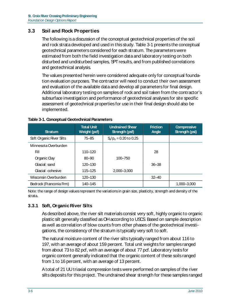
3.3 Soil and Rock Properties
The following is a discussion of the conceptual geotechnical properties of the soiland rock strata developed and used in this study. Table 3-1 presents the conceptualgeotechnical parameters considered for each stratum. The parameters wereestimated from both the field investigation data and laboratory testing on bothdisturbed and undisturbed samples, SPT results, and from published correlationsand geotechnical analysis.
The values presented herein were considered adequate only for conceptual founda-tion evaluation purposes. The contractor will need to conduct their own assessmentand evaluation of the available data and develop all parameters for final design.Additional laboratory testing on samples of rock and soil taken from the contractor’ssubsurface investigation and performance of geotechnical analyses for site specificassessment of geotechnical properties for use in their final design should also beimplemented.
Table 3-1. Conceptual Geotechnical Parameters
StratumTotal Unit
Weight (pcf)Undrained Shear
Strength (psf)FrictionAngle
CompressiveStrength (psi)
Soft Organic River Silts 75–85 Su/po = 0.20 to 0.25
Minnesota Overburden
Fill 110–120 28
Organic Clay 80–90 100–750
Glacial: sand 120–130 36–38
Glacial: cohesive 115–125 2,000–3,000
Wisconsin Overburden 120–130 32–40
Bedrock (Franconia Frm) 140–145 1,000–3,000
Note: the range of design values represent the variations in grain size, plasticity, strength and density of thestrata.
3.3.1 Soft, Organic River Silts
As described above, the river silt materials consist very soft, highly organic to organicplastic silt generally classified as OH according to USCS. Based on sample descriptionas well as correlation of blow counts from other phases of the geotechnical investi-gations, the consistency of the stratum is typically very soft to soft.
The natural moisture content of the river silts typically ranged from about 116 to197, with an average of about 159 percent. Total unit weights for samples rangedfrom about 73 to 82 pcf, with an average of about 77 pcf. Laboratory tests fororganic content generally indicated that the organic content of these soils rangedfrom 1 to 16 percent, with an average of 13 percent.
A total of 21 UU triaxial compression tests were performed on samples of the riversilts deposits for this project. The undrained shear strength for these samples ranged

St. Croix River Crossing Preliminary EngineeringFoundation Design Options Report
June 2010 3-7
from about 30 to 270 psf, with an average of about 105 psf. The undrainedconditions, i.e. =0°, will govern the behavior of this material. The laboratorystrength testing results indicated that Su/po ratios for the soft, organic river siltsranged from about 0.06 to 0.49, with an average of approximately 0.20. Based onthese data and empirical correlations between index properties and shear strength,it is estimated that the Su/po ratio for these soils range from about 0.20 to 0.25.
3.3.2 Minnesota Overburden
The Minnesota overburden materials primarily consist of glacial deposits withinterbedded layers of sand, silt, and clay materials with layers of fill materials,organic loam and fibrous peat. The Minnesota overburden materials are generallyglacially deposited materials which can be classified as SP, SM, ML, and CL. Alsoencountered within the Minnesota overburden materials are pockets and layers oforganic loam and fibrous peat which can be classified as OL. The overburden mate-rials are generally medium dense to very dense or very stiff to hard in consistencybased on SPT N-values as discussed in Section 3.2.2.
The Minnesota overburden materials encountered during the subsurface investiga-tions appear to be extremely variable between borings. The boring data indicatesthat the thickness, consistency, and material type including fill materials and layersof organic material vary considerably. For the purposes of this conceptual study,design parameters of the various material types encountered within the Minnesotaoverburden material were developed. Due to the limited information and testingresults from these materials, the design strength parameters were typically develop-ed based on empirical correlations to SPT N-values. This procedure is commonlyperformed for non-cohesive materials; however, it is generally not as accurate forpredicting the strength parameters of cohesive materials, as with the ML, CL and OLmaterials encountered within the overburden. Typical procedures for determiningthe design parameters for cohesive materials, such a laboratory triaxial testing, werenot available for this conceptual study. Therefore, SPT N-values and other empiricalcorrelations were used for predicting the strength parameters of the cohesivematerials.
Conceptual geotechnical design parameters developed for these soils for this studyare presented in Table 3-1.
3.3.3 Wisconsin Overburden
The Wisconsin overburden materials primarily consist of sands and gravels withvarying amounts of silt and can generally be classified as SP, SM, and GP. Asdiscussed above, occasional layers of slightly plastic silt loam, silt, organic silt, andsilty clay loam materials were observed in this deposit in some of the borings.
The stratum is generally medium dense to very dense in consistency based on SPTN-values as discussed in Section 3.2.3. The layers of fine-grained material aregenerally hard in consistency based on SPT N-values.
St. Croix River Crossing Preliminary EngineeringFoundation Design Options Report
3-8 June 2010
The boring data indicates that layers of non-plastic to slightly plastic silt loam, silt,organic silt, and silty clay loam materials occur within this stratum. These layerswhen encountered were generally classified as ML, CL, and OL according to theUSCS. However, these layers are discontinuous over the site and are not thepredominant soil type within the Wisconsin overburden material. Therefore, geo-technical properties for these fine grained layers were not identified separately forthis conceptual study. The granular deposits which are these main soil types in thiszone will control the behavior of this material. Therefore, for the purpose of thisstudy the Wisconsin overburden was modeled as granular soils in these conceptualanalyses.
Conceptual geotechnical design parameters developed for these soils for this studyare presented in Table 3-1. The geotechnical design parameters are based on SPTN-values and empirical correlations.
3.3.4 Bedrock
Bedrock was encountered at varying depths across the profile of the bridge align-ment except, as described above, at the furthest east portions of the project. TheJordan Sandstone appears on a limited portion of the project which is onshore onthe Minnesota side. Underlying the Jordan Sandstone is the St. Lawrence Formation.This formation appears onshore on the Minnesota portion of the project and brieflyoffshore near the Minnesota shoreline. Underlying the St. Lawrence Formation is theFranconia Formation.
RQD of all the core samples ranged between 0 and 99 percent, with an average of35 percent. However, rock quality varied between the different formations asdiscussed below. Rock strength also varied with rock type and ranged from 187 to10,268 psi for the 70 samples tested during Phases 3 and 4 of the geotechnicalinvestigations as described in Section 2. Figures 7 and 8 depict RQD vs. Elevation andUnconfined Compressive Strength vs. Elevation, respectively, based on bedrockFormation and Member type encountered and/or tested within the subsurfaceinvestigations during these two phases. The variation of rock quality and strengthshould be considered in the design of the foundations for the bridge structures.
A total of only approximately 30 feet of Jordan Sandstone was cored during thesubsurface investigations with a core recovery ranging from 62 to 100 percent, withan average of 82 percent, and an RQD ranging from 0 to 85 percent, with an averageof about 40 percent. Only 6 unconfined compressive strength tests were performedon the Jordan Sandstone with compressive strengths ranging from 584 to 5,536 psi.The mean strength of 2,396 psi is indicative of weak rock. The limited number ofcoring and testing is indicative of the limited extent of the Jordan Sandstone presentthroughout the project location.
Recovery of the rock cores from the St. Lawrence Formation provided a range from51 to 100 percent, with an average of 93 percent. RQD of the rock cores from the St.Lawrence Formation ranged from 0 to 83 percent and an average of 55 percent. A

St. Croix River Crossing Preliminary EngineeringFoundation Design Options Report
June 2010 3-9
total of 12 samples of the St. Lawrence Formation were strength tested. All 12samples were of the Lodi Member. The results indicate weak to very strong rockwith a range from 1,950 to 10,268 psi. The mean strength was 6,215 psi.
Rock cores from the Franconia Formation had core recovery values ranging from 0 to100 percent, with an average of 84 percent, and RQD values ranging from 0 to99 percent with an average of approximately 35 percent. A total of 51 samples ofthe Franconia Formation were tested. The results indicate very weak to strong rockwith a range from 187 to 8,942 psi and a mean strength of 1,843 psi.
Based on the boring logs and as described in the aforementioned Memorandumfrom Mn/DOT dated August 4, 2006, in the project area, the Franconia Formationconsists of four members. The uppermost member, the Reno Member, had recoveryvalues ranging from 10 to 100 percent, with an average of 89 percent, and RQDvalues ranging from 0 to 99 percent, with an average of 41 percent. A total of 38 ofthe 51 strength tests within the Franconia Formation were performed on cores fromthe Reno Member. The results on the Reno Member indicate very weak to verystrong rock with a range from 499 to 8,942 psi and a mean strength of 2,201 psi. TheReno Member is well cemented in most zones but does contain small areas where itis soft.
Within the Mazomanie, the next Member encountered within the borings, recoveryvalues ranged from 0 to 100 percent with an average of 66 percent, and RQD valuesranged from 0 to 69 percent, with an average of 20 percent. A total of 10 sampleswere tested with strengths ranging from 187 to 1,490 psi and average of 637 psi,indicating very weak to weak rock. As described in the Memorandum from Mn/DOT,the Mazomanie is mainly poorly cemented and friable, thus contributing to lowerstrength test results than the other members.
Recovery values from the rock coring of the Tomah Member, the third Member ofthe Franconia Formation encountered within the borings, ranged from 59 to 100percent, with an average of 95 percent. RQD values ranged from 0 to 68 percent,with an average of 26 percent. A total of 3 strength tests were performed on theTomah Member. The results indicate weak rock with a range from 980 to 2,100 psiand a mean strength of 1,567 psi.
The basal member of the Franconia Formation is the Birkmose which consists ofinterbedded fine-grained sandstone and siltstone as well as glauconitic sandstone.Core recovery values from the Birkmose Member ranged from 92 to 100 percent,with an average of 98 percent, and RQD values ranged from 33 to 98 percent, withan average of 57 percent. No unconfined compressive strength tests wereperformed within the Birkmose Member.
As described in Section 4, the bridge pier locations with higher foundation loaddemands will have foundations which penetrate into bedrock, i.e., drilled shaftssocketed into bedrock. Based on the available subsurface information, thefoundations at these pier locations will generally be founded in the Franconia

St. Croix River Crossing Preliminary EngineeringFoundation Design Options Report
3-10 June 2010
Formation. That is, the two upper formations, the Jordan Sandstone and St.Lawrence Formation, are of limited extent along the bridge alignment and aretypically not encountered at the foundation locations. Therefore, the bedrockproperties used for this conceptual evaluation were based solely on the FranconiaFormation.
3.4 Groundwater Conditions
Groundwater observations made in the test borings were used to estimate thegroundwater level for the conceptual analyses. The data indicate that the ground-water elevation at the time of the investigation generally varied depending on thetopography of the site. Borings drilled near the St. Croix River encountered ground-water close to the elevation of the existing river level. Borings drilled on land and athigher elevations typically encountered groundwater at higher elevations than thosecloser to the river. Normal pool levels of the St. Croix River were taken as Elevation680 for the purposes of this study.
Onshore on the Minnesota side, the borings indicated groundwater levels betweenapproximately 32.5 and 11.5 feet below the ground surface from approximateStations 440+00 to 450+00 along the mainline. These depths correspond to anelevation of just under 700 feet. At stations greater than 450+00, closer to the river,the groundwater gradually lowers to an elevation of the river itself which isapproximately 683 feet +/-.
Onshore on the Wisconsin side, groundwater readings were not recorded within theborings taken during 2005 or 2009. However, based on previous investigations, thegroundwater elevation appears to gradually increase further away from the river. Inborings taken approximately 300 feet from the shoreline, the groundwater level wasrecorded to be approximately 61 feet below the ground surface which correspond toa similar elevation as the river. However, at borings taken approximately 500 feetfrom the shoreline (similar to the distance of the east abutment located from theshoreline), the groundwater elevation was recorded at approximately 56 feet belowthe ground surface which corresponded to approximately El. 723 feet.
Artesian groundwater conditions were observed at three locations (borings T-203,T-210 and T-211) during drilling operations. Boring T-211 is located at the Minnesotashoreline, and borings T-203 and T-210 are located in the St. Croix River. In BoringT-203, at an elevation of El. 485 feet artesian conditions were observed within theBirkmose Member of the Franconia Formation. Boring T-210 encountered anartesian condition at El. 580 feet within the Reno Member of the Franconia Forma-tion. And lastly, in Boring T-211, at El. 599 feet low flow, artesian conditions wereobserved within the Reno Member. Artesian heads were not recorded during theinvestigation. Only flow rates were provided on the boring logs. The flow ratesranged from about 1 qt/min to approximately 5 gal/min and are presented on theMn/DOT boring logs when encountered.

St. Croix River Crossing Preliminary EngineeringFoundation Design Options Report
June 2010 3-11
Water level readings have been made in drill holes at times and under conditionsstated in the boring logs. These data have been reviewed and interpretations madein the text of this report. However, it must be noted that fluctuations in the level ofthe groundwater may occur due to variations in season, rainfall, temperature, andother factors not evident at the time measurements were made and reportedherein.


St. Croix River Crossing Preliminary EngineeringFoundation Design Options Report
June 2010 4-1
4 Foundation Design Options
4.1 General
The proposed St. Croix River Crossing is comprised of three separate bridges that areidentified as Mn/DOT Bridge Nos. 82045, 82047, and 82048. Bridge No. 82045(Mainline TH 36 and STH 64) spans Minnesota TH 95, the onshore Minnesota side,the St. Croix River, and the onshore Wisconsin side. Its west abutment is locatedimmediately west of TH 95 and its east abutment is located on the Wisconsin side ofthe river. Bridge No. 82047 (TH 36WB off-ramp to TH 95) and Bridge No. 82048(TH 36EB on-ramp from TH 95) both span a portion of the onshore Minnesota side.Bridges 82047 and 82048 have a concrete box girder superstructure that frames intoan approach span of Bridge 82045.
For the purpose of this study, and to facilitate discussion of feasible foundationtypes, the geotechnical and foundation option assessment has been divided intothree separate “project areas” for the three bridges. They are: 1) onshore on theMinnesota side; 2) within the St. Croix River; and, 3) onshore on the Wisconsin side.Onshore on the Minnesota side, the three approach bridges are similar in nature inthat they have a concrete box girder superstructure and the general loading andsubsurface conditions are anticipated to be somewhat similar. Within the river, thebridge spans consist of an extradosed superstructure that combines concrete boxgirders with cable stays. Onshore on the Wisconsin side, the spans have an extra-dosed superstructure as well, except the subsurface conditions vary from theconditions anticipated at the river spans.
The main geotechnical issues for the conceptual design of the bridges include:Identify feasible foundation types for each structure based on factors such asdesign requirements, constructability, subsurface conditions and cost.Performance of concept level axial static and deformation analyses of theidentified foundation alternative for each structure to estimate vertical capacityand penetration requirements to support bridge loads.Assess lateral load capacity and displacement characteristics of the selectedfoundation alternative for each structure and subsurface conditions.
The following is a discussion of the conceptual foundation evaluations and recom-mendations. The discussion includes the descriptions of three “project areas” asmentioned above and assumes that the foundation type for each of the structureswill generally be similar within these locations.
4.2 Minnesota Onshore Spans
The area described as the Minnesota Onshore Spans includes the abutments andpiers located on the Minnesota side of the river for all three bridges for the project.The spans along Bridge Nos. 82047 (TH 36WB off-ramp to TH 95) and 82048(TH 36EB on-ramp from TH 95) are included within the Minnesota Onshore Spans aswell as the superstructure spans of the mainline, Bridge No. 82045 (Mainline TH 36

St. Croix River Crossing Preliminary EngineeringFoundation Design Options Report
4-2 June 2010
and STH 64), which are located onshore on the Minnesota side. These include thewest abutment and Pier Nos. 1 through 7 of the mainline as indicated on Figures 1and 3. Refer to Figure Nos. 5 and 6 for Bridges 82047 and 82048, respectively.
Foundations for support of the Minnesota onshore spans were evaluated consider-ing the subsurface conditions, estimated design loads, estimated settlements andlateral deformations, and constructability with respect to existing site conditions.Cost of the foundation is also considered.
Spread footings are not suitable for support of the new bridge piers and abutmentsbased on the preliminary subsurface information and anticipated loads. Someborings within the Minnesota onshore spans encountered variable thicknesses ofsoft, organic clays. These materials were typically encountered within the wetlandareas near the St. Croix River. Also encountered were variable thicknesses ofuncontrolled fill likely present from previous construction activity in the area. Bothof these material types are generally considered unsuitable for shallow foundationsupport. Accordingly, foundations for the Minnesota onshore spans will need to besupported on deep foundations.
Considering that bedrock is within a reasonable depth to provide a bearing layer andbased on the limited subsurface information of the Minnesota Overburden Materialsavailable at this time, it is concluded that for the purposes of this study the deepfoundations will terminate on or in the bedrock. The depth to bedrock within theMinnesota onshore spans varies between pier locations, but the existing subsurfaceinformation generally indicates the bedrock is 25 to 55 feet below the groundsurface. Two potential foundation options considered for the Minnesota OnshoreSpans are drilled shafts socketed into bedrock and piles driven to refusal on bedrock.Both foundation types are considered feasible.
Drilled shafts would likely be constructed by the cased method of construction usingtemporary or permanent casing. The casing would extend to the top of the bedrock.Due to the anticipated seepage from the weathered and fractured rock zones as wellas the possible artesian conditions, construction of the rock socket will require tech-niques to control the potential seepage and possibly artesian conditions. Artesianconditions were not reported at any of the land borings conducted during thesubsurface investigations, however the contractor should investigate the potentialfor artesian conditions and consider them during final design.
The rock socket length would be estimated based on laboratory strength test resultsof rock samples as well from information gained from load testing of drilled shaftsperformed by the contractor. Based on the conceptual analysis conducted for thisstudy, however, the construction of the drilled shaft groups required to resist theloading conditions of the Minnesota onshore spans may produce greaterenvironmental impacts than driven piles. In an effort to reduce the environmentalimpacts to adjacent wetlands, only driven piles were considered for the Minnesotaonshore spans for the purposes of this conceptual evaluation.

St. Croix River Crossing Preliminary EngineeringFoundation Design Options Report
June 2010 4-3
Several pile types would be feasible for the foundations of the Minnesota approachstructures including steel pipe piles and H-piles. Steel H-piles are well suited fordriving through dense soil, gravel and cobble layers which could be encountered atrelatively shallow depths within the Minnesota Overburden Materials. Furthermore,the H-piles have the significant advantage that when fitted with a hardened drivingtip, they penetrate obstructions and are less susceptible to damage when driven torock. Steel pipe piles, on the other hand, are more susceptible to damage duringhard driving conditions than H-piles. For this reason, and given the subsurface con-ditions within the Minnesota Overburden Materials, steel H-piles were consideredbecause of their ability to achieve a relatively high capacity when driven to bedrockalong with good drivability characteristics.
H-piles will develop their axial compressive capacity from end bearing on rock anduplift capacity from frictional resistance in the overburden soils. As discussed inSection 3, the borings drilled at the site indicate that at some locations, the upperzone of the rock at the site is highly fractured and has low RQD values; therefore,the geotechnical capacity of the piles should be verified with static load tests. Inaccordance with AASHTO LRFD Bridge Design Specifications, the design capacity forsteel piles driven to refusal on rock is controlled by the structural capacity of the pilewith due consideration being given for drivability and constructability issues. If it isconcluded that the pile cannot be driven to bedrock without inducing excessivedriving stresses or if there is a risk of pile damage during driving, reduced capacitiesshould be utilized for design.
Different sizes of piles were considered at this time since the final loads are notavailable. The final selection of the section should be made by the contractor’sengineer based on the results of their analyses, load requirements and cost.However, it is our opinion that the larger HP sections are preferred due to theirhigher load capacity and better driving characteristics.
It is anticipated that the applied lateral loads will be resisted by battered piles, usinga maximum batter of 4 vertical:1 horizontal. However, only vertical piles can be usedif a more flexible foundation is desired for selected loading considerations. Atlocations where vertical piles are used, lateral pile analyses must be performed forthe final pile layout and loads when the pile group configurations and loads arefinalized.
For low-displacement steel H-piles, the center-to-center spacing of the piles shouldnot be less than three times the width of the pile at the bearing level. Since the pilesrely on frictional resistance in the soil overburden to resist tension loads, the center-to-center pile spacing should not be less than three times the pile width unlessgroup reduction effects are evaluated. Where piles are battered, the tops of thepiles can be as close as two pile widths, provided the preceding requirement issatisfied. The steel piles should be provided with hardened steel tip reinforcementto protect the piles from damage when driving to rock.

St. Croix River Crossing Preliminary EngineeringFoundation Design Options Report
4-4 June 2010
The conceptual level analyses performed as part of this study included both lateraland axial load analyses for the H-piles located at foundations within the Minnesotaonshore spans. Generalized profiles based on the existing boring information andthe subsurface profiles developed for this report and used for the analyses wereconsistent to those observed at Pier Nos. 2, 4 and 6 of Bridge No. 82045 (MainlineTH 36 and STH 64). The profiles consisted of Minnesota overburden materialsextending to a depth of 32, 26, and 22 feet below the bottom of the proposed pilecap for Pier No. 2, 4, and 6, respectively, underlain by bedrock.
It was assumed that the pile groups would be driven to refusal at the top of thebedrock surface and, as such, the axial capacity of a single pile was estimated usingthe factored axial structural capacities as described above with consideration fordrivability and potential pile damage during driving. For estimating the axial tensilecapacity (uplift), frictional resistance from the Minnesota overburden materials wasconsidered.
Pile groups were analyzed using the GROUP v. 7.0 computer program by Ensoft, Inc.The lateral response of the piles in the soil was modeled using a non-linear soilreaction versus lateral displacement relationship represented by p-y curves. The p-ycurves were internally generated by the computer programs for the various soildeposits within the generalized profile of the Minnesota onshore spans.
The lateral load analysis considered the combined vertical and horizontal loadsapplied to the pile group. The most critical load condition for each pier location asprovided by the project structural engineers was used for the analyses. The internalforces and bending moments in the piles were compared to the maximum factoredaxial load and bending moment capacities for the H-piles.
Conceptual pile configurations were developed by limiting the axial force per pile tothe factored axial capacity, maintaining the internal forces and bending moments inthe piles to less than the maximum factored capacities of the piles, and limiting thelateral and axial settlements to less than the tolerable settlements developed by theproject structural engineers.
4.3 St. Croix River Spans
The area described as the St. Croix River Spans includes those pier locations of themainline, Bridge No. 82045 (Mainline TH 36 and STH 64), which are located withinthe river itself. These include Pier Nos. 8 through 13 as indicated on Figure 4.
Foundations for support of the mainline river spans were evaluated considering thesubsurface conditions, estimated design loads, estimated settlements and lateraldeflections, and constructability with respect to existing site conditions. Cost of thefoundation is also considered.
Spread footings are not suitable for support of the new bridge piers and abutmentsdue to the risk of scour and the presence of deep, soft organic river silts.

St. Croix River Crossing Preliminary EngineeringFoundation Design Options Report
June 2010 4-5
Accordingly, foundations for the river spans will need to be supported on deepfoundations. Considering that bedrock is within a reasonable depth to provide endbearing resistance and soils overlying the bedrock will not provide significantresistance, the deep foundations will need to terminate on or in the bedrock. Twopotential foundation schemes, considering the existing subsurface conditions andthe extremely large loads at each pier location, are large diameter pipe piles drivento refusal or drilled shafts socketed into bedrock. The soft, organic river silts typicalat the river pier location cannot adequately resist the lateral loading demands.Furthermore, the dense sand and gravel of the Minnesota and Wisconsin overbur-den materials are not present at Pier 10 and only range from approximately 10 to35 feet at Piers 8, 9, 11, and 12 which is not adequate to resist the anticipatedfoundation loads. Although a scour analysis was not performed for this conceptualevaluation, these materials are susceptible to scour and cannot be relied upon forresistance of the loading conditions. Therefore, given the limited thickness ofoverburden material which cannot adequately resist the large lateral shear andbending moments, it is recommended to extend the foundation into the bedrock inorder to meet the lateral and axial loading requirements. For this reason, theconceptual foundation recommended for the St. Croix River Spans are drilled shaftssocketed into rock.
It should be noted that it may be possible for large diameter pipe piles to adequatelyresist the axial loads as well as shear and bending moments at Pier 13. The subsur-face conditions at this pier consist of approximately 40 feet of soft, organic river siltsunderlain by approximately 60 feet of the dense Wisconsin overburden material.However, it may not be practical nor economical to mobilize the large pile drivingequipment needed to drive the large diameter pipe piles for only one of the six pierswhich encompass the River Spans. In addition, the flexibility and load responsebehavior of the driven pile foundation appears to be significantly different than thedrilled shafts needed for the other piers. Therefore, for the purposes of this report,it was assumed that drilled shafts would be utilized at this location as well.
PB performed conceptual geotechnical analyses as part of this Foundation DesignOption Report. These analyses included both lateral and axial load analyses for thedrilled shafts located at piers within the River Spans. Generalized profiles weredeveloped for the River Spans based on the existing boring information and wasused for the geotechnical analyses. The generalized profiles used for the analyseswere similar in nature to those observed at Pier Nos. 8, 10 and 12. The profile at Pier8 included 8 feet of the Minnesota overburden material, underlain by bedrock. Theprofile at Pier 10 included 70 feet of soft, organic river silts underlain by bedrock.The profile at Pier 12 included 55 feet of soft, organic river silts, underlain by 30 feetof the Wisconsin overburden material, underlain by bedrock.
The lateral load capacity of a single shaft was evaluated using the computer programLPILE Plus v. 5.0 by Ensoft, Inc. of Austin, TX. Shaft groups were analyzed using theGROUP v. 7.0 computer program by Ensoft, Inc. The lateral response of the shafts inthe soil was modeled using a non-linear soil reaction versus lateral displacement

St. Croix River Crossing Preliminary EngineeringFoundation Design Options Report
4-6 June 2010
relationship represented by p-y curves. The p-y curves, as well as group reductionfactors, were internally generated by the computer programs for the various soildeposits within the generalized profile of the River Spans given the subsurfaceconditions and group spacing and size.
The lateral load analysis considered the combined vertical and horizontal loadsapplied to the shaft group. The most critical load condition as provided by theproject structural engineers was used for the analyses. The internal forces andbending moments in the drilled shafts were compared to the maximum allowableaxial load and bending moment combinations for the shafts using the interactiondrawings as provided by the project structural engineers.
The axial load capacity for the dimensions of the drilled shafts which satisfied theloading and lateral displacement criteria were performed using the methodsrecommended in AASHTO LRFD Bridge Design Specifications (2007) as well as takinginto consideration the results of the load test performed by Mn/DOT in 1995 assummarized by O’Neill and Majano (January 1996). These analyses were performedto determine the penetration requirements for the highest loaded shaft(s) in eachgroup as determined by the GROUP analyses. Considering the relatively lowfrictional resistance of the river silts material and the relatively thin, discontinuouslayer of either the Wisconsin or Minnesota overburden material, the axial capacityof the shafts was assumed to result from the frictional and end bearing resistance ofthe rock sockets.
Using the procedures as outlined in AASHTO LRFD Bridge Design Specifications(2007), the required rock socket length-to-diameter (L/D) ratios were determined tobe relatively high. Generally, high L/D ratios result in limited load transfer to theshaft tip based on strain compatibility issues. It was determined to include thecalculated end bearing resistance in the determination of the nominal axial capacityof the drilled shaft and to address the strain compatibility by the use of a lowerresistance factor for end bearing than for side resistance.
For the purposes of this conceptual analysis it was assumed that the drilled shaftswill be constructed by the cased method of construction using permanent casing.The permanent casing was assumed to extend to the top of the bedrock. It was alsoassumed that, due to the anticipated seepage from the weathered and fracturedrock zones as well as the observed artesian conditions during the subsurfaceinvestigations, construction of the rock socket will require wet excavation methodswith a positive head greater than those of the artesian pressures or other tech-niques to control the potential seepage and artesian conditions. It is critical for thecontractor to fully evaluate the magnitude of the artesian pressures and determinean accurate estimate of the artesian pressure and consider this condition duringfinal design.

St. Croix River Crossing Preliminary EngineeringFoundation Design Options Report
June 2010 4-7
To determine the conceptual rock socket penetration requirements the followingcriteria were used:
A permanent casing will be installed to the top of bedrock and 1 percent steelreinforcement in the drilled shaft.A resistance factor of 0.60 and 0.55 were used for the side resistance and endbearing, respectively. The resistance factors were based on the recommenda-tions as specified in AASHTO LRFD Bridge Design Specifications (2007).The maximum uniform nominal side friction for the rock socket was estimated tobe 6.7 ksf for the first 30 feet of rock socket length and 7.9 ksf for any additionalsocket length. These values were based on the average value of those asdetermined by the using the methods recommended in AASHTO LRFD BridgeDesign Specifications (2007) and those observed during the load test performedby Mn/DOT in 1995 as summarized by O’Neill and Majano (January 1996).Uplift capacity of the shaft was assumed to be 70 percent of the socket sidefriction.The end bearing of the rock socket was estimated to be 19.2 ksf assuming aminimum rock socket penetration of 30 feet. It was determined that the valueobtained by using the methods recommended in AASHTO LRFD Bridge DesignSpecifications (2007) was conservative based on the load test data presented inthe O’Neill and Majano report. Therefore, the above value was based on therecommendations of the load test performed as summarized by O’Neill andMajano (January 1996) alone.The rock socket diameter was assumed to be 1 foot smaller than the casingdiameter in soil.Center to center shaft spacing for all group arrangements was assumed to bethree times the shaft diameter in the longitudinal direction (parallel to the bridgecenterline) and 2.5 times the diameter in the transverse direction (perpendicularto the bridge centerline). The greater spacing in the longitudinal direction wasconsidered to satisfy the greater lateral loading conditions in the longitudinaldirection.Rock socket L/D ratios were relatively high which will result in limited loadtransfer to the shaft tip.
Based on the above analyses, it is estimated that 10 foot diameter drilled shafts witha 9-foot diameter rock socket, ranging in penetration depths from 50 to 55 feet intobedrock, would have a factored axial resistance of approximately 6,800 to7,500 thousand pounds (kips). Based on the service loads currently provided by thestructural engineers, predicted settlements were estimated to be less than 0.50 –inch and lateral displacements were estimated to be less than 0.25 inch for the10-foot diameter shaft with a 9-foot diameter rock socket.
4.4 Wisconsin Onshore Spans
The area described as the Wisconsin Onshore Spans includes those pier locations ofthe mainline, Bridge No. 82045 (Mainline TH 36 and STH 64), which are located on

St. Croix River Crossing Preliminary EngineeringFoundation Design Options Report
4-8 June 2010
the Wisconsin shoreline. These are Pier No. 14 and the East Abutment as indicatedon Figure 4.
Foundations for support of the Wisconsin onshore spans were evaluated consideringthe subsurface conditions, estimated design loads, estimated settlement and lateraldeflection, and constructability with respect to existing site conditions. Cost of thefoundation is also considered.
The subsurface conditions at the Wisconsin Onshore Spans consist of thick depositsof the typically dense, Wisconsin overburden materials overlying bedrock which aregenerally considered acceptable for shallow foundations. However, the anticipatedloading from the spans would require large footing sizes which could result inunacceptable settlements. Therefore, for the purposes of this conceptual evaluation,spread footings were not considered suitable for support of the new bridge piersand abutments based on anticipated loads and the subsurface conditions. Accord-ingly, foundations for the Wisconsin onshore spans will need to be supported ondeep foundations. Two potential foundation options considered for the WisconsinOnshore Spans are drilled shafts or driven piles. Both foundation types areconsidered feasible.
4.4.1 Drilled Shafts
The methods and procedures outlined within Section 4.3: St. Croix River Spans wereused to analyze the drilled shafts for the Wisconsin spans. The lateral load capacityof a single shaft was evaluated using the computer program LPILE Plus v. 5.0 byEnsoft, Inc. of Austin, TX. Shaft groups were analyzed using the GROUP v. 7.0computer program by Ensoft, Inc. The axial load capacity for the dimensions of thedrilled shafts were performed using the methods recommended in AASHTO LRFDBridge Design Specifications (2007) as well as using the recommendations aspresented in the FHWA manual Drilled Shafts: Construction Procedures and DesignMethods (1999). These analyses were performed to determine the penetrationrequirements for the highest loaded shaft(s) in each group as determined by theGROUP analyses.
Drilled shafts would likely be constructed by either the cased method of construc-tion using temporary casing or by the wet method of construction using a temporarystarter casing and drilling fluid such as mineral or polymer slurry to maintain thestability of the hole. Given the subsurface information, methods should be taken tomaintain the stability of the excavation for each shaft in order to prevent sloughingor collapsing of the sidewalls during construction. For the conditions encountered atthe Wisconsin onshore spans, it appears that the required capacity of a single drilledshaft could be achieved without socketing the drilled shafts into the bedrock locateddeep below the ground surface.

St. Croix River Crossing Preliminary EngineeringFoundation Design Options Report
June 2010 4-9
To determine the required conceptual penetration requirements the followingcriteria were used:
The shafts were assumed to be installed by the temporary casing method or atemporary starter casing method with the wet method of construction witheither mineral or polymer slurry used to maintain the stability of the hole.1 percent steel reinforcement in the shaft.Resistance factors of 0.55 and 0.50 were used for the side resistance and endbearing, respectively, for the Wisconsin overburden material. The resistancefactors were based on the recommendations as specified in AASHTO LRFD BridgeDesign Specifications (2007). The Pier 14 location resistance factors of 0.60 and0.55 were used for side resistance and end bearing, respectively, withconsideration for increased redundancy.Uplift capacity of the shaft was assumed to be 70 percent of the drilled shaft sidefriction for conceptual evaluations.Center to center shaft spacing for all group arrangements was assumed to bethree times the shaft diameter.
Based on the above conceptual analyses, it is estimated that 10 foot diameter drilledshafts ranging in penetration depths from 100 to 110 feet into the Wisconsinoverburden materials at the Pier 14 location, would have a factored axial resistanceof approximately 7,400 to 8,400 kips. Based on the service loads currently providedby the structural engineers, predicted settlements were estimated to be less than0.50 –inch and lateral displacements were estimated to be less than 0.25 inch forthe 10-foot diameter shafts with 1 percent reinforcement. .
For the east abutment, the loads currently provided by the structural engineers areconsiderably less than at Pier 14. Therefore, it is estimated that 8-foot diameterdrilled shafts ranging in penetration depths from 40 to 50 feet into the Wisconsinoverburden materials, would have a factored axial resistance of approximately 2,400to 3,000 kips.
4.4.2 Steel Piles
Large diameter driven pipe piles were also considered for support of the Wisconsinonshore spans. 42-inch diameter piles with 1-inch wall thickness were considered forPier 14. The use of smaller diameter piles were considered, however, due to thelarge load demands at pier 14, the number of smaller-diameter piles becameexcessive and therefore the smaller diameter piles were not considered a viableoption for this conceptual evaluation. At the east abutment, where the loadingdemands are less, 24-inch diameter piles with a 5/8-inch wall thickness wereconsidered feasible. In both cases, the piles were assumed to be driven open-ended.The center-to-center spacing of the piles should not be less than three times thewidth of the pile at the bearing level. In addition, it was assumed that the pipe pileswould plug during driving. Wave Equation Analyses (WEA) were also performed todetermine if the piles could be driven to depth without exceeding the allowabledriving stresses in the pile as discussed below.

St. Croix River Crossing Preliminary EngineeringFoundation Design Options Report
4-10 June 2010
The conceptual level analyses performed as part of this study included both lateraland axial load analyses for the pipe piles located at Pier 14 and the east abutment.Generalized subsurface profiles for each location were based on the existing boringinformation and the subsurface profiles developed for this report.
As with the drilled shaft analysis performed for the Wisconsin onshore spans, pilegroups were analyzed using the GROUP v. 7.0 computer program by Ensoft, Inc. Thelateral load analysis considered the combined vertical and horizontal loads appliedto the to the pile group. The most critical load condition for each pier location asprovided by the project structural engineers was used for the analyses. The internalforces and bending moments in the piles were compared to the maximum factoredaxial load and bending moment resistances for the pipe piles.
The axial load resistances were determined using the methods recommended inAASHTO LRFD Bridge Design Specifications (2007) as well as using the recommenda-tions as presented in the FHWA manual Design and Construction of Driven PileFoundations, Volumes I and II (2006). These analyses were performed to determinethe penetration requirements for the highest loaded pile(s) in each group asdetermined by the GROUP analyses.
Conceptual pile configurations were developed by limiting the axial force per pile tothe factored axial resistance, maintaining the internal forces and bending momentsin the piles to less than the factored resistance of the piles, and with considerationto lateral displacements and axial settlements.
For the purposes of this conceptual evaluation, drivability analyses (Wave EquationAnalyses [WEA]) using the computer program GRLWEAP have been performed toevaluate if it feasible to drive the recommended piles to the required nominalresistances without overstressing the piles. For piles driven in hard driving condi-tions, damage to the piles during driving can occur if driving stresses exceed theallowable pile stress. Conversely, some hammers are incapable of providing theenergy required to achieve the required nominal resistance. For the given subsur-face conditions and assuming a typical hammer and driving system which may beavailable, the preliminary drivability study indicates the piles analyzed should beable to be driven to the required resistances without overstressing the piles.
It should be noted that the drivability study performed herein was performed withone hammer system operating with typical performance specifications for each piletype analyzed. A wide range of hammer systems are available and thereforeadditional WEA analyses should be performed by the contractor during final designusing the actual driving system proposed for construction . The approval of thecontractor’s driving system should be made based on the results of a WEA anddynamic pile analyses, as indicated in Section 5.0.
Based on the above conceptual analyses, it is estimated that at Pier 14, the 42-inchdiameter pipe piles ranging in penetration depths from 100 to 115 feet into theWisconsin overburden materials would have a factored axial resistance of

St. Croix River Crossing Preliminary EngineeringFoundation Design Options Report
June 2010 4-11
approximately 1,500 to 2,400 kips. The factored resistances were based on aresistance factor of 0.5 based on the recommendations as specified in AASHTO LRFDBridge Design Specifications (2007). Based on the service loads currently provided bythe structural engineers, predicted settlements and lateral deflections of the 42-inchdiameter piles were estimated to be less than 0.25 inch.
At the East Abutment location, 24-inch diameter piles ranging in penetration depthsfrom 40 to 50 feet would have a factored axial resistance of approximately 400 to470 kips. The factored resistances were based on a resistance factor of 0.5 based onthe recommendations as specified in AASHTO LRFD Bridge Design Specifications(2007). Based on the service loads currently provided by the structural engineers,predicted settlements and lateral deflections of the 24-inch diameter piles wereestimated to be less than 0.25 inch.


St. Croix River Crossing Preliminary EngineeringFoundation Design Options Report
June 2010 5-1
5 Future Studies and Analyses
5.1 General Considerations
This section of the report discusses the geotechnical issues related to the design ofthe bridge foundations as well as the geotechnical issues related to the Design-Build(DB) aspect of the contract.
The preliminary data and evaluations presented herein are based on limitedgeotechnical information and analysis and are therefore not adequate for finaldesign or construction purposes. Therefore the selected contractor should berequired to perform all of the additional geotechnical investigations and analysesrequired for the project in accordance with the requirements of the DB criteria andthe request for proposal documents. In all cases the contractor should be requiredto perform all investigations and designs in accordance with the requirements ofMn/DOT, FHWA, and AASHTO standards.
5.2 Deep Foundation Construction Considerations, Testing andMonitoring
It is recommended that the contractor perform field testing and monitoring for alldeep foundation types to evaluate nominal resistances, integrity, verification ofdesign assumption, pile driving performance (if applicable), installation character-istics, and to establish production foundation depths. At a minimum, the foundationtesting and monitoring shall include test piles and monitor piles, and/or test andtechnique drilled shafts; dynamic testing; static testing; non-destructive integritytesting; and quality control testing, as applicable.
For deep foundations, testing is needed to: a) confirm geotechnical resistances andperformance; b) assess the performance of the contractor’s installation procedureand equipment; and c) provide quality control during installation operations for theselected foundation type(s).
5.2.1 Construction and Testing Considerations for Driven Piles
Piles bearing on rock should be driven to refusal to achieve the required compres-sion resistances and to a minimum tip elevation to achieve the required uplift orlateral resistance. Refusal should be defined as 20 blows per inch of driving or whereno measurable net penetration under hammer blows is recorded. Pile hammersshould have a minimum energy to enable piles to be driven to the required nominalresistance without inducing damage to the pile. The location of the nominalresistance should be in the rising portion of the resistance versus blow count curve.The hammer should also not induce driving stresses in the pile in excess of90 percent of the yield point of the steel. If any piles meet refusal above therequired minimum tip elevations, the pile uplift and lateral capacity will have to bereevaluated and additional piles added to the caps, if needed. Therefore, it isimportant that minimum tip elevation requirements be developed by the designerbased on the actual uplift and lateral load requirements for the foundations.

St. Croix River Crossing Preliminary EngineeringFoundation Design Options Report
5-2 June 2010
Wave Equation Analyses
WEA should be performed prior to pile driving operations for the actual drivingsystem proposed by the contractor. The results of the WEA can be used to assessthe suitability of the proposed pile driving equipment, to predict the driving stresses,to develop initial driving criteria, and to determine the required minimum energy tobe transferred to the pile.
Test Piles
Test or index piles should be driven prior to production pile driving operations toassess the driving characteristics, capacity and embedment requirements of thefoundation piles at the various locations along the project alignment. The test pilesshould be located near existing borings and in areas considered representative ofthe project site conditions to facilitate development of correlations between drivingresistance and the subsurface conditions. The actual number and location of the testpiles should be determined after the pile layout for each substructure element isdeveloped.
Dynamic Testing
Dynamic pile testing using a pile-driving analyzer (PDA) should be performed on alltest piles and periodically during production pile driving. Dynamic testing can beused to estimate pile capacity, measure driving stresses in the piles, determine theactual energy transferred to the pile for assessing hammer performance, and toevaluate the integrity of piles suspected of being damaged. In addition to PDA,CAPWAP analysis of the dynamic test data should be performed for all test piles andperiodically during production pile driving operations. Restriking with dynamictesting and CAPWAP analyses should be performed on the test piles.
Static Load Tests
Static load tests are recommended to confirm the nominal resistance of the piles.Load test for compressive resistance of the piles are recommended due to the lowRQD values in the bedrock which indicates poor quality rock and to verify thedynamic pile test results and to verify that the driving equipment can achieve therequired pile capacity.
5.2.2 Construction Considerations for Drilled Shafts:
One of the most important aspects of drilled shaft construction is the method usedto install the shafts. The installation method can influence both the cost andgeotechnical resistance of the shaft. Drilled shaft foundations will require advancingof a drill and casing through very variable ground conditions. Based on the subsur-face conditions at the site, it is anticipated that the drilled shafts in the river and onthe Minnesota approach will be constructed using casing extending to the top ofrock. In the river, permanent casing will be required. It may be possible to usemineral or polymer drilling fluids in place of the casing in some soil deposits butadditional evaluation of this option should be performed as part of the load test

St. Croix River Crossing Preliminary EngineeringFoundation Design Options Report
June 2010 5-3
program currently being planned by Mn/DOT. It is recommended that the contractorbe required to provide equipment that is capable of installing the required casingand stabilizing the excavation at all times.
It is recommended that the drilled shaft test program include technique shafts andload tests on drilled shafts. The load test shafts should be installed using themethods and equipment that successfully install the technique shaft. Techniqueshafts should be installed with the same size and configuration, and in the samesubsurface conditions and within 20 feet of a foundation group it is intended torepresent. It is recommended that load tests be performed using the Osterberg loadcell. In addition, the shafts should be instrumented with strain gages at variousdepths so that the load transfer relationships can be developed for the variousdeposits at the site. This will allow confirmation or modification of the design frictionvalues.
Osterberg load cell (O-cell®) consists of a hydraulically operated load cell cast intothe bottom of the rock socket. As pressure is applied to the load cell it applies anupward load to the shaft and a downward load to the rock beneath the drilled shaftto determine the available friction and end bearing resistance for the rock socket.This type of test eliminates the need for a heavy reaction frame associated withconventional tests where the load is applied to the top to the shaft. For drilled shaftsat the Wisconsin side of the project, the O-cells can be located at a level where thefriction above the O-cells balances the friction and end bearing resistance below theO-cells; if necessary, two levels of O-cells can be used to obtain nominal resistancevalues along the entire length of the drilled shaft.
Instrumentation typically used for an Osterberg load tests include:LVDT gages to monitor O-cell expansion.Vibrating wire strain gages embedded in the shaft to determine stresses atvarious levels in the shaft, and to allow calculation of unit friction (bond)resistance along the sides of the rock socket.Telltales embedded within the shaft and at the top of the O-cell to monitor shaftdisplacement.Dial gages and piano wire gage to monitor displacement of the top of shaft.Readings of the top of shaft displacements using optical survey equipment.Calibrated pressure gages to measure the load applied by the O-cell.
Verification borings should be conducted at all shaft locations founded in rock todetermine the character of the material along and directly below the shaft rocksocket. The borings should extend a minimum of 20 feet below the rock socket tipelevation. The core boring data should be used to establish the top and bottom ofthe rock socket and to verify the rock type, quality, and condition prior to shaftinstallation.
In addition, since the performance of the drilled shafts depend largely on the caretaken in their construction, it is particularly important to include a program of non-

St. Croix River Crossing Preliminary EngineeringFoundation Design Options Report
5-4 June 2010
destructive testing (NDT) to assess the integrity of the completed shafts. It is recom-mended that NDT be performed on all test and production shafts. NDT shouldinclude cross-hole sonic logging (CSL) with steel access tubes installed in all shafts onthe project. At each shaft, one CSL tube should be used for each foot of shaftdiameter, and the tubes should be equally spaced around the inside of the steelreinforcement cage. In cross-hole sonic logging, vertical tubes are installed in thedrilled shaft and are used to provide access for an ultrasonic transmitter probe andreceiver probe for the full length of the drilled shaft. The CSL methods provide datafor assessing the quality of the shaft concrete, and the presence of voids or otherdiscontinuities within the shaft. When the NDT testing identifies anomalies, coring ofthe shafts may be necessary, depending on the nature and location of the anomaly,to obtain samples of the concrete, or to identify the location and nature of defects insuspect shafts.
The base and socket of all shafts should be inspected using a mini-SID (shaft inspec-tion device) or similar video inspection device to verify that shaft bottom cleaningcomplies with specification requirements. Electronic profiling of shafts and socketscan also be conducted.

St. Croix River Crossing Preliminary EngineeringFoundation Design Options Report
June 2010 6-1
6 Study Limitations
The geotechnical data and conceptual recommendations presented herein areprovided for information only. There is no warranty or guarantee, either expressedor implied, that the conditions indicated by such investigations or records thereofare representative of those existing throughout such areas, or any part thereof, orthat unlooked-for developments may not occur, or that materials other than, or inproportions different from those indicated, may not be encountered.
The data and conceptual evaluations presented herein are based on limitedgeotechnical information and analysis and are therefore not adequate for finaldesign or construction purposes. Currently, the project is to be bid as part of adesign-build contract. Additional geotechnical investigations and geotechnicalanalyses specific to the site and project conditions will need to be performed by thedesign build contractor in order to develop the detailed final design requirementsfor the geotechnical aspects of the project.
The contractor should form its own interpretation of the existing geotechnical dataand satisfy themselves as to the nature of the ground and subsurface conditions, theform and nature of the site, and the nature of the work that may affect its detaileddesign, construction method, and tools. The contractor should undertake its ownassessment of the suitability and accuracy of the geotechnical data provided andshould allow for the results of its assessment in its final design.
Additional geotechnical investigations including soil borings, rock coring andassociated laboratory testing and geotechnical analyses specific to the site andproject conditions should be performed by the contractor to develop the detailedfinal design requirements for the geotechnical aspects of the project.
Prospective contractor’s for the project must evaluate construction-related issues onthe basis of their own knowledge and experience in the local area, or on the basis ofsimilar projects in other localities, taking into account their own proposedconstruction methods and procedures.


St. Croix River Crossing Preliminary EngineeringFoundation Design Options Report
June 2010 R-1
References
American Association of State Highway and Transportation Officials, AASHTO LRFD BridgeDesign Specifications, Customary U.S. Units, 4th Edition, 2007 with 2008 Interim.
Ensoft, Inc., GROUP v. 7.0 for Windows, “A Program for the Analysis of a Group of PilesSubjected to Axial and Lateral Loading”, 2006.
Ensoft, Inc. LPILE Plus v. 5.0 for Windows, Austin, TX, “A Program for the Analysis of Pilesand Drilled Shafts Under Lateral Loads”, 2004.
GRL Engineers, Inc., GRLWEAP Wave Equation Analysis of Pile Driving, 2005-2.
Minnesota Department of Transportation, Wisconsin Department of Transportation,Federal Highway Administration, “2006 Supplemental Final Environmental ImpactStatement, St. Croix River Crossing Project, Trunk Highway 36, Washington County,Minnesota, State Trunk Highway 64, St. Croix County, Wisconsin”, June 2006.
O’Neill, M.W., Majano. R.E., Analysis of Axial and Lateral Drilled Shaft Socket Load Tests andAxial Pile Load Tests for Foundation For T.H. 36 Bridge Over the St. Croix River,Stillwater, Minnesota, January 1996.
Person, G., and Howe, C., “SP 8214-114 Bridge 82045, TH 36 over St. Croix River, PreferredAlternative B-1, Preliminary Subsurface Investigation and Foundation Evaluation”,August 4, 2006
U.S. Department of Transportation Federal Highway Administration, Design andConstruction of Driven Pile Foundations, Volumes I and II, Publication NumbersFHWA-NHI-05-042 and FHWA-NHI-05-043, 2006.
U.S. Department of Transportation Federal Highway Administration, Drilled Shafts:Construction Procedures and Design Methods, Publication Number FHWA-IF-99-025,1999.

St. Croix River Crossing Preliminary EngineeringFoundation Design Options Report
June 2010 F-1
FiguresFigure 1 Boring Location Plan
Figure 2 Subsurface Profile Legend and General Notes
Figure 3 Subsurface Profile: Mainline—Bridge No. 82045—1 of 2
Figure 4 Subsurface Profile: Mainline—Bridge No. 82045—2 of 2
Figure 5 Subsurface Profile: NE Ramp—Bridge No. 82047
Figure 6 Subsurface Profile: SE Ramp—Bridge No. 82048
Figure 7 RQD vs. Elevation
Figure 8 Unconfined Compressive Strength vs. Elevation


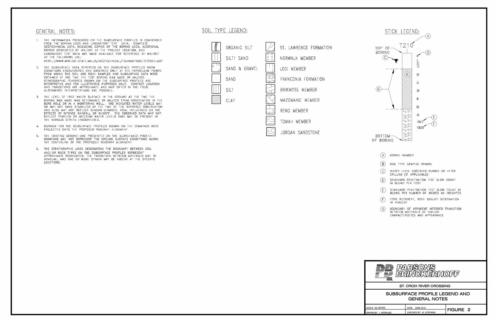


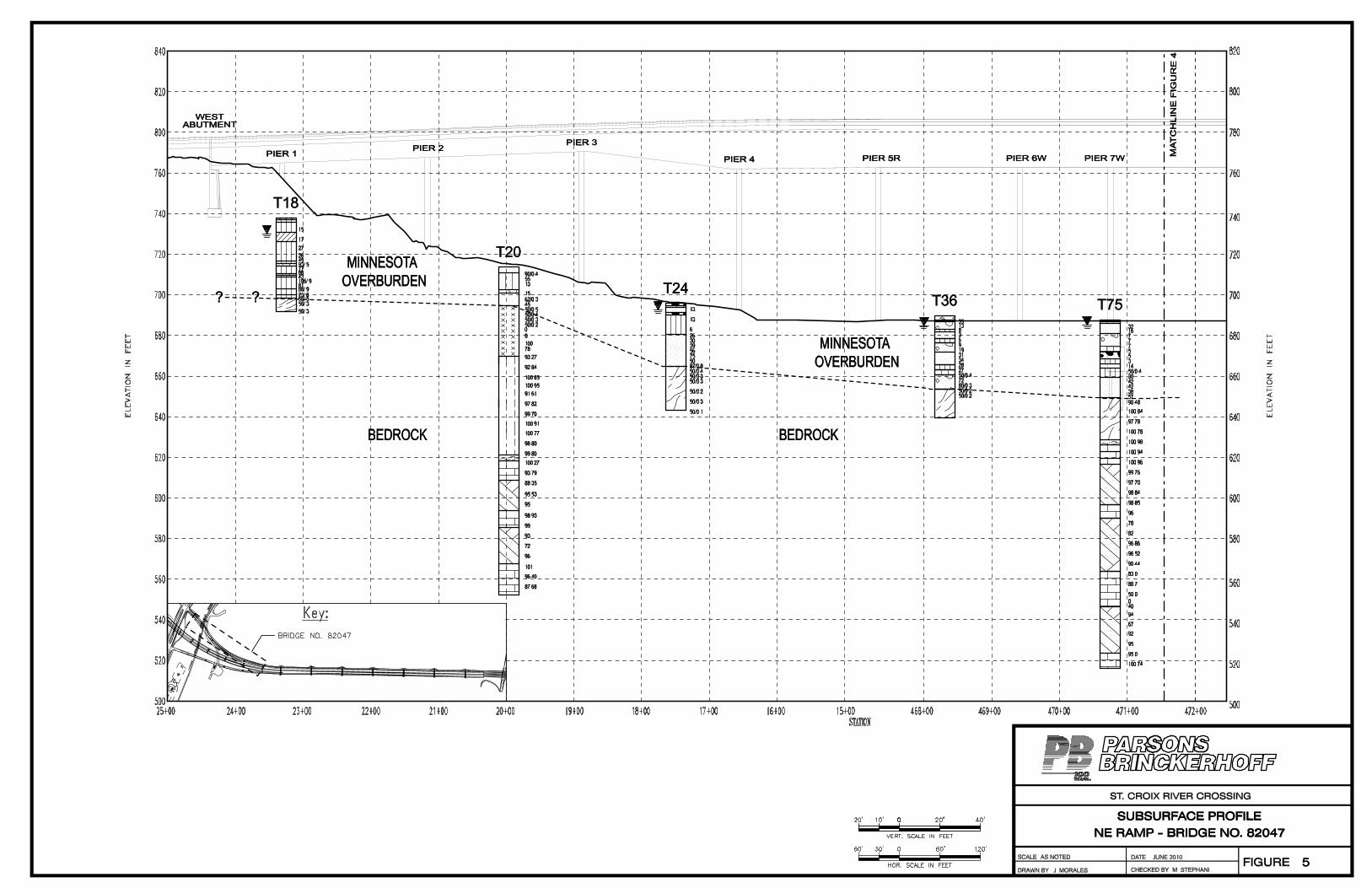


RQD vs Elevation
500
520
540
560
580
600
620
640
660
680
0 20 40 60 80 100
RQD (%)
Elevation (ft)
Franconia ‐ Mazomanie
Franconia ‐ Reno
Franconia ‐ Tomah
Jordan Sandstone
St. Lawrence ‐ Lodi

Unconfined Compressive Strength vs. Elevation
500
520
540
560
580
600
620
640
660
680
0 3,000 6,000 9,000 12,000
Unconfined Compressive Strength (psi)
Elevation (ft)
Franconia ‐ Maxomanie
Franconia ‐ Reno
Franconia ‐ Tomah
Jordan Sandstone
St. Lawrence ‐ Lodi