foundation radio amateur examination specification · foundation syllabus page 3 of 26 issue 8e...
TRANSCRIPT
Foundation Radio Amateur Examination
Specification
For Examinations held after 1 July 2011
Publication date: April 2017
Document EX 501
Foundation Syllabus Page 2 of 26 Issue 8e
Contents
Section Page
1 Introduction 3
2 Syllabus 7
3 Assessment Schedule 24
4 Frequency Allocation Table 25
5 Frequency to Wavelength Conversion Chart 26
Document changes
Issue 7 June 2008 Sections 3b2 and 3b3 merged as 3b3. Section 3b1 renumbered 3b2. New section 3b1 on conductors and insulators.
Issue 8 June 2010 for July 2011
New sections 8a.5 and 8a.6. Existing 8a.5 renumbered as 8a.7
Issue 8a June 2013 Add text to the Introduction on the aim of the examination.
Reference to Optical Marking and other editorial changes for clarity in the Introduction. Time changed to 55 minutes to allow time to complete the OM sheet.
No change to the syllabus.
Issue 8b September 2013
Editorial correction; time allowed 55 minutes.
Issue 8c July 2014 Editorial correction, reference to syllabus item 10a had been omitted in the Introduction, now inserted.
Issue 8d January 2015
Added sentence to paragraph 1 of Candidates with Disabilities, page 4, to allow a substitute assessment where a critical skill is being assessed and a waiver is inappropriate.
No change to the syllabus.
Issue 8e April 2017 Removed example band plan and replaced with reference to the ‘Reference Data for use in the Foundation Level Examination’. Layout modified to RSGB branding.
Foundation Syllabus Page 3 of 26 Issue 8e
Section 1
Introduction
The Foundation Radio Amateur Examination is part of a structured suite of three examinations recognised by Ofcom to give access to the amateur radio bands. All prospective radio amateurs must demonstrate a suitable level of competence and proficiency as a pre-requisite to holding a licence.
The Foundation Licence is the entry level to amateur radio. It is intended to provide an exciting introduction to the hobby whilst requiring an acceptable minimum level of skill and experience.
The aim of the suite of examinations is to verify and assure the regulator that successful candidates have
knowledge of the legal and ethical requirements of amateur radio
an understanding of safe working practices and are mindful of the safety of others
a secure foundation for further study of radio science and technology
knowledge of good operating practices and procedures
an understanding of basic electronic components and systems relevant to amateur radio
an understanding of simple radio communications equipment through the
construction of radio related projects, fault finding and remediation
to a standard appropriate to the level of amateur radio licence addressed by their examination.
This syllabus sets out the requirements for the first tier in the 3 tier structure consisting of Foundation, Intermediate and Full examinations.
Key Features
Part of a progressive system of learning designed to promote an understanding of radio communications science, technology and practice sufficient to allow the licensed operator to work safely on the amateur radio bands.
Clear presentation of content for easy reference.
The examination suite as a whole provides a backbone of theoretical knowledge whilst at the same time requiring ‘On-air’ experience and practical skills.
A student’s workbook is available covering the syllabus and is suitable for self-study if desired.
Can be used within schools to enrich the Science and Technology curriculum.
The Assessment
Two methods of assessment are used. A Practical Assessment detailed in sections 8e, 8f and 10a of the syllabus requires demonstration of setting up a radio transmitter/receiver, correct on-air operating and a simple introduction to Morse code. These items must be assessed by a Registered Assessor, who may also be the tutor. This is followed by an examination of 26 multiple-choice questions, each with 4 possible responses, which covers the remainder of the syllabus. The examination lasts 55 minutes.
The examination should normally be sat within 12 months of completing the Practical Assessment.

Foundation Syllabus Page 4 of 26 Issue 8e
Papers are available at two week’s notice. These are indicatively marked locally subject to validation using the Optical Mark Sheet.
The results will also be uploaded to the Ofcom licensing database. Candidates will use their candidate number and password to make on-line application for their licence. A postal application option is available.
Examinations must be carried out at an RSGB registered centre.
Prior Learning and Progression
As this is the entry point, no prior subject knowledge is required. There are no set age limits.
Progression is to the Intermediate licence and may be subsequently followed by the Full licence examination. The candidate may progress at his or her own pace, but must pass the examinations in ascending order. At Foundation and Intermediate level the practical assessment must be completed before taking the relevant examination. It is permissible to undertake Intermediate practical assessments before sitting the Foundation examination but the candidate should then sit the Intermediate within 12 months. The Advanced level examination does not include a practical assessment.
Candidates with disabilities
Arrangements can be made for candidates with disabilities to demonstrate skills and knowledge by whatever means is judged appropriate. Where critical skills, such as on-air operation, are involved the requirement can be modified to reflect the candidate's normal method of working1.
Applications for special arrangements should be made well in advance of the examination to the Radio Society of Great Britain (RSGB) and will normally require a medical certificate advising the appropriate method of assessment or examination. Any waiver granted will be shown on the Register and Assessment Sheet (RAS) issued by the RSGB Examination Department.
Appeals after the examination citing disabilities or learning difficulties not previously declared cannot be considered.
Examination Department Radio Society of Great Britain 3 Abbey Court Fraser Road Priory Business Park Bedford MK44 3WH
The syllabus
The key points of study are shown under Assessment Objectives. The words “recall” and
“understand” are used to denote differing levels of comprehension.
Recall indicates the need to remember a fact and apply it fairly directly to a question or situation. A thorough understanding of why the fact is so and the full range of circumstances in which it is applicable is not required, but questions will expect a basic understanding.
An example is objective 3b.1 which requires knowledge of the formula P=VI, what the letters stand for and the ability to perform a calculation given any two of the factors. The question will not normally require the use of a calculator since no useful purpose is served by making the question arithmetically difficult. Alternatively, the question may ask the
1 The RSGB Examination Group must be consulted in advance to agree the required change.
Foundation Syllabus Page 5 of 26 Issue 8e
effect of, for example, of doubling or halving one of the factors. Another example is objective 1a.1. The candidate needs to know that amateur radio is non-commercial, and not used to discuss business or negotiate the sale of amateur equipment in a commercial context.
Understand indicates the need for a more detailed knowledge of the subject, understanding why the point is correct and the range of circumstances in which it is relevant and applicable.
Typically, this will be where the candidates will find themselves having to make judgements or apply a practice to a wider range of circumstances. 4b.6 is an example concerning over modulation where the candidate needs to appreciate the cause and effect and its implications so that there is an incentive to avoid the problems of over modulation. Also, in 9c.1, for example, regarding trailing wires, the student may meet a wide variety of situations and needs to be able to apply the basic rule to whatever circumstances occur. An ability to analyse the safety of the situation is needed which requires an understanding of how problems may develop and what different risks are involved.
Examination Questions
Examination questions may assume background knowledge of the basic principles from all parts of the Foundation syllabus; questions themselves will be clearly aimed at the relevant syllabus item.
It will be assumed that the candidate has some familiarity with operating practices and procedures covered in the Foundation practical assessment.
Examination Schedule
The schedule shows the allocation of syllabus topics to questions on the examination paper.
Pass Mark
The pass mark is 73% or 19 correct questions out of a total of 26.
Language
The language of assessment will be English.
Training
Attendance at a training course is not compulsory but is very strongly advised. Many of the practical activities on-air require the presence of a licensed tutor to guide the candidate and correct errors as they occur. This is not readily achievable with reading material alone although multi-media distant learning materials will be of considerable benefit.
The practical assessments are intended to be interactive, so a candidate who is obliged to be self taught may demonstrate his or her skills and receive guidance should that be necessary. The topic is ’signed off’ once a good standard has been reached without coaching. Candidates who are not on a training course are advised not to place too much reliance on this procedure since time may be limited and several candidates may need to be assessed.
Sample question papers are available from the RSGB (www.rsgb.org.uk).
Updates
Updates to this syllabus will be made from time to time and the latest version can be obtained from the RSGB website. Where the update involves a significant change to the syllabus content, the date from which the syllabus is valid for examinations will be
Foundation Syllabus Page 6 of 26 Issue 8e
amended to show the new period of validity of the syllabus. A minimum of three months notice will be given.
Tutors should note that external changes, such as to licence conditions, may occur at less than three months notice, which may result in examinations being set on the previous conditions immediately after the change. Changes to the licence schedule and band plans should not affect the examination because those documents are provided for reference. It should also be noted that the band plans provided in the Foundation examination are simplified from those produced by the IARU.
Foundation Syllabus Page 7 Issue 8e
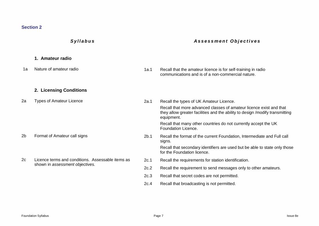
Section 2
S y l l a b u s A s s e s s m e n t O b j e c t i v e s
1. Amateur radio
1a Nature of amateur radio 1a.1 Recall that the amateur licence is for self-training in radio communications and is of a non-commercial nature.
2. Licensing Conditions
2a Types of Amateur Licence 2a.1 Recall the types of UK Amateur Licence.
Recall that more advanced classes of amateur licence exist and that they allow greater facilities and the ability to design /modify transmitting equipment.
Recall that many other countries do not currently accept the UK Foundation Licence.
2b Format of Amateur call signs 2b.1 Recall the format of the current Foundation, Intermediate and Full call signs.
Recall that secondary identifiers are used but be able to state only those for the Foundation licence.
2c Licence terms and conditions. Assessable items as shown in assessment objectives.
2c.1 Recall the requirements for station identification.
2c.2 Recall the requirement to send messages only to other amateurs.
2c.3 Recall that secret codes are not permitted.
2c.4 Recall that broadcasting is not permitted.
Foundation Syllabus Page 8 Issue 8e
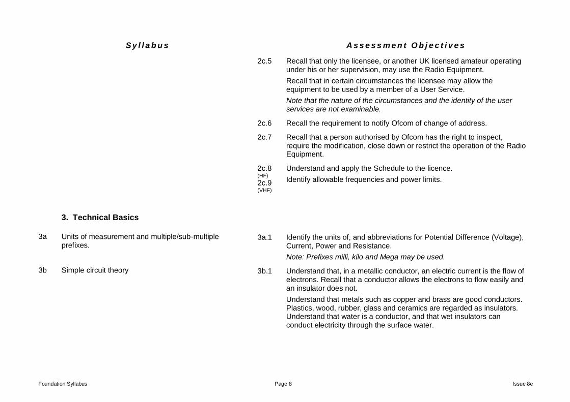
S y l l a b u s A s s e s s m e n t O b j e c t i v e s
2c.5 Recall that only the licensee, or another UK licensed amateur operating under his or her supervision, may use the Radio Equipment.
Recall that in certain circumstances the licensee may allow the equipment to be used by a member of a User Service.
Note that the nature of the circumstances and the identity of the user services are not examinable.
2c.6 Recall the requirement to notify Ofcom of change of address.
2c.7 Recall that a person authorised by Ofcom has the right to inspect, require the modification, close down or restrict the operation of the Radio Equipment.
2c.8 (HF) 2c.9 (VHF)
Understand and apply the Schedule to the licence.
Identify allowable frequencies and power limits.
3. Technical Basics
3a Units of measurement and multiple/sub-multiple prefixes.
3a.1 Identify the units of, and abbreviations for Potential Difference (Voltage), Current, Power and Resistance.
Note: Prefixes milli, kilo and Mega may be used.
3b Simple circuit theory 3b.1 Understand that, in a metallic conductor, an electric current is the flow of electrons. Recall that a conductor allows the electrons to flow easily and an insulator does not.
Understand that metals such as copper and brass are good conductors. Plastics, wood, rubber, glass and ceramics are regarded as insulators. Understand that water is a conductor, and that wet insulators can conduct electricity through the surface water.
Foundation Syllabus Page 9 Issue 8e
S y l l a b u s A s s e s s m e n t O b j e c t i v e s
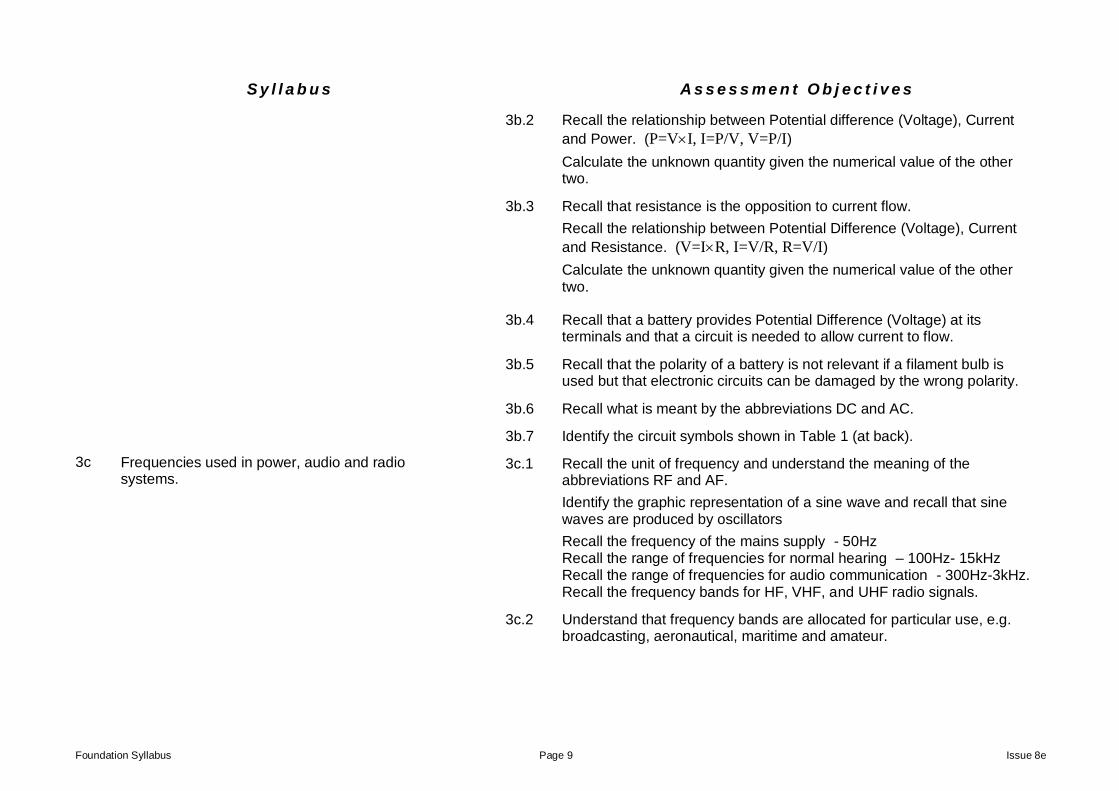
3b.2 Recall the relationship between Potential difference (Voltage), Current
and Power. (P=VI, I=P/V, V=P/I)
Calculate the unknown quantity given the numerical value of the other two.
3b.3
Recall that resistance is the opposition to current flow.
Recall the relationship between Potential Difference (Voltage), Current
and Resistance. (V=IR, I=V/R, R=V/I)
Calculate the unknown quantity given the numerical value of the other two.
3b.4 Recall that a battery provides Potential Difference (Voltage) at its terminals and that a circuit is needed to allow current to flow.
3b.5 Recall that the polarity of a battery is not relevant if a filament bulb is used but that electronic circuits can be damaged by the wrong polarity.
3b.6 Recall what is meant by the abbreviations DC and AC.
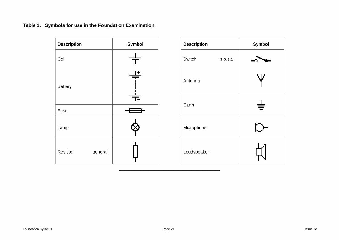
3b.7 Identify the circuit symbols shown in Table 1 (at back).
3c Frequencies used in power, audio and radio systems.
3c.1 Recall the unit of frequency and understand the meaning of the abbreviations RF and AF.
Identify the graphic representation of a sine wave and recall that sine waves are produced by oscillators
Recall the frequency of the mains supply - 50Hz Recall the range of frequencies for normal hearing – 100Hz- 15kHz Recall the range of frequencies for audio communication - 300Hz-3kHz. Recall the frequency bands for HF, VHF, and UHF radio signals.
3c.2 Understand that frequency bands are allocated for particular use, e.g. broadcasting, aeronautical, maritime and amateur.
Foundation Syllabus Page 10 Issue 8e
S y l l a b u s A s s e s s m e n t O b j e c t i v e s
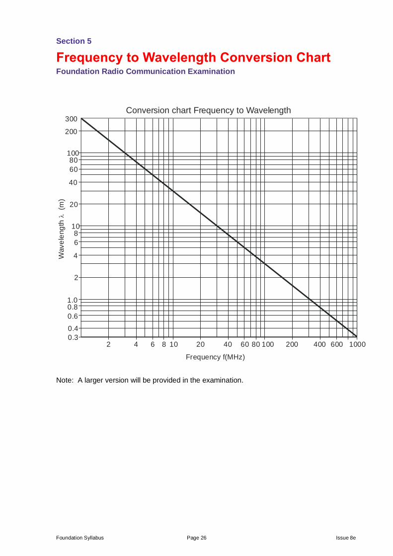
3c.3 Understand the relationship between frequency (f) and wavelength (). Use a graph to convert from one to the other.
Note: calculations are not required.
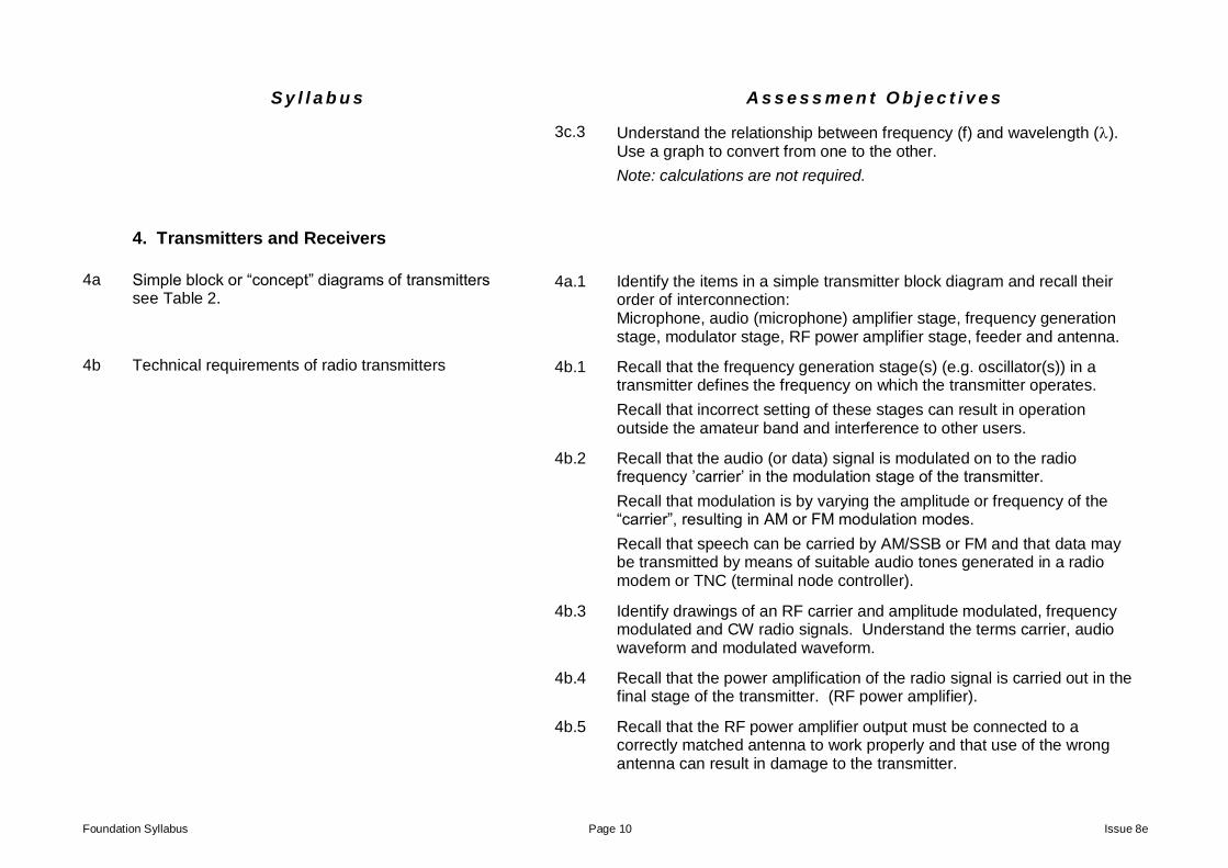
4. Transmitters and Receivers
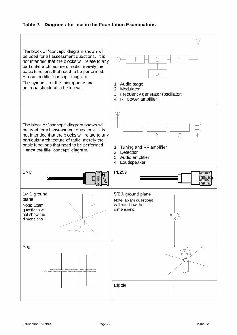
4a Simple block or “concept” diagrams of transmitters see Table 2.
4a.1 Identify the items in a simple transmitter block diagram and recall their order of interconnection: Microphone, audio (microphone) amplifier stage, frequency generation stage, modulator stage, RF power amplifier stage, feeder and antenna.
4b Technical requirements of radio transmitters 4b.1 Recall that the frequency generation stage(s) (e.g. oscillator(s)) in a transmitter defines the frequency on which the transmitter operates.
Recall that incorrect setting of these stages can result in operation outside the amateur band and interference to other users.
4b.2 Recall that the audio (or data) signal is modulated on to the radio frequency ’carrier’ in the modulation stage of the transmitter.
Recall that modulation is by varying the amplitude or frequency of the “carrier”, resulting in AM or FM modulation modes.
Recall that speech can be carried by AM/SSB or FM and that data may be transmitted by means of suitable audio tones generated in a radio modem or TNC (terminal node controller).
4b.3 Identify drawings of an RF carrier and amplitude modulated, frequency modulated and CW radio signals. Understand the terms carrier, audio waveform and modulated waveform.
4b.4 Recall that the power amplification of the radio signal is carried out in the final stage of the transmitter. (RF power amplifier).
4b.5 Recall that the RF power amplifier output must be connected to a correctly matched antenna to work properly and that use of the wrong antenna can result in damage to the transmitter.
Foundation Syllabus Page 11 Issue 8e
S y l l a b u s A s s e s s m e n t O b j e c t i v e s
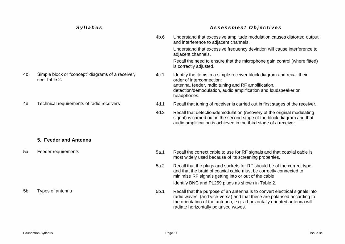
4b.6 Understand that excessive amplitude modulation causes distorted output and interference to adjacent channels.
Understand that excessive frequency deviation will cause interference to adjacent channels.
Recall the need to ensure that the microphone gain control (where fitted) is correctly adjusted.
4c Simple block or “concept” diagrams of a receiver, see Table 2.
4c.1 Identify the items in a simple receiver block diagram and recall their order of interconnection: antenna, feeder, radio tuning and RF amplification, detection/demodulation, audio amplification and loudspeaker or headphones.
4d Technical requirements of radio receivers 4d.1 Recall that tuning of receiver is carried out in first stages of the receiver.
4d.2 Recall that detection/demodulation (recovery of the original modulating signal) is carried out in the second stage of the block diagram and that audio amplification is achieved in the third stage of a receiver.
5. Feeder and Antenna
5a Feeder requirements 5a.1 Recall the correct cable to use for RF signals and that coaxial cable is most widely used because of its screening properties.
5a.2 Recall that the plugs and sockets for RF should be of the correct type and that the braid of coaxial cable must be correctly connected to minimise RF signals getting into or out of the cable.
Identify BNC and PL259 plugs as shown in Table 2.
5b Types of antenna 5b.1 Recall that the purpose of an antenna is to convert electrical signals into radio waves (and vice-versa) and that these are polarised according to the orientation of the antenna, e.g. a horizontally oriented antenna will radiate horizontally polarised waves.
Foundation Syllabus Page 12 Issue 8e
S y l l a b u s A s s e s s m e n t O b j e c t i v e s
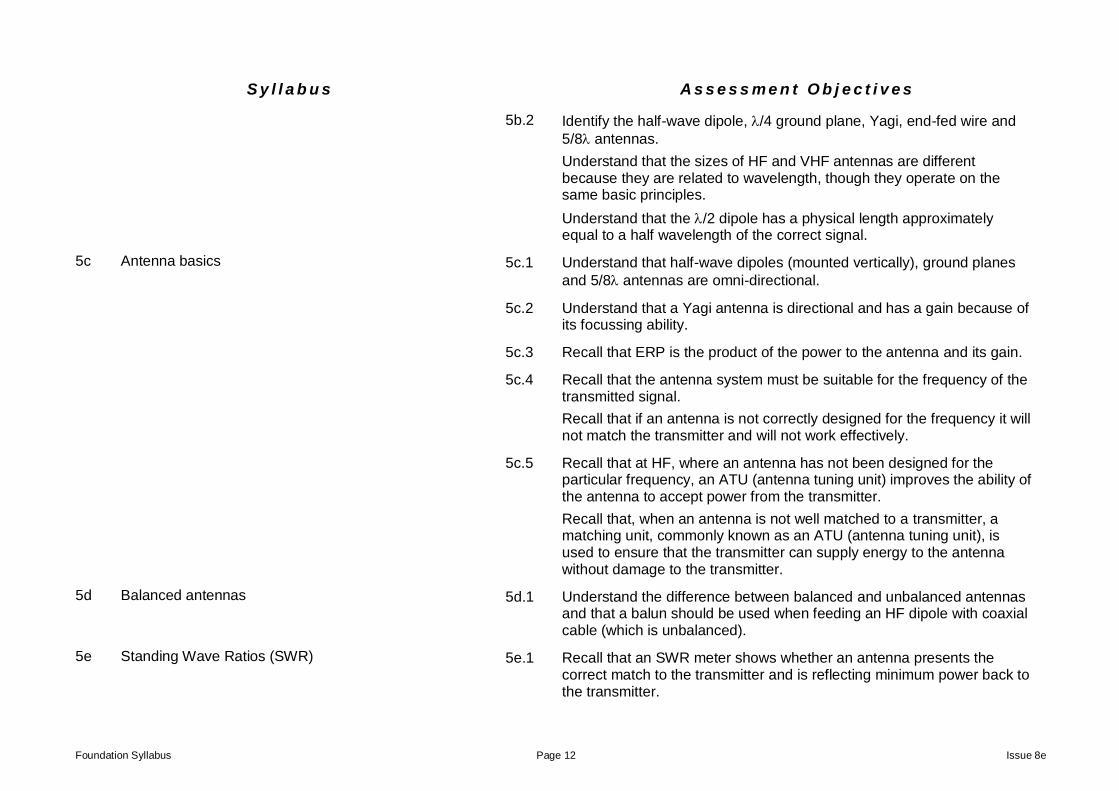
5b.2 Identify the half-wave dipole, /4 ground plane, Yagi, end-fed wire and
5/8 antennas.
Understand that the sizes of HF and VHF antennas are different because they are related to wavelength, though they operate on the same basic principles.
Understand that the /2 dipole has a physical length approximately equal to a half wavelength of the correct signal.
5c Antenna basics 5c.1 Understand that half-wave dipoles (mounted vertically), ground planes
and 5/8 antennas are omni-directional.
5c.2 Understand that a Yagi antenna is directional and has a gain because of its focussing ability.
5c.3 Recall that ERP is the product of the power to the antenna and its gain.
5c.4 Recall that the antenna system must be suitable for the frequency of the transmitted signal.
Recall that if an antenna is not correctly designed for the frequency it will not match the transmitter and will not work effectively.
5c.5 Recall that at HF, where an antenna has not been designed for the particular frequency, an ATU (antenna tuning unit) improves the ability of the antenna to accept power from the transmitter.
Recall that, when an antenna is not well matched to a transmitter, a matching unit, commonly known as an ATU (antenna tuning unit), is used to ensure that the transmitter can supply energy to the antenna without damage to the transmitter.
5d Balanced antennas 5d.1 Understand the difference between balanced and unbalanced antennas and that a balun should be used when feeding an HF dipole with coaxial cable (which is unbalanced).
5e Standing Wave Ratios (SWR) 5e.1 Recall that an SWR meter shows whether an antenna presents the correct match to the transmitter and is reflecting minimum power back to the transmitter.
Foundation Syllabus Page 13 Issue 8e
S y l l a b u s A s s e s s m e n t O b j e c t i v e s
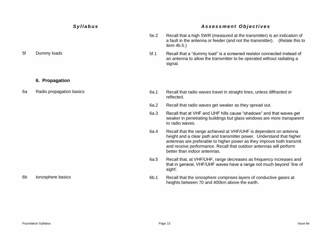
5e.2 Recall that a high SWR (measured at the transmitter) is an indication of a fault in the antenna or feeder (and not the transmitter). (Relate this to item 4b.5.)
5f Dummy loads 5f.1 Recall that a “dummy load” is a screened resistor connected instead of an antenna to allow the transmitter to be operated without radiating a signal.
6. Propagation
6a Radio propagation basics 6a.1 Recall that radio waves travel in straight lines, unless diffracted or reflected.
6a.2 Recall that radio waves get weaker as they spread out.
6a.3 Recall that at VHF and UHF hills cause “shadows” and that waves get weaker in penetrating buildings but glass windows are more transparent to radio waves.
6a.4 Recall that the range achieved at VHF/UHF is dependent on antenna height and a clear path and transmitter power. Understand that higher antennas are preferable to higher power as they improve both transmit and receive performance. Recall that outdoor antennas will perform better than indoor antennas.
6a.5 Recall that, at VHF/UHF, range decreases as frequency increases and that in general, VHF/UHF waves have a range not much beyond ’line of sight’.
6b Ionosphere basics 6b.1 Recall that the ionosphere comprises layers of conductive gases at heights between 70 and 400km above the earth.
Foundation Syllabus Page 14 Issue 8e
S y l l a b u s A s s e s s m e n t O b j e c t i v e s
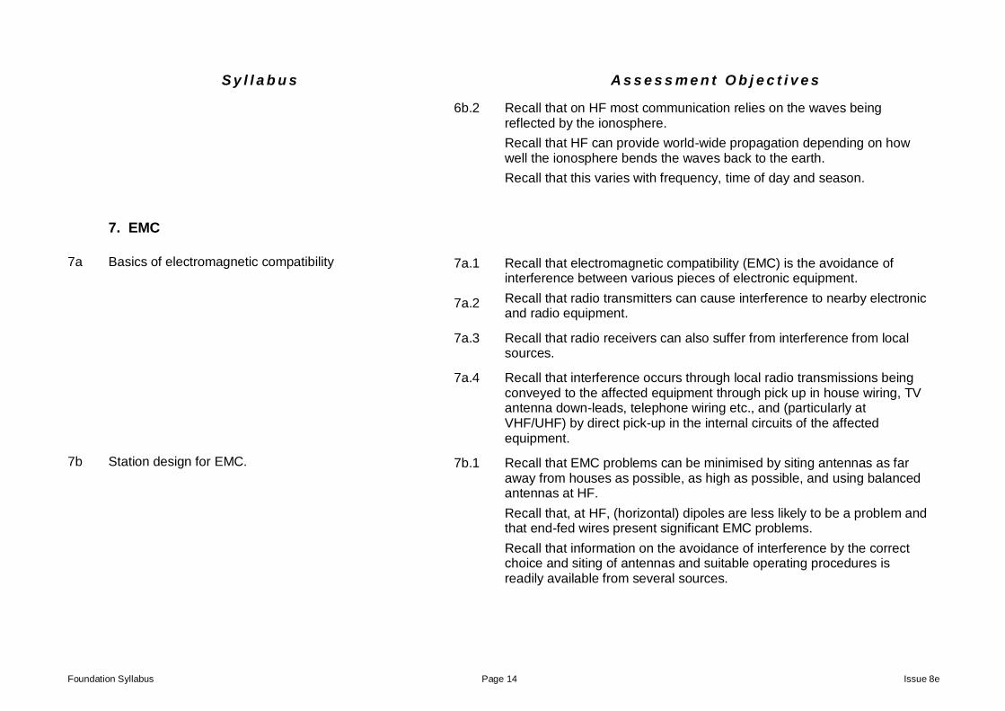
6b.2 Recall that on HF most communication relies on the waves being reflected by the ionosphere.
Recall that HF can provide world-wide propagation depending on how well the ionosphere bends the waves back to the earth.
Recall that this varies with frequency, time of day and season.
7. EMC
7a Basics of electromagnetic compatibility 7a.1 Recall that electromagnetic compatibility (EMC) is the avoidance of interference between various pieces of electronic equipment.
7a.2 Recall that radio transmitters can cause interference to nearby electronic and radio equipment.
7a.3 Recall that radio receivers can also suffer from interference from local sources.
7a.4 Recall that interference occurs through local radio transmissions being conveyed to the affected equipment through pick up in house wiring, TV antenna down-leads, telephone wiring etc., and (particularly at VHF/UHF) by direct pick-up in the internal circuits of the affected equipment.
7b Station design for EMC. 7b.1 Recall that EMC problems can be minimised by siting antennas as far away from houses as possible, as high as possible, and using balanced antennas at HF.
Recall that, at HF, (horizontal) dipoles are less likely to be a problem and that end-fed wires present significant EMC problems.
Recall that information on the avoidance of interference by the correct choice and siting of antennas and suitable operating procedures is readily available from several sources.
Foundation Syllabus Page 15 Issue 8e
S y l l a b u s A s s e s s m e n t O b j e c t i v e s
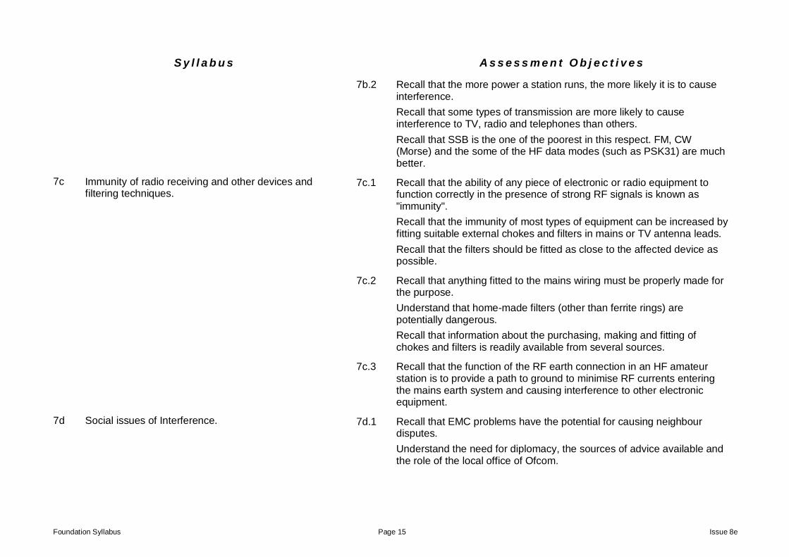
7b.2 Recall that the more power a station runs, the more likely it is to cause interference.
Recall that some types of transmission are more likely to cause interference to TV, radio and telephones than others.
Recall that SSB is the one of the poorest in this respect. FM, CW (Morse) and the some of the HF data modes (such as PSK31) are much better.
7c Immunity of radio receiving and other devices and filtering techniques.
7c.1 Recall that the ability of any piece of electronic or radio equipment to function correctly in the presence of strong RF signals is known as "immunity".
Recall that the immunity of most types of equipment can be increased by fitting suitable external chokes and filters in mains or TV antenna leads.
Recall that the filters should be fitted as close to the affected device as possible.
7c.2 Recall that anything fitted to the mains wiring must be properly made for the purpose.
Understand that home-made filters (other than ferrite rings) are potentially dangerous.
Recall that information about the purchasing, making and fitting of chokes and filters is readily available from several sources.
7c.3 Recall that the function of the RF earth connection in an HF amateur station is to provide a path to ground to minimise RF currents entering the mains earth system and causing interference to other electronic equipment.
7d Social issues of Interference. 7d.1 Recall that EMC problems have the potential for causing neighbour disputes.
Understand the need for diplomacy, the sources of advice available and the role of the local office of Ofcom.
Foundation Syllabus Page 16 Issue 8e
S y l l a b u s A s s e s s m e n t O b j e c t i v e s
8. Operating Practices and Procedures.
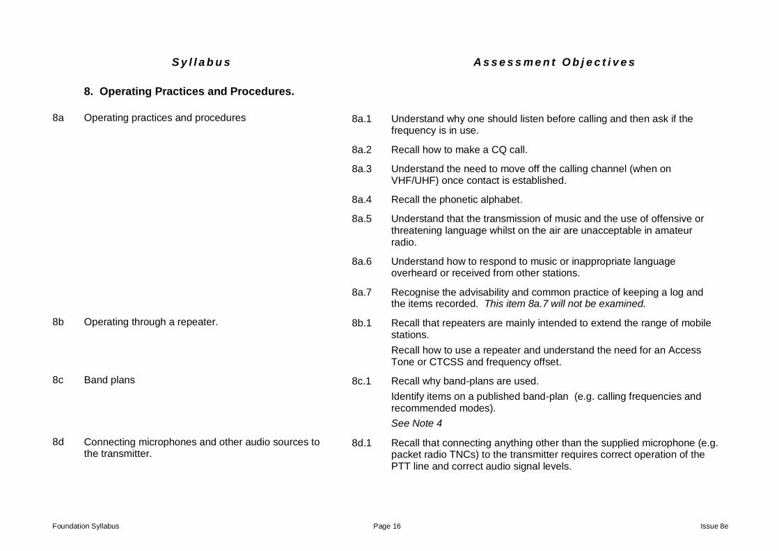
8a Operating practices and procedures 8a.1 Understand why one should listen before calling and then ask if the frequency is in use.
8a.2 Recall how to make a CQ call.
8a.3 Understand the need to move off the calling channel (when on VHF/UHF) once contact is established.
8a.4 Recall the phonetic alphabet.
8a.5 Understand that the transmission of music and the use of offensive or threatening language whilst on the air are unacceptable in amateur radio.
8a.6 Understand how to respond to music or inappropriate language overheard or received from other stations.
8a.7 Recognise the advisability and common practice of keeping a log and the items recorded. This item 8a.7 will not be examined.
8b Operating through a repeater. 8b.1 Recall that repeaters are mainly intended to extend the range of mobile stations.
Recall how to use a repeater and understand the need for an Access Tone or CTCSS and frequency offset.
8c Band plans 8c.1 Recall why band-plans are used.
Identify items on a published band-plan (e.g. calling frequencies and recommended modes).
See Note 4
8d Connecting microphones and other audio sources to the transmitter.
8d.1 Recall that connecting anything other than the supplied microphone (e.g. packet radio TNCs) to the transmitter requires correct operation of the PTT line and correct audio signal levels.
Foundation Syllabus Page 17 Issue 8e
S y l l a b u s A s s e s s m e n t O b j e c t i v e s
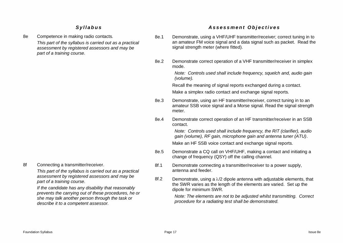
8e Competence in making radio contacts.
This part of the syllabus is carried out as a practical assessment by registered assessors and may be part of a training course.
8e.1 Demonstrate, using a VHF/UHF transmitter/receiver; correct tuning in to an amateur FM voice signal and a data signal such as packet. Read the signal strength meter (where fitted).
8e.2 Demonstrate correct operation of a VHF transmitter/receiver in simplex mode.
Note: Controls used shall include frequency, squelch and, audio gain (volume).
Recall the meaning of signal reports exchanged during a contact.
Make a simplex radio contact and exchange signal reports.
8e.3 Demonstrate, using an HF transmitter/receiver, correct tuning in to an amateur SSB voice signal and a Morse signal. Read the signal strength meter.
8e.4 Demonstrate correct operation of an HF transmitter/receiver in an SSB contact.
Note: Controls used shall include frequency, the RIT (clarifier), audio gain (volume), RF gain, microphone gain and antenna tuner (ATU).
Make an HF SSB voice contact and exchange signal reports.
8e.5 Demonstrate a CQ call on VHF/UHF, making a contact and initiating a change of frequency (QSY) off the calling channel.
8f Connecting a transmitter/receiver.
This part of the syllabus is carried out as a practical assessment by registered assessors and may be part of a training course.
If the candidate has any disability that reasonably prevents the carrying out of these procedures, he or she may talk another person through the task or describe it to a competent assessor.
8f.1 Demonstrate connecting a transmitter/receiver to a power supply, antenna and feeder.
8f.2 Demonstrate, using a /2 dipole antenna with adjustable elements, that the SWR varies as the length of the elements are varied. Set up the dipole for minimum SWR.
Note: The elements are not to be adjusted whilst transmitting. Correct procedure for a radiating test shall be demonstrated.
Foundation Syllabus Page 18 Issue 8e
S y l l a b u s A s s e s s m e n t O b j e c t i v e s
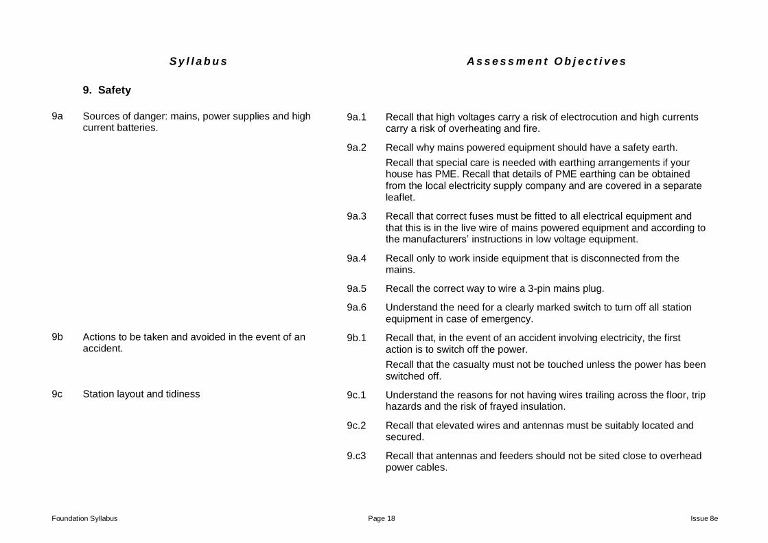
9. Safety
9a Sources of danger: mains, power supplies and high current batteries.
9a.1 Recall that high voltages carry a risk of electrocution and high currents carry a risk of overheating and fire.
9a.2 Recall why mains powered equipment should have a safety earth.
Recall that special care is needed with earthing arrangements if your house has PME. Recall that details of PME earthing can be obtained from the local electricity supply company and are covered in a separate leaflet.
9a.3 Recall that correct fuses must be fitted to all electrical equipment and that this is in the live wire of mains powered equipment and according to the manufacturers’ instructions in low voltage equipment.
9a.4 Recall only to work inside equipment that is disconnected from the mains.
9a.5 Recall the correct way to wire a 3-pin mains plug.
9a.6 Understand the need for a clearly marked switch to turn off all station equipment in case of emergency.
9b Actions to be taken and avoided in the event of an accident.
9b.1 Recall that, in the event of an accident involving electricity, the first action is to switch off the power.
Recall that the casualty must not be touched unless the power has been switched off.
9c Station layout and tidiness 9c.1 Understand the reasons for not having wires trailing across the floor, trip hazards and the risk of frayed insulation.
9c.2 Recall that elevated wires and antennas must be suitably located and secured.
9.c3 Recall that antennas and feeders should not be sited close to overhead power cables.

Foundation Syllabus Page 19 Issue 8e
S y l l a b u s A s s e s s m e n t O b j e c t i v e s
9c.4 Recall that antenna erection is potentially hazardous and that it is advisable to have someone to help you.
Understand the need for at least one adult to be present.
9c.5 Recall that antenna elements should not be touched whilst transmitting and should be mounted to avoid accidental contact.
Note: this does not apply to low powered devices such as hand-held equipment.
9c.6 Recall that particularly high antennas may need special protection against lightning.
9d Safe use of headphones 9d.1 Recall that excessive volume when wearing headphones can cause damage to hearing.
Foundation Syllabus Page 20 Issue 8e
S y l l a b u s A s s e s s m e n t O b j e c t i v e s
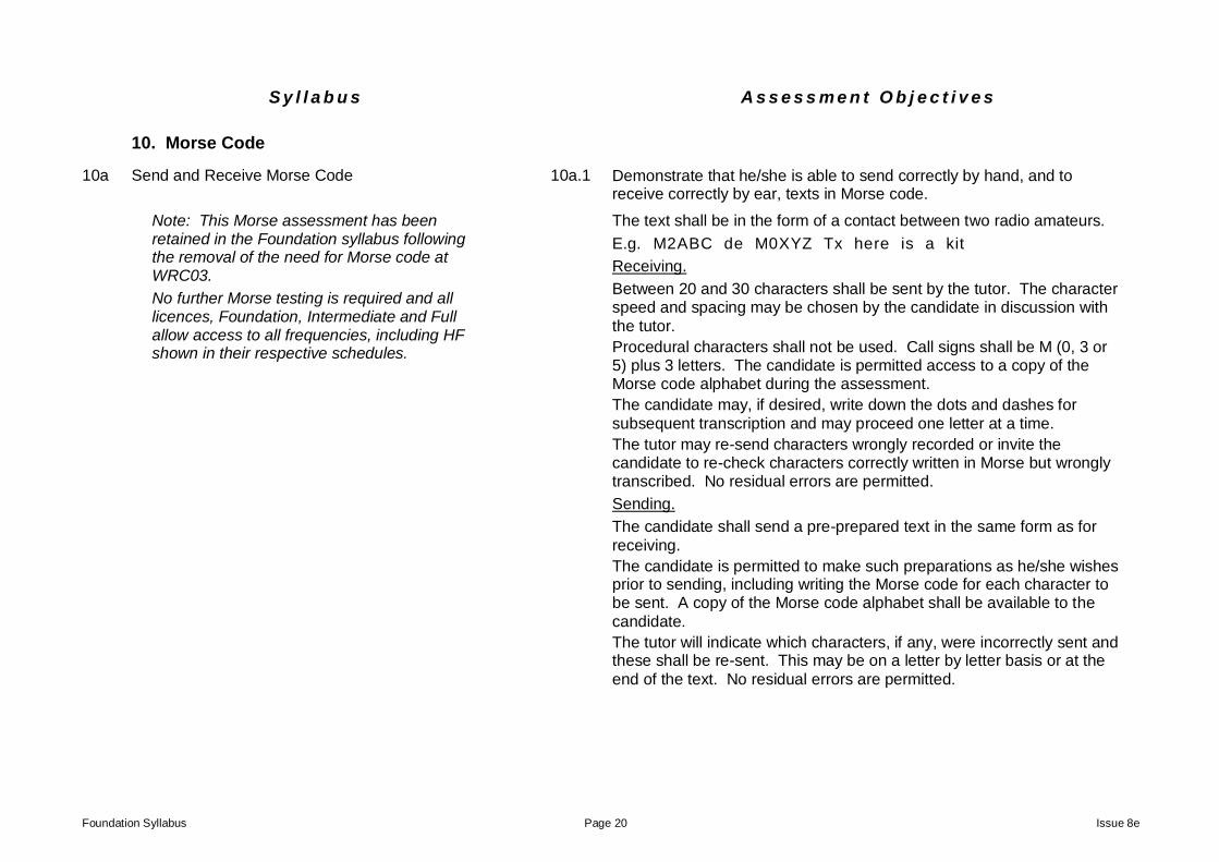
10. Morse Code
10a Send and Receive Morse Code 10a.1 Demonstrate that he/she is able to send correctly by hand, and to receive correctly by ear, texts in Morse code.
Note: This Morse assessment has been retained in the Foundation syllabus following the removal of the need for Morse code at WRC03.
No further Morse testing is required and all licences, Foundation, Intermediate and Full allow access to all frequencies, including HF shown in their respective schedules.
The text shall be in the form of a contact between two radio amateurs.
E.g. M2ABC de M0XYZ Tx here is a kit
Receiving.
Between 20 and 30 characters shall be sent by the tutor. The character speed and spacing may be chosen by the candidate in discussion with
the tutor.
Procedural characters shall not be used. Call signs shall be M (0, 3 or 5) plus 3 letters. The candidate is permitted access to a copy of the Morse code alphabet during the assessment.
The candidate may, if desired, write down the dots and dashes for
subsequent transcription and may proceed one letter at a time.
The tutor may re-send characters wrongly recorded or invite the candidate to re-check characters correctly written in Morse but wrongly transcribed. No residual errors are permitted.
Sending.
The candidate shall send a pre-prepared text in the same form as for
receiving.
The candidate is permitted to make such preparations as he/she wishes prior to sending, including writing the Morse code for each character to be sent. A copy of the Morse code alphabet shall be available to the
candidate.
The tutor will indicate which characters, if any, were incorrectly sent and these shall be re-sent. This may be on a letter by letter basis or at the
end of the text. No residual errors are permitted.
Foundation Syllabus Page 21 Issue 8e
Table 1. Symbols for use in the Foundation Examination.
Description Symbol Description Symbol
Cell
Switch s.p.s.t.
Battery
Antenna
Earth Fuse
Lamp
Microphone
Resistor general
Loudspeaker
_________________________________________
Foundation Syllabus Page 22 Issue 8e
Table 2. Diagrams for use in the Foundation Examination.
The block or “concept” diagram shown will be used for all assessment questions. It is not intended that the blocks will relate to any particular architecture of radio, merely the basic functions that need to be performed. Hence the title “concept” diagram.
The symbols for the microphone and antenna should also be known.
1. Audio stage 2. Modulator 3. Frequency generator (oscillator) 4. RF power amplifier
The block or “concept” diagram shown will be used for all assessment questions. It is not intended that the blocks will relate to any particular architecture of radio, merely the basic functions that need to be performed. Hence the title “concept” diagram.
1. Tuning and RF amplifier 2. Detection 3. Audio amplifier 4. Loudspeaker
BNC PL259
1/4 ground
plane
Note: Exam questions will not show the dimensions.
5/8 ground plane
Note: Exam questions will not show the dimensions.
Yagi
Dipole
Foundation Syllabus Page 23 Issue 8e
Notes.
1. Assessment consists of practical exercises shown in sections 8e and 8f of this syllabus, which must be completed before sitting the examination. The exam consists of 26 multiple-choice questions each with 4 possible answers only one of which is correct. No marks are deducted for wrong answers. The pass mark is 19 questions correctly answered and all questions carry equal marks.
2. Requests for examinations should be made in the first instance to the Radio Society of Great Britain, telephone 01234 832 700, e-mail [email protected] who will be able to put you in touch with a local exam centre.
3. It is strongly advised that prospective candidates consider joining a suitable training course leading to the practical assessment and examination.
4. Band Plans are produced and revised by the International Amateur Radio Union (IARU) in conjunction with national societies (RSGB for UK). Consequently the Band Plan used for examination purposes and relevant questions in the Bank, will, from time to time, lag behind the current IARU plans.
The examination will be based on the version shown in the booklet ‘Reference Data for use in the Foundation Level Examination’, EX307. http://rsgb.org/main/clubs-training/forms/
At least six months’ notice of a revised booklet will be given in ‘Examination announcements’ http://rsgb.org/main/clubs-training/examination-announcements/
5. New syllabuses will be issued periodically and will show the date from which they will become valid. Notice will always be given but it is incumbent on students and tutors to confirm that they are working to the current version. The effective date of the syllabus is shown on the title page, in the title block. A re-issue of the syllabus without change of operative date, indicates that no changes relevant to the examination, have been made.
Foundation Syllabus Page 24 Issue 8e
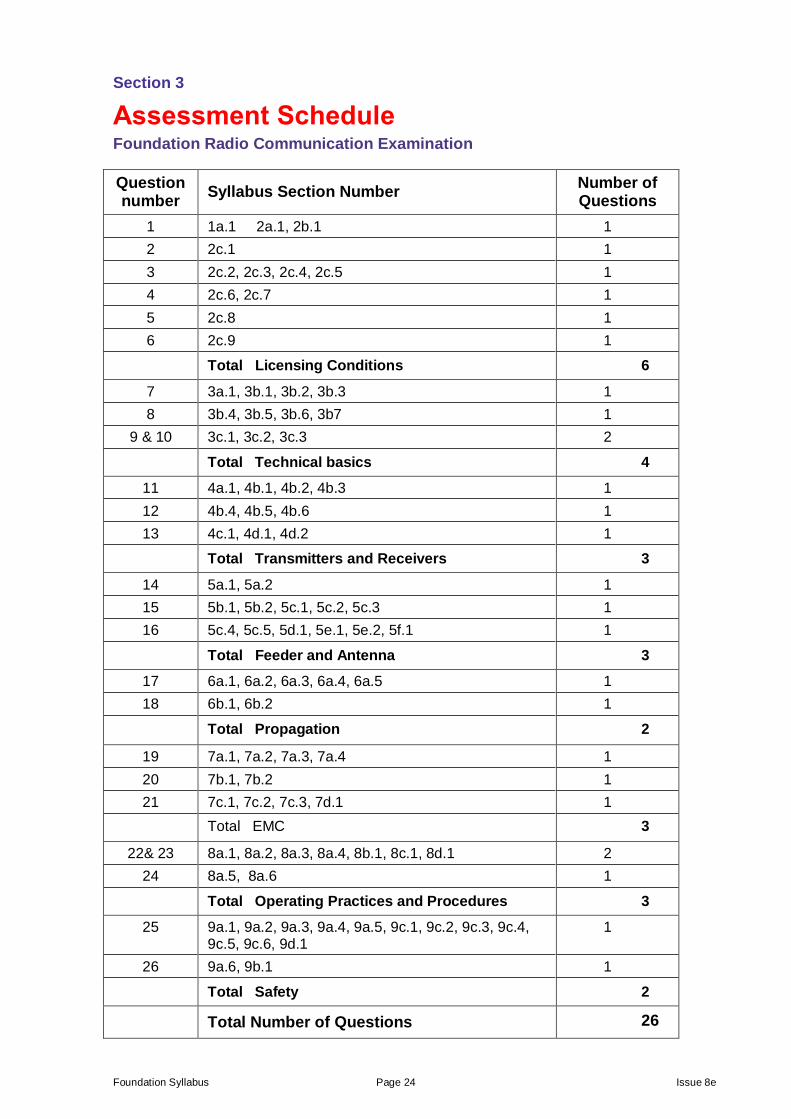
Section 3
Assessment Schedule Foundation Radio Communication Examination
Question number
Syllabus Section Number Number of Questions
1 1a.1 2a.1, 2b.1 1
2 2c.1 1
3 2c.2, 2c.3, 2c.4, 2c.5 1
4 2c.6, 2c.7 1
5 2c.8 1
6 2c.9 1
Total Licensing Conditions 6
7 3a.1, 3b.1, 3b.2, 3b.3 1
8 3b.4, 3b.5, 3b.6, 3b7 1
9 & 10 3c.1, 3c.2, 3c.3 2
Total Technical basics 4
11 4a.1, 4b.1, 4b.2, 4b.3 1
12 4b.4, 4b.5, 4b.6 1
13 4c.1, 4d.1, 4d.2 1
Total Transmitters and Receivers 3
14 5a.1, 5a.2 1
15 5b.1, 5b.2, 5c.1, 5c.2, 5c.3 1
16 5c.4, 5c.5, 5d.1, 5e.1, 5e.2, 5f.1 1
Total Feeder and Antenna 3
17 6a.1, 6a.2, 6a.3, 6a.4, 6a.5 1
18 6b.1, 6b.2 1
Total Propagation 2
19 7a.1, 7a.2, 7a.3, 7a.4 1
20 7b.1, 7b.2 1
21 7c.1, 7c.2, 7c.3, 7d.1 1
Total EMC 3
22& 23 8a.1, 8a.2, 8a.3, 8a.4, 8b.1, 8c.1, 8d.1 2
24 8a.5, 8a.6 1
Total Operating Practices and Procedures 3
25 9a.1, 9a.2, 9a.3, 9a.4, 9a.5, 9c.1, 9c.2, 9c.3, 9c.4, 9c.5, 9c.6, 9d.1
1
26 9a.6, 9b.1 1
Total Safety 2
Total Number of Questions 26
Foundation Syllabus Page 25 Issue 8e
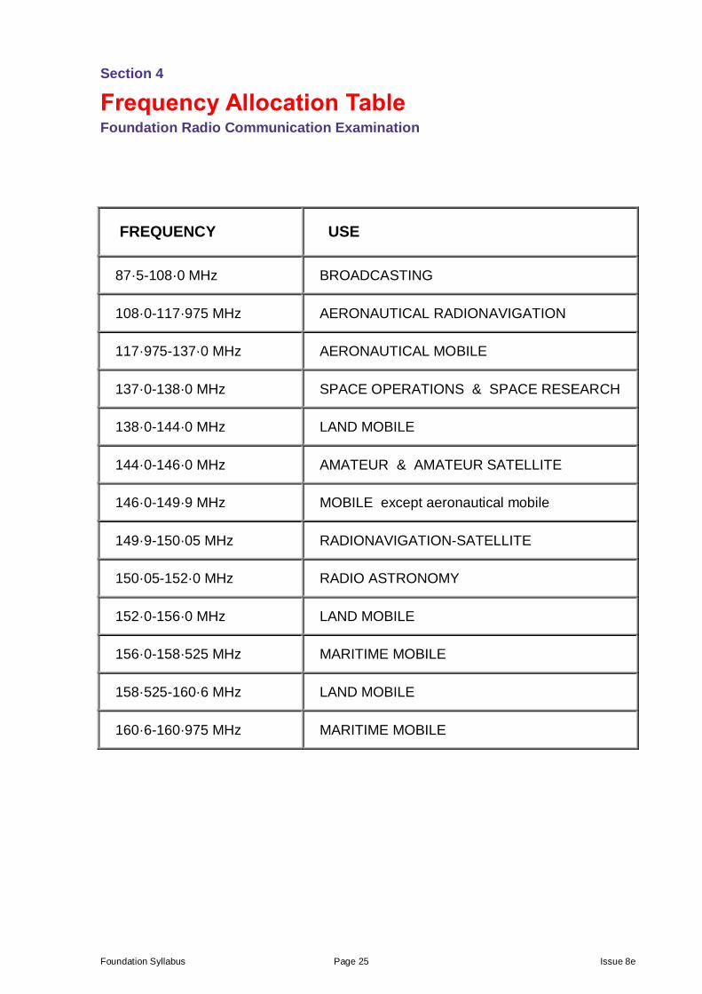
Section 4
Frequency Allocation Table Foundation Radio Communication Examination
FREQUENCY USE
87·5-108·0 MHz BROADCASTING
108·0-117·975 MHz AERONAUTICAL RADIONAVIGATION
117·975-137·0 MHz AERONAUTICAL MOBILE
137·0-138·0 MHz SPACE OPERATIONS & SPACE RESEARCH
138·0-144·0 MHz LAND MOBILE
144·0-146·0 MHz AMATEUR & AMATEUR SATELLITE
146·0-149·9 MHz MOBILE except aeronautical mobile
149·9-150·05 MHz RADIONAVIGATION-SATELLITE
150·05-152·0 MHz RADIO ASTRONOMY
152·0-156·0 MHz LAND MOBILE
156·0-158·525 MHz MARITIME MOBILE
158·525-160·6 MHz LAND MOBILE
160·6-160·975 MHz MARITIME MOBILE
Foundation Syllabus Page 26 Issue 8e
Section 5
Frequency to Wavelength Conversion Chart Foundation Radio Communication Examination
200
300
20
100
40
60
80
2
10
4
6
8
0.3
1.0
0.4
0.6
0.8
10 100 1000
Frequency f(MHz)
Conversion chart Frequency to Wavelength
2 4 6 8 20 40 60 80 200 400 600
Wave
leng
th
(m
)
Note: A larger version will be provided in the examination.