foundation reports for bridges - dot.ca.gov€¦ · foundation reports . for . bridges . february...
TRANSCRIPT

FOUNDATION REPORTS for
BRIDGES
February 2017.r1
DIVISION OF ENGINEERING SERVICES GEOTECHNICAL SERVICES
Foundation Reports for Bridges February 2017.r1
- i -
TABLE OF CONTENTS
1. INTRODUCTION ................................................................................................ 2 1.1 Intent of this Document ..................................................................................................... 2 1.2 Exceptions to Policy .......................................................................................................... 2 1.3 Overview of the Foundation Investigation and Reporting Process ................................... 2 1.4 Signing and Sealing Requirements .................................................................................... 2 1.5 Report Format .................................................................................................................... 3 1.6 Revised Reports ................................................................................................................. 3 1.7 Report Types...................................................................................................................... 4
2. STRUCTURE PRELIMINARY GEOTECHNICAL REPORT (SPGR) AND PRELIMARY FOUNDATION REPORT (PFR) .............................................. 5
2.1. Scope of Work ................................................................................................................... 5 2.2. Project Description ............................................................................................................ 5 2.3. Exceptions to Policies and Procedures .............................................................................. 6 2.4. Field Investigation ............................................................................................................. 6 2.5. Site Geology and Subsurface Conditions .......................................................................... 6 2.6. Groundwater ...................................................................................................................... 7 2.7. As-built Foundation Data .................................................................................................. 7 2.8. Scour Evaluation................................................................................................................ 8 2.9. Corrosion Evaluation ......................................................................................................... 8 2.10. Preliminary Seismic Information and Recommendations ................................................. 9 2.11. Preliminary Foundation Recommendations .................................................................... 11 2.12. Additional Field Work and Laboratory Testing .............................................................. 11 2.13. Report Copy List ............................................................................................................. 12 2.14. Appendices ...................................................................................................................... 12
3. FOUNDATION REPORT (FR) .........................................................................13 3.1. Scope of Work ................................................................................................................. 13 3.2. Project Description .......................................................................................................... 13 3.3. Exceptions to Policies and Procedures ............................................................................ 14 3.4. Field Investigation and Field Testing Program ............................................................... 14 3.5. Laboratory Testing Program ............................................................................................ 14 3.6. Site Geology and Subsurface Conditions ........................................................................ 14 3.7. Groundwater .................................................................................................................... 15 3.8. As-built Foundation Data ................................................................................................ 16 3.9. Scour Evaluation.............................................................................................................. 16 3.10. Corrosion Evaluation ....................................................................................................... 16 3.11. Seismic Design Information and Recommendations....................................................... 16 3.12. Foundation Recommendations ........................................................................................ 17 3.13. Additional Considerations ............................................................................................... 34 3.14. Supplemental Project Information ................................................................................... 34 3.15. Report Copy List ............................................................................................................. 34 3.16. Appendices ...................................................................................................................... 35

Foundation Reports for Bridges February 2017.r1
2
1. INTRODUCTION
1.1 Intent of this Document The intent of this document is to define the Department’s standard of practice for preparation of the Structures Preliminary Geotechnical Report (SPGR), the Preliminary Foundation Report (PFR) and the Foundation Report (FR). Standardized and consistent report presentations for projects statewide benefit the Department’s staff, engineering consultants, bidders, and contractors. Geotechnical Services staff as well as any other organization preparing these reports must comply with the requirements presented herein. This document addresses report content only, it does not address foundation engineering practice (investigations, design procedures, etc.). Policy and procedures relating to foundation investigations and design procedures are presented elsewhere in the Geotechnical Manual. The following terms, as defined below, are used throughout this document to convey the Department’s policy:
Term Definition
Must, Required Mandatory Standard. The associated provisions shall be used. There is no acceptable alternative.
Should Advisory Standard. The associated provisions are preferred practices.
1.2 Exceptions to Policy
Exceptions to the policy and procedures set forth in this document require prior approval per the Offices of Geotechnical Design – Quality Management Plan.
1.3 Overview of the Foundation Investigation and Reporting Process Foundation investigation and reporting generally occurs at three stages of the project development process:
• A Structures Preliminary Geotechnical Report (SPGR) to support Advanced Planning Studies, performed during the WBS 150.15.30 (K Phase) or the 160.10.85 (0 Phase).
• A Preliminary Foundation Report (PFR) to support Type Selection, performed during the WBS 240.65 (1 Phase). (Note: Implementation of 0-Phase drilling will move the PFR to the WBS 160.10 level)
• A Foundation Report (FR) to support the design and construction of the bridge, performed during the WBS 240.80 (1 Phase).
1.4 Signing and Sealing Requirements
Signing and sealing requirements are presented in the Communications and Reporting section of the Offices of Geotechnical Design – Quality Management Plan.
Foundation Reports for Bridges February 2017.r1
3
1.5 Report Format
A separate foundation report must be prepared for each bridge, except that left, center, and/or right bridges with the same bridge number should be combined.
1.5.1 Reports Prepared by Caltrans Staff Foundation Reports are written to the Structure Designer, Specification Engineer, and Structure Construction. They are also provided to bidders via the Information Handout. For reports prepared by Geotechnical Services staff, Foundation Reports must be prepared using the current departmental memorandum format with the subject line of “Foundation Report for Bridge Name” or “Preliminary Foundation Report for Bridge Name” or “Structures Preliminary Geotechnical Report for Bridge Name”. Do not use the section numbers in the report. Section titles must be used. The Log of Test Borings (LOTB) and/or As-built LOTB are not to be submitted as part of the FR. Microstation LOTB files and scanned copies of the As-built LOTB sheets will be sent to the Structure Designer for inclusion within the Contract Plans.
1.5.2 Reports Prepared by Consultants Foundation Reports must consist of the following: cover sheet, table of contents, main contents per this document, and appendices. The cover of the report and any addenda/amendments to the report must include the following information: Caltrans District, County, Route, Post Mile, Bridge Number, Bridge Name, and Expenditure Authorization (EA) number. The LOTB and/or As-built LOTB must be submitted as part of the FR. Refer to the Caltrans Soil and Rock Logging, Classification, and Presentation Manual for direction on the preparation of the LOTB and As-built LOTB.
1.6 Revised Reports When reissuing a report to provide modified recommendations, begin the memorandum subject line with “Revised”, such as “Revised Foundation Report for Little Creek Bridge.” Revised reports are issued as complete reports that supersede all previous versions so that only one report is included in the construction contract. Include a statement in the Scope of Work section of the report to indicate that the revised report supersedes all previous versions. A brief explanation of why the revisions are necessary, and perhaps the scope of revisions, should be included.

Foundation Reports for Bridges February 2017.r1
4
1.7 Report Types 1.7.1 Structure Preliminary Geotechnical Report (SPGR)
The SPGR is required during the early stages of a project to assist Structure Design in the preparation of an Advanced Planning Study and cost estimate for the District. Often the number, location, and type of bridge(s) are not completely known. As a result, recommendations may be general, and detailed field investigations are usually not warranted. Typical fieldwork consists of a site visit only. The SPGR provides an overview of the existing foundations, site geology, seismicity, and, if possible, recommendations regarding suitable and unsuitable foundation types. If appropriate, the SPGR should also discuss the anticipated field and laboratory work required to support the PFR and FR.
1.7.2 Preliminary Foundation Report (PFR) The PFR is required during the early stages of a project after completion of the SPGR and Advanced Planning Study, and prior to the Structure Type Selection. Generally more will be known about the number, location, and types of bridge(s), and the PFR is used to expand upon the information provided in the SPGR. The PFR will document existing foundation conditions, provide preliminary seismic recommendations, make preliminary foundation recommendations, and identify the need for additional investigations and studies. Typically fieldwork will be limited to surficial observations, mapping, and/or measurements, although in certain cases may involve subsurface exploration. For 0-Phase drilling, the above paragraph is revised to: Caltrans is transitioning the subsurface investigation from the 1-phase to the 0-phase. For projects where the subsurface investigation is performed during the 0-phase, the PFR is prepared using the Foundation Report preparation requirements (Section 3) and utilizes the information collected during the subsurface exploration to present draft foundation recommendations based upon preliminary loads provided by Structure Design. The PFR is provided to Structure Design prior to PA&ED and structure type selection.
1.7.3 Foundation Report (FR) The FR expands on data provided in the PFR, documents the results of field exploration and laboratory testing and provides foundation and construction recommendations. The FR becomes part of the contract documents via its inclusion in the Information Handout per Standard Special Provision 2-1.06B, “Supplemental Project Information.” For 0-Phase drilling, the above paragraph is revised to: The FR expands on data provided in the PFR, and updates the foundation recommendations based upon final loads provided by Structure Design. The FR becomes part of the contract documents via its inclusion in the Information Handout per Standard Special Provision 2-1.06B, “Supplemental Project Information.”

Foundation Reports for Bridges February 2017.r1
5
2. STRUCTURE PRELIMINARY GEOTECHNICAL REPORT (SPGR) AND PRELIMARY FOUNDATION REPORT (PFR)
The following topics should be addressed in all Structure Preliminary Geotechnical Reports (SPGR) and Preliminary Foundation Reports (PFR). It is expected that as the foundation investigation process proceeds, the level of detail in the PFR will expand upon the content of the SPGR. If the subsurface investigation (partial or complete) was performed in the 0-phase, prepare the PFR using the applicable portions of the Foundation Report requirements in Section 3, and include “Additional Field Work and Laboratory Testing” as necessary. Example text is italicized and appears at the bottom of most sections.
2.1. Scope of Work
Summarize the purpose, scope, and types of work performed to obtain the information supporting the preliminary recommendations. Reference the general plan and foundation plan by date so the reader knows on what plans the recommendations are based. Do not present an exhaustive list of tasks performed, a few sentences are sufficient. Example Per the request dated January 3, 2017, this Preliminary Foundation Report has been prepared for the proposed widening of Dry Creek Bridge. The purpose of this report is to summarize the preliminary investigations performed and to provide preliminary foundation recommendations for Dry Creek Bridge. The recommendations presented in this report are based on the draft general and foundation plans dated December 15, 2016, review of As-built plans, discussions with Maintenance personnel, and a site visit.
2.2. Project Description Describe the existing and/or proposed bridge(s), and pertinent project information relating to the planned improvements. Provide project datum reference. Example The bridge site is located in the city of San Diego on State Route 15 at PM R3.8 which crosses over Interstate 805 (I-805) at PM 15.1. At this site, the proposed bridge replacement is necessary to accommodate the underlying highway improvements, which include the widening of the existing I-805 in order to provide additional High-Occupancy Vehicle (HOV) lanes. Based on the General Plan (dated December 10, 2015), the proposed bridge is a 2-span, cast-in-place, prestressed concrete box girder bridge supported on pile foundations. All elevations referenced within this report are based on the National Geodetic Vertical Datum of 1929 (NGVD 29), unless otherwise noted.

Foundation Reports for Bridges February 2017.r1
6
2.3. Exceptions to Policies and Procedures If applicable, discuss exceptions to Departmental policies and procedures relating to the SPGR or PFR. Approved Request for Exception forms must be included in the Appendix.
2.4. Field Investigation Provide an overview of the field investigation(s) to support the preliminary foundation recommendations. Example As-built LOTB show that a subsurface investigation, consisting of three mud rotary borings, was performed in 1969. Additionally, a site visit was performed on February 23, 2016.
2.5. Site Geology and Subsurface Conditions Provide a generalized description of the project site geology and known subsurface conditions. The site data may come from current or past field investigations at or near the bridge site, As-built LOTB, maintenance records, construction notes, geologic literature, or any other relevant information. The information included within this section may include but not be limited to:
• Pertinent observations from the site visit • Topography and geology • Types of soil and thickness of generalized layers • Type of rock and depth to rock • Pertinent soil conditions or geologic hazards, such as
o Landslides or slope failures o Embankment failures o Unsuitable materials (Collapsible, expansive foundation materials)
Do not re-create the As-built LOTB in detail in this section. A generalized discussion is sufficient. Example The bridge is located within the Peninsular Range Geomorphic Province of California. The Geologic Map of Santa Ana 30’ x 60’ Quadrangle shows that the site is underlain by Quaternary alluvium. The topography is relatively flat and the site appears free of geologic hazards. In general, the alluvial soil at the site can be separated into three units. The upper unit consists of very loose to slightly compact silty sand with gravel that extends from the ground surface to a depth of about 15 feet (~ Elev. 950 feet). The middle unit consists of slightly compact to dense sand to a depth of approximately 35 feet (~ Elev. 930 feet). The lowermost unit consists of dense to very dense gravelly sand and sandy gravel with isolated zones of sandy silt and gravel. This unit extends to the maximum explored depth of the borings, which is approximately 60 feet below the ground surface (~ Elev. 905 feet).

Foundation Reports for Bridges February 2017.r1
7
2.6. Groundwater
Report groundwater elevation(s) and dates of measurements. Use of a table is recommended if there are numerous borings and/or measurements. Example: Groundwater Present During the 1966 subsurface investigation, groundwater was encountered in both borings. Groundwater levels varied from elevation 945 feet in February to elevation 938 feet in August. Recent measurements by the Department of Water Resources for nearby sites are generally consistent with the 1966 measurements. Example: Groundwater Not Present During the 1966 subsurface investigation, groundwater was not encountered in either boring within the explored depth of 100 feet (elevation 900 feet). Example: Groundwater Information Not Available Groundwater information was not available based upon the literature search performed.
2.7. As-built Foundation Data Include discussion of relevant As-built data, such as:
• Existing foundation types • As-built geotechnical capacities or resistances • Construction reports or records such as pile driving logs, pile load test reports,
groundwater monitoring notes, etc. Example: Driven Piles Construction of the original bridge was completed in 1969 with all three supports supported on driven Alternative (Alt) “X” concrete piles with a design load of 45 tons. The 1969 As-built LOTB provided some pile driving information, which included the minimum, average, and maximum penetration elevations for the piles. The bottom of pile cap elevations listed were obtained from the as-built foundation plan. Table 1 presents a summary of the 1969 As-built Data.
Table 1: Summary of the 1969 As-built Data
Support Location
Foundation Type
Design Load
Bottom of Pile Cap Elev. (ft)
Min. Penetration
Elev. (ft)
Avg. Penetration
Elev. (ft)
Max Penetration
Elev. (ft)
Abut 1 12” Driven Alt “X” Pile 45 ton 958.1 929.3 927.1 926.5
Bent 2 12” Driven Alt “X” Pile 45 ton 935.5 920.2 918.1 916.1
Abut 3 12” Driven Alt “X” Pile 45 ton 953.6 928.1 926.5 925.3
Foundation Reports for Bridges February 2017.r1
8
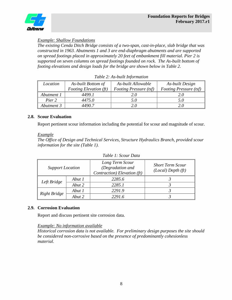
Example: Shallow Foundations The existing Cenda Ditch Bridge consists of a two-span, cast-in-place, slab bridge that was constructed in 1963. Abutments 1 and 3 are end-diaphragm abutments and are supported on spread footings placed in approximately 20 feet of embankment fill material. Pier 2 is supported on seven columns on spread footings founded on rock. The As-built bottom of footing elevations and design loads for the bridge are shown below in Table 2.
Table 2: As-built Information Location As-built Bottom of
Footing Elevation (ft) As-built Allowable
Footing Pressure (tsf) As-built Design
Footing Pressure (tsf) Abutment 1 4499.1 2.0 2.0
Pier 2 4475.0 5.0 5.0 Abutment 3 4490.7 2.0 2.0
2.8. Scour Evaluation
Report pertinent scour information including the potential for scour and magnitude of scour. Example The Office of Design and Technical Services, Structure Hydraulics Branch, provided scour information for the site (Table 1).
Table 1: Scour Data
Support Location Long Term Scour (Degradation and
Contraction) Elevation (ft)
Short Term Scour (Local) Depth (ft)
Left Bridge Abut 1 2285.6 3 Abut 2 2285.1 3
Right Bridge Abut 1 2291.9 3 Abut 2 2291.6 3
2.9. Corrosion Evaluation
Report and discuss pertinent site corrosion data. Example: No information available Historical corrosion data is not available. For preliminary design purposes the site should be considered non-corrosive based on the presence of predominantly cohesionless material.

Foundation Reports for Bridges February 2017.r1
9
Example: Non-Corrosive Three soil samples and one water sample were collected for corrosion testing during the 2016 subsurface investigation. Corrosion test results for those samples are shown below in Table 1. Based on current Caltrans’ standards, the site is considered to be non-corrosive. Example: Corrosive During the 2016 subsurface investigation four soil samples were collected for corrosion testing. Corrosion test results for the samples collected from borings RC-16-001 and RC-16-010 are shown below in Table 1. Due to chloride content being greater than 500 ppm in two of the samples tested, the site is considered to be corrosive based on current Caltrans’ standards, and corrosion mitigation is required.
Table 1: Soil Corrosion Test Summary
Boring ID Elevation (ft) Minimum Resistivity (Ohm-Cm)
pH Chloride Content (ppm)
Sulfate Content (ppm)
RC-16-001 15.8 to 14.3 1544 7.24 N/A N/A
RC-16-001 -4.2 to -3.2 683 7.94 384 432
RC-16-010 -69.1 to -70.6 73 6.86 850 1500
RC-16-010 -104.1 to -105.6 78 7.71 1000 1600 Caltrans currently defines a corrosive environment as an area where the soil has either a chloride concentration of 500 ppm or greater, a sulfate concentration of 2000 ppm or greater, or has a pH of 5.5 or less. With the exception of MSE walls, soil and water are not tested for chlorides and sulfates if the minimum resistivity is greater than 1,000 ohm-cm.
2.10. Preliminary Seismic Information and Recommendations The preliminary seismic information and recommendations must include:
1. VS30 and how it was estimated (e.g., SPT correlations, Seismic CPT, PS Logging). 2. Peak ground acceleration (PGA) at the site. 3. Maximum moment magnitude (MMax) and site-to-fault distance (RRUP) if
deterministic. Design magnitude (M) and site-to-fault distance if probabilistic. 4. Identify site and/or support locations as either “Poor, Marginal, or Competent” per
the Caltrans Seismic Design Criteria (SDC), “Classification of Soils.” a. 0-Phase drilling: provide p-y curves if site soils are “Poor” or “Marginal.”
5. Seismic Design Data Sheet (use attached template) 6. If applicable:
a. Surface fault rupture potential (see Fault Rupture Module) b. Liquefaction potential (see Liquefaction Evaluation Module) c. Lateral spreading potential d. Seismically induced settlement e. Seismic slope instability f. Tsunami risk
Foundation Reports for Bridges February 2017.r1
10
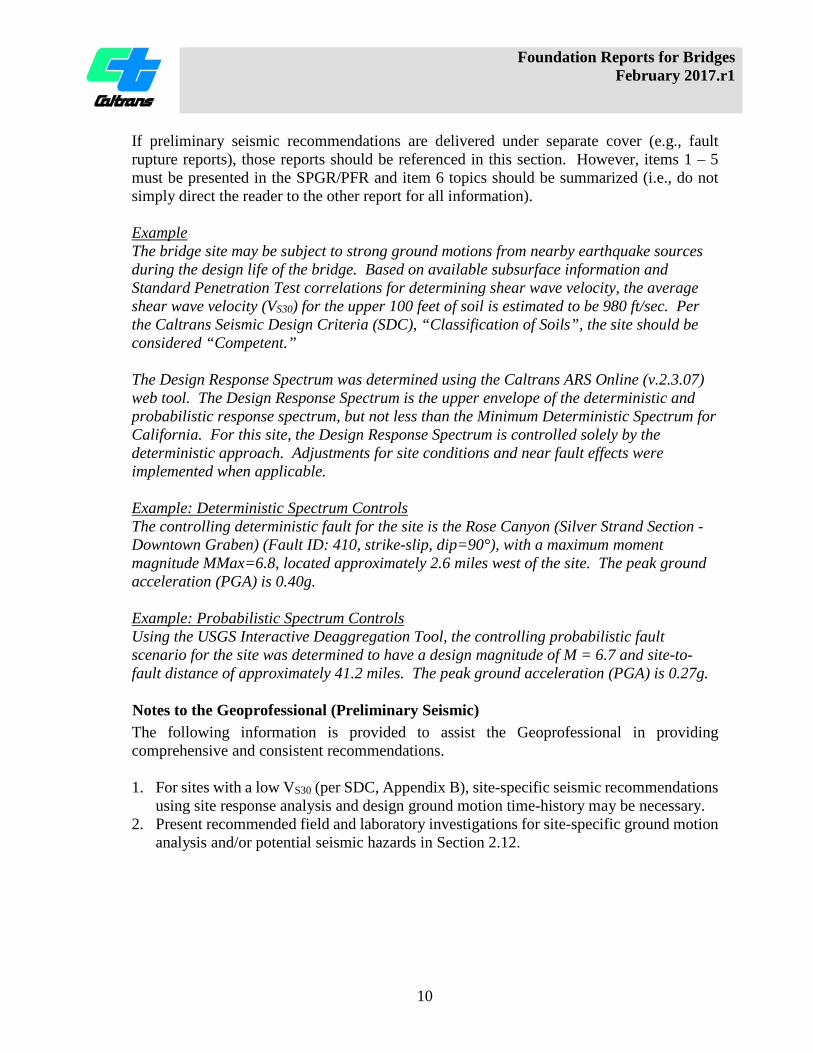
If preliminary seismic recommendations are delivered under separate cover (e.g., fault rupture reports), those reports should be referenced in this section. However, items 1 – 5 must be presented in the SPGR/PFR and item 6 topics should be summarized (i.e., do not simply direct the reader to the other report for all information). Example The bridge site may be subject to strong ground motions from nearby earthquake sources during the design life of the bridge. Based on available subsurface information and Standard Penetration Test correlations for determining shear wave velocity, the average shear wave velocity (VS30) for the upper 100 feet of soil is estimated to be 980 ft/sec. Per the Caltrans Seismic Design Criteria (SDC), “Classification of Soils”, the site should be considered “Competent.” The Design Response Spectrum was determined using the Caltrans ARS Online (v.2.3.07) web tool. The Design Response Spectrum is the upper envelope of the deterministic and probabilistic response spectrum, but not less than the Minimum Deterministic Spectrum for California. For this site, the Design Response Spectrum is controlled solely by the deterministic approach. Adjustments for site conditions and near fault effects were implemented when applicable. Example: Deterministic Spectrum Controls The controlling deterministic fault for the site is the Rose Canyon (Silver Strand Section - Downtown Graben) (Fault ID: 410, strike-slip, dip=90°), with a maximum moment magnitude MMax=6.8, located approximately 2.6 miles west of the site. The peak ground acceleration (PGA) is 0.40g. Example: Probabilistic Spectrum Controls Using the USGS Interactive Deaggregation Tool, the controlling probabilistic fault scenario for the site was determined to have a design magnitude of M = 6.7 and site-to-fault distance of approximately 41.2 miles. The peak ground acceleration (PGA) is 0.27g.
Notes to the Geoprofessional (Preliminary Seismic) The following information is provided to assist the Geoprofessional in providing comprehensive and consistent recommendations. 1. For sites with a low VS30 (per SDC, Appendix B), site-specific seismic recommendations
using site response analysis and design ground motion time-history may be necessary. 2. Present recommended field and laboratory investigations for site-specific ground motion
analysis and/or potential seismic hazards in Section 2.12.
Foundation Reports for Bridges February 2017.r1
11
2.11. Preliminary Foundation Recommendations
Recommendations must include discussion on the appropriateness of shallow foundations, driven pile foundations, and cast-in-drilled-hole (CIDH) concrete piles. Recommendations must be presented in the order of preference with the recommended foundation type(s) presented first; followed by feasible, but not preferred, alternatives; followed by foundation types not recommended. If applicable, include commentary relating to foundation types proposed by the Structure Designer (MTD 3-1, Table 3-2). Example At all three support locations, the preferred foundation type is a Standard Plan driven concrete pile as it will generate significant end-bearing resistance in the underlying dense sand layer. If tension and/or lateral resistance requires additional penetration, Steel H-Piles or Standard Plan open-ended steel pipe piles (Alternative “W”) are recommended. CIDH concrete piles are not recommended due to the presence of groundwater, construction difficulties, and increased costs associated with potential caving soil. Shallow foundations are not recommended due to the presence of loose near-surface compressible soil.
2.12. Additional Field Work and Laboratory Testing Describe the anticipated scope and types of fieldwork and testing that may be required to complete the foundation investigation. Discuss the potential need for entry permits, task orders, groundwater monitoring, access road construction, lane closures, etc. Example: SPGR The available site information will not provide adequate data to complete the design recommendations for Dry Creek Bridge. Therefore, a field investigation consisting of approximately four borings and laboratory testing will be performed to characterize the site. To achieve the goal of 0-Phase drilling, the District Project Manager must initiate the process of obtaining drilling clearances (e.g., environmental permits, right of entry, categorical exemptions, etc.) so that drilling, preliminary design, and the Preliminary Foundation Report can be completed prior to the end of PA&ED. For foundation investigation details, the District Project Manager may contact the Office of Geotechnical Design XX. The request for the Preliminary Foundation Report should conform to “Memo to Designers” 1-35 and include all design information for Foundation Recommendations (per MTD 3-1 and/or MTD 4-1). The request should include a General Plan and preliminary foundation loads so the number, depth, and location of borings can be determined.
Foundation Reports for Bridges February 2017.r1
12
If soil-structure interaction analysis data such as p-y, t-z and q-z curves are required, indicate that in the request. If the current vertical datum that will be used for the proposed bridge is different than the As-built datum, then a datum conversion needs to be provided. Any questions regarding the above recommendations should be directed to the attention of NAME and PHONE.
2.13. Report Copy List The SPGR and PFR must be addressed to the Structure Designer and copies provided to those listed under Report Distribution in the Communications and Reporting Module.
2.14. Appendices Appendix I: Seismic Design Data Sheet
Foundation Reports for Bridges February 2017.r1
13
3. FOUNDATION REPORT (FR) The following topics, if applicable, must be addressed in the Foundation Report.
3.1. Scope of Work
Summarize the scope and types of work performed to obtain the information supporting the foundation recommendations. Include a statement that the current report supercedes all previous reports (referenced by title and date). Example: Foundation Report Per the request dated January 10, 2017, this Foundation Report has been prepared for the proposed widening of Dry Creek Bridge. The purpose of this report is to summarize the investigations performed and to provide foundation recommendations for Dry Creek Bridge. The recommendations presented in this report are based on the general and foundation plans dated December 10, 2016, a subsurface investigation, loads and scour information provided by Structure Design. This Foundation Report supercedes the Preliminary Foundation Report for Dry Creek Bridge dated March 15, 2016 and the Structure Preliminary Geotechnical Report for Dry Creek Bridge dated January 28, 2016. Example: Preliminary Foundation Report with 0-Phase Drilling Per the request dated January 10, 2017, this Preliminary Foundation Report has been prepared for the proposed widening of Dry Creek Bridge. The purpose of this report is to summarize the investigations performed and to provide preliminary foundation recommendations for Dry Creek Bridge. The recommendations presented in this report are based on the draft general plan dated December 10, 2016, a subsurface investigation consisting of borings at the abutments, and preliminary loads and scour information provided by Structure Design. Borings were not completed at Bent 2 because access permits were not yet available.
3.2. Project Description Describe the existing and/or proposed bridge(s), and pertinent project information relating to the planned foundation improvements. The datum used to reference the elevations in the report should be included. Example The bridge site is located in the city of San Diego on State Route 15 at PM R3.8 which crosses over Interstate 805 (I-805) at PM 15.1. At this site, the proposed bridge replacement is necessary to accommodate the underlying highway improvements, which include the widening of the existing I-805 in order to provide additional High-Occupancy Vehicle (HOV) lanes. All elevations referenced within this report are based on the North American Vertical Datum of 1988 (NAVD 88), unless otherwise noted. To convert an

Foundation Reports for Bridges February 2017.r1
14
elevation at this site from National Geodetic Vertical Datum of 1929 (NGVD 29) to NAVD 88, add 2.3 feet to the NGVD 29 elevation. Based on the General Plan (dated December 10, 2015), the proposed bridge is a 2-span, cast-in-place, prestressed concrete box girder bridge supported on pile foundations.
3.3. Exceptions to Policies and Procedures Discuss exceptions to Departmental policies and procedures relating to the FR. Approved Request for Exception forms must be included in the Appendix.
3.4. Field Investigation and Field Testing Program Provide an overview of the field investigation(s) performed to support the foundation recommendations including the number of boreholes/CPT soundings, and geophysical testing. Example In May 2016, a subsurface investigation was performed consisting of three mud rotary borings drilled to a maximum depth of 80 feet. Additionally, the As-built LOTB indicates that three borings were drilled to a maximum depth of 45 feet in 1969.
3.5. Laboratory Testing Program Provide an overview of the laboratory testing program, if performed, to support the foundation recommendations. Briefly explain what the tests were used for (e.g. soil classification, settlement, strength parameters). Example During the most recent field investigation, soil samples for particle analysis and Atterburg limits were collected from borings RC-16-001 through RC-16-002 for soil classification and liquefaction evaluation. The summary of the results will be provided in the Information Handout (referenced in the Special Provisions, Supplemental Project Information section), and the test sample locations will be shown on the Log of Test Borings.
3.6. Site Geology and Subsurface Conditions Based on the field investigation, provide an updated generalized description of the project site geology and known subsurface conditions. Do not re-create the As-built LOTB in detail in this section. A generalized discussion is sufficient. Present only factual information in this section, not how it relates to design and construction. Discussion of the site geology, geological features, and subsurface conditions as they relate to the foundation design and construction must be placed in the Foundation Recommendations and Construction Considerations sections, respectively.

Foundation Reports for Bridges February 2017.r1
15
Example The bridge site is located within the Mojave Desert Geomorphic Province of California. The “Geologic Map of the San Bernardino Quadrangle” (Bortugno and Spittler, 1998) shows that the bridge site is underlain by Quaternary alluvium. During the 2015 investigation, boring RC-15-001 was drilled near the right bridge Abutment 2 location, boring RC-15-002 was drilled near the left bridge Abutment 2 location, boring RW-15-003 was drilled near the left bridge Abutment 1 location, and boring RW-15-004 was drilled near the right bridge Abutment 1 location. The soil borings revealed that the site is underlain by interbedded layers of predominantly dense to very dense poorly-graded sand with silt and well-graded sand with gravel, cobbles, and boulders, to the maximum depth drilled at the site of 80.9 feet (elev. 2377.9 feet). Soil descriptions from the 2015 subsurface investigation are presented on the Log of Test Borings. At Abutment 2 (Boring RC-15-002), very hard boulders up to 4 feet in size were identified, however, larger boulders up to 8 feet were visible in the adjacent exposed slope.
3.7. Groundwater Report groundwater elevation(s) and dates of measurements. Use of a table is recommended if there are numerous borings and/or measurements. Include discussions relating to the presence of wet or saturated soil when groundwater measurements were not made. Discuss surface water conditions that might influence the design or construction of the foundations. State the groundwater elevation(s) used for analyses and design. Example As-built LOTB’s from the April 1968 subsurface investigation indicate that groundwater was encountered in several borings at that time, and ranged from elevation 19.0 feet to elevation 21.2 feet (NAVD88 datum). During the 2010 subsurface investigation groundwater was measured in Boring R-10-001 at elevation 15.3 feet, and in Boring R-10-002 at elevation 13.9 feet. During the 2014/2015 subsurface investigation, ground water was encountered in the borings and was measured in boring R-15-003 at elevation 17.1 feet, which corresponded to the level of the water in the riverbed at that time. The groundwater elevation used for design was 21 feet. Example: Perched Groundwater During the 2016 subsurface investigation top of groundwater was measured to be about 6 feet above the sedimentary rock in both Boring RC-16-001 (Abutment 1) and RC-16-002 (Abutment 2). Given that the top of rock at Abutment 1 is at elevation 20 feet and elevation 5 feet at Abutment 2, the groundwater is considered to be perched on top of the sloping rock.
Foundation Reports for Bridges February 2017.r1
16
3.8. As-built Foundation Data If not addressed elsewhere in the FR, include discussion of relevant As-built data, such as pile driving logs, pile load test reports, groundwater monitoring notes, etc.
3.9. Scour Evaluation Reference and summarize the hydraulic findings outlined in the hydraulics report. Note to Geoprofessional: If the field investigation reveals geologic information that contradicts the hydraulics report, then the Geoprofessional must discuss the findings in the FR and provide that information to author of the hydraulics report so that the scour recommendations can be re-evaluated.
3.10. Corrosion Evaluation Include and update the corrosion data required for the PFR (Section 2.9) based on new findings and field investigations. If corrosion testing was not completed during the foundation investigation, provide justification for the corrosion recommendations.
3.11. Seismic Design Information and Recommendations Include and update the seismic design information required for the PFR (Section 2.10) based on new findings and field investigations. Provide seismic design recommendations for the proposed foundations (e.g., liquefaction mitigation, p-y, t-z curves, fault rupture evaluation, etc.). If requested, the seismic design information should also include seismic earth pressure behind the wall/abutments. Example: Liquefaction The Seismic Design Recommendations report, dated 12/16/2016, states that due to the presence of loose to medium dense alluvial material and high ground water beneath the site, the potential for soil liquefaction under strong ground shaking is present at the site. Table 2, below, presents the liquefiable zone elevations at the abutment and pier locations.
Table 2: Liquefaction Potential at Old River Bridge
Support Liquefaction Elevation (ft) Estimated Seismic-induced Settlement (in)
Abutment 1 Elev. 20 to 15
and Elev. 0 to -5
3
Pier 2 Elev. 10 to -5 4 Abutment 3 Elev. 20 to 10 3
Foundation Reports for Bridges February 2017.r1
17
Example: Lateral Spreading Potential The Seismic Design Recommendations report, dated 12/16/2016, states that it is anticipated that lateral spreading may occur at Abutments 1 and 6 locations. The lateral spreading forces at the top of each pile are estimated to be 130 kips at Abutment 1, and 120 kips at Abutment 6. See the Seismic Design Recommendations report for additional information. Example: Seismic Settlement The Seismic Design Recommendations report, dated 12/16/2016, states that liquefaction-induced settlement of the ground surface is estimated to range from 3 to 5 inches. See the Seismic Design Recommendations report for additional information regarding settlement for the existing bridge.
3.12. Foundation Recommendations
Provide complete and concise foundation recommendations by addressing the topics in the applicable portions of this section. Discuss the recommended foundations and any special considerations which influence their design and selection (ground improvement, scour, liquefaction, usage of casings or shells, etc.). Example: Shallow Foundations The following recommendations are for the proposed Dry Creek Bridge (Br. No. 54-1200), as shown on the General Plan dated March 14, 2016. At Abutments 1 and 2 support locations, spread footings are recommended. The subsurface information gathered for the site indicate that the abutment footings will be founded in sedimentary rock formation. The following foundation recommendations were designed in accordance with the 2014 AASHTO LRFD Bridge Design Specification (6th Edition) with CA Amendments. Example: Deep Foundations The following recommendations are for the proposed Wet Creek Bridge (Br. No. 54-1201), as shown on the General Plan dated March 18, 2016. Based on the subsurface information gathered at the site, driven precast concrete piles are recommended at the abutments and CIDH concrete piles are recommended at Pier 2. The following foundation recommendations were designed in accordance with the 2014 AASHTO LRFD Bridge Design Specification (6th Edition) with CA Amendments.
3.12.1 Shallow Foundations Present and/or discuss the following:
1. A description of the material on which the footing is to be placed. 2. Summary of controlling loads and footing sizes table (MTD 4-1, Attachment 4,
Tables 3 & 4). 3. Foundation Design Recommendations for Spread Footing table and Spread Footing
Data Table (MTD 4-1, Attachment 5, Tables 2 & 3). 4. Calculated resistance factor for overall global stability and local slope stability
(Service Limit State and Extreme Event Limit State).

Foundation Reports for Bridges February 2017.r1
18
5. The influence of construction of the new footing on the adjacent structures and/or utilities, if applicable.
Notes to the Structure Designer (Shallow Foundations) Provide the following (applicable) information in this section to aid in preparation of the contract plans. 1. Spread Footings below groundwater level: Identify the type of excavation (Type A or
Type D) required at all applicable support locations (See Bridge Design Aids, Section 11 - Estimating).
Example Groundwater will be encountered during construction of the footings at the proposed abutment, therefore show Structure Excavation Type D on the plans.
2. Spread footings with sub-excavation and replacement with structure backfill.
Example At the Abutment 1 & 4 support locations, unsuitable native soils were identified in the subsurface investigation and possibly underlie the proposed footing. Therefore, it is recommended that the native materials be removed to a depth of XX feet below the bottom of footing, and be replaced with structure backfill compacted to 95% relative compaction, or concrete to the bottom of footing elevation. The bottom of sub-excavation elevations for the abutments are listed in Table 1. The limits of the sub-excavation and replacement must conform to the limits specified in Standard Specification 19-5.03B for compaction of embankments under retaining wall footings without pile foundations.
Table 1: Abutment 1 & 4 – Bottom of Sub-Excavation Elevation
Support Location Bottom of Sub-Excavation Elevation (ft)
Abutment 1 4334.4 Abutment 4 4336.4
Foundation Reports for Bridges February 2017.r1
19
Construction Considerations (Shallow Foundations) Provide the following (applicable) information in this section for use by the Specification Engineer, Structure Construction Representative, Contractor, and others. 1. Include the following instructions (edited to the project site) to address potential
disturbance of native material below the specified bottom of footing elevation(s).
Example At all support locations, the spread footings are to be constructed on the native alluvium at the bottom of the excavation. The structural concrete is to be placed neat against the undisturbed native alluvium at the bottom of the footing excavation. Should the bottom of the footing excavation be disturbed, then the disturbed material must be removed to a depth of XX feet below the disturbance, and recompacted to 95% relative compaction. Example At all support locations, the spread footings are to be constructed on the weathered rock at the bottom of the excavation. The structural concrete is to be placed neat against the trimmed walls and undisturbed rock at the bottom of the footing excavation. Should the bottom of the footing excavation be disturbed, then the disturbed material must be removed and replaced to the bottom of footing elevation with concrete.
2. Include the following instructions to request footing inspections by the Geoprofessional. Example All support footing excavations are to be inspected and approved by the Office of Geotechnical Design XX, Branch X. The inspections are to be made after the excavation has been completed to the bottom of footing elevations and prior to placing concrete or rebar in the excavations. The contractor is to allow seven working days for the inspection of each footing excavation to be completed. The Structures Representative is to provide the Office of Geotechnical Design XX, Branch X a one-week notification prior to beginning the seven-day contractor waiting period. (Note: If sub-excavation and replacement are to be required, modify the above example to require the inspection to be performed when the contractor completes the sub-excavation and prior to replacement.)

Foundation Reports for Bridges February 2017.r1
20
3.12.2 Deep Foundations (CIDH Concrete Piles)
Present and/or discuss the following: 1. Information provided by Structure Designer
a. Foundation Design Information Sheet (MTD 3-1, Attachment 1, Table 3-4) b. Foundation Factored Design Loads (MTD 3-1, Attachment 1, Table 3-5)
2. Information Provided by Geoprofessional a. Foundation Design Recommendations table and the Pile Data Table (MTD 3-1,
Attachment 1, Tables 3-6 & 3-7 or Tables 3-8 & 3-9), with the following modifications:
i. Modify the tables to report the Nominal Resistance, not Required Factored Nominal Resistance.
ii. Add footnote: “Column heading modified from Required Factored Nominal Resistance to Nominal Resistance.”
iii. Report the resistance factors (in column header) using the appropriate notations, e.g., φqs = XX for side resistance (skin friction), φqp = YY for tip resistance (end bearing), see AASHTO LRFD BDS, CA Amendment 10.3 & 10.5.5.2.4-1.
iv. The Nominal Resistance reported in the Foundation Design Recommendations table and the Pile Data Table must be rounded up to the nearest 10 kips.
v. If a CIDH concrete pile is supporting a single column, identify whether the pile is a Type I or Type II shaft in the Foundation Design Recommendations table (“Pile Type” column).
vi. For Permanent Steel Casing/Driven Steel Shell, a column with the specified tip elevation must be placed in the Foundation Design Recommendations table and the Pile Data Table.
vii. For Rock Socket quantity, the “Top of Rock Socket” column must be placed in the Foundation Design Recommendations table and the Pile Data Table.
viii. Add footnote to define the Bottom of Rock Socket. An example Foundation Design Recommendations table is presented on the following page.

Foundation Reports for Bridges February 2017.r1
21
INSERT FOUNDATION RECOMMENDATION TABLE HERE
Foundation Reports for Bridges February 2017.r1
22
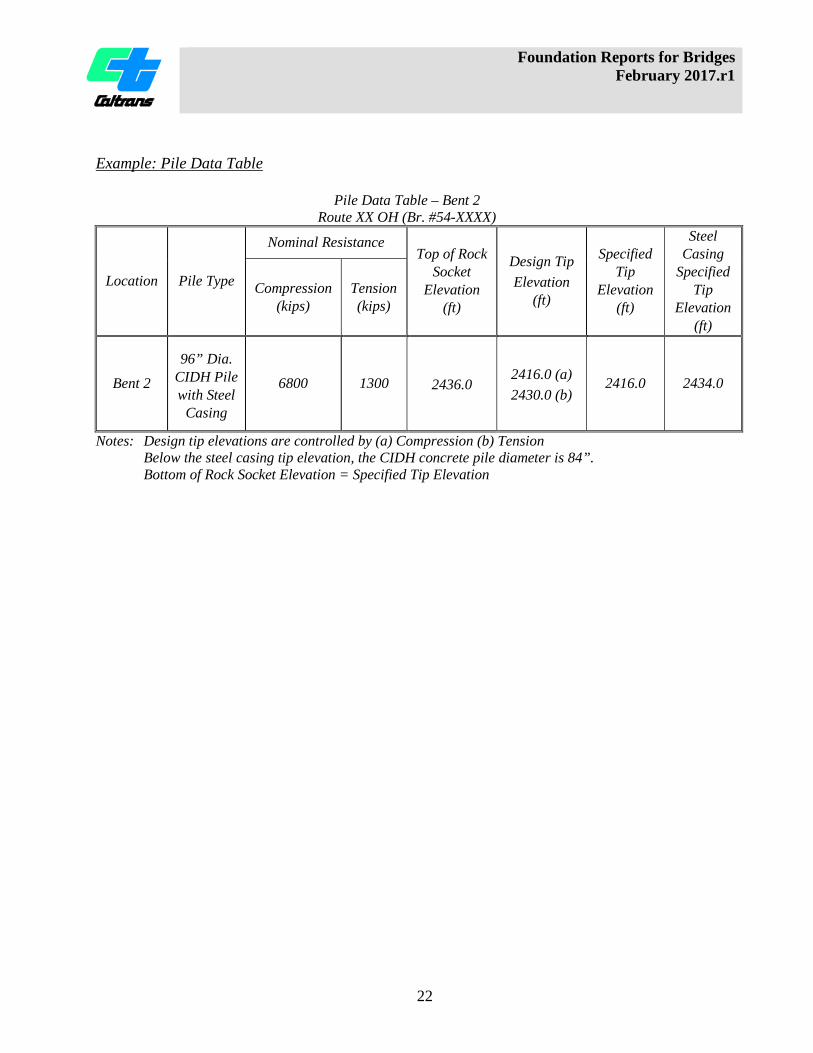
Example: Pile Data Table
Pile Data Table – Bent 2
Route XX OH (Br. #54-XXXX)
Location Pile Type
Nominal Resistance Top of Rock
Socket Elevation
(ft)
Design Tip Elevation
(ft)
Specified Tip
Elevation (ft)
Steel Casing
Specified Tip
Elevation (ft)
Compression (kips)
Tension (kips)
Bent 2
96” Dia. CIDH Pile with Steel
Casing
6800 1300 2436.0 2416.0 (a) 2430.0 (b)
2416.0 2434.0
Notes: Design tip elevations are controlled by (a) Compression (b) Tension Below the steel casing tip elevation, the CIDH concrete pile diameter is 84”. Bottom of Rock Socket Elevation = Specified Tip Elevation

Foundation Reports for Bridges February 2017.r1
23
Notes to the Geoprofessional (CIDH Concrete Piles) The following information is to assist the Geoprofessional in providing comprehensive and consistent recommendations. Some of this information will ultimately be moved to the Deep Foundation Design module of the Geotechnical Manual. 1. Terminology
a. Cast-In-Drilled Hole (CIDH) concrete piles: CIDH concrete piles, also known as drilled shafts, can be used as smaller-diameter piles that are connected to a pile cap supporting a column or as a larger pile (typically 5 feet or larger) that directly supports a column and is either a Type I or Type II shaft (as determined by the Structure Designer). Standard Plan CIDH concrete piles are either 16 or 24 inches in diameter, whereas special design CIDH concrete piles range from 30 to 120 inches in diameter but can be larger if geologic conditions and project needs dictate their use. Piles placed in wet conditions must be at least 24 inches in diameter to accommodate inspection pipes for acceptance testing. CIDH concrete pile lengths should be limited to 30 times the pile diameter to help ensure constructability and quality. Type I/Type II Shaft:
i. Type I Shaft: the reinforcement consists of one continuous cage that extends from the pile tip up to the bent cap.
ii. Type II Shaft: the reinforcement consists of one cage that extends from the pile tip up to the pile cut-off elevation. The column cage is a smaller-diameter cage that extends down into the CIDH concrete pile reinforcement cage to form a lap splice. For 5-foot diameter and larger Type II shaft, a construction joint is mandatory at the bottom of the column rebar cage elevation. The construction joint will require the placement of a permanent steel casing/shell in the hole to allow workers to clean and prepare the joint.
b. Rock Socket: a CIDH concrete pile constructed in hard rock typically requiring a core barrel, cluster hammer or other hard rock tools for excavation. The rock is usually stronger than concrete, however, the side resistance is controlled by the compressive strength of concrete, not the rock strength.
c. Driven Steel Shell: Used for structural capacity and/or geotechnical resistance. Must be driven into place.
d. Permanent Casing can be either: i. Permanent Smooth-wall Steel Casing: Used for constructability. May be used
for structural capacity. Not used for geotechnical resistance. Method of installation dictated in the Foundation Report.
ii. Corrugated Metal Pipe (CMP) Casing: Used for constructability. May be used for geotechnical resistance. Not used for structural capacity. A CMP is placed in an excavated hole and the annular space backfilled with grout (SS 49-3.02B(5), 49-3.02C(6)). If geotechnical resistance of the CMP is utilized in the pile design, limit the skin friction zone to the uppermost 20 feet.
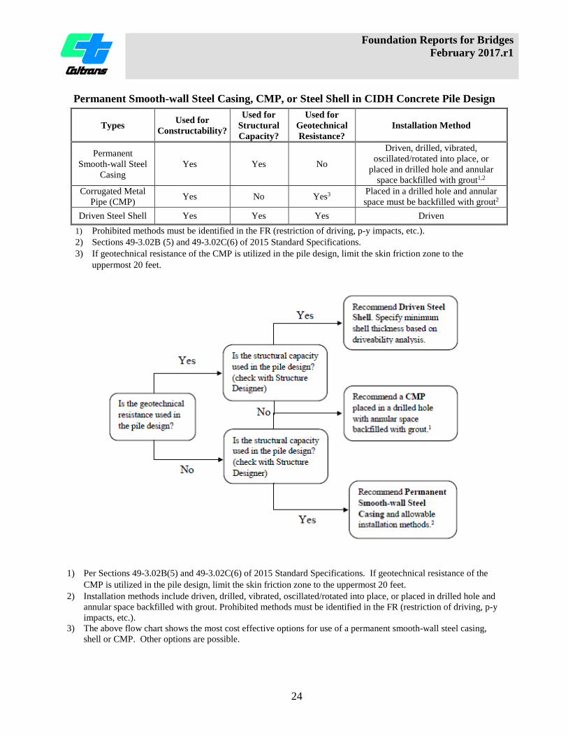
The table and flow chart on the following page presents the options for use of a permanent smooth-wall steel casing, shell, or CMP.
Foundation Reports for Bridges February 2017.r1
24
Permanent Smooth-wall Steel Casing, CMP, or Steel Shell in CIDH Concrete Pile Design
Types Used for Constructability?
Used for Structural Capacity?
Used for Geotechnical Resistance?
Installation Method
Permanent Smooth-wall Steel
Casing Yes Yes No
Driven, drilled, vibrated, oscillated/rotated into place, or
placed in drilled hole and annular space backfilled with grout1,2
Corrugated Metal Pipe (CMP) Yes No Yes3 Placed in a drilled hole and annular
space must be backfilled with grout2 Driven Steel Shell Yes Yes Yes Driven
1) Prohibited methods must be identified in the FR (restriction of driving, p-y impacts, etc.). 2) Sections 49-3.02B (5) and 49-3.02C(6) of 2015 Standard Specifications. 3) If geotechnical resistance of the CMP is utilized in the pile design, limit the skin friction zone to the
uppermost 20 feet.
1) Per Sections 49-3.02B(5) and 49-3.02C(6) of 2015 Standard Specifications. If geotechnical resistance of the
CMP is utilized in the pile design, limit the skin friction zone to the uppermost 20 feet. 2) Installation methods include driven, drilled, vibrated, oscillated/rotated into place, or placed in drilled hole and
annular space backfilled with grout. Prohibited methods must be identified in the FR (restriction of driving, p-y impacts, etc.).
3) The above flow chart shows the most cost effective options for use of a permanent smooth-wall steel casing, shell or CMP. Other options are possible.

Foundation Reports for Bridges February 2017.r1
25
Notes to the Structure Designer (CIDH Concrete Piles) Provide the following (applicable) information in this section to aid in preparation of the contract plans and specifications. 1. Permanent Smooth-wall Steel Casing, Driven Steel Shell, and CMP: The Foundation
Report must state if the resistance of the casing, shell, or CMP is used in pile design, and specify acceptable installation methods. If a CMP is to be utilized, the Geoprofessional must state in the FR that the permanent steel casing be specified as a CMP.
Example The driven steel shell is to be shown on the contract plans. The structural capacity and geotechnical resistance of the driven steel shell were used in the design of the pile. Example The permanent smooth-wall steel casing is to be shown on the contract plans. The structural capacity of the permanent smooth-wall steel casing was used in the design of the pile. The geotechnical resistance of the permanent smooth-wall steel casing was not used in the design of the pile. Installation methods include drilled, oscillated/rotated into place, or placed in drilled hole and annular space backfilled with grout (SS 49-3.02B(5), 49-3.02C(6)). Installation by driving or vibration is prohibited. Example The permanent steel casing may be specified as either a permanent smooth-wall casing or a CMP. Neither the structural capacity nor the geotechnical resistance of the permanent steel casing were used in the design of the pile. The permanent steel casing may be placed in a drilled hole, and the annular space backfilled with grout (SS 49-3.02B(5), 49-3.02C(6)). Example The permanent steel casing must be specified as a CMP. The geotechnical resistance of the CMP was used in the upper 20 feet of the pile design. The structural capacity of the CMP was not used in the design of the pile. The CMP is to be placed in a drilled hole, and the annular space backfilled with grout (SS 49-3.02B(5), 49-3.02C(6)).
2. Type II Shaft: Specify the embedment depth of the casing/shell/CMP below the
construction joint elevation (e.g., 5 feet for soil/very soft rock, or 2 feet for more competent rock (SS 49-3.02C(7)). For sloping rock conditions, the embedment depth into rock must be based on the lowest top of rock elevation across the pile.
Example The bottom of the permanent smooth-wall steel casing must extend 2 feet into rock below the construction joint elevation.

Foundation Reports for Bridges February 2017.r1
26
3. Provide a note to request that the Structure Designer contact the Geoprofessional if the design tip elevation for the lateral load is lower than the controlling design tip elevation shown in the Foundation Design Recommendations table.
Example The Structure Designer must show on the plans, in the pile data table, the minimum pile design tip elevation required to meet the lateral load demands. If the specified pile tip elevation required to meet lateral load demands is lower than the specified pile tip elevation given within this report, the Office of Geotechnical Design XX, Branch X should be contacted for further evaluation.
4. When a pile cap excavation is anticipated to extend below the groundwater surface
elevation, the Geoprofessional must discuss with the Structure Designer and identify the “type” of structure excavation (Type A or Type D) required at all applicable support locations (See Bridge Design Aids, Section 11 - Estimating).
Example Type D excavation is to be shown on the plans at Piers 2 and 3.
Construction Considerations (CIDH Concrete Piles) Provide the following (applicable) information in this section for use by the Specification Engineer, Structure Construction Representative, Contractor, and others. 1. When it is anticipated that an oscillator or rotator may be used to construct the CIDH
piles, the following construction considerations (shown below in italics) must be included, so the Specification Engineer can include them in the special provisions:
At all CIDH pile locations, if an oscillator or rotator is used to construct the CIDH piles, the following is required:
• The contractor must maintain a positive fluid head within the drill rod at all times.
The fluid must be mineral or polymer slurry; water is not allowed.
• The contractor is to maintain a minimum 10 foot soil/rock plug within the drill rod. The 10 foot plug is to be maintained until the drill rod reaches the specified pile tip elevation. At no time is the contractor to have less than the minimum 10 foot soil/rock plug until the specified tip elevation has been reached.
• The contractor must provide access to the top of the oscillator/rotator drill rod, as
requested by the Engineer, to verify the positive head and minimum soil plug are being maintained.
Foundation Reports for Bridges February 2017.r1
27
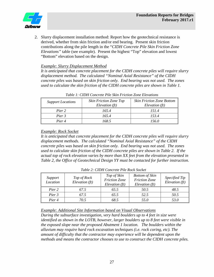
2. Slurry displacement installation method: Report how the geotechnical resistance is derived, whether from skin friction and/or end bearing. Present skin friction contributions along the pile length in the “CIDH Concrete Pile Skin Friction Zone Elevations” table (see example). Present the highest “Top” elevation and lowest “Bottom” elevation based on the design.
Example: Slurry Displacement Method It is anticipated that concrete placement for the CIDH concrete piles will require slurry displacement method. The calculated “Nominal Axial Resistance” of the CIDH concrete piles was based on skin friction only. End bearing was not used. The zones used to calculate the skin friction of the CIDH concrete piles are shown in Table 1.
Table 1: CIDH Concrete Pile Skin Friction Zone Elevations
0BSupport Locations Skin Friction Zone Top Elevation (ft)
Skin Friction Zone Bottom Elevation (ft)
Pier 2 165.4 151.4 Pier 3 165.4 153.4 Pier 4 168.5 156.0
Example: Rock Socket It is anticipated that concrete placement for the CIDH concrete piles will require slurry displacement methods. The calculated “Nominal Axial Resistance” of the CIDH concrete piles was based on skin friction only. End bearing was not used. The zones used to calculate skin friction of the CIDH concrete piles are shown in Table 2. If the actual top of rock elevation varies by more than XX feet from the elevation presented in Table 2, the Office of Geotechnical Design YY must be contacted for further instruction.
Table 2: CIDH Concrete Pile Rock Socket
Support Location
Top of Rock Elevation (ft)
Top of Skin Friction Zone Elevation (ft)
Bottom of Skin Friction Zone Elevation (ft)
Specified Tip Elevation (ft)
Pier 2 67.5 65.5 50.5 48.5 Pier 3 67.5 65.5 52.5 50.5 Pier 4 70.5 68.5 55.0 53.0
Example: Additional Site Information based on Visual Observations During the subsurface investigation, very hard boulders up to 4 feet in size were identified as shown in the LOTB, however, larger boulders up to 8 feet were visible in the exposed slope near the proposed Abutment 1 location. The boulders within the alluvium may require hard rock excavation techniques (i.e. rock coring, etc). The amount of difficulty that the contractor may experience will be dependent upon the methods and means the contractor chooses to use to construct the CIDH concrete piles.

Foundation Reports for Bridges February 2017.r1
28
3.12.3 Deep Foundations (Driven Piles) Present and/or discuss the following:
1. Information provided by Structure Designer a. Foundation Design Information Sheet (MTD 3-1, Attachment 1, Table 3-4) b. Foundation Factored Design Loads (MTD 3-1, Attachment 1, Table 3-5)
2. Information Provided by Geoprofessional a. Foundation Design Recommendations table (MTD 3-1, Attachment 1, Tables
3-6 & 3-7), with the following modifications: i. Modify the table to report the Nominal Resistance, not Required
Factored Nominal Resistance. ii. Add footnote: “Column heading modified from Required Factored
Nominal Resistance to Nominal Resistance.” iii. Report the resistance factors (in column header) using the appropriate
notations, e.g., φqs & φqp = 0.7 for side resistance & tip resistance (skin friction & end bearing), see AASHTO LRFD BDS, CA Amendment 10.3 & 10.5.5.2.3-1.
iv. The Nominal Resistance reported in the Foundation Design Recommendations table and the Pile Data Table must be rounded up to the nearest 10 kips.
b. For piles driven through zones not used for axial geotechnical resistance, (e.g., scourable layers, liquefiable layers), add the additional driving resistance to reach the specified tip elevation (STE) in the “Required Nominal Driving Resistance” column of the Foundation Design Recommendations table and the Pile Data Table (Table 3-6 & Table 3-7).
3. Pile acceptance criteria (e.g., per Standard Specification 49-2.01A(4)(c), dynamic monitoring, pile load test).
Notes to the Geoprofessional (Driven Piles) The following information is provided to assist the Geoprofessional in providing comprehensive and consistent recommendations. Some of this information will ultimately be moved to the Deep Foundation module of the Geotechnical Manual. 1. For driven piles with a nominal resistance greater than 600 kips, dynamic monitoring and
analyses are required (see Section 3.12.4 - Pile Load Testing and Dynamic Monitoring). 2. For driven piles with a diameter from 18 inches to 36 inches, dynamic monitoring and
analyses are required to verify that the pile will develop the nominal resistance (see Section 3.12.4 - Pile Load Testing and Dynamic Monitoring).
3. For driven piles that are larger than 36 inches, a Pile Load Test is required to verify that the pile will develop the nominal resistance (see Section 3.12.4 - Pile Load Testing and Dynamic Monitoring). Exceptions to the axial load test may include situations where geologic conditions (e.g., bearing in rock or very dense soil) provide confidence in the nominal resistance development. These cases must be reviewed by Foundation Testing & Instrumentation Branch and require approval of a design exception from the Office of

Foundation Reports for Bridges February 2017.r1
29
Geotechnical Design Policies and Practices (OGDPP) and Structures Policy and Innovation (SP&I).
Notes to the Structure Designer (Driven Piles) Provide the following (applicable) information in this section to aid in preparation of the contract plans. 1. If there are modifications to the Standard Plans, provide specifics so that the
modifications are shown on the project plans or Special Provisions.
Example All steel "H" piles are to have lugs installed prior to driving. It is recommended that the pile detail sheets or abutment detail sheets show the lugs as specified in the Bridge Construction Records and Procedures Manual, Bridge Construction Memo 130-5.0. Example Modified Class 200, Alternative "W" steel pipe pile details are to be shown on the project plans. The Modified Class 200, Alternative "W" steel pipe piles must be shown with a flat circular steel plate or conical steel tip with a minimum thickness of ¾ inch welded to the pile tip, similar to the Alternative "V" pile tip detail shown in the 2015 Standard Plans.
2. Provide a note to request that the Geoprofessional be notified if the lateral load tip
elevation is lower than the specified pile tip elevation, as a lower tip might be cause for revised design recommendations and/or construction considerations.
Example The Structure Designer must show on the plans, in the pile data table, the minimum pile design tip elevation required to meet the lateral load demands. If the specified pile tip elevation required to meet lateral load demands is lower than the specified pile tip elevation given within this report, the Office of Geotechnical Design XX, Branch X should be contacted for further evaluation.
Construction Considerations (Driven Piles) Provide the following (applicable) information in this section for use by the Specification Engineer, Structure Construction Representative, Contractor, and others. 1. State how the nominal resistance was developed.
Example The geotechnical resistance of the CISS piles was developed using external skin friction and end bearing based upon a combination of the end area of the steel shell and the internal skin friction of the portion of the soil plug that will be left in place.

Foundation Reports for Bridges February 2017.r1
30
2. State the allowable limits of center relief drilling for open-ended CISS piles.
Example At Abutment 4, it is anticipated that center relief drilling through the center of the CISS piles will be required to obtain the specified penetration. The center relief drilling must not extend beyond the pile tip during installation and must not extend below elevation 252 feet. Due to the presence of shallow groundwater at the site, any center relief drilling done to help advance the pile, must maintain a positive piezometric fluid head inside the CISS pile and the equipment or methods used for cleaning out steel shells must not cause quick soil conditions or cause scouring or caving of the hole below the pile tip.
3. State the top of soil plug elevation and the seal course thickness (if applicable) required
for the end bearing design of CISS piles.
Example At Abutment 4, a soil plug is utilized to develop internal skin friction in the lower portion of the CISS pile for end bearing design. The top of the soil plug elevation must be at elevation 252 feet. A seal course thickness of 5 feet is required to counteract the hydrostatic forces of the groundwater and to allow for the pile reinforcement and concrete to be poured in the dry. During the removal of the soil plug and during the placement of the seal course, the Contractor must maintain a positive piezometric fluid head inside the CISS pile.
4. Provide a cut-off and refusal criteria for pile acceptance.
Example Pile acceptance is to be based on Standard Specifications 49-2.01A(4)(c) "Department Acceptance." At Abutments 1 and 4 support locations, any pile that achieves 1½ times the nominal resistance in compression, as shown on the contract plans, within 5 feet of the specified pile tip elevation, may be accepted and cut off with written approval from the Engineer. (e.g. 1½ times the nominal resistance in compression is 580 kips at Abutment 1 and 600 kips at Abutment 4).
5. When predrilled holes are required beyond the requirements of the Standard
Specifications (49-2.01C(4)), for newly constructed fills or existing fills, state the elevation limits and locations of "Predrilled Holes" (Standard Specification 49-2.01C(4)).
Example At Abutment 1, predrilled holes through the existing fill to the elevations listed below in Table 1 are required prior to driving designated piles to minimize vibrations to nearby utilities. All predrilling must be done in accordance with Standard Specification Section 49-2.01C(4), "Predrilled Holes." Refer to the LOTB for details regarding the earth materials to be excavated.

Foundation Reports for Bridges February 2017.r1
31
Table 1: Abutment 1 - Bottom of Predrilled Hole Elevation
Support Location Bottom of Predrilled Hole Elevation (ft)
Abutment 1 173.0
6. State the allowable limits of "Drilling" to assist driven pile installation. (Standard
Specification 49-2.01C(3))
Example At Abutment 1, "Drilling" to assist pile driving through the alluvium soil and sedimentary rock down to the elevation listed in Table 1, below, will be required prior to driving each closed-ended pipe pile. All drilling to assist driving must be done in accordance with Standard Specification Section 49-2.01C(3), "Drilling." Refer to the LOTB for details regarding the earth materials to be excavated.
Table 1: Bottom of “Drilling” to Assist Driving Hole Elevation
Support Location Bottom of “Drilling” to Assist Driving Hole Elevation (ft)
Abutment 1 160.0
3.12.4 Pile Load Testing and Dynamic Monitoring
The Geoprofessional must consult with the Foundation Testing & Instrumentation (FTI) branch for all language and requirements in this section. The FTI branch will provide technical assistance in determining dynamic monitoring details, order of work, and layout of the load test piles. In addition, FTI can provide assistance with contractual details and information for the special provisions to be included in the FR. If the Geoprofessional is considering recommending a foundation type that would require a pile load test, the Geoprofessional must have a meeting with the FTI branch and the Structure Designer to review proposed pile load test loading schedule, layout, and to determine if any test or anchor piles may be incorporated in the proposed bridge foundation. Present and/or discuss the following for Pile Load Tests:
1. Control zones and associated support locations for the pile load tests. 2. Location, type and specified tip elevation of the load test pile and anchor piles in a pile
data table format. 3. Intent and type of the test(s) - Compressive and/or tensile resistance (ASTM D 1143,
ASTM D 3689) a. Proof test at Nominal Resistance b. Load to failure (defined by the Geoprofessional)
4. Dynamic monitoring requirements (typically the load test pile and at least one anchor pile).
Foundation Reports for Bridges February 2017.r1
32
5. Restrike schedule if pile-setup is anticipated. 6. Location and number of strain gauges per elevation, if applicable. 7. Test Pile Data Table and pile cut-off criteria as shown in the following example:
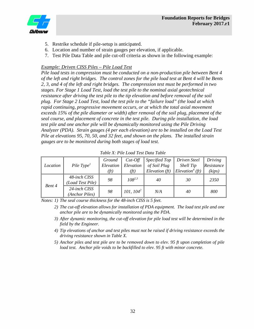
Example: Driven CISS Piles – Pile Load Test Pile load tests in compression must be conducted on a non-production pile between Bent 4 of the left and right bridges. The control zones for the pile load test at Bent 4 will be Bents 2, 3, and 4 of the left and right bridges. The compression test must be performed in two stages. For Stage 1 Load Test, load the test pile to the nominal axial geotechnical resistance after driving the test pile to the tip elevation and before removal of the soil plug. For Stage 2 Load Test, load the test pile to the “failure load” (the load at which rapid continuing, progressive movement occurs, or at which the total axial movement exceeds 15% of the pile diameter or width) after removal of the soil plug, placement of the seal course, and placement of concrete in the test pile. During pile installation, the load test pile and one anchor pile will be dynamically monitored using the Pile Driving Analyzer (PDA). Strain gauges (4 per each elevation) are to be installed on the Load Test Pile at elevations 95, 70, 50, and 32 feet, and shown on the plans. The installed strain gauges are to be monitored during both stages of load test.
Table X: Pile Load Test Data Table
Location Pile Type1 Ground
Elevation (ft)
Cut-Off Elevation
(ft)
Specified Top of Soil Plug
Elevation (ft)
Driven Steel Shell Tip
Elevation4 (ft)
Driving Resistance
(kips)
Bent 4
48-inch CISS (Load Test Pile) 98 1082,3 40 30 2350
24-inch CISS (Anchor Piles) 98 101, 1042 N/A 40 800
Notes: 1) The seal course thickness for the 48-inch CISS is 5 feet. 2) The cut-off elevation allows for installation of PDA equipment. The load test pile and one
anchor pile are to be dynamically monitored using the PDA. 3) After dynamic monitoring, the cut-off elevation for pile load test will be determined in the
field by the Engineer. 4) Tip elevations of anchor and test piles must not be raised if driving resistance exceeds the
driving resistance shown in Table X. 5) Anchor piles and test pile are to be removed down to elev. 95 ft upon completion of pile
load test. Anchor pile voids to be backfilled to elev. 95 ft with minor concrete.

Foundation Reports for Bridges February 2017.r1
33
Construction Considerations (Pile Load Testing and Dynamic Monitoring) Provide the following (applicable) information in this section for use by the Specification Engineer, Structure Construction Representative, Contractor, and others. When the contractor provides the required 10-day notification (per SS 49-1.01D(3)) prior to installing load test/anchor piles, the Structures Representative must contact the Foundation Testing and Instrumentation (FTI) branch and Geoprofessional. This is to allow coordination among Structures Representative, FTI and the Geoprofessional in order to schedule the pile load test, and to ensure that representatives from FTI are available to assist the contractor during construction of the load test equipment. Example: Driven Piles - Dynamic Monitoring At Piers 2, 4 and 6, dynamic monitoring with the Pile Driving Analyzer (PDA) is to be performed on the first CISS pile installed at those support locations and will determine pile acceptance criteria (SS 49-1.01D(4)). Each dynamically monitored pile will require an additional length equal to 2 times the diameter of the pile plus 2 feet for mounting of the PDA gauges. For dynamic monitoring locations and control zones, refer to Table X.
Table X: Dynamic Monitoring Pile Locations and Control Zones
Bridge No. Monitored Pile Locations Control Zone
57-1234 R/L Pier 2 Piers 2 & 3 Pier 4 Piers 4 & 5 Pier 6 Pier 6
3.12.5 Approach Fills
Approach fills, defined as the fill within 150 feet of the bridge abutment, must be constructed per Section 19 of the Standard Specifications. Present approach fill construction recommendations in this section. Reporting requirements for embankment construction on soft soil are presented in the Embankment module and the Ground Improvement module of the Geotechnical Manual. Note to the Geoprofessional (Approach Fills) In cases where settlement-related recommendations are presented, the Geoprofessional must collaborate with the author of the Geotechnical Design Report to assure that the recommendations are compatible. Issues to discuss may include:
• Anticipated settlement magnitude • Rate of construction and waiting periods • Prefabricated vertical drain spacing • Use of geosynthetics
Foundation Reports for Bridges February 2017.r1
34
3.13. Additional Considerations Provide any recommendations that have not already been addressed in any of the preceding sections.
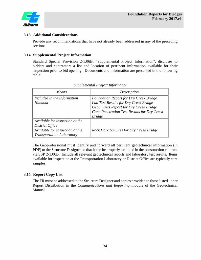
3.14. Supplemental Project Information Standard Special Provision 2-1.06B, "Supplemental Project Information", discloses to bidders and contractors a list and location of pertinent information available for their inspection prior to bid opening. Documents and information are presented in the following table:
Supplemental Project Information
Means Description Included in the Information Handout
Foundation Report for Dry Creek Bridge Lab Test Results for Dry Creek Bridge Geophysics Report for Dry Creek Bridge Cone Penetration Test Results for Dry Creek Bridge
Available for inspection at the District Office
Available for inspection at the Transportation Laboratory
Rock Core Samples for Dry Creek Bridge
The Geoprofessional must identify and forward all pertinent geotechnical information (in PDF) to the Structure Designer so that it can be properly included in the construction contract via SSP 2-1.06B. Include all relevant geotechnical reports and laboratory test results. Items available for inspection at the Transportation Laboratory or District Office are typically core samples.
3.15. Report Copy List The FR must be addressed to the Structure Designer and copies provided to those listed under Report Distribution in the Communications and Reporting module of the Geotechnical Manual.

Foundation Reports for Bridges February 2017.r1
35
3.16. Appendices
The Foundation Report appendices provide detailed information supporting foundation type selection, analyses, recommendations, and construction considerations. Reports prepared by Geotechnical Services staff must include:
Appendix I: Seismic Design Data Sheet Appendix II: Exceptions to Policy
Attach all approved "Request for Exception" forms. Reports prepared by consultants must include:
Appendix I: Site Map showing project location Appendix II: Log of Test Borings (including as-built LOTB) Appendix III: Field Exploration and Testing
Data acquired from field exploration and testing such as surface geologic mapping and surface geophysical surveys, logs from the Cone Penetration Test, Pressuremeter, Dilatometer, and in-situ Vane Shear Tests, Borehole Geophysical logging, indicator pile tests, Piezometer Readings, etc.
Appendix IV: Laboratory Test Results Soil and rock laboratory test results. Corrosion test results.
Appendix V: Seismic Design Data Sheet Appendix VI: Analyses and Calculations.
Engineering analyses and calculations supporting the foundation recommendations including all QC/QA signature sheets.
Appendix VII: Exceptions to Policy Attach all approved "Request for Exception" forms.