fpga based control method for three phase bldc motor
TRANSCRIPT
International Journal of Electrical and Computer Engineering (IJECE) Vol. 6, No. 4, August 2016, pp. 1434~1440 ISSN: 2088-8708, DOI: 10.11591/ijece.v6i4.10103 1434
Journal homepage: http://iaesjournal.com/online/index.php/IJECE
FPGA Based Control Method for Three Phase BLDC Motor
Suneeta1, R Srinivasan1, Ram Sagar2 1Departement of Electronics and Communication Engineering, Vemana Institute of Technology
2Founder Director, ARIES Nainital
Article Info ABSTRACT
Article history:
Received Jan 4, 2016 Revised Mar 12, 2016 Accepted Mar 26, 2016
This paper introduces a good method which is helpful to assist in the design and control of cost effective, efficient Brushless Direct Current (BLDC) motors. Speed Control of BLDC motor using PIC microcontrollers requires more hardware, and with the availability of FPGA versatile features motivated to develop a cost effective and reliable control with variable speed range. In this paper, an algorithm which uses the Resolver signals captured from the motor is developed with the help of Resolver to Digital converters. The program has been written using VHDL. This program generates the firing pulses required to drive the MOSFETs of three phase fully controlled bridge converter driven by drivers. Then the program has been loaded on the Spartan- 3 FPGA device and tested on the 30V, 2000 rpm BLDC motor which can make the motor run at constant speed ranging from 10 to 2000 rpm. The proposed hardware and the program are found to be very good and efficient. The results are good compare to PIC Microcontroller based design.
Keyword:
BLDC FPGA MOSFET RDC VHDL
Copyright © 2016 Institute of Advanced Engineering and Science. All rights reserved.
Corresponding Author:
Suneeta, Departement of Electronics and Communication Engineering, Vemana Institute of Technology, No 1 Mahayogi Vemana Road,Koramangala, Bangalore-560013,Karnataka, India. Email: [email protected]
1. INTRODUCTION
Permanent magnet brushless dc (BLDC) motors are used in wide application due to their power density and ease of control. Moreover, the machines have high efficiency over a wide speed range. The highly efficient conventional DC motors are suitable for various applications because of their characteristics [1]. They require commutators and brushes, for conversion of dc to ac which are subject to wear and require maintenance. This drawback of conventional DC motors makes to shift to BLDC motors which are electronically commutated. Recent efficiency standards in appliances, has forced appliance manufacturers to migrate to BLDC motors in their applications. In view of these enormous applications, researchers started developing methods for efficient use of these motors in diversified fields. To mention a few: Jianwen Shao Nolan et.al [2] has developed a novel microcontroller-based Sensor less brushless DC (BLDC) motor drive for automotive fuel pumps in 2003. Also, they have developed an Improved Microcontroller-Based Sensor less Brushless DC (BLDC) Motor Drive for Automotive Applications, in 2006 [3]. Nikolay Samoylenko [4] studied the Dynamic performance of Brushless DC motors with unbalanced Hall sensors. P. Devendra et.al [5] has developed a microcontroller-based control of three phase brushless DC (BLDC), in 2011.
To the extent the authors have surveyed not much work has been reported on FPGA driven Resolver based BLDC motors. Hence in this paper, an algorithm for resolver based FPGA driven BLDC motors are presented. Effectiveness of the work is specified through hardware realization.
IJECE ISSN: 2088-8708
FPGA Based Control Method for Three Phase BLDC Motor (Suneeta)
1435
2. REVIEW OF BLDC MOTOR CONTROL SCHEMES The control schemes of BLDC motor are mainly classified in following two ways
• Sensor based control • Sensor less control
In sensor based control, a Hall sensor is used which detects the position of the rotor magnet and gives a signal which is used to give appropriate excitation to the stator winding. Hall sensor works on Hall Effect which states that when a current carrying conductor is placed in magnetic field, it exerts a transverse force on the conductor.
The sensor less drive principle is based on the detection of the rotor position using various techniques one of which is the EMF detection. There are various methods for position and velocity estimation based on the induced Back EMF detection.
There are two main ways to monitor absolute shaft position those are encoders and resolvers. Resolvers are the older technology, but their ruggedness allows them to survive where other devices could not. Encoders, being inherently digital, have become the method of choice for most applications, but they can't survive where a resolver can.
A resolver is an electromechanical device with a mechanical design similar to a motor. It contains a rotor with one or two orthogonal primary windings and a stator with two orthogonal secondary windings. The voltage in one stator winding varies as the sine of the shaft angle and the other varies as the cosine. This resolver uses a rotary transformer to excite the primary, so no brushes are needed. An ac voltage is applied to the rotor and the voltage induced in each stator winding depends on the position of the shaft. Resolver-to-digital converters can be used to interpolate results.
These R/D converters give an absolute or incremental output with a resolution of up to 4096 counts per revolution. The resolver signals are low bandwidth amplitude modulated sine waves. The resolver to digital converter performs two basic functions: demodulation of the resolver format signals to remove the carrier, and angle determination to provide a digital representation of the rotor angle. The most popular method of performing these functions is called ratiometric tracking conversion.
Since the resolver secondary signals represent the sine and cosine of the rotor angle, the ratio of the signal amplitudes is the tangent of the rotor angle. Thus the rotor angle θ, is the arc tangent of the sine signal divided by the cosine signal. The ratiometric tracking converter performs an implicit arc tangent calculation on the ratio of the resolver signals by forcing a counter to track the position of the resolver. 3. FPGA BASED CONTROL SCHEME
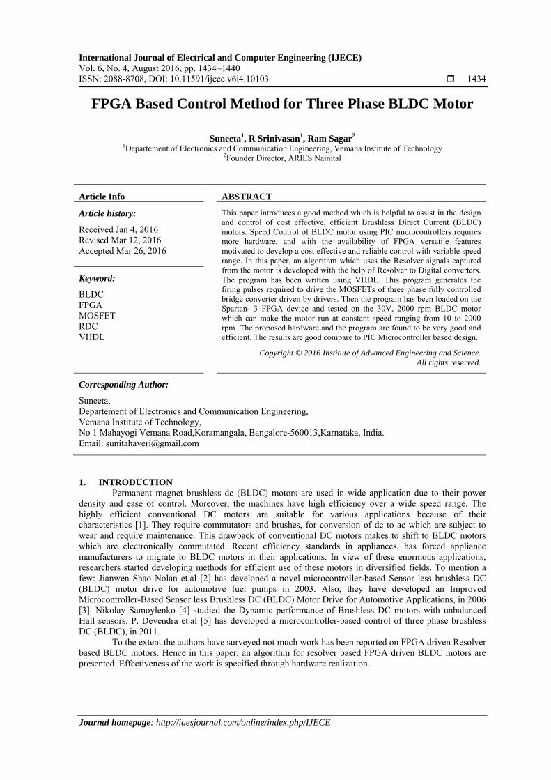
The proposed control scheme for BLDC motor control using VHDL coding on Spartan 3 FPGA device is shown in the Figure 1.
Figure 1. FPGA based Control
The drive to the MOSFETS in the inverter circuit is given by the Spartan 3 FPGA. The resolver signals from the motor are fed as inputs to the RDC. RDC provides position of the motor in digital form. Based on RDC position and the direction of rotation of the motor, the corresponding gate drive is made active by the FPGA and fed to the stator of the BLDC motor. The commutation sequence for rotating the motor in clock wise direction when viewed from the non driving end is given in the Table 1.
ISSN: 2088-8708
IJECE Vol. 6, No. 4, August 2016 : 1434 – 1440
1436
Table 1. The Six States and Coil Current Directions State A B C
State 1 Positive Nil Negative State 2 Positive Negative Nil State 3 Nil Negative Positive State 4 Negative Nil Positive State 5 Negative Positive Nil State 6 Nil Positive Negative
Based on the RDC input to the FPGA, the corresponding MOSFETs are made active and current flows through two windings and the other winding is inactive and hence commutation is done electronically with the use of a FPGA.
Exciting the corresponding winding based on the RDC signal, the motor is commutated and is made to run at the desired speed. Initially irrespective of the rotor position, the windings are excited in the given sequence and once the motor starts rotating, rotor position is sensed by the resolver and then the motor is excited based on the RDC signal and according to the direction of rotation of the motor.
The speed can be controlled in a closed loop by measuring the actual speed of the motor. If the speed is greater than the desired rated speed, then all the MOSFETs are turned off for a short duration and then again excited based on the RDC position and accordingly speed can be adjusted to get constant speed. The ADC0800 is used to convert the analog signal corresponding to the speed of the motor to a digital value and comparison is done with the calculated digital value which is proportional to the rated speed. 3.1. Spartan 3 FPGA
The Spartan-3 family of Field-Programmable Gate Arrays is specifically designed to meet the needs of high volume, cost-sensitive consumer electronic applications. It offers densities ranging from 50,000 to 5,000,000 system gates.
The Spartan-3 FPGA enhancements, combined with advanced process technology, deliver more functionality and bandwidth. Because of their exceptionally low cost, Spartan-3 FPGAs are ideally suited to a wide range of consumer electronics applications.
The Spartan-3 family is a superior alternative to mask programmed ASICs. FPGAs avoid the high initial cost, the lengthy development cycles, and the inherent inflexibility of conventional ASICs. Also, FPGA programmability permits design upgrades in the field with no hardware replacement necessary, an impossibility with ASICs. The Spartan-3 family architecture consists of five fundamental programmable functional elements those are Configurable Logic Blocks (CLBs) contain RAM-based Look-Up Tables (LUTs) to implement logic and
storage elements that can be used as flip-flops or latches. CLBs can be programmed to perform a wide variety of logical functions as well as to store data.
Input/output Blocks (IOBs) control the flow of data between the I/O pins and the internal logic of the device. Each IOB supports bidirectional data flow plus 3-state operation. Twenty-six different signal standards, including eight high-performance differential standards. Double Data-Rate (DDR) registers are included. The Digitally Controlled Impedance (DCI) feature provides automatic on-chip terminations, simplifying board designs.
Block RAM provides data storage in the form of 18-Kbit dual-port blocks. Multiplier blocks accept two 18-bit binary numbers as inputs and calculate the product. Digital Clock Manager (DCM) blocks provide self-calibrating, fully digital solutions for distributing,
delaying, multiplying, dividing, and phase shifting clock signals. This algorithm is used to write a program in VHDL and is loaded on to the FPGA Spartan 3 device
and tested on the 30 V and 2000 rpm BLDC motor shown in the Figure 2. Motor is capable to operate with 160v and 7000rpm speed.

IJECE ISSN: 2088-8708
FPGA Based Control Method for Three Phase BLDC Motor (Suneeta)
1437
Figure 2. 30 V, 2000 rpm BLDC motor
4. PROPOSED HARDWARE FOR BLDC MOTOR
Proposed hardware schematic structure is shown in Figure 3. The VHDL program has been written and tested on simulator and hardware.
4.1. RTL Schematic
Figure 3. RTL Schematic of FPGA control circuit
4.2. MOSFET Driver Circuit The basic hardware structure to run an BLDC motor is inverter bridge. The signal generated from
FPGA is fed into inverter through opto- isolators. The inverter circuit is shown in Figure 4.
ISSN: 2088-8708
IJECE Vol. 6, No. 4, August 2016 : 1434 – 1440
1438
Figure 4. MOSFET driver circuit
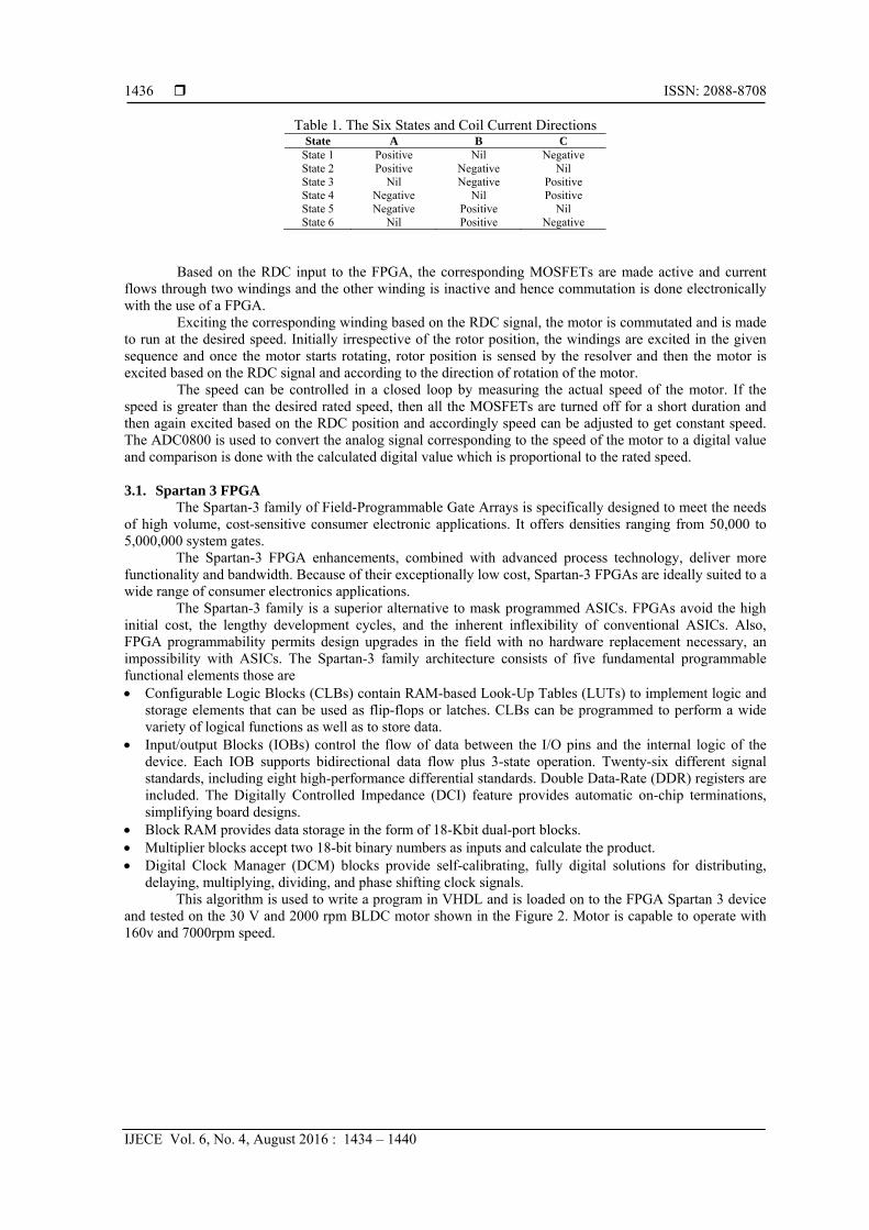
The complete hardware set up for the motor control is shown in Figure 5.
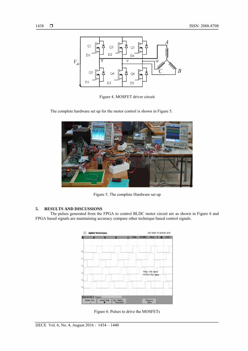
Figure 5. The complete Hardware set up 5. RESULTS AND DISCUSSIONS
The pulses generated from the FPGA to control BLDC motor circuit are as shown in Figure 6 and FPGA based signals are maintaining accuracy compare other technique based control signals.
Figure 6. Pulses to drive the MOSFETs
IJECE ISSN: 2088-8708
FPGA Based Control Method for Three Phase BLDC Motor (Suneeta)
1439
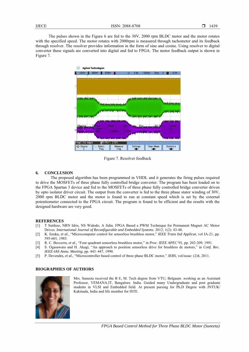
The pulses shown in the Figure 6 are fed to the 30V, 2000 rpm BLDC motor and the motor rotates with the specified speed. The motor rotates with 2000rpm is measured through tachometer and its feedback through resolver. The resolver provides information in the form of sine and cosine. Using resolver to digital converter these signals are converted into digital and fed to FPGA. The motor feedback output is shown in Figure 7.
Figure 7. Resolver feedback 6. CONCLUSION
The proposed algorithm has been programmed in VHDL and it generates the firing pulses required to drive the MOSFETs of three phase fully controlled bridge converter. The program has been loaded on to the FPGA Spartan 3 device and fed to the MOSFETs of three phase fully controlled bridge converter driven by opto isolator driver circuit. The output from the converter is fed to the three phase stator winding of 30V, 2000 rpm BLDC motor and the motor is found to run at constant speed which is set by the external potentiometer connected to the FPGA circuit. The program is found to be efficient and the results with the designed hardware are very good. REFERENCES [1] T Sutikno, NRN Idris, NS Widodo, A Jidin. FPGA Based a PWM Technique for Permanent Magnet AC Motor
Drives. International Journal of Reconfigurable and Embedded Systems. 2012; 1(2): 43-48. [2] K. Iizuka, et al., “Microcomputer control for sensorless brushless motor,” IEEE Trans Ind Applicat, vol IA-21, pp.
595-601, 1985. [3] R. C. Beccerra, et al., “Four quadrant sensorless brushless motor,” in Proc. IEEE APEC’91, pp. 202-209, 1991. [4] S. Ogasawara and H. Akagi, “An approach to position sensorless drive for brushless dc motors,” in Conf. Rec.
IEEE-IAS Annu. Meeting, pp. 443–447, 1990. [5] P. Devendra, et al., “Microcontroller based control of three phase BLDC motor,” JERS, vol/issue: (2)4, 2011. BIOGRAPHIES OF AUTHORS
Mrs. Suneeta received the B E, M. Tech degree from VTU; Belgaum .working as an Assistant Professor, VEMANA.IT, Bangalore. India. Guided many Undergraduate and post graduate students in VLSI and Embedded field. At present pursing for Ph.D Degree with JNTUK/ Kakinada, India and life member for ISTE.

ISSN: 2088-8708
IJECE Vol. 6, No. 4, August 2016 : 1434 – 1440
1440
Dr. R. Srinivasan obtained his Bachlors, master’s and doctorate degree from IISc, Bangalore, India. He has served as Scientist with National Aerospace Laboratories Bangalore and with Indian Institute of Astrophysics, Bangalore in various capacities and specialized in analog/digital Controls and servo systems related to astronomical instrumentation. He has number of papers to his credit with national & international Journals/conferences.
Prof. Ram Sagar completed his M.Sc. (1973) and Ph.D. (1981) in Physics from University of Gorakhpur. He joined the U.P State Observatory, Nainital in 1979, where he was the director during 1996 - 2000. Prof. Ram Sagar spent some time at the Kumaon University, Nainital, as faculty member in Physics Department during 1979-1986. He then joined and worked at the Indian Institute of Astrophysics, Bangalore until 2000, when he moved to Nainital, as the Director of the State Observatory there (2000-2004). He subsequently moved to the Aryabhatta Research Institute of Observational Sciences (ARIES) in 2004 as its director. His areas of research interest are Star - formation and stellar evolution, Star clusters, GRBs, AGNs, Aster seismology, Gravitational lensing and Atmospheric Physics. He is a Chief Editor of Journal of Astrophysics and Astronomy since 2013.Prof. Ram Sagar is a fellow of the Indian Academy of Sciences, Bangalore, India, National Academy of Sciences, Allahabad, India and Laser and Spectroscopic Society of India. He is a recipient of the Astronomical Society of India Young Astronomer’s award (1983–84), the Royal Society, London, Commonwealth Bursary fellowship (1983–85), the Alexander von Humboldt Foundation German Research fellowship (1990), and Rajiv Gandhi Sadbhavana Award as Eminent Scientist of the year 2009. He has published over 225 research papers in refereed journals and another over 120 contributions in proceedings etc. His scientific work has been cited over 4000 times in the reputed peer reviewed journals.