fr-a800-e ethernet function manual - sirius...
TRANSCRIPT
Ethernet communication function
800
ETHERNET FUNCTION MANUAL
This manual explains the Ethernet communication specifications. For the functions not found in this manual, referto the Instruction Manual (Detailed) of the FR-A800 inverter.In addition to this manual, please read the Instruction Manual (Detailed) of the FR-A800 inverter carefully. Do notuse this product until you have a full knowledge of the equipment, safety information and instructions.Please forward this manual to the end user.
INVERTER
A800-E
2 CONTENTS
1 INTRODUCTION 31.1 Ethernet communication overview 3
1.2 Ethernet connector 4
1.3 Ethernet cable wiring precautions 5
1.4 Removal of the Ethernet board 6
2 PARAMETER 72.1 Parameter list (by parameter number) 7
2.2 Parameter list (by function group) 8
2.3 (D) Operation command and frequency command 9
2.3.1 Selection of the command source during communication operation................................................................ 9
2.4 (N) Operation via communication and its settings 13
2.4.1 Initial setting of operation via communication................................................................................................. 132.4.2 Initial settings and specifications of Ethernet communication ........................................................................ 182.4.3 MELSOFT / FA product connection ............................................................................................................... 252.4.4 SLMP.............................................................................................................................................................. 262.4.5 Modbus/TCP .................................................................................................................................................. 38
3 PROTECTIVE FUNCTIONS 503.1 Causes and corrective actions 50
4 SPECIFICATIONS 514.1 Common specifications 51
4.2 Parameters (functions) and instruction codes under different control methods 53
CONTENTS
Ethernet communication overview
INTRODUCTION 3
1
1 INTRODUCTION
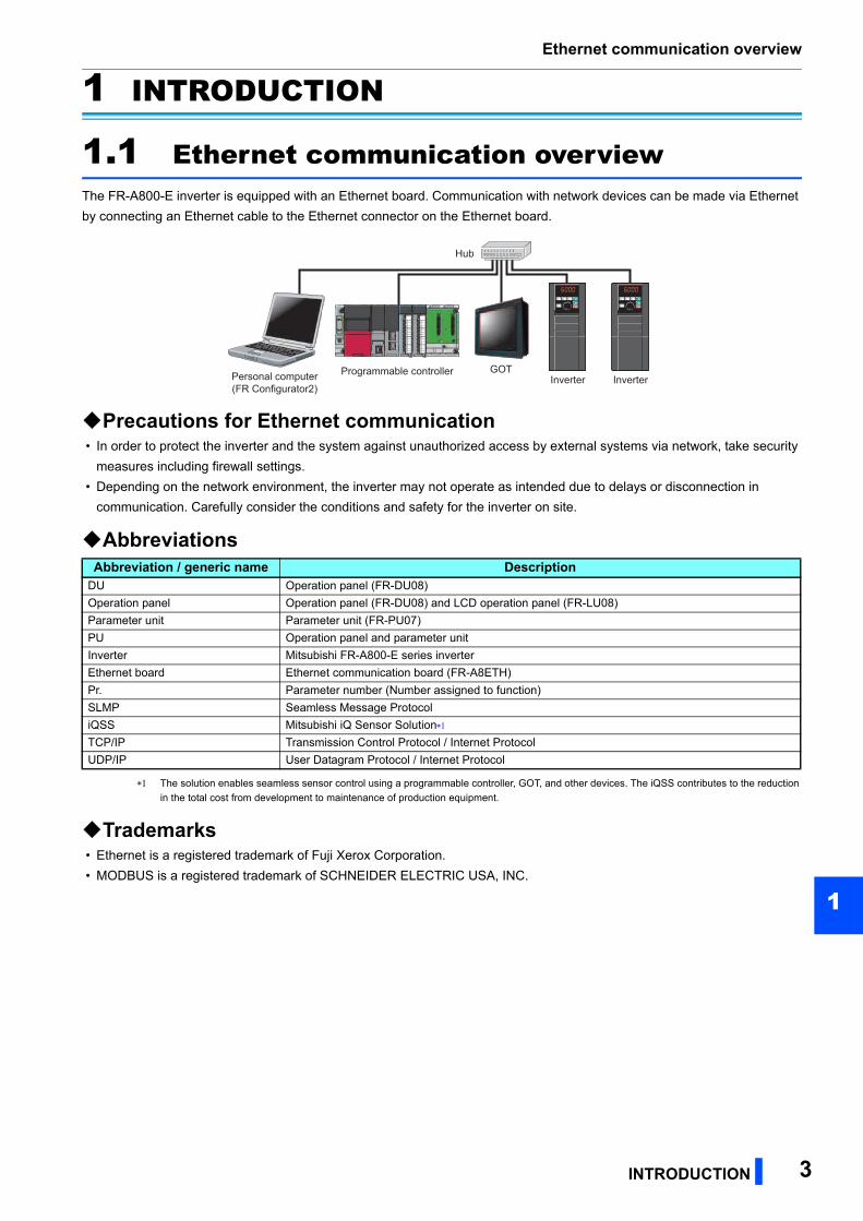
1.1 Ethernet communication overviewThe FR-A800-E inverter is equipped with an Ethernet board. Communication with network devices can be made via Ethernet
by connecting an Ethernet cable to the Ethernet connector on the Ethernet board.
Precautions for Ethernet communication • In order to protect the inverter and the system against unauthorized access by external systems via network, take security
measures including firewall settings.
• Depending on the network environment, the inverter may not operate as intended due to delays or disconnection in
communication. Carefully consider the conditions and safety for the inverter on site.
Abbreviations
The solution enables seamless sensor control using a programmable controller, GOT, and other devices. The iQSS contributes to the reduction
in the total cost from development to maintenance of production equipment.
Trademarks • Ethernet is a registered trademark of Fuji Xerox Corporation.
• MODBUS is a registered trademark of SCHNEIDER ELECTRIC USA, INC.
Abbreviation / generic name DescriptionDU Operation panel (FR-DU08)
Operation panel Operation panel (FR-DU08) and LCD operation panel (FR-LU08)
Parameter unit Parameter unit (FR-PU07)
PU Operation panel and parameter unit
Inverter Mitsubishi FR-A800-E series inverter
Ethernet board Ethernet communication board (FR-A8ETH)
Pr. Parameter number (Number assigned to function)
SLMP Seamless Message Protocol
iQSS Mitsubishi iQ Sensor Solution
TCP/IP Transmission Control Protocol / Internet Protocol
UDP/IP User Datagram Protocol / Internet Protocol
Hub
Inverter InverterPersonal computer(FR Configurator2)
Programmable controller GOT
Ethernet connector
4 INTRODUCTION
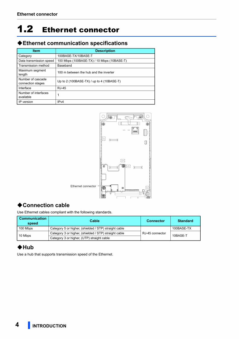
1.2 Ethernet connector
Ethernet communication specifications
Connection cableUse Ethernet cables compliant with the following standards.
HubUse a hub that supports transmission speed of the Ethernet.
Item DescriptionCategory 100BASE-TX/10BASE-T
Data transmission speed 100 Mbps (100BASE-TX) / 10 Mbps (10BASE-T)
Transmission method Baseband
Maximum segment length
100 m between the hub and the inverter
Number of cascade connection stages
Up to 2 (100BASE-TX) / up to 4 (10BASE-T)
Interface RJ-45
Number of interfaces available
1
IP version IPv4
Communication speed
Cable Connector Standard
100 Mbps Category 5 or higher, (shielded / STP) straight cable
RJ-45 connector
100BASE-TX
10 MbpsCategory 3 or higher, (shielded / STP) straight cable
10BASE-TCategory 3 or higher, (UTP) straight cable
Ethernet connector
Ethernet cable wiring precautions
INTRODUCTION 5
1
1.3 Ethernet cable wiring precautionsThis section explains Ethernet cable connection and the relevant precautions.
Handling of the Ethernet cable • Do not touch the conductors of the cable or the connector on the inverter. Keep the conductors free of dust or dirt. Handling
the conductors with oily hands or dust/dirt adhesion to the conductors may cause transmission losses and impair normal
data link operation.
• Check the Ethernet cable for the following points before use.
• The cable is not broken.
• The cable does not have a short circuit.
• The connector is properly installed.
• Do not use an Ethernet cable with a broken latch. Doing so may cause the cable to come off or malfunction.
• Do not connect the Ethernet cable to the PU connector. The product could be damaged due to differences in electrical
specifications.
• The maximum distance between stations is specified as 100 m. However, the maximum distance may be shorter
depending on the environment. For details of the cable, contact your cable manufacturer.
Connecting and disconnecting of the Ethernet cableHold the cable connector when connecting and disconnecting the Ethernet cable. Pulling a cable connected to the inverter
may damage the inverter or cable, or result in malfunction due to poor contact.
Network configurationCheck the network configuration before wiring, and perform correct wiring.

Removal of the Ethernet board
6 INTRODUCTION
1.4 Removal of the Ethernet boardThe option connector 2 is not available for use because the Ethernet board is installed in the initial status. The Ethernet board
must be removed as follows to install a plug-in option to the option connector 2.
(However, Ethernet communication is disabled in that case.)
(1) Remove the inverter front cover. (For details on how to remove the front cover, refer to Chapter 2 of the inverter's
Instruction Manual (Detailed).)
(2) Remove the three mounting screws to remove the Ethernet board earth plate and the Ethernet board.
NOTE • For reinstalling the Ethernet board to the inverter, remove the plug-in option installed to the option connector 2 and install the
Ethernet board and its earth plate in the reverse order.
• Remove the Ethernet board for the SSCNET III(/H) communication operation with the FR-A8NS and FR-A8AP/FR-A8AL.
Ethernet board earth plate
Parameter list (by parameter number)
PARAMETER 7
2
2 PARAMETER
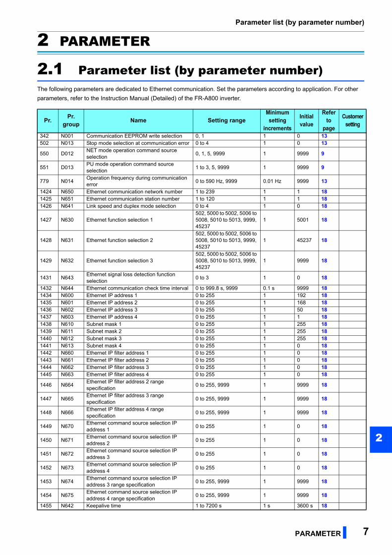
2.1 Parameter list (by parameter number)The following parameters are dedicated to Ethernet communication. Set the parameters according to application. For other
parameters, refer to the Instruction Manual (Detailed) of the FR-A800 inverter.
Pr.Pr.
groupName Setting range
Minimum setting
increments
Initial value
Refer to
page
Customersetting
342 N001 Communication EEPROM write selection 0, 1 1 0 13502 N013 Stop mode selection at communication error 0 to 4 1 0 13
550 D012NET mode operation command source selection
0, 1, 5, 9999 1 9999 9
551 D013PU mode operation command source selection
1 to 3, 5, 9999 1 9999 9
779 N014Operation frequency during communication error
0 to 590 Hz, 9999 0.01 Hz 9999 13
1424 N650 Ethernet communication network number 1 to 239 1 1 181425 N651 Ethernet communication station number 1 to 120 1 1 181426 N641 Link speed and duplex mode selection 0 to 4 1 0 18
1427 N630 Ethernet function selection 1502, 5000 to 5002, 5006 to 5008, 5010 to 5013, 9999, 45237
1 5001 18
1428 N631 Ethernet function selection 2502, 5000 to 5002, 5006 to 5008, 5010 to 5013, 9999, 45237
1 45237 18
1429 N632 Ethernet function selection 3502, 5000 to 5002, 5006 to 5008, 5010 to 5013, 9999, 45237
1 9999 18
1431 N643Ethernet signal loss detection function selection
0 to 3 1 0 18
1432 N644 Ethernet communication check time interval 0 to 999.8 s, 9999 0.1 s 9999 181434 N600 Ethernet IP address 1 0 to 255 1 192 181435 N601 Ethernet IP address 2 0 to 255 1 168 181436 N602 Ethernet IP address 3 0 to 255 1 50 181437 N603 Ethernet IP address 4 0 to 255 1 1 181438 N610 Subnet mask 1 0 to 255 1 255 181439 N611 Subnet mask 2 0 to 255 1 255 181440 N612 Subnet mask 3 0 to 255 1 255 181441 N613 Subnet mask 4 0 to 255 1 0 181442 N660 Ethernet IP filter address 1 0 to 255 1 0 181443 N661 Ethernet IP filter address 2 0 to 255 1 0 181444 N662 Ethernet IP filter address 3 0 to 255 1 0 181445 N663 Ethernet IP filter address 4 0 to 255 1 0 18
1446 N664Ethernet IP filter address 2 range specification
0 to 255, 9999 1 9999 18
1447 N665Ethernet IP filter address 3 range specification
0 to 255, 9999 1 9999 18
1448 N666Ethernet IP filter address 4 range specification
0 to 255, 9999 1 9999 18
1449 N670Ethernet command source selection IP address 1
0 to 255 1 0 18
1450 N671Ethernet command source selection IP address 2
0 to 255 1 0 18
1451 N672Ethernet command source selection IP address 3
0 to 255 1 0 18
1452 N673Ethernet command source selection IP address 4
0 to 255 1 0 18
1453 N674Ethernet command source selection IP address 3 range specification
0 to 255, 9999 1 9999 18
1454 N675Ethernet command source selection IP address 4 range specification
0 to 255, 9999 1 9999 18
1455 N642 Keepalive time 1 to 7200 s 1 s 3600 s 18
Parameter list (by function group)
8 PARAMETER
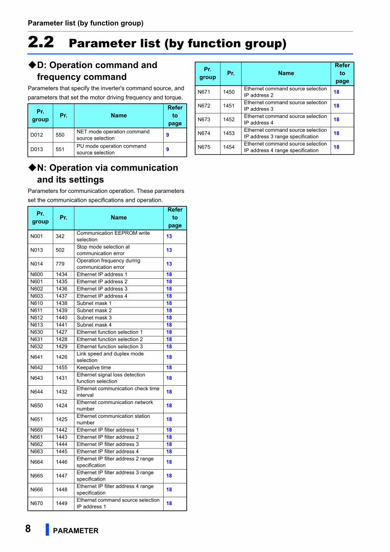
2.2 Parameter list (by function group)
D: Operation command and frequency command
Parameters that specify the inverter's command source, and
parameters that set the motor driving frequency and torque.
N: Operation via communication and its settings
Parameters for communication operation. These parameters
set the communication specifications and operation.
Pr.group
Pr. NameRefer
topage
D012 550NET mode operation command source selection
9
D013 551PU mode operation command source selection
9
Pr.group
Pr. NameRefer
topage
N001 342Communication EEPROM write selection
13
N013 502Stop mode selection at communication error
13
N014 779Operation frequency during communication error
13
N600 1434 Ethernet IP address 1 18N601 1435 Ethernet IP address 2 18N602 1436 Ethernet IP address 3 18N603 1437 Ethernet IP address 4 18N610 1438 Subnet mask 1 18N611 1439 Subnet mask 2 18N612 1440 Subnet mask 3 18N613 1441 Subnet mask 4 18N630 1427 Ethernet function selection 1 18N631 1428 Ethernet function selection 2 18N632 1429 Ethernet function selection 3 18
N641 1426Link speed and duplex mode selection
18
N642 1455 Keepalive time 18
N643 1431Ethernet signal loss detection function selection
18
N644 1432Ethernet communication check time interval
18
N650 1424Ethernet communication network number
18
N651 1425Ethernet communication station number
18
N660 1442 Ethernet IP filter address 1 18N661 1443 Ethernet IP filter address 2 18N662 1444 Ethernet IP filter address 3 18N663 1445 Ethernet IP filter address 4 18
N664 1446Ethernet IP filter address 2 range specification
18
N665 1447Ethernet IP filter address 3 range specification
18
N666 1448Ethernet IP filter address 4 range specification
18
N670 1449Ethernet command source selection IP address 1
18
N671 1450Ethernet command source selection IP address 2
18
N672 1451Ethernet command source selection IP address 3
18
N673 1452Ethernet command source selection IP address 4
18
N674 1453Ethernet command source selection IP address 3 range specification
18
N675 1454Ethernet command source selection IP address 4 range specification
18
Pr.group
Pr. NameRefer
topage
(D) Operation command and frequency command
PARAMETER 9
2
GROUP
D
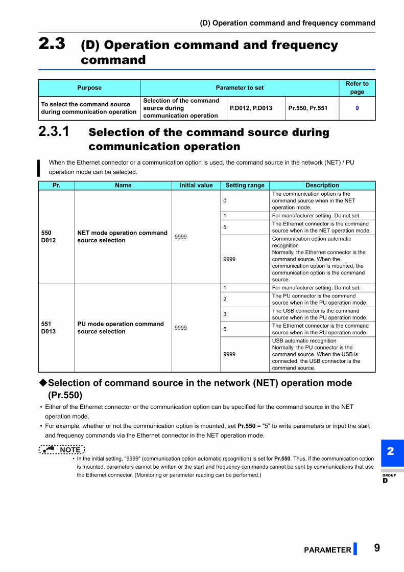
2.3 (D) Operation command and frequency command
2.3.1 Selection of the command source during communication operation
Selection of command source in the network (NET) operation mode (Pr.550)
• Either of the Ethernet connector or the communication option can be specified for the command source in the NET
operation mode.
• For example, whether or not the communication option is mounted, set Pr.550 = "5" to write parameters or input the start
and frequency commands via the Ethernet connector in the NET operation mode.
NOTE • In the initial setting, "9999" (communication option automatic recognition) is set for Pr.550. Thus, if the communication option
is mounted, parameters cannot be written or the start and frequency commands cannot be sent by communications that use
the Ethernet connector. (Monitoring or parameter reading can be performed.)
Purpose Parameter to setRefer to
page
To select the command source during communication operation
Selection of the command source during communication operation
P.D012, P.D013 Pr.550, Pr.551 9
When the Ethernet connector or a communication option is used, the command source in the network (NET) / PU
operation mode can be selected.
Pr. Name Initial value Setting range Description
550D012
NET mode operation command source selection
9999
0The communication option is the command source when in the NET operation mode.
1 For manufacturer setting. Do not set.
5The Ethernet connector is the command source when in the NET operation mode.
9999
Communication option automatic recognitionNormally, the Ethernet connector is the command source. When the communication option is mounted, the communication option is the command source.
551D013
PU mode operation command source selection
9999
1 For manufacturer setting. Do not set.
2The PU connector is the command source when in the PU operation mode.
3The USB connector is the command source when in the PU operation mode.
5The Ethernet connector is the command source when in the PU operation mode.
9999
USB automatic recognitionNormally, the PU connector is the command source. When the USB is connected, the USB connector is the command source.
(D) Operation command and frequency command
10 PARAMETER
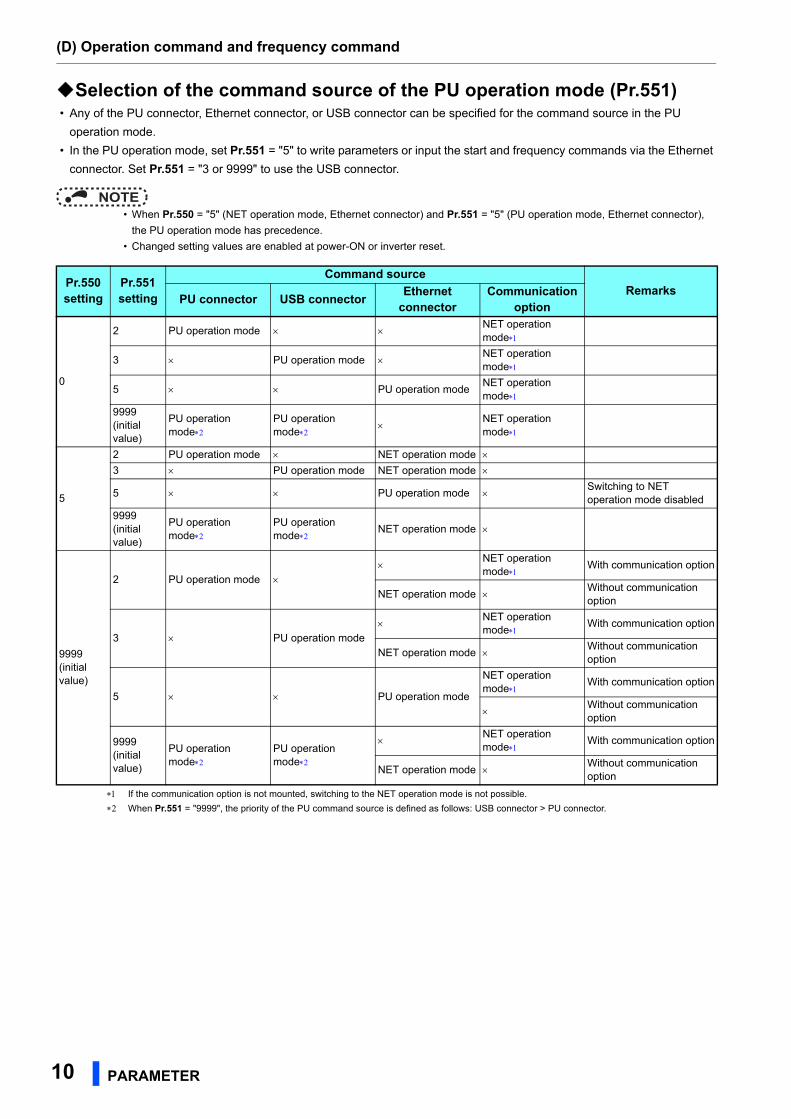
Selection of the command source of the PU operation mode (Pr.551) • Any of the PU connector, Ethernet connector, or USB connector can be specified for the command source in the PU
operation mode.
• In the PU operation mode, set Pr.551 = "5" to write parameters or input the start and frequency commands via the Ethernet
connector. Set Pr.551 = "3 or 9999" to use the USB connector.
NOTE • When Pr.550 = "5" (NET operation mode, Ethernet connector) and Pr.551 = "5" (PU operation mode, Ethernet connector),
the PU operation mode has precedence.
• Changed setting values are enabled at power-ON or inverter reset.
If the communication option is not mounted, switching to the NET operation mode is not possible.
When Pr.551 = "9999", the priority of the PU command source is defined as follows: USB connector > PU connector.
Pr.550setting
Pr.551setting
Command sourceRemarks
PU connector USB connectorEthernet
connectorCommunication
option
0
2 PU operation mode NET operation mode
3 PU operation mode NET operation mode
5 PU operation modeNET operation mode
9999(initial value)
PU operation mode
PU operation mode
NET operation mode
5
2 PU operation mode NET operation mode 3 PU operation mode NET operation mode
5 PU operation mode Switching to NET operation mode disabled
9999(initial value)
PU operation mode
PU operation mode
NET operation mode
9999(initial value)
2 PU operation mode
NET operation mode
With communication option
NET operation mode Without communication option
3 PU operation mode
NET operation mode
With communication option
NET operation mode Without communication option
5 PU operation mode
NET operation mode
With communication option
Without communication option
9999(initial value)
PU operation mode
PU operation mode
NET operation mode
With communication option
NET operation mode Without communication option
(D) Operation command and frequency command
PARAMETER 11
2
GROUP
D
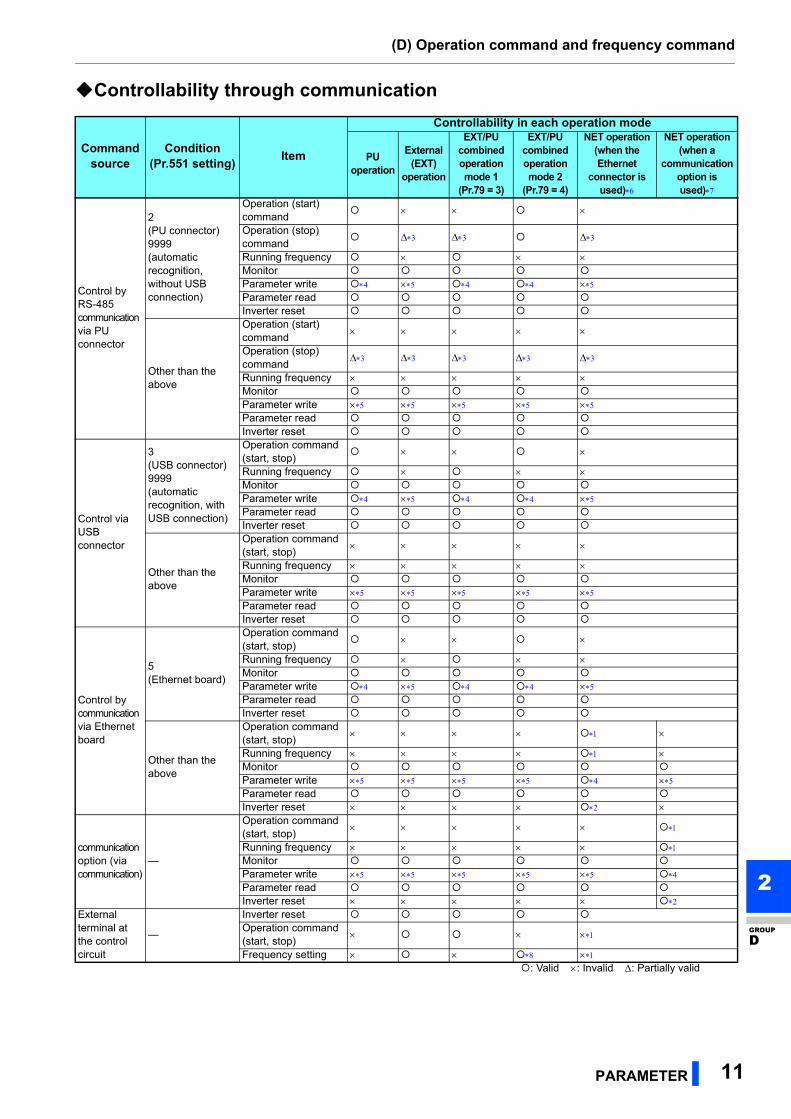
Controllability through communication
Command source
Condition(Pr.551 setting)
Item
Controllability in each operation mode
PUoperation
External (EXT)
operation
EXT/PU combined operation mode 1
(Pr.79 = 3)
EXT/PU combined operation mode 2
(Pr.79 = 4)
NET operation(when the Ethernet
connector is used)
NET operation(when a
communication option is used)
Control by RS-485 communication via PU connector
2(PU connector)9999(automatic recognition, without USB connection)
Operation (start) command
Operation (stop) command
Running frequency Monitor Parameter write Parameter read Inverter reset
Other than the above
Operation (start) command
Operation (stop) command
Running frequency Monitor Parameter write Parameter read Inverter reset
Control via USB connector
3(USB connector)9999(automatic recognition, with USB connection)
Operation command (start, stop)
Running frequency Monitor Parameter write Parameter read Inverter reset
Other than the above
Operation command (start, stop)
Running frequency Monitor Parameter write Parameter read Inverter reset
Control by communication via Ethernet board
5(Ethernet board)
Operation command (start, stop)
Running frequency Monitor Parameter write Parameter read Inverter reset
Other than the above
Operation command (start, stop)
Running frequency Monitor Parameter write Parameter read Inverter reset
communication option (via communication)
—
Operation command (start, stop)
Running frequency
Monitor Parameter write
Parameter read Inverter reset
External terminal at the control circuit
—
Inverter reset Operation command (start, stop)
Frequency setting : Valid : Invalid : Partially valid
(D) Operation command and frequency command
12 PARAMETER
The operation is as set in Pr.338 Communication operation command source and Pr.339 Communication speed command source. (Refer
to the Instruction Manual (Detailed) of the FR-A800 inverter.)
At occurrence of communication error, the inverter cannot be reset.
Enabled only when stopped by the PU. "PS" is displayed on the operation panel for the PU stop. The operation is as set in Pr.75 Reset
selection/disconnected PU detection/PU stop selection. (Refer to the Instruction Manual (Detailed) of the FR-A800 inverter.)
Writing of some parameters may be disabled by the Pr.77 Parameter write selection setting and the operating condition. (Refer to the
Instruction Manual (Detailed) of the FR-A800 inverter.)
Some parameters are write-enabled independently of the operation mode and command source presence/absence. Writing is also enabled
when Pr.77 = "2". (Refer to the Instruction Manual (Detailed) of the FR-A800 inverter.) Parameter clear is disabled.
Applicable when Pr.550 NET mode operation command source selection = "5" (Ethernet connector enabled), or Pr.550 NET mode
operation command source selection = "9999" with no communication option connected
Applicable when Pr.550 NET mode operation command source selection = "0 (communication option enabled)", or Pr.550 NET mode
operation command source selection = "9999" with communication option connected
The frequency can be set by multi-speed setting or input through terminal 4.
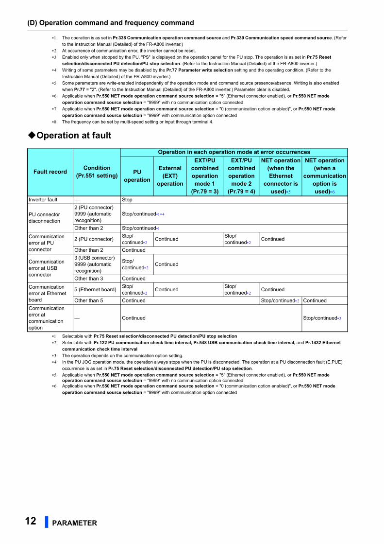
Operation at fault
Selectable with Pr.75 Reset selection/disconnected PU detection/PU stop selection
Selectable with Pr.122 PU communication check time interval, Pr.548 USB communication check time interval, and Pr.1432 Ethernet
communication check time interval
The operation depends on the communication option setting.
In the PU JOG operation mode, the operation always stops when the PU is disconnected. The operation at a PU disconnection fault (E.PUE)
occurrence is as set in Pr.75 Reset selection/disconnected PU detection/PU stop selection.
Applicable when Pr.550 NET mode operation command source selection = "5" (Ethernet connector enabled), or Pr.550 NET mode operation command source selection = "9999" with no communication option connected
Applicable when Pr.550 NET mode operation command source selection = "0 (communication option enabled)", or Pr.550 NET mode
operation command source selection = "9999" with communication option connected
Fault recordCondition
(Pr.551 setting)
Operation in each operation mode at error occurrences
PU operation
External (EXT)
operation
EXT/PU combined operation mode 1
(Pr.79 = 3)
EXT/PU combined operation mode 2
(Pr.79 = 4)
NET operation(when the Ethernet
connector is used)
NET operation(when a
communication option is used)
Inverter fault — Stop
PU connector disconnection
2 (PU connector)9999 (automatic recognition)
Stop/continued
Other than 2 Stop/continued
Communication error at PU connector
2 (PU connector)Stop/continued
ContinuedStop/continued
Continued
Other than 2 Continued
Communication error at USB connector
3 (USB connector)9999 (automatic recognition)
Stop/continued
Continued
Other than 3 Continued
Communication error at Ethernet board
5 (Ethernet board)Stop/continued
ContinuedStop/continued
Continued
Other than 5 Continued Stop/continued Continued
Communication error at communication option
— Continued Stop/continued
(N) Operation via communication and its settings
PARAMETER 13
2
GROUP
N
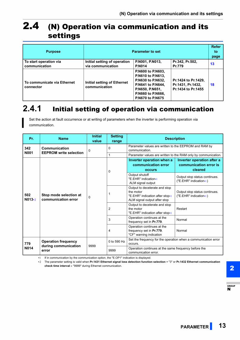
2.4 (N) Operation via communication and its settings
2.4.1 Initial setting of operation via communication
If in communication by the communication option, the "E.OP1" indication is displayed.
The parameter setting is valid when Pr.1431 Ethernet signal loss detection function selection = "3" or Pr.1432 Ethernet communication
check time interval "9999" during Ethernet communication.
Purpose Parameter to setRefer
to page
To start operation via communication
Initial setting of operation via communication
P.N001, P.N013, P.N014
Pr.342, Pr.502, Pr.779
13
To communicate via Ethernet connector
Initial setting of Ethernet communication
P.N600 to P.N603, P.N610 to P.N613, P.N630 to P.N632, P.N641 to P.N644, P.N650, P.N651, P.N660 to P.N666, P.N670 to P.N675
Pr.1424 to Pr.1429, Pr.1431, Pr.1432, Pr.1434 to Pr.1455
18
Set the action at fault occurrence or at writing of parameters when the inverter is performing operation via
communication.
Pr. NameInitial value
Setting range
Description
342N001
Communication EEPROM write selection
00
Parameter values are written to the EEPROM and RAM by communication.
1 Parameter values are written to the RAM only by communication.
502N013
Stop mode selection at communication error
0
0
Inverter operation when a communication error
occurs
Inverter operation after a communication error is
clearedOutput shutoff"E.EHR" indication ALM signal output
Output stop status continues. ("E.EHR" indication)
1
Output to decelerate and stop the motor"E.EHR" indication after stopALM signal output after stop
Output stop status continues. ("E.EHR" indication)
2Output to decelerate and stop the motor"E.EHR" indication after stop
Restart
3Operation continues at the frequency set in Pr.779.
Normal
4Operation continues at the frequency set in Pr.779."CF" warning indication
Normal
779N014
Operation frequency during communication error
99990 to 590 Hz
Set the frequency for the operation when a communication error occurs.
9999Operation continues at the same frequency before the communication error.
(N) Operation via communication and its settings
14 PARAMETER
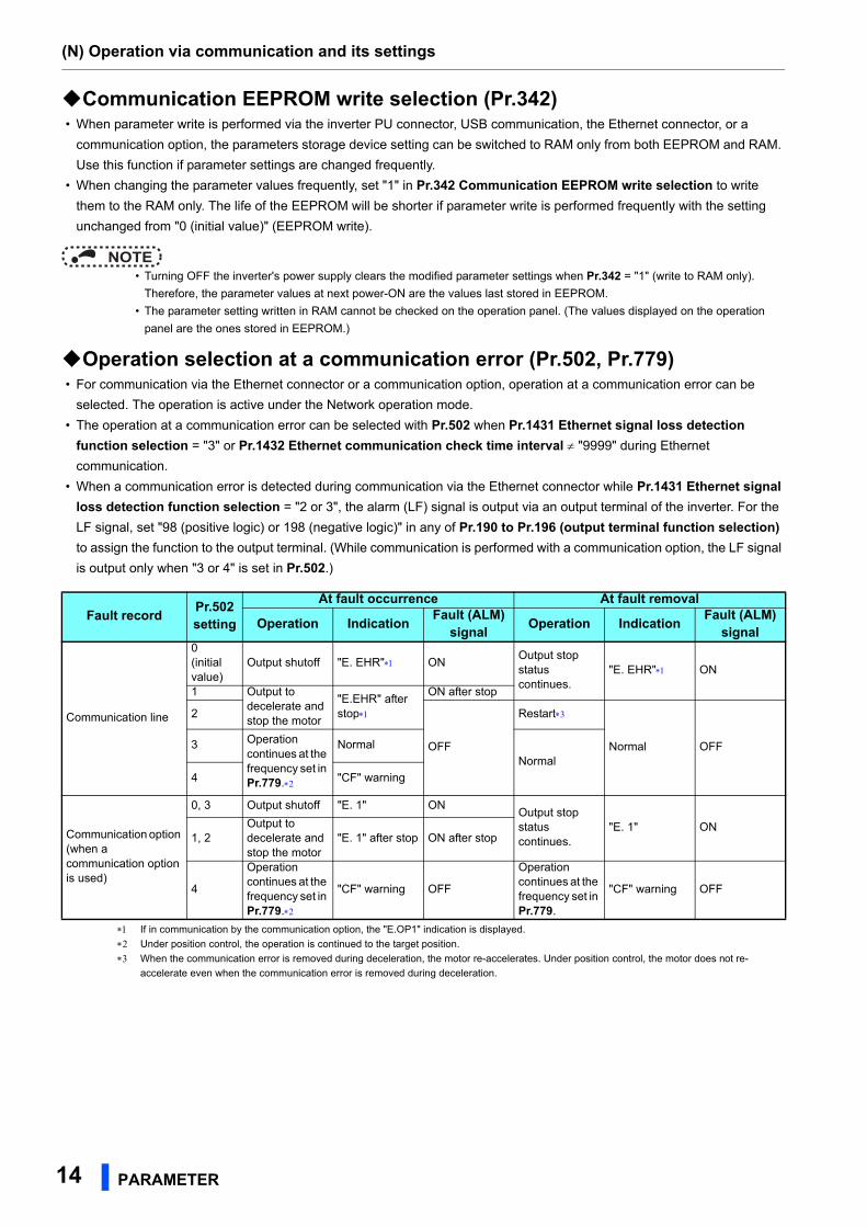
Communication EEPROM write selection (Pr.342) • When parameter write is performed via the inverter PU connector, USB communication, the Ethernet connector, or a
communication option, the parameters storage device setting can be switched to RAM only from both EEPROM and RAM.
Use this function if parameter settings are changed frequently.
• When changing the parameter values frequently, set "1" in Pr.342 Communication EEPROM write selection to write
them to the RAM only. The life of the EEPROM will be shorter if parameter write is performed frequently with the setting
unchanged from "0 (initial value)" (EEPROM write).
NOTE • Turning OFF the inverter's power supply clears the modified parameter settings when Pr.342 = "1" (write to RAM only).
Therefore, the parameter values at next power-ON are the values last stored in EEPROM.
• The parameter setting written in RAM cannot be checked on the operation panel. (The values displayed on the operation
panel are the ones stored in EEPROM.)
Operation selection at a communication error (Pr.502, Pr.779) • For communication via the Ethernet connector or a communication option, operation at a communication error can be
selected. The operation is active under the Network operation mode.
• The operation at a communication error can be selected with Pr.502 when Pr.1431 Ethernet signal loss detection
function selection = "3" or Pr.1432 Ethernet communication check time interval "9999" during Ethernet
communication.
• When a communication error is detected during communication via the Ethernet connector while Pr.1431 Ethernet signal
loss detection function selection = "2 or 3", the alarm (LF) signal is output via an output terminal of the inverter. For the
LF signal, set "98 (positive logic) or 198 (negative logic)" in any of Pr.190 to Pr.196 (output terminal function selection)
to assign the function to the output terminal. (While communication is performed with a communication option, the LF signal
is output only when "3 or 4" is set in Pr.502.)
If in communication by the communication option, the "E.OP1" indication is displayed.
Under position control, the operation is continued to the target position.
When the communication error is removed during deceleration, the motor re-accelerates. Under position control, the motor does not re-
accelerate even when the communication error is removed during deceleration.
Fault recordPr.502 setting
At fault occurrence At fault removal
Operation IndicationFault (ALM)
signalOperation Indication
Fault (ALM) signal
Communication line
0(initial value)
Output shutoff "E. EHR" ONOutput stop status continues.
"E. EHR" ON
1 Output to decelerate and stop the motor
"E.EHR" after stop
ON after stop
2
OFF
Restart
Normal OFF3 Operation continues at the frequency set in Pr.779.
Normal
Normal
4 "CF" warning
Communication option (when a communication option is used)
0, 3 Output shutoff "E. 1" ONOutput stop status continues.
"E. 1" ON1, 2
Output to decelerate and stop the motor
"E. 1" after stop ON after stop
4
Operation continues at the frequency set in Pr.779.
"CF" warning OFF
Operation continues at the frequency set in Pr.779.
"CF" warning OFF
(N) Operation via communication and its settings
PARAMETER 15
2
GROUP
N
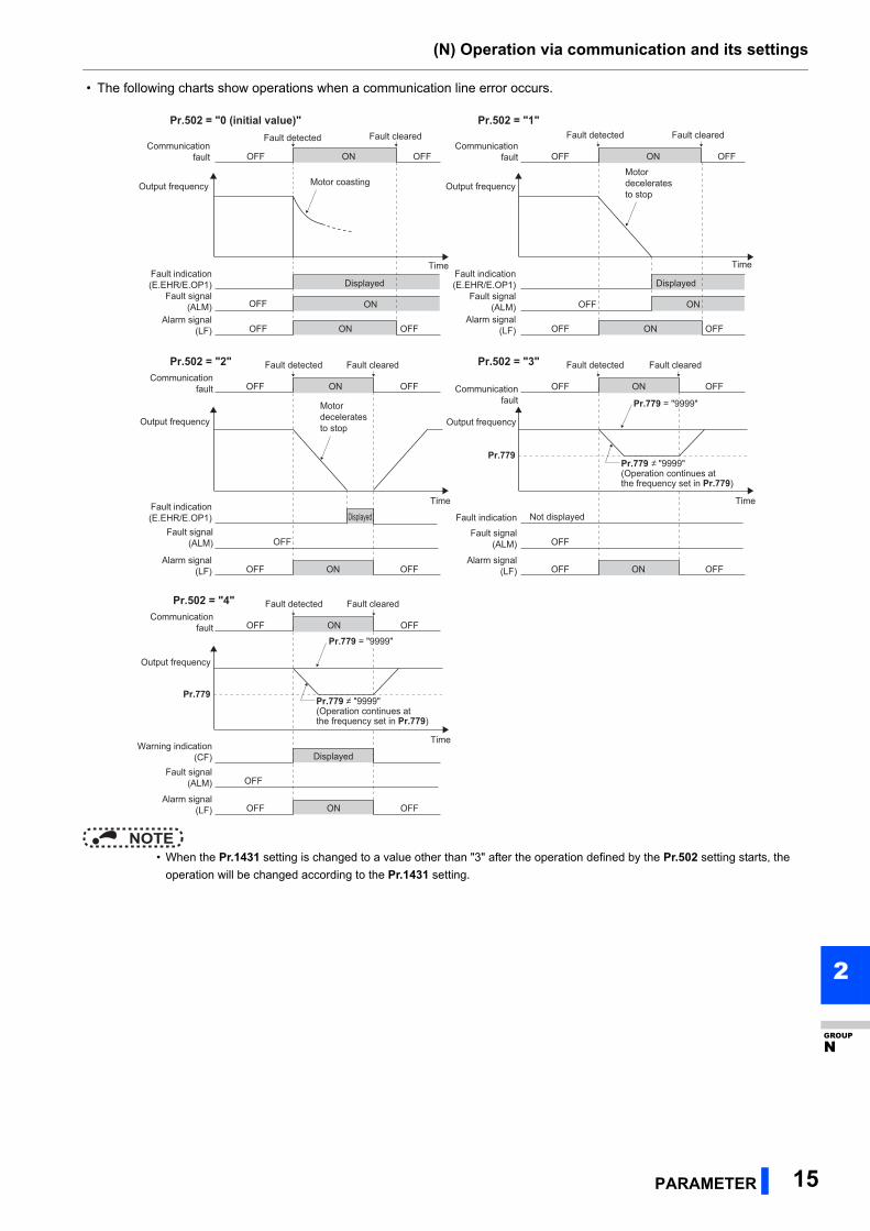
• The following charts show operations when a communication line error occurs.
NOTE • When the Pr.1431 setting is changed to a value other than "3" after the operation defined by the Pr.502 setting starts, the
operation will be changed according to the Pr.1431 setting.
Time
Motor coasting
Communication fault
Output frequency
Fault indication (E.EHR/E.OP1)
Fault indication (E.EHR/E.OP1)
Fault indication (E.EHR/E.OP1)
Fault signal (ALM)
ONOFF OFF
Displayed
ONOFF
Fault detected Fault cleared
Time
Communication fault
Output frequency
Fault signal (ALM)
ONOFF OFF
Displayed
ONOFF
Motor decelerates to stop
Fault detected Fault clearedPr.502 = "0 (initial value)" Pr.502 = "1"
Pr.502 = "2" Pr.502 = "3"
Time
Communication fault
Output frequency
Fault signal (ALM)
ONOFF OFF
Alarm signal (LF) ONOFF OFF
Alarm signal (LF) ONOFF OFF
Alarm signal (LF) ONOFF OFF
Alarm signal (LF) ONOFF OFF
Displayed
OFF
Motor decelerates to stop
Fault detected Fault cleared
Time
Communication fault
Output frequency
Fault indicationFault signal
(ALM)
ONOFF OFF
OFF
Fault detected Fault cleared
Pr.779 = "9999"Pr.779 = "9999"Pr.779 = "9999"
Pr.779 "9999" (Operation continues at the frequency set in Pr.779)
Not displayed
Pr.779
Pr.502 = "4"
Alarm signal (LF) ONOFF OFF
Displayed
Time
Communication fault
Output frequency
Warning indication (CF)
Fault signal (ALM)
ONOFF OFF
OFF
Fault detected Fault cleared
Pr.779 = "9999"Pr.779 = "9999"Pr.779 = "9999"
Pr.779 "9999" (Operation continues at the frequency set in Pr.779)
Pr.779
(N) Operation via communication and its settings
16 PARAMETER
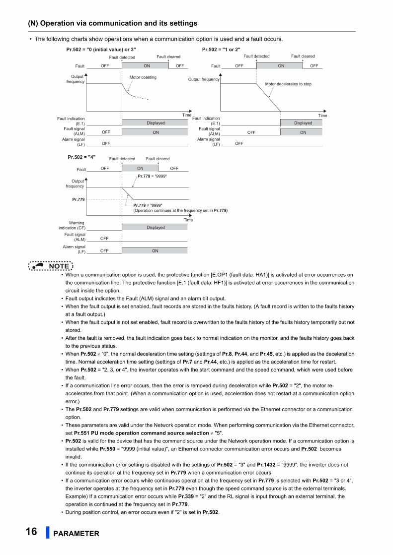
• The following charts show operations when a communication option is used and a fault occurs.
NOTE • When a communication option is used, the protective function [E.OP1 (fault data: HA1)] is activated at error occurrences on
the communication line. The protective function [E.1 (fault data: HF1)] is activated at error occurrences in the communication
circuit inside the option.
• Fault output indicates the Fault (ALM) signal and an alarm bit output.
• When the fault output is set enabled, fault records are stored in the faults history. (A fault record is written to the faults history
at a fault output.)
• When the fault output is not set enabled, fault record is overwritten to the faults history of the faults history temporarily but not
stored.
• After the fault is removed, the fault indication goes back to normal indication on the monitor, and the faults history goes back
to the previous status.
• When Pr.502 "0", the normal deceleration time setting (settings of Pr.8, Pr.44, and Pr.45, etc.) is applied as the deceleration
time. Normal acceleration time setting (settings of Pr.7 and Pr.44, etc.) is applied as the acceleration time for restart.
• When Pr.502 = "2, 3, or 4", the inverter operates with the start command and the speed command, which were used before
the fault.
• If a communication line error occurs, then the error is removed during deceleration while Pr.502 = "2", the motor re-
accelerates from that point. (When a communication option is used, acceleration does not restart at a communication option
error.)
• The Pr.502 and Pr.779 settings are valid when communication is performed via the Ethernet connector or a communication
option.
• These parameters are valid under the Network operation mode. When performing communication via the Ethernet connector,
set Pr.551 PU mode operation command source selection "5".
• Pr.502 is valid for the device that has the command source under the Network operation mode. If a communication option is
installed while Pr.550 = "9999 (initial value)", an Ethernet connector communication error occurs and Pr.502 becomes
invalid.
• If the communication error setting is disabled with the settings of Pr.502 = "3" and Pr.1432 = "9999", the inverter does not
continue its operation at the frequency set in Pr.779 when a communication error occurs.
• If a communication error occurs while continuous operation at the frequency set in Pr.779 is selected with Pr.502 = "3 or 4",
the inverter operates at the frequency set in Pr.779 even though the speed command source is at the external terminals.
Example) If a communication error occurs while Pr.339 = "2" and the RL signal is input through an external terminal, the
operation is continued at the frequency set in Pr.779.
• During position control, an error occurs even if "2" is set in Pr.502.
Time
Motor coasting
Fault
Output frequency
Fault indication (E.1)
Fault signal (ALM)
ONOFF OFF
Displayed
ONOFF
Fault detected Fault cleared
Time
Fault
Output frequency
Fault indication (E.1)
Fault signal (ALM)
ONOFF OFF
Displayed
ONOFF
Motor decelerates to stop
Fault detected Fault clearedPr.502 = "0 (initial value) or 3" Pr.502 = "1 or 2"
Alarm signal (LF) OFF
Alarm signal (LF) OFF
Pr.502 = "4"
Alarm signal (LF) ONOFF
Displayed
Time
Fault
Output frequency
Warning indication (CF)
Fault signal (ALM)
ONOFF OFF
OFF
Fault detected Fault cleared
Pr.779 = "9999"Pr.779 = "9999"Pr.779 = "9999"
Pr.779 "9999" (Operation continues at the frequency set in Pr.779)
Pr.779
(N) Operation via communication and its settings
PARAMETER 17
2
GROUP
N
Operation mode switching and communication startup mode (Pr.79, Pr.340)
• Check the following before switching the operation mode.
- The inverter is at a stop.
- Both the STF and STR signals are off.
- The Pr.79 Operation mode selection setting is correct. (Check the setting on the operation panel of the inverter.)
• The operation mode at power ON and at restoration from instantaneous power failure can be selected. Set a value other
than "0" in Pr.340 Communication startup mode selection to select the Network operation mode.
• After the inverter starts up in the Network operation mode, parameter write can be commanded via the network.
NOTE • The changed value in Pr.340 is applied after the next power-ON or inverter reset. • The Pr.340 setting can be changed on the operation panel in any operation mode. • When setting a value other than "0" in Pr.340, make sure that the communication settings of the inverter are correct.
Parameters referred to
Pr.7 Acceleration time, Pr.8 Deceleration time Instruction Manual (Detailed) of the FR-A800 inverter
Pr.79 Operation mode selection Instruction Manual (Detailed) of the FR-A800 inverter
Pr.340 Communication startup mode selection Instruction Manual (Detailed) of the FR-A800 inverter
Pr.550 NET mode operation command source selection page 9
Pr.551 PU mode operation command source selection page 9
Pr.1431 Ethernet signal loss detection function selection page 18
Pr.1432 Ethernet communication check time interval page 18
Caution When Pr.502 = "3" and a communication line error occurs, or Pr.502 = "4" and a communication line
error or a communication option fault occurs, the operation continues. When setting "3 or 4" in
Pr.502, provide a safety stop countermeasure other than via communication. For example, input a
signal (RES, MRS, or X92) through an external terminal or press the PU stop on the operation panel.
(N) Operation via communication and its settings
18 PARAMETER
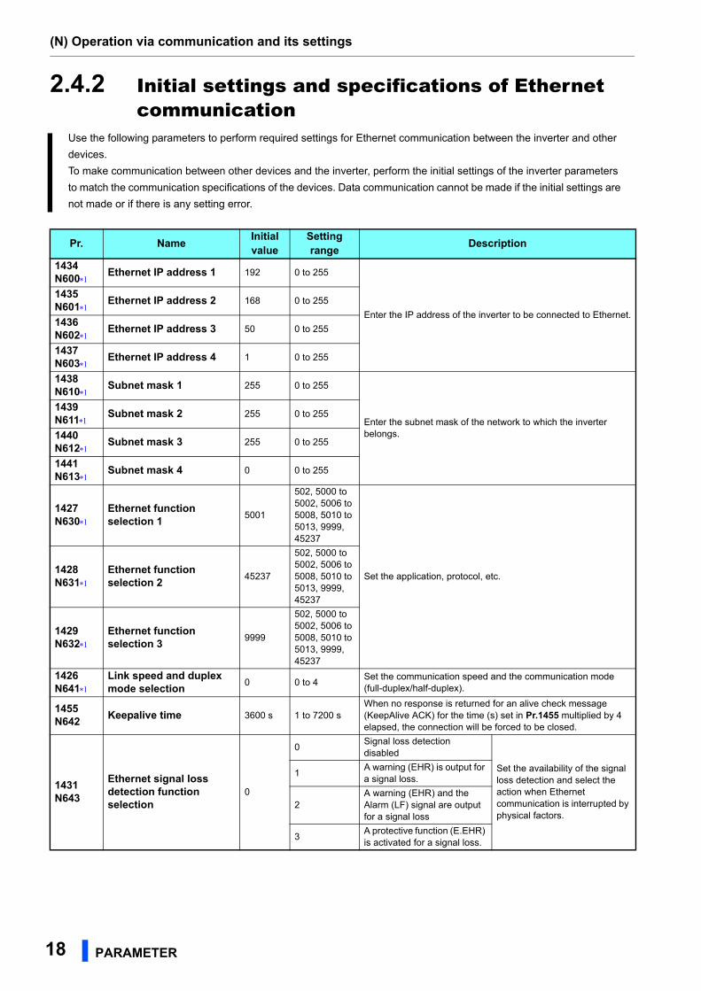
2.4.2 Initial settings and specifications of Ethernet communication
Use the following parameters to perform required settings for Ethernet communication between the inverter and other
devices.
To make communication between other devices and the inverter, perform the initial settings of the inverter parameters
to match the communication specifications of the devices. Data communication cannot be made if the initial settings are
not made or if there is any setting error.
Pr. NameInitial value
Setting range
Description
1434N600
Ethernet IP address 1 192 0 to 255
Enter the IP address of the inverter to be connected to Ethernet.
1435N601
Ethernet IP address 2 168 0 to 255
1436N602
Ethernet IP address 3 50 0 to 255
1437N603
Ethernet IP address 4 1 0 to 255
1438N610
Subnet mask 1 255 0 to 255
Enter the subnet mask of the network to which the inverter belongs.
1439N611
Subnet mask 2 255 0 to 255
1440N612
Subnet mask 3 255 0 to 255
1441N613
Subnet mask 4 0 0 to 255
1427N630
Ethernet function selection 1
5001
502, 5000 to 5002, 5006 to 5008, 5010 to 5013, 9999, 45237
Set the application, protocol, etc.1428N631
Ethernet function selection 2
45237
502, 5000 to 5002, 5006 to 5008, 5010 to 5013, 9999, 45237
1429N632
Ethernet function selection 3
9999
502, 5000 to 5002, 5006 to 5008, 5010 to 5013, 9999, 45237
1426N641
Link speed and duplex mode selection
0 0 to 4Set the communication speed and the communication mode (full-duplex/half-duplex).
1455N642
Keepalive time 3600 s 1 to 7200 sWhen no response is returned for an alive check message (KeepAlive ACK) for the time (s) set in Pr.1455 multiplied by 4 elapsed, the connection will be forced to be closed.
1431N643
Ethernet signal loss detection function selection
0
0Signal loss detection disabled
Set the availability of the signal loss detection and select the action when Ethernet communication is interrupted by physical factors.
1A warning (EHR) is output for a signal loss.
2A warning (EHR) and the Alarm (LF) signal are output for a signal loss
3A protective function (E.EHR) is activated for a signal loss.
(N) Operation via communication and its settings
PARAMETER 19
2
GROUP
N
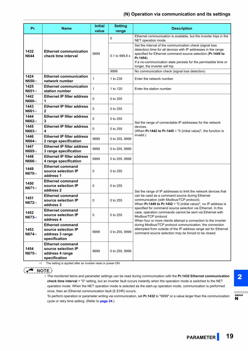
The setting is applied after an inverter reset or power-ON.
NOTE • The monitored items and parameter settings can be read during communication with the Pr.1432 Ethernet communication
check time interval = "0" setting, but an inverter fault occurs instantly when the operation mode is switched to the NET
operation mode. When the NET operation mode is selected as the start-up operation mode, communication is performed
once, then an Ethernet communication fault (E.EHR) occurs.
To perform operation or parameter writing via communication, set Pr.1432 to "9999" or a value larger than the communication
cycle or retry time setting. (Refer to page 24.)
1432N644
Ethernet communication check time interval
9999
0Ethernet communication is available, but the inverter trips in the NET operation mode.
0.1 to 999.8 s
Set the interval of the communication check (signal loss detection) time for all devices with IP addresses in the range specified for Ethernet command source selection (Pr.1449 to Pr.1454).If a no-communication state persists for the permissible time or longer, the inverter will trip.
9999 No communication check (signal loss detection)
1424N650
Ethernet communication network number
1 1 to 239 Enter the network number.
1425N651
Ethernet communication station number
1 1 to 120 Enter the station number.
1442N660
Ethernet IP filter address 1
0 0 to 255
Set the range of connectable IP addresses for the network devices.(When Pr.1442 to Pr.1445 = "0 (initial value)", the function is invalid.)
1443N661
Ethernet IP filter address 2
0 0 to 255
1444N662
Ethernet IP filter address 3
0 0 to 255
1445N663
Ethernet IP filter address 4
0 0 to 255
1446N664
Ethernet IP filter address 2 range specification
9999 0 to 255, 9999
1447N665
Ethernet IP filter address 3 range specification
9999 0 to 255, 9999
1448N666
Ethernet IP filter address 4 range specification
9999 0 to 255, 9999
1449N670
Ethernet command source selection IP address 1
0 0 to 255
Set the range of IP addresses to limit the network devices that can be used as a command source during Ethernet communication (with Modbus/TCP protocol).When Pr.1449 to Pr.1452 = "0 (initial value)", no IP address is specified for command source selection via Ethernet. In this case, operation commands cannot be sent via Ethernet with Modbus/TCP protocol.When four or more clients attempt a connection to the inverter during Modbus/TCP protocol communication, the connection attempted from outside of the IP address range set for Ethernet command source selection may be forced to be closed.
1450N671
Ethernet command source selection IP address 2
0 0 to 255
1451N672
Ethernet command source selection IP address 3
0 0 to 255
1452N673
Ethernet command source selection IP address 4
0 0 to 255
1453N674
Ethernet command source selection IP address 3 range specification
9999 0 to 255, 9999
1454N675
Ethernet command source selection IP address 4 range specification
9999 0 to 255, 9999
Pr. NameInitial value
Setting range
Description
(N) Operation via communication and its settings
20 PARAMETER
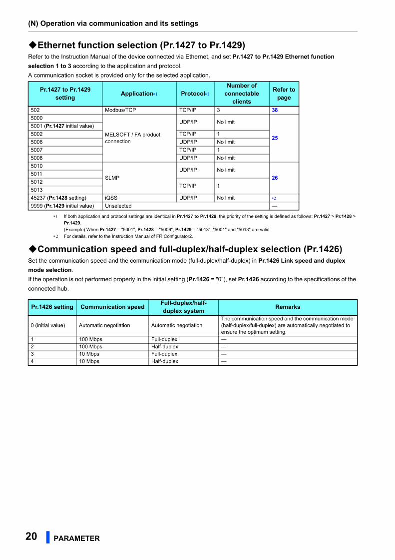
Ethernet function selection (Pr.1427 to Pr.1429)Refer to the Instruction Manual of the device connected via Ethernet, and set Pr.1427 to Pr.1429 Ethernet function
selection 1 to 3 according to the application and protocol.
A communication socket is provided only for the selected application.
If both application and protocol settings are identical in Pr.1427 to Pr.1429, the priority of the setting is defined as follows: Pr.1427 > Pr.1428 >
Pr.1429.
(Example) When Pr.1427 = "5001", Pr.1428 = "5006", Pr.1429 = "5013", "5001" and "5013" are valid.
For details, refer to the Instruction Manual of FR Configurator2.
Communication speed and full-duplex/half-duplex selection (Pr.1426)Set the communication speed and the communication mode (full-duplex/half-duplex) in Pr.1426 Link speed and duplex
mode selection.
If the operation is not performed properly in the initial setting (Pr.1426 = "0"), set Pr.1426 according to the specifications of the
connected hub.
Pr.1427 to Pr.1429setting
Application ProtocolNumber of
connectableclients
Refer topage
502 Modbus/TCP TCP/IP 3 38
5000
MELSOFT / FA product connection
UDP/IP No limit
25
5001 (Pr.1427 initial value)
5002 TCP/IP 1
5006 UDP/IP No limit
5007 TCP/IP 1
5008 UDP/IP No limit
5010
SLMP
UDP/IP No limit
265011
5012TCP/IP 1
5013
45237 (Pr.1428 setting) iQSS UDP/IP No limit
9999 (Pr.1429 initial value) Unselected —
Pr.1426 setting Communication speedFull-duplex/half-duplex system
Remarks
0 (initial value) Automatic negotiation Automatic negotiationThe communication speed and the communication mode (half-duplex/full-duplex) are automatically negotiated to ensure the optimum setting.
1 100 Mbps Full-duplex —2 100 Mbps Half-duplex —3 10 Mbps Full-duplex —4 10 Mbps Half-duplex —
(N) Operation via communication and its settings
PARAMETER 21
2
GROUP
N
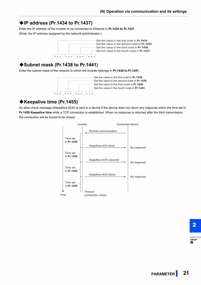
IP address (Pr.1434 to Pr.1437)Enter the IP address of the inverter to be connected to Ethernet in Pr.1434 to Pr.1437.
(Enter the IP address assigned by the network administrator.)
Subnet mask (Pr.1438 to Pr.1441)Enter the subnet mask of the network to which the inverter belongs in Pr.1438 to Pr.1441.
Keepalive time (Pr.1455)An alive check message (KeepAlive ACK) is sent to a device if the device does not return any response within the time set in
Pr.1455 Keepalive time while a TCP connection is established. When no response is returned after the third transmission,
the connection will be forced to be closed.
* * * . * * * . * * * . * * *
Set the value in the first octet in Pr.1434.Set the value in the second octet in Pr.1435.Set the value in the third octet in Pr.1436.Set the value in the fourth octet in Pr.1437.
* * * . * * * . * * * . * * *
Set the value in the first octet in Pr.1438.Set the value in the second octet in Pr.1439.Set the value in the third octet in Pr.1440.Set the value in the fourth octet in Pr.1441.
Inverter
KeepAlive ACK (first)
Normal communication
No response
No response
No response
Time set in Pr.1455
KeepAlive ACK (second)
KeepAlive ACK (third)
Timeout (connection close)
Connected device
Time set in Pr.1455
Time set in Pr.1455
Time set in Pr.1455
Time

(N) Operation via communication and its settings
22 PARAMETER
Ethernet IP filtering function (Pr.1442 to Pr.1448) • Set the IP address range for connectable network devices (Pr.1442 to Pr.1448) to limit the connectable devices. The IP
address setting range depends on the settings in Pr.1443 and Pr.1446, Pr.1444 and Pr.1447, and Pr.1445 and Pr.1448.
(Either of the settings can be larger than the other in Pr.1443 and Pr.1446, Pr.1444 and Pr.1447, and Pr.1445 and
Pr.1448.)
• When Pr.1442 to Pr.1445 = "0 (initial value)", the function is invalid.
• When Pr.1446 to Pr.1448 = "9999 (initial value)", the range is invalid.
Caution The Ethernet IP filtering function (Pr.1442 to Pr.1448) is provided as a means to prevent unauthorized
access (with intentions such as to corrupt programs or data) by external systems, but the function
does not prevent it completely. In order to protect the inverter and the system against unauthorized
access by external systems, take additional security measures. Mitsubishi Electric Corporation will
not take any responsibility for any problems in the inverter and the system incurred by unauthorized
access.
The following are examples of measures to prevent unauthorized access.
- Install a firewall.
- Install a personal computer as a relay station, and control the relaying of transmission data using
an application program.
- Install an external device as a relay station to control access rights. (For the details of external
devices used to control access rights, contact the distributors of the external devices.)
Ethernet IP address for filtering
In this case, the IP address range in which Ethernet communication is permitted is "192.168.x (1 to 3).xxx (100 to 150)".
[Setting example 1]
The range is between the values set in both parameters.
The range is between the values set in both parameters.
Pr.1442 Pr.1443 Pr.1444 Pr.1445
192 168 1 100
Filtering range setting for the Ethernet IP address
Pr.1446 Pr.1447 Pr.1448
― 9999 3 150
Ethernet IP address for filtering
In this case, the IP address range in which Ethernet communication is permitted is "192.168.2.xxx (50 to 100)".
[Setting example 2]Pr.1442 Pr.1443 Pr.1444 Pr.1445
192 168 2 100
Filtering range setting for the Ethernet IP address
Pr.1446 Pr.1447 Pr.1448
― 9999 9999 50
The range is between the values set in both parameters.
(N) Operation via communication and its settings
PARAMETER 23
2
GROUP
N
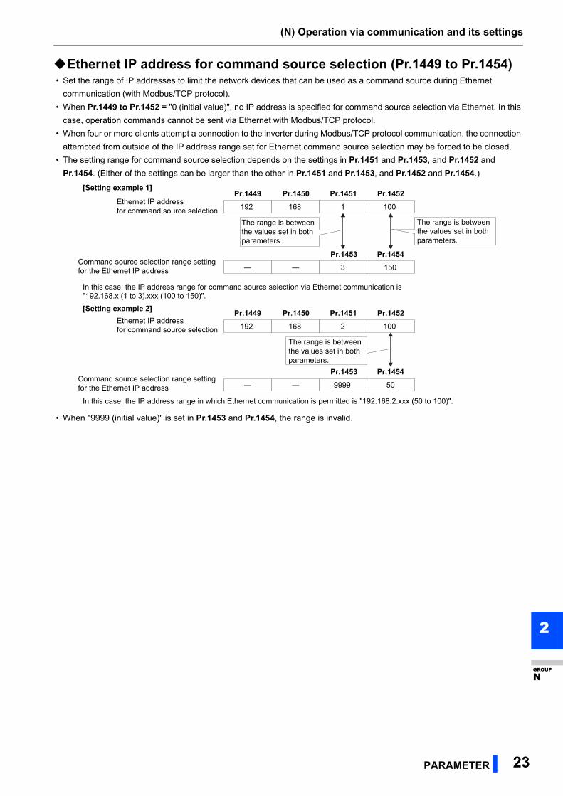
Ethernet IP address for command source selection (Pr.1449 to Pr.1454) • Set the range of IP addresses to limit the network devices that can be used as a command source during Ethernet
communication (with Modbus/TCP protocol).
• When Pr.1449 to Pr.1452 = "0 (initial value)", no IP address is specified for command source selection via Ethernet. In this
case, operation commands cannot be sent via Ethernet with Modbus/TCP protocol.
• When four or more clients attempt a connection to the inverter during Modbus/TCP protocol communication, the connection
attempted from outside of the IP address range set for Ethernet command source selection may be forced to be closed.
• The setting range for command source selection depends on the settings in Pr.1451 and Pr.1453, and Pr.1452 and
Pr.1454. (Either of the settings can be larger than the other in Pr.1451 and Pr.1453, and Pr.1452 and Pr.1454.)
• When "9999 (initial value)" is set in Pr.1453 and Pr.1454, the range is invalid.
Ethernet IP address for command source selection
In this case, the IP address range in which Ethernet communication is permitted is "192.168.2.xxx (50 to 100)".
[Setting example 2]
The range is between the values set in both parameters.
Pr.1449 Pr.1450 Pr.1451 Pr.1452
192 168 2 100
Command source selection range setting for the Ethernet IP address
Pr.1453 Pr.1454
― ― 9999 50
Ethernet IP address for command source selection
In this case, the IP address range for command source selection via Ethernet communication is "192.168.x (1 to 3).xxx (100 to 150)".
[Setting example 1]
The range is between the values set in both parameters.
Pr.1449 Pr.1450 Pr.1451 Pr.1452
192 168 1 100
Command source selection range setting for the Ethernet IP address
Pr.1453 Pr.1454
― ― 3 150
The range is between the values set in both parameters.
(N) Operation via communication and its settings
24 PARAMETER
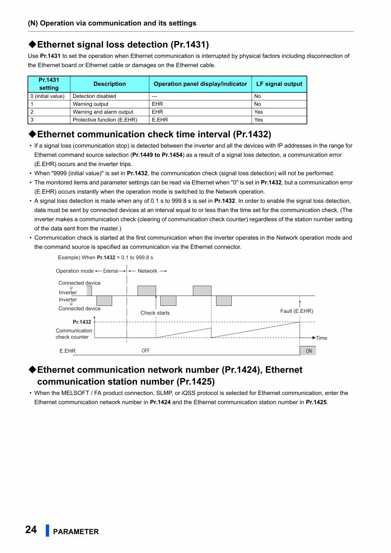
Ethernet signal loss detection (Pr.1431)Use Pr.1431 to set the operation when Ethernet communication is interrupted by physical factors including disconnection of
the Ethernet board or Ethernet cable or damages on the Ethernet cable.
Ethernet communication check time interval (Pr.1432) • If a signal loss (communication stop) is detected between the inverter and all the devices with IP addresses in the range for
Ethernet command source selection (Pr.1449 to Pr.1454) as a result of a signal loss detection, a communication error
(E.EHR) occurs and the inverter trips.
• When "9999 (initial value)" is set in Pr.1432, the communication check (signal loss detection) will not be performed.
• The monitored items and parameter settings can be read via Ethernet when "0" is set in Pr.1432, but a communication error
(E.EHR) occurs instantly when the operation mode is switched to the Network operation.
• A signal loss detection is made when any of 0.1 s to 999.8 s is set in Pr.1432. In order to enable the signal loss detection,
data must be sent by connected devices at an interval equal to or less than the time set for the communication check. (The
inverter makes a communication check (clearing of communication check counter) regardless of the station number setting
of the data sent from the master.)
• Communication check is started at the first communication when the inverter operates in the Network operation mode and
the command source is specified as communication via the Ethernet connector.
Ethernet communication network number (Pr.1424), Ethernet communication station number (Pr.1425)
• When the MELSOFT / FA product connection, SLMP, or iQSS protocol is selected for Ethernet communication, enter the
Ethernet communication network number in Pr.1424 and the Ethernet communication station number in Pr.1425.
Pr.1431setting
Description Operation panel display/indicator LF signal output
0 (initial value) Detection disabled — No
1 Warning output EHR No
2 Warning and alarm output EHR Yes
3 Protective function (E.EHR) E.EHR Yes
Connected device
Connected device
Operation mode
Example) When Pr.1432 = 0.1 to 999.8 s
External Network
Fault (E.EHR)
Time
InverterInverter
Communication check counter
Pr.1432Check starts
E.EHR OFF ON
(N) Operation via communication and its settings
PARAMETER 25
2
GROUP
N
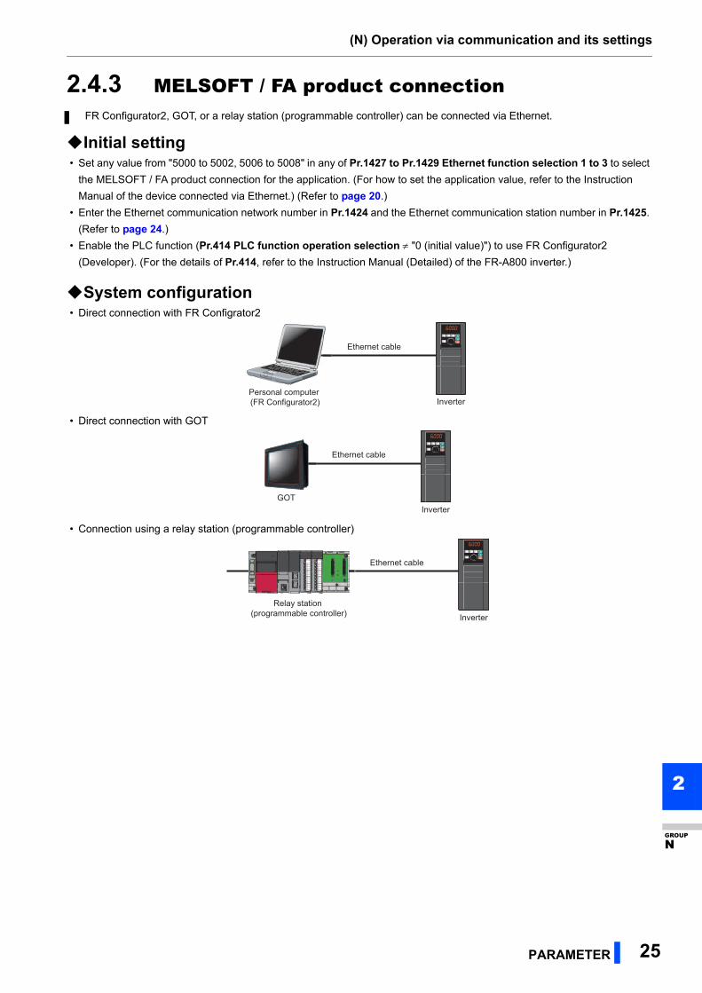
2.4.3 MELSOFT / FA product connection
Initial setting • Set any value from "5000 to 5002, 5006 to 5008" in any of Pr.1427 to Pr.1429 Ethernet function selection 1 to 3 to select
the MELSOFT / FA product connection for the application. (For how to set the application value, refer to the Instruction
Manual of the device connected via Ethernet.) (Refer to page 20.)
• Enter the Ethernet communication network number in Pr.1424 and the Ethernet communication station number in Pr.1425.
(Refer to page 24.)
• Enable the PLC function (Pr.414 PLC function operation selection "0 (initial value)") to use FR Configurator2
(Developer). (For the details of Pr.414, refer to the Instruction Manual (Detailed) of the FR-A800 inverter.)
System configuration • Direct connection with FR Configrator2
• Direct connection with GOT
• Connection using a relay station (programmable controller)
FR Configurator2, GOT, or a relay station (programmable controller) can be connected via Ethernet.
Personal computer (FR Configurator2)
Ethernet cable
Inverter
Ethernet cable
InverterGOT
Ethernet cable
Inverter
Relay station (programmable controller)
(N) Operation via communication and its settings
26 PARAMETER
2.4.4 SLMP
Initial setting • SLMP can be used when the PLC function is enabled. Set a value other than "0" in Pr.414 PLC function operation
selection.
• Set any value from "5010 to 5013" in any of Pr.1427 to Pr.1429 Ethernet function selection 1 to 3 to select SLMP for the
application. (For how to set the application value, refer to the Instruction Manual of the device connected via Ethernet.)
(Refer to page 20.)
• Enter the Ethernet communication network number in Pr.1424 and the Ethernet communication station number in Pr.1425.
(Refer to page 24.)
NOTE • The FR-A800-E inverter supports binary codes only. (ASCII codes are not supported.)
SLMP is a common protocol for seamless communication between applications. Users do not have to be concerned
with network layers or boundaries. SLMP communications are available among devices that can transfer messages by
SLMP (programmable controllers, personal computers, HMIs and others). (For the details of the SLMP compatibility of
external devices, refer to the Instruction Manual of external devices.)
(N) Operation via communication and its settings
PARAMETER 27
2
GROUP
N
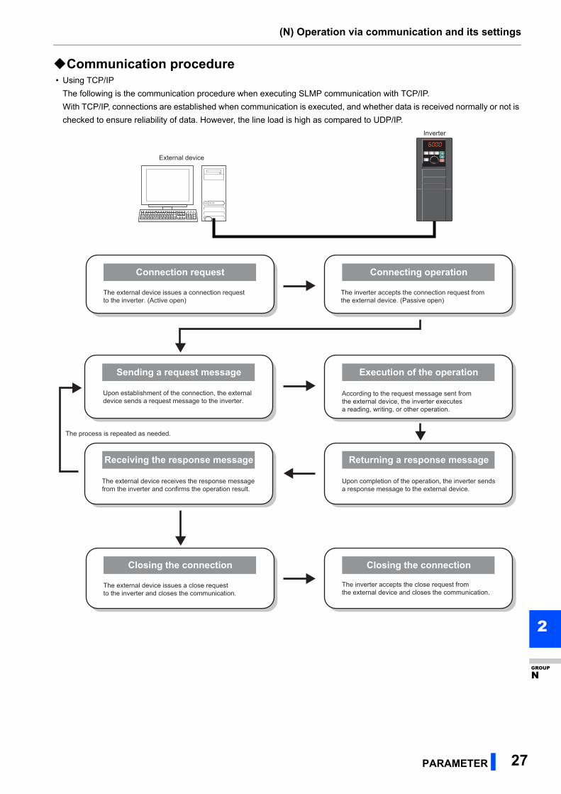
Communication procedure • Using TCP/IP
The following is the communication procedure when executing SLMP communication with TCP/IP.
With TCP/IP, connections are established when communication is executed, and whether data is received normally or not is
checked to ensure reliability of data. However, the line load is high as compared to UDP/IP.
External device
Inverter
The external device issues a connection request to the inverter. (Active open)
Connection request
The inverter accepts the connection request from the external device. (Passive open)
Connecting operation
According to the request message sent from the external device, the inverter executes a reading, writing, or other operation.
Execution of the operation
Upon establishment of the connection, the external device sends a request message to the inverter.
Sending a request message
The external device issues a close request to the inverter and closes the communication.
Closing the connection Closing the connection
Upon completion of the operation, the inverter sends a response message to the external device.
Returning a response message
The external device receives the response message from the inverter and confirms the operation result.
The process is repeated as needed.
Receiving the response message
The inverter accepts the close request from the external device and closes the communication.
(N) Operation via communication and its settings
28 PARAMETER
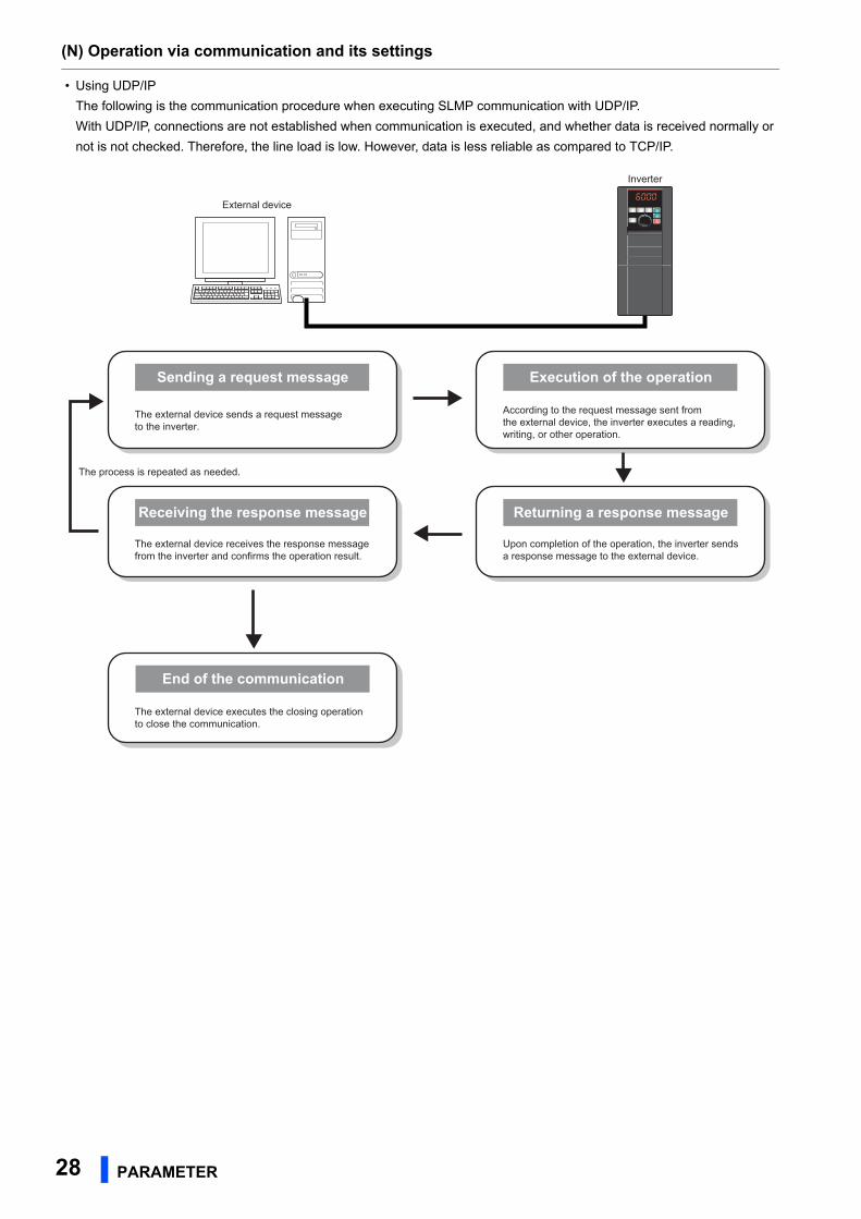
• Using UDP/IP
The following is the communication procedure when executing SLMP communication with UDP/IP.
With UDP/IP, connections are not established when communication is executed, and whether data is received normally or
not is not checked. Therefore, the line load is low. However, data is less reliable as compared to TCP/IP.
External device
Inverter
According to the request message sent from the external device, the inverter executes a reading, writing, or other operation.
Execution of the operation
The external device sends a request message to the inverter.
Sending a request message
Upon completion of the operation, the inverter sends a response message to the external device.
Returning a response message
The external device receives the response message from the inverter and confirms the operation result.
The process is repeated as needed.
Receiving the response message
The external device executes the closing operation to close the communication.
End of the communication
(N) Operation via communication and its settings
PARAMETER 29
2
GROUP
N
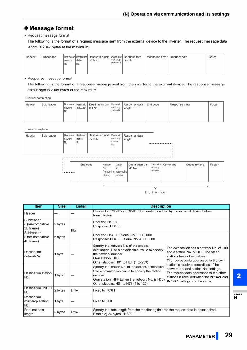
Message format • Request message format
The following is the format of a request message sent from the external device to the inverter. The request message data
length is 2047 bytes at the maximum.
• Response message format
The following is the format of a response message sent from the inverter to the external device. The response message
data length is 2048 bytes at the maximum.
Item Size Endian Description
Header — —Header for TCP/IP or UDP/IP. The header is added by the external device before transmission.
Subheader(QnA-compatible 3E frame)
2 bytes
Big
Request: H5000Response: HD000
Subheader(QnA-compatible 4E frame)
6 bytesRequest: H5400 + Serial No. + H0000Response: HD400 + Serial No. + H0000
Destination network No.
1 byte —
Specify the network No. of the access destination. Use a hexadecimal value to specify the network number.Own station: H00Other stations: H01 to HEF (1 to 239)
The own station has a network No. of H00 and a station No. of HFF. The other stations have other values.The request data addressed to the own station is received regardless of the network No. and station No. settings.The request data addressed to the other stations is received when the Pr.1424 and Pr.1425 settings are the same.
Destination station No.
1 byte —
Specify the station No. of the access destination.Use a hexadecimal value to specify the station number.Own station: HFF (when the network No. is H00)Other stations: H01 to H78 (1 to 120)
Destination unit I/O No.
2 bytes Little Fixed to H03FF
Destination multidrop station No.
1 byte — Fixed to H00
Request data length
2 bytes LittleSpecify the data length from the monitoring timer to the request data in hexadecimal.Example) 24 bytes: H1800
Destination unit I/O No.
Header Subheader Destination station No.
Destination network No.
Destination multidrop station No.
Request data length
Monitoring timer Request data Footer
Destination unit I/O No.
Header
• Normal completion
Subheader Destination station No.
Destination network No.
Destination multidrop station No.
Destination multidrop station No.
Destination multidrop station No.
Response data length
End code Response data Footer
Footer
Destination unit I/O No.
Header
• Failed completion
Subheader Destination station No.
Destination network No.
Response data length
Destination unit I/O No.
Station No. (responding station)
Network No. (responding station)
Error information
Command SubcommandEnd code
(N) Operation via communication and its settings
30 PARAMETER
The serial No. is given by the external device for message recognition. If a request message with a serial No. is sent, the same serial No. will
also be added on the response message. The serial No. is used when multiple request messages are sent from an external device to the same
inverter.
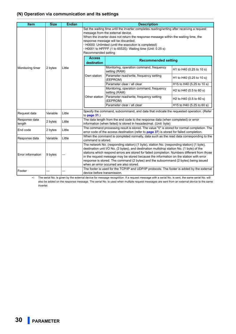
Monitoring timer 2 bytes Little
Set the waiting time until the inverter completes reading/writing after receiving a request message from the external device.When the inverter does not return the response message within the waiting time, the response message will be discarded. H0000: Unlimited (until the execution is completed) H0001 to HFFFF (1 to 65535): Waiting time (Unit: 0.25 s)Recommended setting
Request data Variable LittleSpecify the command, subcommand, and data that indicate the requested operation. (Refer to page 31.)
Response data length
2 bytes LittleThe data length from the end code to the response data (when completed) or error information (when failed) is stored in hexadecimal. (Unit: byte)
End code 2 bytes LittleThe command processing result is stored. The value "0" is stored for normal completion. The error code of the access destination (refer to page 37) is stored for failed completion.
Response data Variable LittleWhen the command is completed normally, data such as the read data corresponding to the command is stored.
Error information 9 bytes —
The network No. (responding station) (1 byte), station No. (responding station) (1 byte), destination unit I/O No. (2 bytes), and destination multidrop station No. (1 byte) of the stations which respond errors are stored for failed completion. Numbers different from those in the request message may be stored because the information on the station with error response is stored. The command (2 bytes) and the subcommand (2 bytes) being issued when an error occurred are also stored.
Footer — —The footer is used for the TCP/IP and UDP/IP protocols. The footer is added by the external device before transmission.
Item Size Endian Description
Access destination
Recommended setting
Own station
Monitoring, operation command, frequency setting (RAM)
H1 to H40 (0.25 to 10 s)
Parameter read/write, frequency setting (EEPROM)
H1 to H40 (0.25 to 10 s)
Parameter clear / all clear H15 to H40 (5.25 to 10 s)
Other station
Monitoring, operation command, frequency setting (RAM)
H2 to H40 (0.5 to 60 s)
Parameter read/write, frequency setting (EEPROM)
H2 to H40 (0.5 to 60 s)
Parameter clear / all clear H15 to H40 (5.25 to 60 s)
(N) Operation via communication and its settings
PARAMETER 31
2
GROUP
N
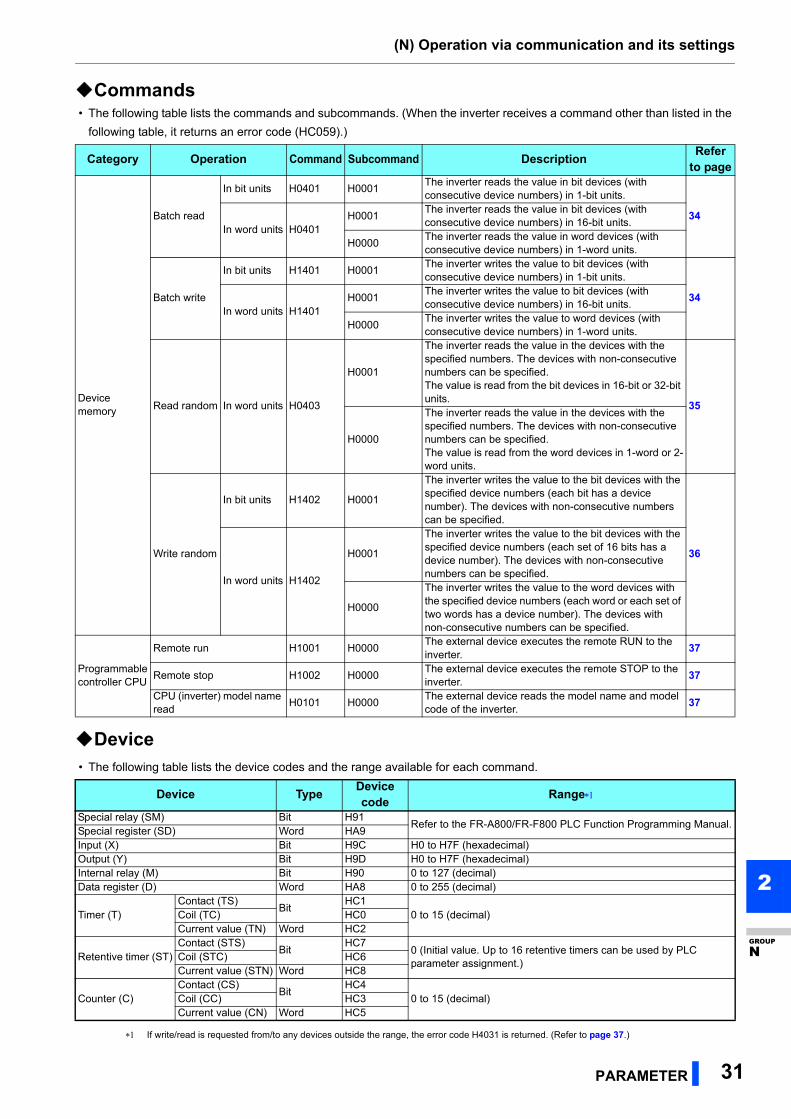
Commands • The following table lists the commands and subcommands. (When the inverter receives a command other than listed in the
following table, it returns an error code (HC059).)
Device • The following table lists the device codes and the range available for each command.
If write/read is requested from/to any devices outside the range, the error code H4031 is returned. (Refer to page 37.)
Category Operation Command Subcommand DescriptionRefer
to page
Device memory
Batch read
In bit units H0401 H0001The inverter reads the value in bit devices (with consecutive device numbers) in 1-bit units.
34In word units H0401
H0001The inverter reads the value in bit devices (with consecutive device numbers) in 16-bit units.
H0000The inverter reads the value in word devices (with consecutive device numbers) in 1-word units.
Batch write
In bit units H1401 H0001The inverter writes the value to bit devices (with consecutive device numbers) in 1-bit units.
34In word units H1401
H0001The inverter writes the value to bit devices (with consecutive device numbers) in 16-bit units.
H0000The inverter writes the value to word devices (with consecutive device numbers) in 1-word units.
Read random In word units H0403
H0001
The inverter reads the value in the devices with the specified numbers. The devices with non-consecutive numbers can be specified.The value is read from the bit devices in 16-bit or 32-bit units.
35
H0000
The inverter reads the value in the devices with the specified numbers. The devices with non-consecutive numbers can be specified.The value is read from the word devices in 1-word or 2-word units.
Write random
In bit units H1402 H0001
The inverter writes the value to the bit devices with the specified device numbers (each bit has a device number). The devices with non-consecutive numbers can be specified.
36
In word units H1402
H0001
The inverter writes the value to the bit devices with the specified device numbers (each set of 16 bits has a device number). The devices with non-consecutive numbers can be specified.
H0000
The inverter writes the value to the word devices with the specified device numbers (each word or each set of two words has a device number). The devices with non-consecutive numbers can be specified.
Programmable controller CPU
Remote run H1001 H0000The external device executes the remote RUN to the inverter.
37
Remote stop H1002 H0000The external device executes the remote STOP to the inverter.
37
CPU (inverter) model name read
H0101 H0000The external device reads the model name and model code of the inverter.
37
Device TypeDevice code
Range
Special relay (SM) Bit H91Refer to the FR-A800/FR-F800 PLC Function Programming Manual.
Special register (SD) Word HA9Input (X) Bit H9C H0 to H7F (hexadecimal)Output (Y) Bit H9D H0 to H7F (hexadecimal)Internal relay (M) Bit H90 0 to 127 (decimal)Data register (D) Word HA8 0 to 255 (decimal)
Timer (T)Contact (TS)
BitHC1
0 to 15 (decimal)Coil (TC) HC0Current value (TN) Word HC2
Retentive timer (ST)Contact (STS)
BitHC7
0 (Initial value. Up to 16 retentive timers can be used by PLC parameter assignment.)
Coil (STC) HC6Current value (STN) Word HC8
Counter (C)Contact (CS)
BitHC4
0 to 15 (decimal)Coil (CC) HC3Current value (CN) Word HC5
(N) Operation via communication and its settings
32 PARAMETER
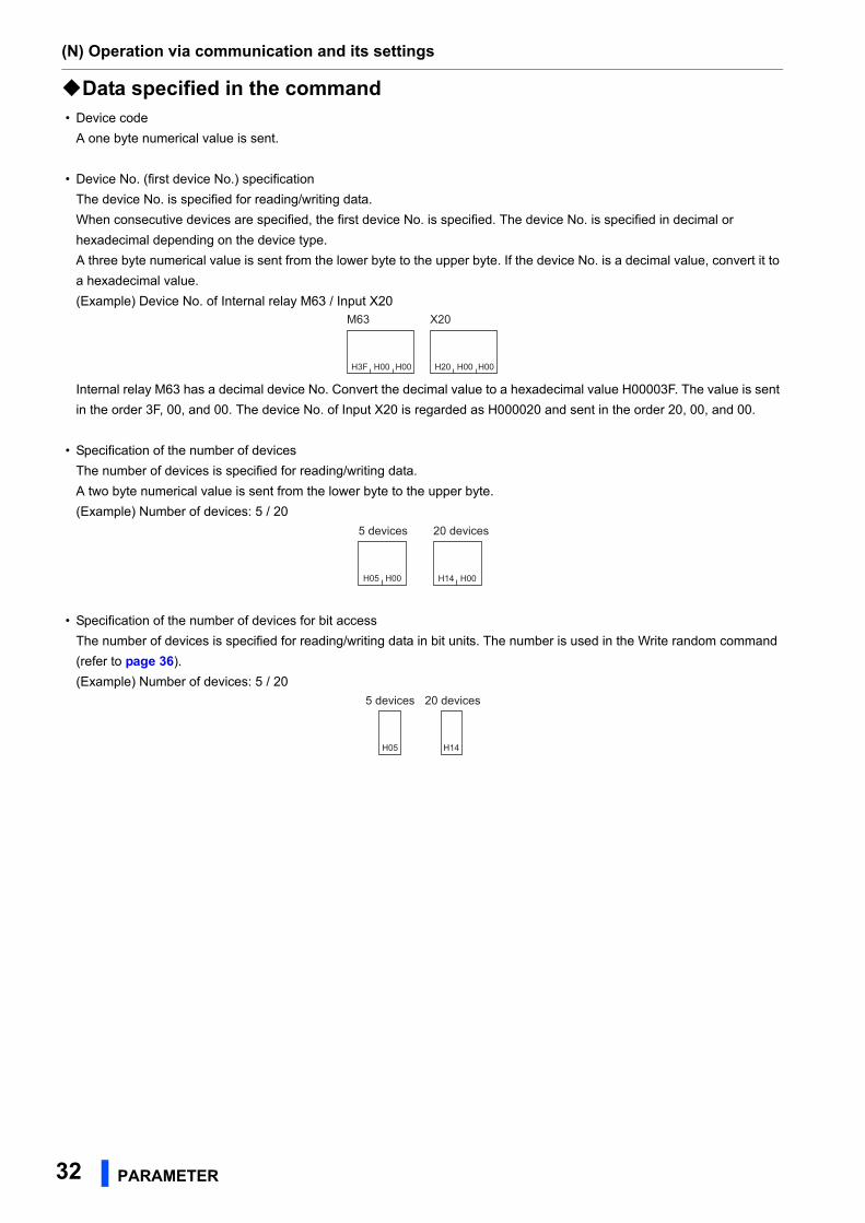
Data specified in the command • Device code
A one byte numerical value is sent.
• Device No. (first device No.) specification
The device No. is specified for reading/writing data.
When consecutive devices are specified, the first device No. is specified. The device No. is specified in decimal or
hexadecimal depending on the device type.
A three byte numerical value is sent from the lower byte to the upper byte. If the device No. is a decimal value, convert it to
a hexadecimal value.
(Example) Device No. of Internal relay M63 / Input X20
Internal relay M63 has a decimal device No. Convert the decimal value to a hexadecimal value H00003F. The value is sent
in the order 3F, 00, and 00. The device No. of Input X20 is regarded as H000020 and sent in the order 20, 00, and 00.
• Specification of the number of devices
The number of devices is specified for reading/writing data.
A two byte numerical value is sent from the lower byte to the upper byte.
(Example) Number of devices: 5 / 20
• Specification of the number of devices for bit access
The number of devices is specified for reading/writing data in bit units. The number is used in the Write random command
(refer to page 36).
(Example) Number of devices: 5 / 20
H3F H00
M63
H00 H20 H00 H00
X20
H05 H00 H14 H00
5 devices 20 devices
H05 H14
5 devices 20 devices
(N) Operation via communication and its settings
PARAMETER 33
2
GROUP
N
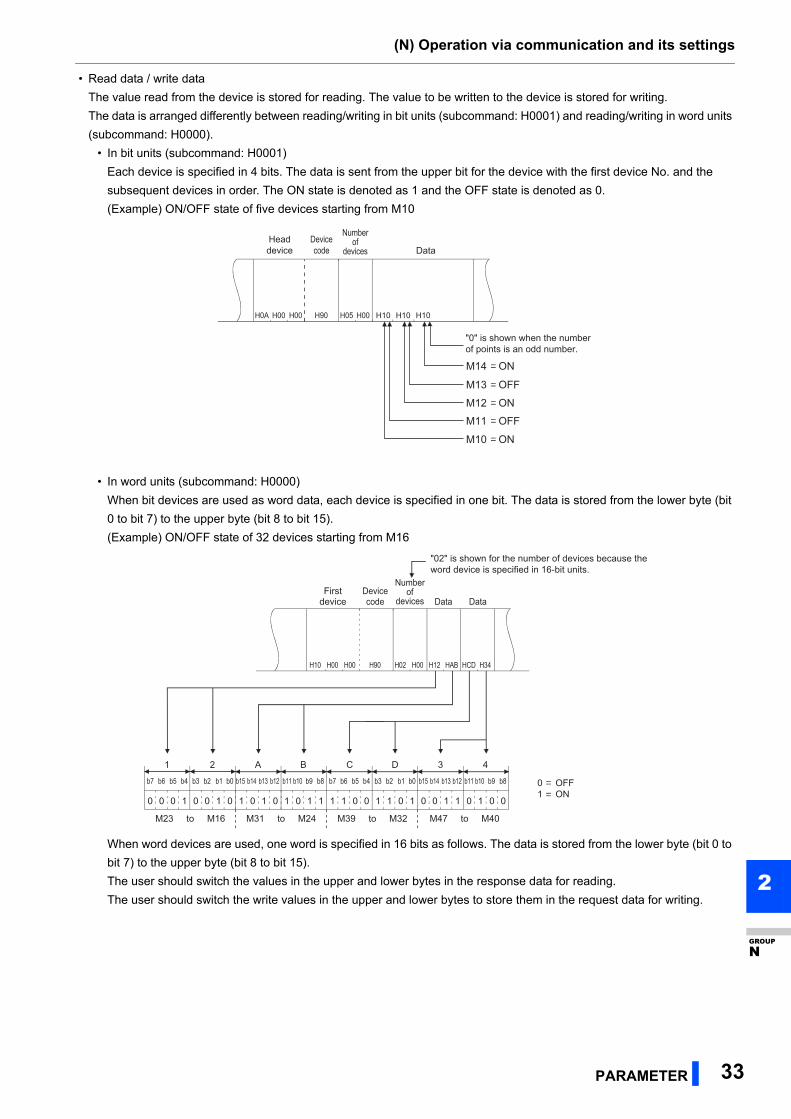
• Read data / write data
The value read from the device is stored for reading. The value to be written to the device is stored for writing.
The data is arranged differently between reading/writing in bit units (subcommand: H0001) and reading/writing in word units
(subcommand: H0000).
• In bit units (subcommand: H0001)
Each device is specified in 4 bits. The data is sent from the upper bit for the device with the first device No. and the
subsequent devices in order. The ON state is denoted as 1 and the OFF state is denoted as 0.
(Example) ON/OFF state of five devices starting from M10
• In word units (subcommand: H0000)
When bit devices are used as word data, each device is specified in one bit. The data is stored from the lower byte (bit
0 to bit 7) to the upper byte (bit 8 to bit 15).
(Example) ON/OFF state of 32 devices starting from M16
When word devices are used, one word is specified in 16 bits as follows. The data is stored from the lower byte (bit 0 to
bit 7) to the upper byte (bit 8 to bit 15).
The user should switch the values in the upper and lower bytes in the response data for reading.
The user should switch the write values in the upper and lower bytes to store them in the request data for writing.
H0A H00 H00 H90 H05 H00 H10 H10 H10
M14 ON
M13 OFF
M12 ON
M11 OFF
M10 ON
Devicecode
Numberof
devices Data
"0" is shown when the number of points is an odd number.
Headdevice
H10 H00 H00 H90 H02 H00 H12 HAB HCD H34
0 0 0 1 0 0 1 0 1 0 1 0 1 0 1 1 1 1 0 0
b11 b10 b9 b8b7 b6 b5 b4 b3 b2 b1 b0
1 1 0 1 0 0 1 1 0 1 0 0
b9 b8b7 b6 b5 b4 b3 b2 b1 b0b15 b14 b13 b12 b11 b10b15 b14 b13 b12
1 2 A B C D 3 4
0 OFF1 ON
M23 to M16 M31 to M24 M39 to M32 M47 to M40
"02" is shown for the number of devices because the word device is specified in 16-bit units.
Number of
devices DataDataFirst
deviceDevice code
(N) Operation via communication and its settings
34 PARAMETER
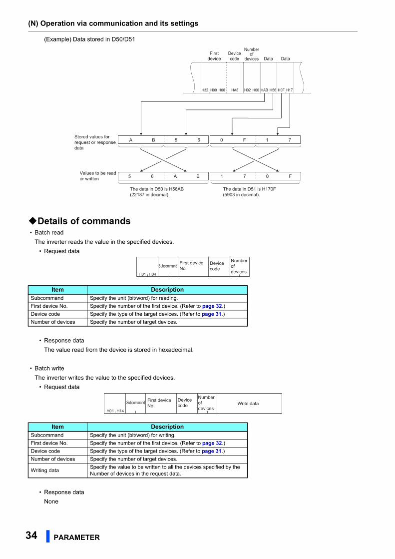
(Example) Data stored in D50/D51
Details of commands • Batch read
The inverter reads the value in the specified devices.
• Request data
• Response data
The value read from the device is stored in hexadecimal.
• Batch write
The inverter writes the value to the specified devices.
• Request data
• Response data
None
Item DescriptionSubcommand Specify the unit (bit/word) for reading.
First device No. Specify the number of the first device. (Refer to page 32.)
Device code Specify the type of the target devices. (Refer to page 31.)
Number of devices Specify the number of target devices.
Item DescriptionSubcommand Specify the unit (bit/word) for writing.
First device No. Specify the number of the first device. (Refer to page 32.)
Device code Specify the type of the target devices. (Refer to page 31.)
Number of devices Specify the number of target devices.
Writing dataSpecify the value to be written to all the devices specified by the Number of devices in the request data.
A B 5 6 0 F 1 7
5 6 A B 1 7 0 F
H32 H00 H00 HA8 H02 H00 HAB H56 H0F H17
The data in D51 is H170F (5903 in decimal).
Values to be read or written
Stored values for request or response data
The data in D50 is H56AB (22187 in decimal).
DataData
Number of
devicesDevice code
First device
H01 H04
SubcommandNumber of devices
Device code
First device No.
H01 H14
SubcommandNumber of devices
Device code
First device No. Write data
(N) Operation via communication and its settings
PARAMETER 35
2
GROUP
N
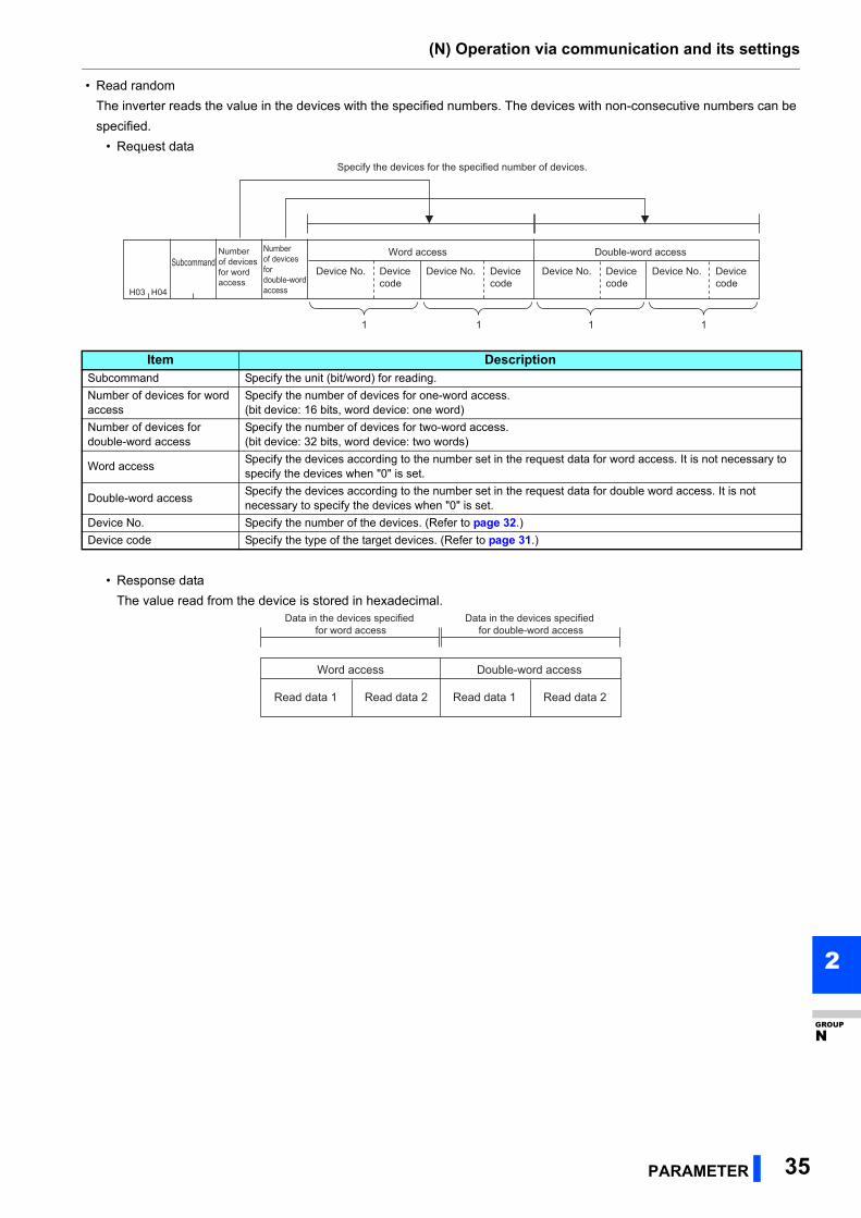
• Read random
The inverter reads the value in the devices with the specified numbers. The devices with non-consecutive numbers can be
specified.
• Request data
• Response data
The value read from the device is stored in hexadecimal.
Item DescriptionSubcommand Specify the unit (bit/word) for reading.
Number of devices for word access
Specify the number of devices for one-word access.(bit device: 16 bits, word device: one word)
Number of devices for double-word access
Specify the number of devices for two-word access.(bit device: 32 bits, word device: two words)
Word accessSpecify the devices according to the number set in the request data for word access. It is not necessary to specify the devices when "0" is set.
Double-word accessSpecify the devices according to the number set in the request data for double word access. It is not necessary to specify the devices when "0" is set.
Device No. Specify the number of the devices. (Refer to page 32.)
Device code Specify the type of the target devices. (Refer to page 31.)
H03 H04
Specify the devices for the specified number of devices.
Number of devices for word access
SubcommandDevice No. Device No. Device No. Device No.
Word access Double-word accessNumber of devices for double-word access
Device code
Device code
Device code
Device code
1 1 1 1
Word access
Data in the devices specified for word access
Data in the devices specified for double-word access
Read data 1 Read data 2
Double-word access
Read data 1 Read data 2
(N) Operation via communication and its settings
36 PARAMETER
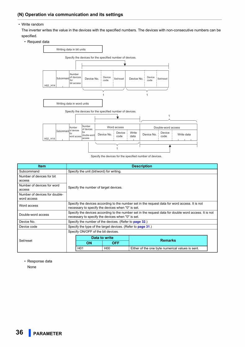
• Write random
The inverter writes the value in the devices with the specified numbers. The devices with non-consecutive numbers can be
specified.
• Request data
• Response data
None
Item DescriptionSubcommand Specify the unit (bit/word) for writing.
Number of devices for bit access
Specify the number of target devices.Number of devices for word access
Number of devices for double-word access
Word accessSpecify the devices according to the number set in the request data for word access. It is not necessary to specify the devices when "0" is set.
Double-word accessSpecify the devices according to the number set in the request data for double word access. It is not necessary to specify the devices when "0" is set.
Device No. Specify the number of the devices. (Refer to page 32.)
Device code Specify the type of the target devices. (Refer to page 31.)
Set/reset
Specify ON/OFF of the bit devices.
H02 H14
H02 H14
Double-word access
Device No. Device code Write data
Specify the devices for the specified number of devices.
Specify the devices for the specified number of devices.
Specify the devices for the specified number of devices.
Writing data in bit units
Writing data in word units
Number of devices for bit access
Device No.Subcommand
Subcommand
Device code Set/reset Device No. Device
code Set/reset
Number of devices for word access
Device No.
Word accessNumber of devices for double-word access
Device code
Write data
1
1
1 1
Data to writeRemarks
ON OFFH01 H00 Either of the one byte numerical values is sent.
(N) Operation via communication and its settings
PARAMETER 37
2
GROUP
N
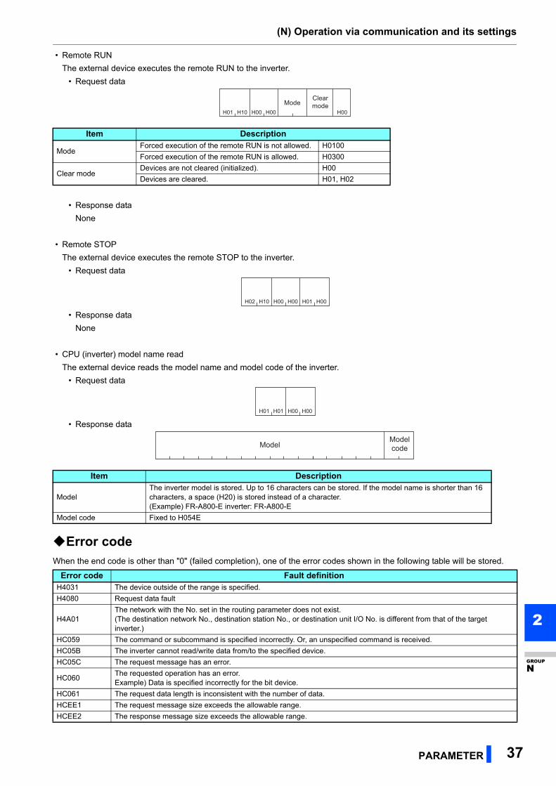
• Remote RUN
The external device executes the remote RUN to the inverter.
• Request data
• Response data
None
• Remote STOP
The external device executes the remote STOP to the inverter.
• Request data
• Response data
None
• CPU (inverter) model name read
The external device reads the model name and model code of the inverter.
• Request data
• Response data
Error codeWhen the end code is other than "0" (failed completion), one of the error codes shown in the following table will be stored.
Item Description
ModeForced execution of the remote RUN is not allowed. H0100
Forced execution of the remote RUN is allowed. H0300
Clear modeDevices are not cleared (initialized). H00
Devices are cleared. H01, H02
Item Description
ModelThe inverter model is stored. Up to 16 characters can be stored. If the model name is shorter than 16 characters, a space (H20) is stored instead of a character.(Example) FR-A800-E inverter: FR-A800-E
Model code Fixed to H054E
Error code Fault definitionH4031 The device outside of the range is specified.
H4080 Request data fault
H4A01The network with the No. set in the routing parameter does not exist.(The destination network No., destination station No., or destination unit I/O No. is different from that of the target inverter.)
HC059 The command or subcommand is specified incorrectly. Or, an unspecified command is received.
HC05B The inverter cannot read/write data from/to the specified device.
HC05C The request message has an error.
HC060The requested operation has an error.Example) Data is specified incorrectly for the bit device.
HC061 The request data length is inconsistent with the number of data.
HCEE1 The request message size exceeds the allowable range.
HCEE2 The response message size exceeds the allowable range.
H01 H10 H00 H00 H00Mode
Clearmode
H02 H10 H00 H00 H01 H00
H01 H01 H00 H00
ModelModelcode
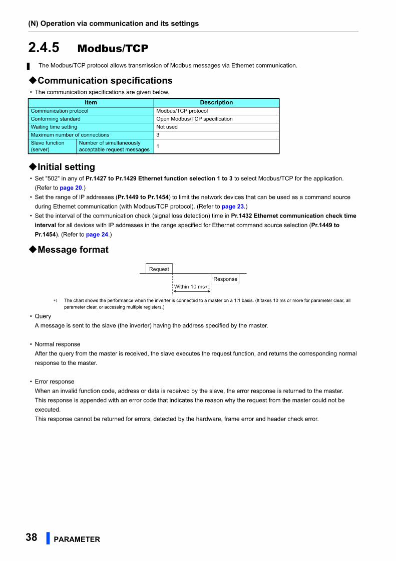
(N) Operation via communication and its settings
38 PARAMETER
2.4.5 Modbus/TCP
Communication specifications • The communication specifications are given below.
Initial setting • Set "502" in any of Pr.1427 to Pr.1429 Ethernet function selection 1 to 3 to select Modbus/TCP for the application.
(Refer to page 20.)
• Set the range of IP addresses (Pr.1449 to Pr.1454) to limit the network devices that can be used as a command source
during Ethernet communication (with Modbus/TCP protocol). (Refer to page 23.)
• Set the interval of the communication check (signal loss detection) time in Pr.1432 Ethernet communication check time
interval for all devices with IP addresses in the range specified for Ethernet command source selection (Pr.1449 to
Pr.1454). (Refer to page 24.)
Message format
The chart shows the performance when the inverter is connected to a master on a 1:1 basis. (It takes 10 ms or more for parameter clear, all
parameter clear, or accessing multiple registers.)
• Query
A message is sent to the slave (the inverter) having the address specified by the master.
• Normal response
After the query from the master is received, the slave executes the request function, and returns the corresponding normal
response to the master.
• Error response
When an invalid function code, address or data is received by the slave, the error response is returned to the master.
This response is appended with an error code that indicates the reason why the request from the master could not be
executed.
This response cannot be returned for errors, detected by the hardware, frame error and header check error.
The Modbus/TCP protocol allows transmission of Modbus messages via Ethernet communication.
Item DescriptionCommunication protocol Modbus/TCP protocol
Conforming standard Open Modbus/TCP specification
Waiting time setting Not used
Maximum number of connections 3
Slave function(server)
Number of simultaneously acceptable request messages
1
Request
ResponseWithin 10 ms∗1
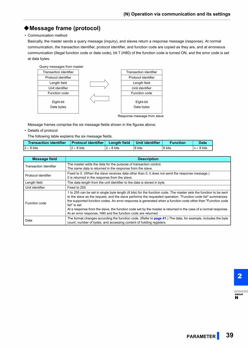
(N) Operation via communication and its settings
PARAMETER 39
2
GROUP
N
Message frame (protocol) • Communication method
Basically, the master sends a query message (inquiry), and slaves return a response message (response). At normal
communication, the transaction identifier, protocol identifier, and function code are copied as they are, and at erroneous
communication (illegal function code or data code), bit 7 (H80) of the function code is turned ON, and the error code is set
at data bytes.
Message frames comprise the six message fields shown in the figures above.
• Details of protocol
The following table explains the six message fields.
Query messages from master
Transaction identifier Transaction identifier
Protocol identifier Protocol identifier
Length field Length field
Unit identifier Unit identifier
Function code Function code
Eight-bit
Data bytes
Eight-bit
Data bytes
Response message from slave
Transaction identifier Protocol identifier Length field Unit identifier Function Data2 8 bits 2 8 bits 2 8 bits 8 bits 8 bits n 8 bits
Message field Description
Transaction identifierThe master adds the data for the purpose of transaction control.The same data is returned in the response from the slave.
Protocol identifierFixed to 0. (When the slave receives data other than 0, it does not send the response message.)0 is returned in the response from the slave.
Length field The data length from the unit identifier to the data is stored in byte.
Unit identifier Fixed to 255
Function code
1 to 255 can be set in single byte length (8 bits) for the function code. The master sets the function to be sent to the slave as the request, and the slave performs the requested operation. "Function code list" summarizes the supported function codes. An error response is generated when a function code other than "Function code list" is set.At a response from the slave, the function code set by the master is returned in the case of a normal response. At an error response, H80 and the function code are returned.
DataThe format changes according the function code. (Refer to page 41.) The data, for example, includes the byte count, number of bytes, and accessing content of holding registers.
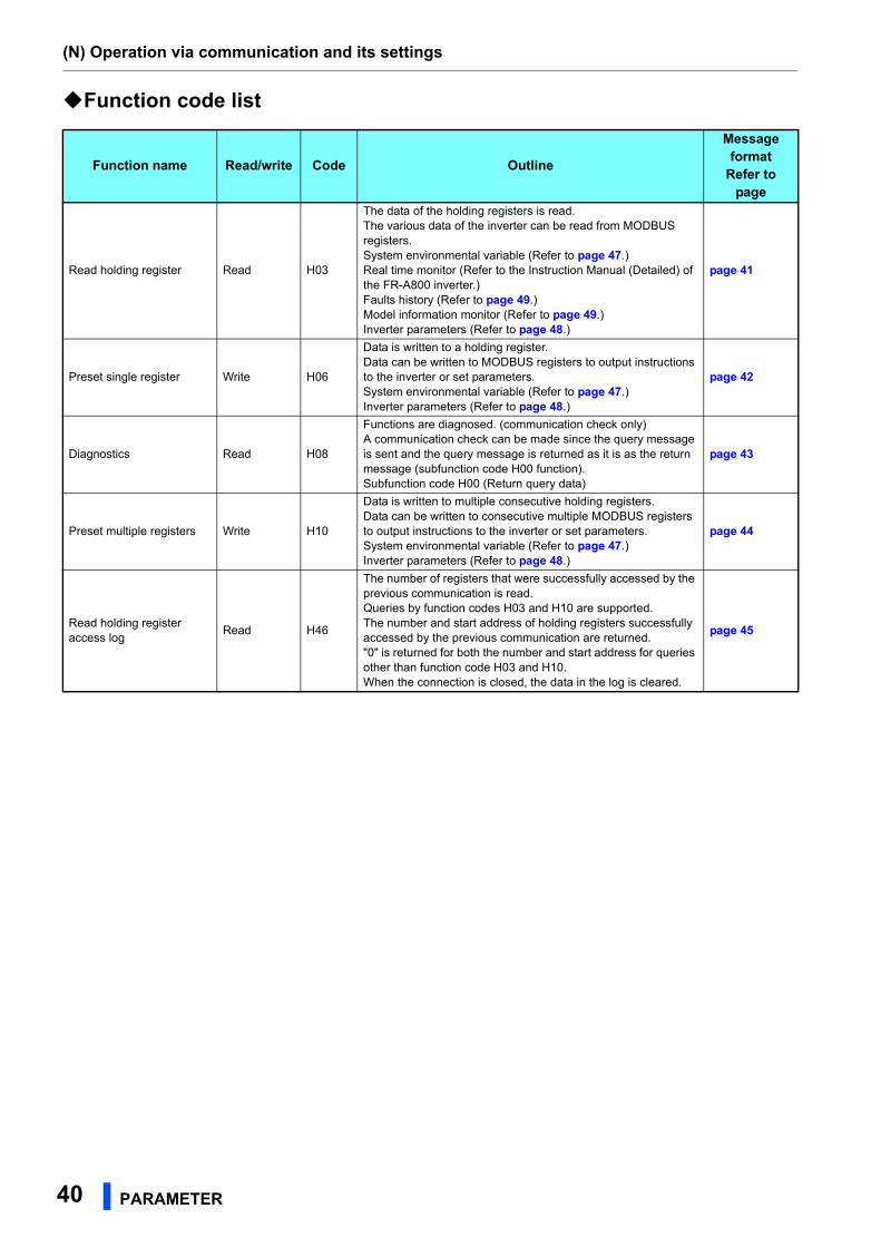
(N) Operation via communication and its settings
40 PARAMETER
Function code list
Function name Read/write Code Outline
Message format
Refer to page
Read holding register Read H03
The data of the holding registers is read.The various data of the inverter can be read from MODBUS registers.System environmental variable (Refer to page 47.)Real time monitor (Refer to the Instruction Manual (Detailed) of the FR-A800 inverter.)Faults history (Refer to page 49.)Model information monitor (Refer to page 49.)Inverter parameters (Refer to page 48.)
page 41
Preset single register Write H06
Data is written to a holding register.Data can be written to MODBUS registers to output instructions to the inverter or set parameters.System environmental variable (Refer to page 47.)Inverter parameters (Refer to page 48.)
page 42
Diagnostics Read H08
Functions are diagnosed. (communication check only)A communication check can be made since the query message is sent and the query message is returned as it is as the return message (subfunction code H00 function).Subfunction code H00 (Return query data)
page 43
Preset multiple registers Write H10
Data is written to multiple consecutive holding registers.Data can be written to consecutive multiple MODBUS registers to output instructions to the inverter or set parameters.System environmental variable (Refer to page 47.)Inverter parameters (Refer to page 48.)
page 44
Read holding register access log
Read H46
The number of registers that were successfully accessed by the previous communication is read.Queries by function codes H03 and H10 are supported.The number and start address of holding registers successfully accessed by the previous communication are returned."0" is returned for both the number and start address for queries other than function code H03 and H10.When the connection is closed, the data in the log is cleared.
page 45
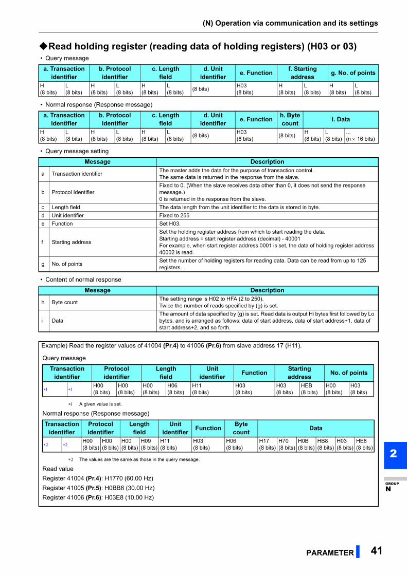
(N) Operation via communication and its settings
PARAMETER 41
2
GROUP
N
Read holding register (reading data of holding registers) (H03 or 03) • Query message
• Normal response (Response message)
• Query message setting
• Content of normal response
a. Transactionidentifier
b. Protocolidentifier
c. Lengthfield
d. Unitidentifier
e. Functionf. Starting address
g. No. of points
H(8 bits)
L(8 bits)
H(8 bits)
L(8 bits)
H(8 bits)
L(8 bits)
(8 bits)H03(8 bits)
H(8 bits)
L(8 bits)
H(8 bits)
L(8 bits)
a. Transactionidentifier
b. Protocolidentifier
c. Lengthfield
d. Unitidentifier
e. Functionh. Byte count
i. Data
H(8 bits)
L(8 bits)
H(8 bits)
L(8 bits)
H(8 bits)
L(8 bits)
(8 bits)H03(8 bits)
(8 bits)H(8 bits)
L(8 bits)
...(n 16 bits)
Message Description
a Transaction identifierThe master adds the data for the purpose of transaction control.The same data is returned in the response from the slave.
b Protocol IdentifierFixed to 0. (When the slave receives data other than 0, it does not send the response message.)0 is returned in the response from the slave.
c Length field The data length from the unit identifier to the data is stored in byte.
d Unit identifier Fixed to 255
e Function Set H03.
f Starting address
Set the holding register address from which to start reading the data.Starting address = start register address (decimal) - 40001For example, when start register address 0001 is set, the data of holding register address 40002 is read.
g No. of pointsSet the number of holding registers for reading data. Data can be read from up to 125 registers.
Message Description
h Byte countThe setting range is H02 to HFA (2 to 250).Twice the number of reads specified by (g) is set.
i DataThe amount of data specified by (g) is set. Read data is output Hi bytes first followed by Lo bytes, and is arranged as follows: data of start address, data of start address+1, data of start address+2, and so forth.
Example) Read the register values of 41004 (Pr.4) to 41006 (Pr.6) from slave address 17 (H11).
Query message
A given value is set.
Normal response (Response message)
The values are the same as those in the query message.
Read value
Register 41004 (Pr.4): H1770 (60.00 Hz)
Register 41005 (Pr.5): H0BB8 (30.00 Hz)
Register 41006 (Pr.6): H03E8 (10.00 Hz)
Transactionidentifier
Protocolidentifier
Lengthfield
Unitidentifier
FunctionStarting address
No. of points
H00(8 bits)
H00(8 bits)
H00(8 bits)
H06(8 bits)
H11(8 bits)
H03(8 bits)
H03(8 bits)
HEB(8 bits)
H00(8 bits)
H03(8 bits)
Transactionidentifier
Protocolidentifier
Lengthfield
Unitidentifier
FunctionByte count
Data
H00(8 bits)
H00(8 bits)
H00(8 bits)
H09(8 bits)
H11(8 bits)
H03(8 bits)
H06(8 bits)
H17(8 bits)
H70(8 bits)
H0B(8 bits)
HB8(8 bits)
H03(8 bits)
HE8(8 bits)
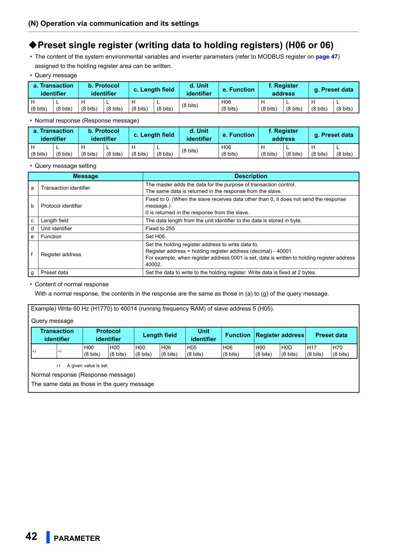
(N) Operation via communication and its settings
42 PARAMETER
Preset single register (writing data to holding registers) (H06 or 06) • The content of the system environmental variables and inverter parameters (refer to MODBUS register on page 47)
assigned to the holding register area can be written.
• Query message
• Normal response (Response message)
• Query message setting
• Content of normal response
With a normal response, the contents in the response are the same as those in (a) to (g) of the query message.
a. Transactionidentifier
b. Protocolidentifier
c. Length fieldd. Unit
identifiere. Function
f. Register address
g. Preset data
H(8 bits)
L(8 bits)
H(8 bits)
L(8 bits)
H(8 bits)
L(8 bits)
(8 bits)H06(8 bits)
H(8 bits)
L(8 bits)
H(8 bits)
L(8 bits)
a. Transactionidentifier
b. Protocolidentifier
c. Length fieldd. Unit
identifiere. Function
f. Register address
g. Preset data
H(8 bits)
L(8 bits)
H(8 bits)
L(8 bits)
H(8 bits)
L(8 bits)
(8 bits)H06(8 bits)
H(8 bits)
L(8 bits)
H(8 bits)
L(8 bits)
Message Description
a Transaction identifierThe master adds the data for the purpose of transaction control.The same data is returned in the response from the slave.
b Protocol identifierFixed to 0. (When the slave receives data other than 0, it does not send the response message.)0 is returned in the response from the slave.
c Length field The data length from the unit identifier to the data is stored in byte.
d Unit identifier Fixed to 255
e Function Set H06.
f Register address
Set the holding register address to write data to.Register address = holding register address (decimal) - 40001For example, when register address 0001 is set, data is written to holding register address 40002.
g Preset data Set the data to write to the holding register. Write data is fixed at 2 bytes.
Example) Write 60 Hz (H1770) to 40014 (running frequency RAM) of slave address 5 (H05).
Query message
A given value is set.
Normal response (Response message)
The same data as those in the query message
Transactionidentifier
Protocolidentifier
Length fieldUnit
identifierFunction Register address Preset data
H00(8 bits)
H00(8 bits)
H00(8 bits)
H06(8 bits)
H05(8 bits)
H06(8 bits)
H00(8 bits)
H0D(8 bits)
H17(8 bits)
H70(8 bits)
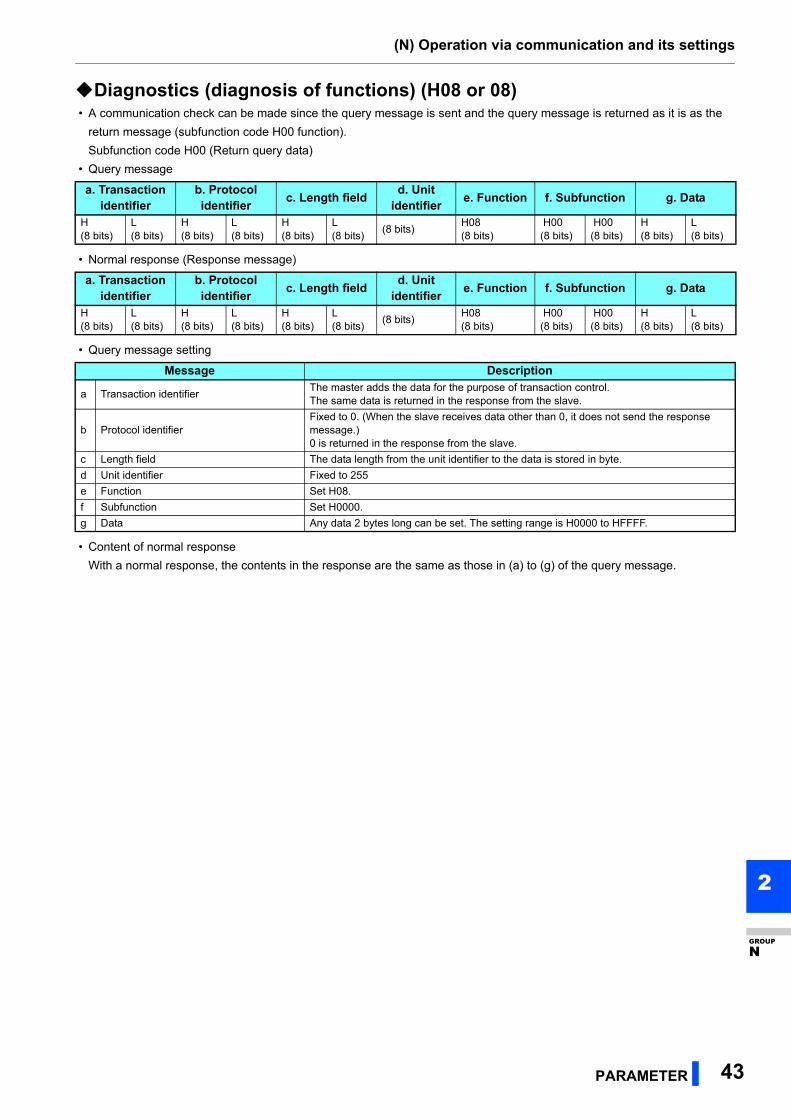
(N) Operation via communication and its settings
PARAMETER 43
2
GROUP
N
Diagnostics (diagnosis of functions) (H08 or 08) • A communication check can be made since the query message is sent and the query message is returned as it is as the
return message (subfunction code H00 function).
Subfunction code H00 (Return query data)
• Query message
• Normal response (Response message)
• Query message setting
• Content of normal response
With a normal response, the contents in the response are the same as those in (a) to (g) of the query message.
a. Transactionidentifier
b. Protocolidentifier
c. Length fieldd. Unit
identifiere. Function f. Subfunction g. Data
H(8 bits)
L(8 bits)
H(8 bits)
L(8 bits)
H(8 bits)
L(8 bits)
(8 bits)H08(8 bits)
H00(8 bits)
H00(8 bits)
H(8 bits)
L(8 bits)
a. Transactionidentifier
b. Protocolidentifier
c. Length fieldd. Unit
identifiere. Function f. Subfunction g. Data
H(8 bits)
L(8 bits)
H(8 bits)
L(8 bits)
H(8 bits)
L(8 bits)
(8 bits)H08(8 bits)
H00(8 bits)
H00(8 bits)
H(8 bits)
L(8 bits)
Message Description
a Transaction identifierThe master adds the data for the purpose of transaction control.The same data is returned in the response from the slave.
b Protocol identifierFixed to 0. (When the slave receives data other than 0, it does not send the response message.)0 is returned in the response from the slave.
c Length field The data length from the unit identifier to the data is stored in byte.
d Unit identifier Fixed to 255
e Function Set H08.
f Subfunction Set H0000.
g Data Any data 2 bytes long can be set. The setting range is H0000 to HFFFF.
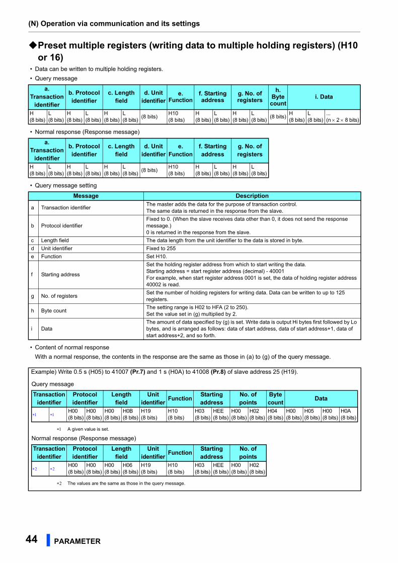
(N) Operation via communication and its settings
44 PARAMETER
Preset multiple registers (writing data to multiple holding registers) (H10 or 16)
• Data can be written to multiple holding registers.
• Query message
• Normal response (Response message)
• Query message setting
• Content of normal response
With a normal response, the contents in the response are the same as those in (a) to (g) of the query message.
a. Transaction
identifier
b. Protocolidentifier
c. Length field
d. Unitidentifier
e. Function
f. Starting address
g. No. of registers
h. Byte count
i. Data
H(8 bits)
L(8 bits)
H(8 bits)
L(8 bits)
H(8 bits)
L(8 bits)
(8 bits)H10(8 bits)
H(8 bits)
L(8 bits)
H(8 bits)
L(8 bits)
(8 bits)H(8 bits)
L(8 bits)
...(n 2 8 bits)
a. Transaction
identifier
b. Protocolidentifier
c. Length field
d. Unitidentifier
e. Function
f. Starting address
g. No. of registers
H(8 bits)
L(8 bits)
H(8 bits)
L(8 bits)
H(8 bits)
L(8 bits)
(8 bits)H10(8 bits)
H(8 bits)
L(8 bits)
H(8 bits)
L(8 bits)
Message Description
a Transaction identifierThe master adds the data for the purpose of transaction control.The same data is returned in the response from the slave.
b Protocol identifierFixed to 0. (When the slave receives data other than 0, it does not send the response message.)0 is returned in the response from the slave.
c Length field The data length from the unit identifier to the data is stored in byte.
d Unit identifier Fixed to 255
e Function Set H10.
f Starting address
Set the holding register address from which to start writing the data.Starting address = start register address (decimal) - 40001For example, when start register address 0001 is set, the data of holding register address 40002 is read.
g No. of registersSet the number of holding registers for writing data. Data can be written to up to 125 registers.
h Byte countThe setting range is H02 to HFA (2 to 250).Set the value set in (g) multiplied by 2.
i DataThe amount of data specified by (g) is set. Write data is output Hi bytes first followed by Lo bytes, and is arranged as follows: data of start address, data of start address+1, data of start address+2, and so forth.
Example) Write 0.5 s (H05) to 41007 (Pr.7) and 1 s (H0A) to 41008 (Pr.8) of slave address 25 (H19).
Query message
A given value is set.
Normal response (Response message)
The values are the same as those in the query message.
Transactionidentifier
Protocolidentifier
Length field
Unitidentifier
FunctionStarting address
No. of points
Byte count
Data
H00(8 bits)
H00(8 bits)
H00(8 bits)
H0B(8 bits)
H19(8 bits)
H10(8 bits)
H03(8 bits)
HEE(8 bits)
H00(8 bits)
H02(8 bits)
H04(8 bits)
H00(8 bits)
H05(8 bits)
H00(8 bits)
H0A(8 bits)
Transactionidentifier
Protocolidentifier
Length field
Unitidentifier
FunctionStarting address
No. of points
H00(8 bits)
H00(8 bits)
H00(8 bits)
H06(8 bits)
H19(8 bits)
H10(8 bits)
H03(8 bits)
HEE(8 bits)
H00(8 bits)
H02(8 bits)
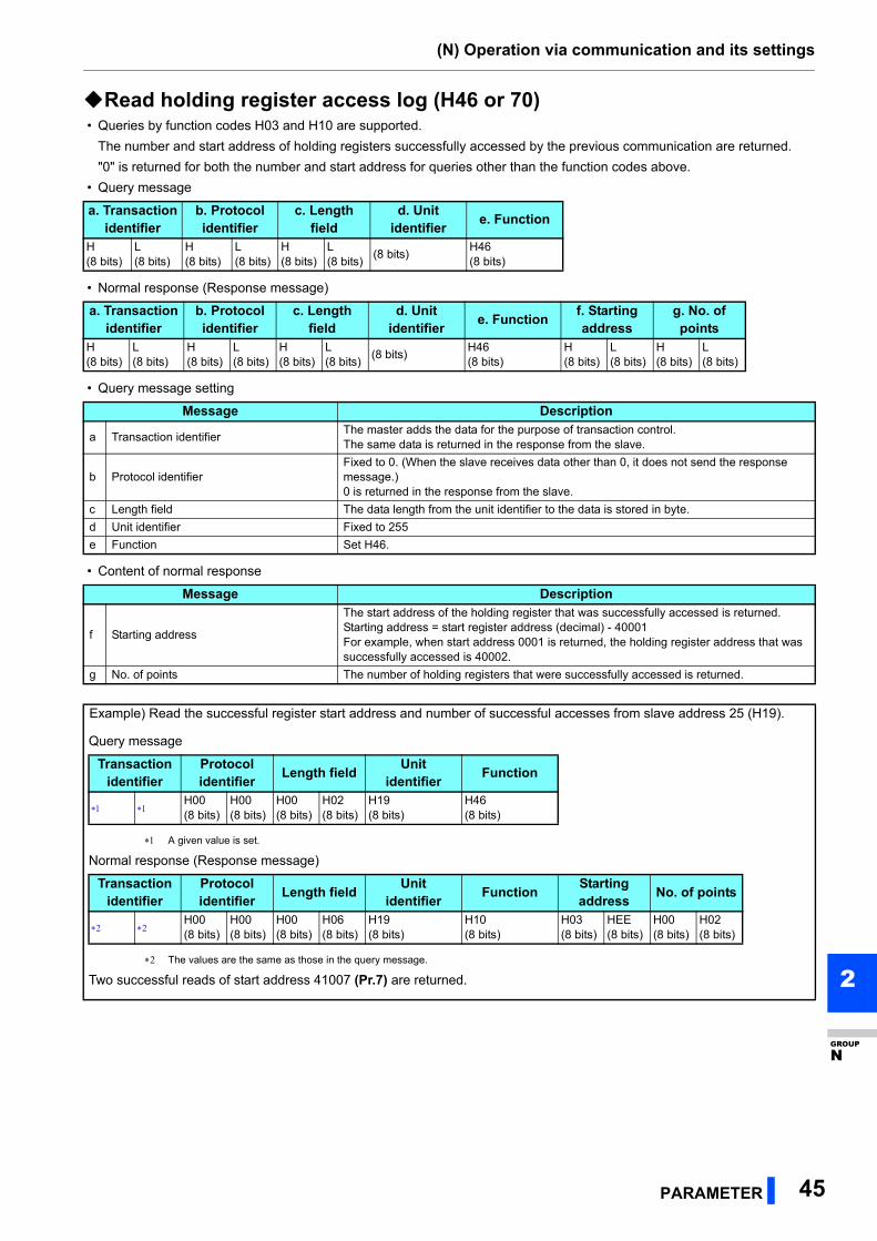
(N) Operation via communication and its settings
PARAMETER 45
2
GROUP
N
Read holding register access log (H46 or 70) • Queries by function codes H03 and H10 are supported.
The number and start address of holding registers successfully accessed by the previous communication are returned.
"0" is returned for both the number and start address for queries other than the function codes above.
• Query message
• Normal response (Response message)
• Query message setting
• Content of normal response
a. Transactionidentifier
b. Protocolidentifier
c. Length field
d. Unitidentifier
e. Function
H(8 bits)
L(8 bits)
H(8 bits)
L(8 bits)
H(8 bits)
L (8 bits)
(8 bits)H46(8 bits)
a. Transactionidentifier
b. Protocolidentifier
c. Length field
d. Unitidentifier
e. Functionf. Starting address
g. No. of points
H(8 bits)
L(8 bits)
H(8 bits)
L(8 bits)
H(8 bits)
L(8 bits)
(8 bits)H46(8 bits)
H(8 bits)
L(8 bits)
H(8 bits)
L(8 bits)
Message Description
a Transaction identifierThe master adds the data for the purpose of transaction control.The same data is returned in the response from the slave.
b Protocol identifierFixed to 0. (When the slave receives data other than 0, it does not send the response message.)0 is returned in the response from the slave.
c Length field The data length from the unit identifier to the data is stored in byte.
d Unit identifier Fixed to 255
e Function Set H46.
Message Description
f Starting address
The start address of the holding register that was successfully accessed is returned.Starting address = start register address (decimal) - 40001For example, when start address 0001 is returned, the holding register address that was successfully accessed is 40002.
g No. of points The number of holding registers that were successfully accessed is returned.
Example) Read the successful register start address and number of successful accesses from slave address 25 (H19).
Query message
A given value is set.
Normal response (Response message)
The values are the same as those in the query message.
Two successful reads of start address 41007 (Pr.7) are returned.
Transactionidentifier
Protocolidentifier
Length fieldUnit
identifierFunction
H00(8 bits)
H00(8 bits)
H00(8 bits)
H02(8 bits)
H19(8 bits)
H46(8 bits)
Transactionidentifier
Protocolidentifier
Length fieldUnit
identifierFunction
Starting address
No. of points
H00(8 bits)
H00(8 bits)
H00(8 bits)
H06(8 bits)
H19(8 bits)
H10(8 bits)
H03(8 bits)
HEE(8 bits)
H00(8 bits)
H02(8 bits)
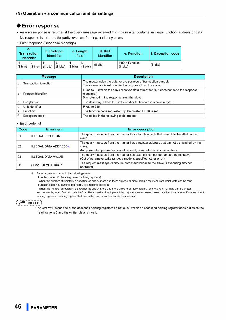
(N) Operation via communication and its settings
46 PARAMETER
Error response • An error response is returned if the query message received from the master contains an illegal function, address or data.
No response is returned for parity, overrun, framing, and busy errors.
• Error response (Response message)
• Error code list
An error does not occur in the following cases:
Function code H03 (reading data of holding registers)
When the number of registers is specified as one or more and there are one or more holding registers from which data can be read
Function code H10 (writing data to multiple holding registers)
When the number of registers is specified as one or more and there are one or more holding registers to which data can be written
In other words, when function code H03 or H10 is used and multiple holding registers are accessed, an error will not occur even if a nonexistent
holding register or holding register that cannot be read or written from/to is accessed.
NOTE • An error will occur if all of the accessed holding registers do not exist. When an accessed holding register does not exist, the
read value is 0 and the written data is invalid.
a. Transaction
identifier
b. Protocolidentifier
c. Length field
d. Unitidentifier
e. Function f. Exception code
H(8 bits)
L(8 bits)
H(8 bits)
L(8 bits)
H(8 bits)
L(8 bits)
(8 bits)H80 + Function(8 bits)
(8 bits)
Message Description
a Transaction identifierThe master adds the data for the purpose of transaction control.The same data is returned in the response from the slave.
b Protocol identifierFixed to 0. (When the slave receives data other than 0, it does not send the response message.)0 is returned in the response from the slave.
c Length field The data length from the unit identifier to the data is stored in byte.
d Unit identifier Fixed to 255
e Function The function code requested by the master + H80 is set.
f Exception code The codes in the following table are set.
Code Error item Error description
01 ILLEGAL FUNCTIONThe query message from the master has a function code that cannot be handled by the slave.
02 ILLEGAL DATA ADDRESS
The query message from the master has a register address that cannot be handled by the slave.(No parameter, parameter cannot be read, parameter cannot be written)
03 ILLEGAL DATA VALUEThe query message from the master has data that cannot be handled by the slave.(Out of parameter write range, a mode is specified, other error)
06 SLAVE DEVICE BUSYThe request message cannot be processed because the slave is executing another operation.
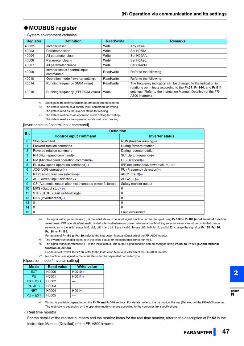
(N) Operation via communication and its settings
PARAMETER 47
2
GROUP
N
MODBUS register • System environment variables
Settings in the communication parameters are not cleared.
The data is written as a control input command for writing.
The data is read as the inverter status for reading.
The data is written as an operation mode setting for writing.
The data is read as the operation mode status for reading.
[Inverter status / control input command]
The signal within parentheses ( ) is the initial status. The input signal function can be changed using Pr.180 to Pr.189 (input terminal function
selection). JOG operation/automatic restart after instantaneous power failure/start self-holding selection/reset cannot be controlled over a
network, so in the initial status bit6, bit9, bit11, and bit12 are invalid. To use bit6, bit9, bit11, and bit12, change the signal by Pr.185, Pr.186,
Pr.188, or Pr.189.
For details of Pr.180 to Pr.189, refer to the Instruction Manual (Detailed) of the FR-A800 inverter.
The inverter run enable signal is in the initial status for the separated converter type.
The signal within parentheses ( ) is the initial status. The output signal function can be changed using Pr.190 to Pr.196 (output terminal
function selection).
For details of Pr.190 to Pr.196, refer to the Instruction Manual (Detailed) of the FR-A800 inverter.
No function is assigned in the initial status for the separated converter type.
[Operation mode / inverter setting]
Writing is available depending on the Pr.79 and Pr.340 settings. For details, refer to the Instruction Manual (Detailed) of the FR-A800 inverter.
The restrictions depending on the operation mode changes according to the computer link specifications.
• Real time monitor
For the details of the register numbers and the monitor items for the real time monitor, refer to the description of Pr.52 in the
Instruction Manual (Detailed) of the FR-A800 inverter.
Register Definition Read/write Remarks40002 Inverter reset Write Any value
40003 Parameter clear Write Set H965A.
40004 All parameter clear Write Set H99AA.
40006 Parameter clear Write Set H5A96.
40007 All parameter clear Write Set HAA99.
40009Inverter status / control input command
Read/write Refer to the following.
40010 Operation mode / inverter setting Read/write Refer to the following.
40014 Running frequency (RAM value) Read/write The frequency indication can be changed to the indication in rotations per minute according to the Pr.37, Pr.144, and Pr.811 settings. (Refer to the Instruction Manual (Detailed) of the FR-A800 inverter.)
40015 Running frequency (EEPROM value) Write
BitDefinition
Control input command Inverter status0 Stop command RUN (Inverter running)
1 Forward rotation command During forward rotation
2 Reverse rotation command During reverse rotation
3 RH (High-speed command) SU (Up to frequency)
4 RM (Middle-speed operation command) OL (Overload)
5 RL (Low-speed operation command) IPF (Instantaneous power failure)
6 JOG (JOG operation) FU (Frequency detection)
7 RT (Second function selection) ABC1 (Fault)
8 AU (Current input selection) ABC2 (—)
9 CS (Automatic restart after instantaneous power failure) Safety monitor output
10 MRS (Output stop) 0
11 STP (STOP) (Start self-holding) 0
12 RES (Inverter reset) 0
13 0 0
14 0 0
15 0 Fault occurrence
Mode Read value Write valueEXT H0000 H0010
PU H0001 H0011
EXT JOG H0002 —
PU JOG H0003 —
NET H0004 H0014
PU + EXT H0005 —
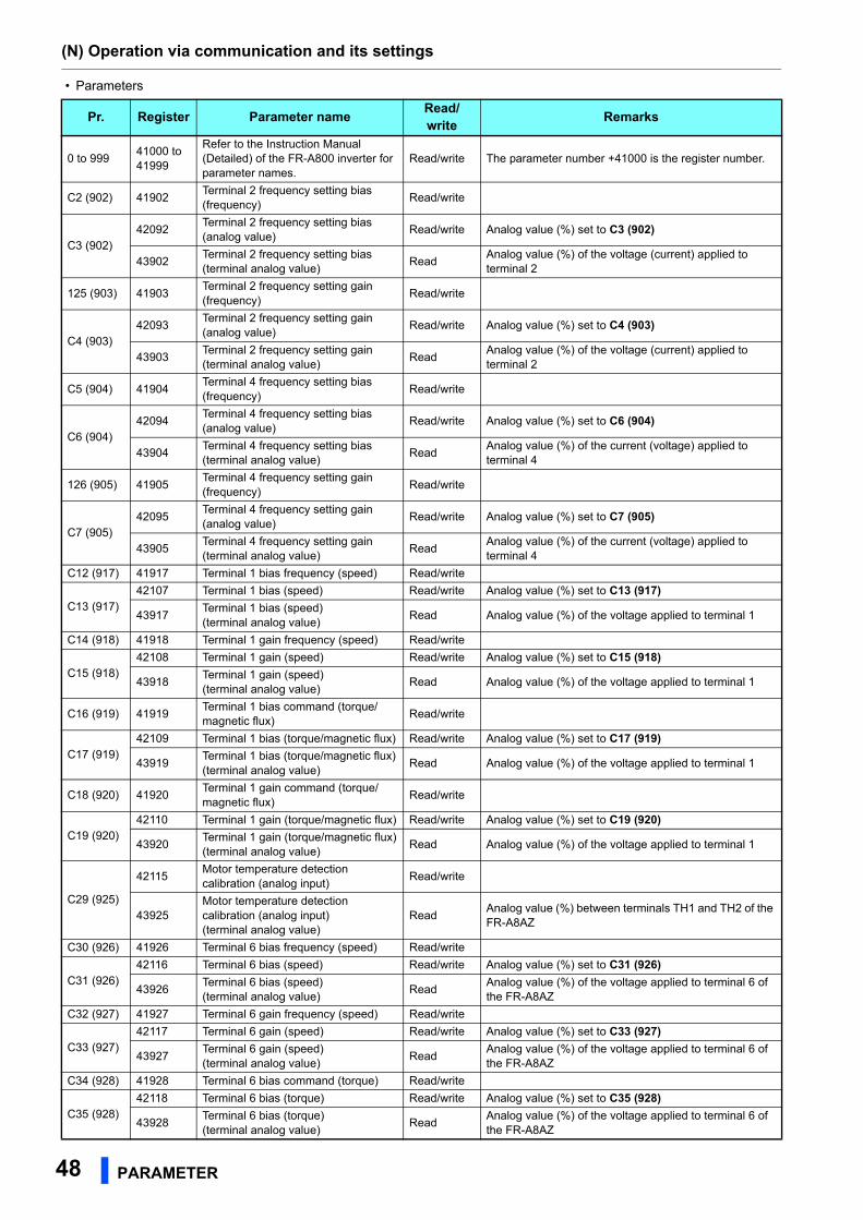
(N) Operation via communication and its settings
48 PARAMETER
• Parameters
Pr. Register Parameter nameRead/write
Remarks
0 to 99941000 to 41999
Refer to the Instruction Manual (Detailed) of the FR-A800 inverter for parameter names.
Read/write The parameter number +41000 is the register number.
C2 (902) 41902Terminal 2 frequency setting bias(frequency)
Read/write
C3 (902)42092
Terminal 2 frequency setting bias(analog value)
Read/write Analog value (%) set to C3 (902)
43902Terminal 2 frequency setting bias(terminal analog value)
ReadAnalog value (%) of the voltage (current) applied to terminal 2
125 (903) 41903Terminal 2 frequency setting gain(frequency)
Read/write
C4 (903)42093
Terminal 2 frequency setting gain(analog value)
Read/write Analog value (%) set to C4 (903)
43903Terminal 2 frequency setting gain(terminal analog value)
ReadAnalog value (%) of the voltage (current) applied to terminal 2
C5 (904) 41904Terminal 4 frequency setting bias(frequency)
Read/write
C6 (904)42094
Terminal 4 frequency setting bias(analog value)
Read/write Analog value (%) set to C6 (904)
43904Terminal 4 frequency setting bias(terminal analog value)
ReadAnalog value (%) of the current (voltage) applied to terminal 4
126 (905) 41905Terminal 4 frequency setting gain(frequency)
Read/write
C7 (905)42095
Terminal 4 frequency setting gain(analog value)
Read/write Analog value (%) set to C7 (905)
43905Terminal 4 frequency setting gain(terminal analog value)
ReadAnalog value (%) of the current (voltage) applied to terminal 4
C12 (917) 41917 Terminal 1 bias frequency (speed) Read/write
C13 (917)42107 Terminal 1 bias (speed) Read/write Analog value (%) set to C13 (917)
43917Terminal 1 bias (speed)(terminal analog value)
Read Analog value (%) of the voltage applied to terminal 1
C14 (918) 41918 Terminal 1 gain frequency (speed) Read/write
C15 (918)42108 Terminal 1 gain (speed) Read/write Analog value (%) set to C15 (918)
43918Terminal 1 gain (speed)(terminal analog value)
Read Analog value (%) of the voltage applied to terminal 1
C16 (919) 41919Terminal 1 bias command (torque/magnetic flux)
Read/write
C17 (919)42109 Terminal 1 bias (torque/magnetic flux) Read/write Analog value (%) set to C17 (919)
43919Terminal 1 bias (torque/magnetic flux)(terminal analog value)
Read Analog value (%) of the voltage applied to terminal 1
C18 (920) 41920Terminal 1 gain command (torque/magnetic flux)
Read/write
C19 (920)42110 Terminal 1 gain (torque/magnetic flux) Read/write Analog value (%) set to C19 (920)
43920Terminal 1 gain (torque/magnetic flux)(terminal analog value)
Read Analog value (%) of the voltage applied to terminal 1
C29 (925)
42115Motor temperature detection calibration (analog input)
Read/write
43925Motor temperature detection calibration (analog input)(terminal analog value)
ReadAnalog value (%) between terminals TH1 and TH2 of the FR-A8AZ
C30 (926) 41926 Terminal 6 bias frequency (speed) Read/write
C31 (926)42116 Terminal 6 bias (speed) Read/write Analog value (%) set to C31 (926)
43926Terminal 6 bias (speed)(terminal analog value)
ReadAnalog value (%) of the voltage applied to terminal 6 of the FR-A8AZ
C32 (927) 41927 Terminal 6 gain frequency (speed) Read/write
C33 (927)42117 Terminal 6 gain (speed) Read/write Analog value (%) set to C33 (927)
43927Terminal 6 gain (speed)(terminal analog value)
ReadAnalog value (%) of the voltage applied to terminal 6 of the FR-A8AZ
C34 (928) 41928 Terminal 6 bias command (torque) Read/write
C35 (928)42118 Terminal 6 bias (torque) Read/write Analog value (%) set to C35 (928)
43928Terminal 6 bias (torque)(terminal analog value)
ReadAnalog value (%) of the voltage applied to terminal 6 of the FR-A8AZ
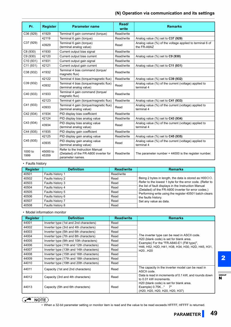
(N) Operation via communication and its settings
PARAMETER 49
2
GROUP
N
• Faults history
• Model information monitor
NOTE • When a 32-bit parameter setting or monitor item is read and the value to be read exceeds HFFFF, HFFFF is returned.
C36 (929) 41929 Terminal 6 gain command (torque) Read/write
C37 (929)42119 Terminal 6 gain (torque) Read/write Analog value (%) set to C37 (929)
43929Terminal 6 gain (torque)(terminal analog value)
ReadAnalog value (%) of the voltage applied to terminal 6 of the FR-A8AZ
C8 (930) 41930 Current output bias signal Read/write
C9 (930) 42120 Current output bias current Read/write Analog value (%) set to C9 (930)
C10 (931) 41931 Current output gain signal Read/write
C11 (931) 42121 Current output gain current Read/write Analog value (%) set to C11 (931)
C38 (932) 41932Terminal 4 bias command (torque/magnetic flux)
Read/write
C39 (932)42122 Terminal 4 bias (torque/magnetic flux) Read/write Analog value (%) set to C39 (932)
43932Terminal 4 bias (torque/magnetic flux)(terminal analog value)
ReadAnalog value (%) of the current (voltage) applied to terminal 4
C40 (933) 41933Terminal 4 gain command (torque/magnetic flux)
Read/write
C41 (933)42123 Terminal 4 gain (torque/magnetic flux) Read/write Analog value (%) set to C41 (933)
43933Terminal 4 gain (torque/magnetic flux)(terminal analog value)
ReadAnalog value (%) of the current (voltage) applied to terminal 4
C42 (934) 41934 PID display bias coefficient Read/write
C43 (934)42124 PID display bias analog value Read/write Analog value (%) set to C43 (934)
43934PID display bias analog value(terminal analog value)
ReadAnalog value (%) of the current (voltage) applied to terminal 4
C44 (935) 41935 PID display gain coefficient Read/write
C45 (935)42125 PID display gain analog value Read/write Analog value (%) set to C45 (935)
43935PID display gain analog value(terminal analog value)
ReadAnalog value (%) of the current (voltage) applied to terminal 4
1000 to 1999
45000 to 45359
Refer to the Instruction Manual (Detailed) of the FR-A800 inverter for parameter names.
Read/write The parameter number + 44000 is the register number.
Register Definition Read/write Remarks40501 Faults history 1 Read/write
Being 2 bytes in length, the data is stored as H00.Refer to the lowest 1 byte for the error code. (Refer to the list of fault displays in the Instruction Manual (Detailed) of the FR-A800 inverter for error codes.)Performing write using the register 40501 batch-clears the faults history.Set any value as data.
40502 Faults history 2 Read
40503 Faults history 3 Read
40504 Faults history 4 Read
40505 Faults history 5 Read
40506 Faults history 6 Read
40507 Faults history 7 Read
40508 Faults history 8 Read
Register Definition Read/write Remarks44001 Inverter type (1st and 2nd characters) Read
The inverter type can be read in ASCII code.H20 (blank code) is set for blank area.Example) For the "FR-A840-E1 (FM type)",H46, H52, H2D, H41, H38, H34, H30, H2D, H45, H31, H20...H20
44002 Inverter type (3rd and 4th characters) Read
44003 Inverter type (5th and 6th characters) Read
44004 Inverter type (7th and 8th characters) Read
44005 Inverter type (9th and 10th characters) Read
44006 Inverter type (11th and 12th characters) Read
44007 Inverter type (13th and 14th characters) Read
44008 Inverter type (15th and 16th characters) Read
44009 Inverter type (17th and 18th characters) Read
44010 Inverter type (19th and 20th characters) Read
44011 Capacity (1st and 2nd characters) Read The capacity in the inverter model can be read in ASCII code.Data is read in increments of 0.1 kW, and rounds down to 0.01 kW increments.H20 (blank code) is set for blank area.Example) 0.75K..." 7"(H20, H20, H20, H20, H20, H37)
44012 Capacity (3rd and 4th characters) Read
44013 Capacity (5th and 6th characters) Read
Pr. Register Parameter nameRead/write
Remarks
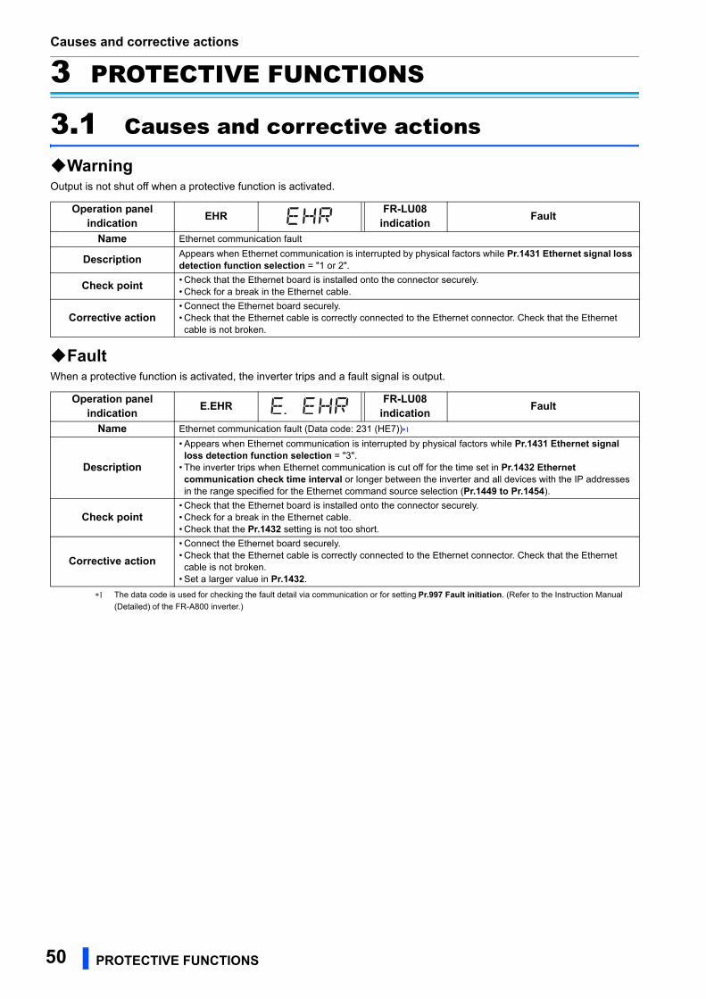
Causes and corrective actions
50 PROTECTIVE FUNCTIONS
3 PROTECTIVE FUNCTIONS
3.1 Causes and corrective actions
WarningOutput is not shut off when a protective function is activated.
FaultWhen a protective function is activated, the inverter trips and a fault signal is output.
The data code is used for checking the fault detail via communication or for setting Pr.997 Fault initiation. (Refer to the Instruction Manual
(Detailed) of the FR-A800 inverter.)
Operation panel indication
EHRFR-LU08
indicationFault
Name Ethernet communication fault
DescriptionAppears when Ethernet communication is interrupted by physical factors while Pr.1431 Ethernet signal loss detection function selection = "1 or 2".
Check point• Check that the Ethernet board is installed onto the connector securely.• Check for a break in the Ethernet cable.
Corrective action• Connect the Ethernet board securely.• Check that the Ethernet cable is correctly connected to the Ethernet connector. Check that the Ethernet cable is not broken.
Operation panel indication
E.EHRFR-LU08
indicationFault
Name Ethernet communication fault (Data code: 231 (HE7))
Description
• Appears when Ethernet communication is interrupted by physical factors while Pr.1431 Ethernet signal loss detection function selection = "3".
• The inverter trips when Ethernet communication is cut off for the time set in Pr.1432 Ethernet communication check time interval or longer between the inverter and all devices with the IP addresses in the range specified for the Ethernet command source selection (Pr.1449 to Pr.1454).
Check point• Check that the Ethernet board is installed onto the connector securely.• Check for a break in the Ethernet cable.• Check that the Pr.1432 setting is not too short.
Corrective action
• Connect the Ethernet board securely.• Check that the Ethernet cable is correctly connected to the Ethernet connector. Check that the Ethernet cable is not broken.
• Set a larger value in Pr.1432.
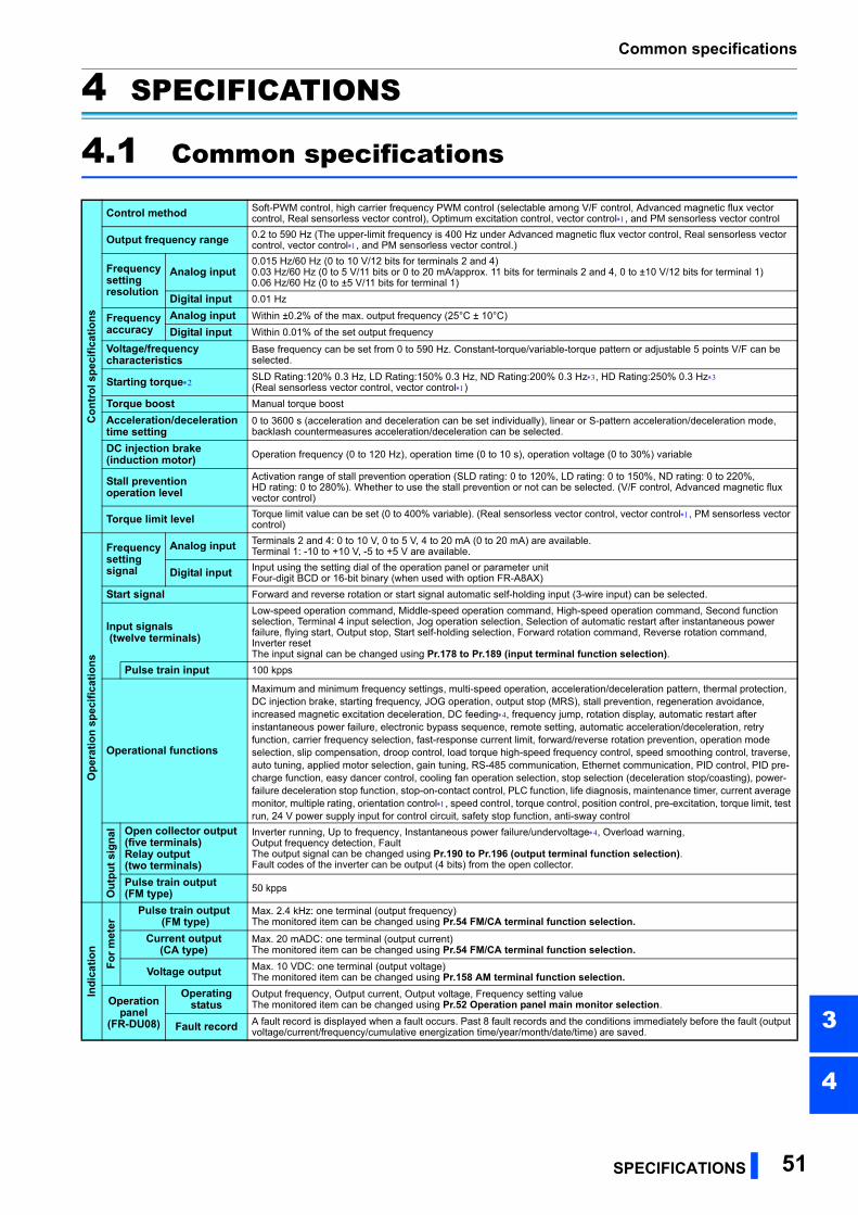
Common specifications
SPECIFICATIONS 51
3
4
4 SPECIFICATIONS
4.1 Common specifications
Co
ntr
ol s
pec
ific
ati
on
s
Control method Soft-PWM control, high carrier frequency PWM control (selectable among V/F control, Advanced magnetic flux vector control, Real sensorless vector control), Optimum excitation control, vector control, and PM sensorless vector control
Output frequency range 0.2 to 590 Hz (The upper-limit frequency is 400 Hz under Advanced magnetic flux vector control, Real sensorless vectorcontrol, vector control, and PM sensorless vector control.)
Frequency settingresolution
Analog input0.015 Hz/60 Hz (0 to 10 V/12 bits for terminals 2 and 4)0.03 Hz/60 Hz (0 to 5 V/11 bits or 0 to 20 mA/approx. 11 bits for terminals 2 and 4, 0 to ±10 V/12 bits for terminal 1)0.06 Hz/60 Hz (0 to ±5 V/11 bits for terminal 1)
Digital input 0.01 Hz
Frequency accuracy
Analog input Within ±0.2% of the max. output frequency (25°C ± 10°C)
Digital input Within 0.01% of the set output frequency
Voltage/frequency characteristics
Base frequency can be set from 0 to 590 Hz. Constant-torque/variable-torque pattern or adjustable 5 points V/F can be selected.
Starting torque SLD Rating:120% 0.3 Hz, LD Rating:150% 0.3 Hz, ND Rating:200% 0.3 Hz, HD Rating:250% 0.3 Hz(Real sensorless vector control, vector control)
Torque boost Manual torque boost
Acceleration/deceleration time setting
0 to 3600 s (acceleration and deceleration can be set individually), linear or S-pattern acceleration/deceleration mode, backlash countermeasures acceleration/deceleration can be selected.
DC injection brake (induction motor) Operation frequency (0 to 120 Hz), operation time (0 to 10 s), operation voltage (0 to 30%) variable
Stall prevention operation level
Activation range of stall prevention operation (SLD rating: 0 to 120%, LD rating: 0 to 150%, ND rating: 0 to 220%, HD rating: 0 to 280%). Whether to use the stall prevention or not can be selected. (V/F control, Advanced magnetic flux vector control)
Torque limit level Torque limit value can be set (0 to 400% variable). (Real sensorless vector control, vector control, PM sensorless vector control)
Op
erat
ion
sp
eci
fic
atio
ns
Frequency setting signal
Analog input Terminals 2 and 4: 0 to 10 V, 0 to 5 V, 4 to 20 mA (0 to 20 mA) are available.Terminal 1: -10 to +10 V, -5 to +5 V are available.
Digital input Input using the setting dial of the operation panel or parameter unitFour-digit BCD or 16-bit binary (when used with option FR-A8AX)
Start signal Forward and reverse rotation or start signal automatic self-holding input (3-wire input) can be selected.
Input signals (twelve terminals)
Low-speed operation command, Middle-speed operation command, High-speed operation command, Second function selection, Terminal 4 input selection, Jog operation selection, Selection of automatic restart after instantaneous power failure, flying start, Output stop, Start self-holding selection, Forward rotation command, Reverse rotation command, Inverter resetThe input signal can be changed using Pr.178 to Pr.189 (input terminal function selection).
Pulse train input 100 kpps
Operational functions
Maximum and minimum frequency settings, multi-speed operation, acceleration/deceleration pattern, thermal protection, DC injection brake, starting frequency, JOG operation, output stop (MRS), stall prevention, regeneration avoidance, increased magnetic excitation deceleration, DC feeding, frequency jump, rotation display, automatic restart after instantaneous power failure, electronic bypass sequence, remote setting, automatic acceleration/deceleration, retry function, carrier frequency selection, fast-response current limit, forward/reverse rotation prevention, operation mode selection, slip compensation, droop control, load torque high-speed frequency control, speed smoothing control, traverse, auto tuning, applied motor selection, gain tuning, RS-485 communication, Ethernet communication, PID control, PID pre-charge function, easy dancer control, cooling fan operation selection, stop selection (deceleration stop/coasting), power-failure deceleration stop function, stop-on-contact control, PLC function, life diagnosis, maintenance timer, current average monitor, multiple rating, orientation control, speed control, torque control, position control, pre-excitation, torque limit, test run, 24 V power supply input for control circuit, safety stop function, anti-sway control
Ou
tpu
t si
gn
al Open collector output
(five terminals)Relay output (two terminals)
Inverter running, Up to frequency, Instantaneous power failure/undervoltage, Overload warning, Output frequency detection, FaultThe output signal can be changed using Pr.190 to Pr.196 (output terminal function selection).Fault codes of the inverter can be output (4 bits) from the open collector.
Pulse train output(FM type) 50 kpps
Ind
ica
tio
n
Fo
r m
ete
r
Pulse train output (FM type)
Max. 2.4 kHz: one terminal (output frequency)The monitored item can be changed using Pr.54 FM/CA terminal function selection.
Current output(CA type)
Max. 20 mADC: one terminal (output current)The monitored item can be changed using Pr.54 FM/CA terminal function selection.
Voltage output Max. 10 VDC: one terminal (output voltage)The monitored item can be changed using Pr.158 AM terminal function selection.
Operation panel
(FR-DU08)
Operating status
Output frequency, Output current, Output voltage, Frequency setting valueThe monitored item can be changed using Pr.52 Operation panel main monitor selection.
Fault record A fault record is displayed when a fault occurs. Past 8 fault records and the conditions immediately before the fault (output voltage/current/frequency/cumulative energization time/year/month/date/time) are saved.
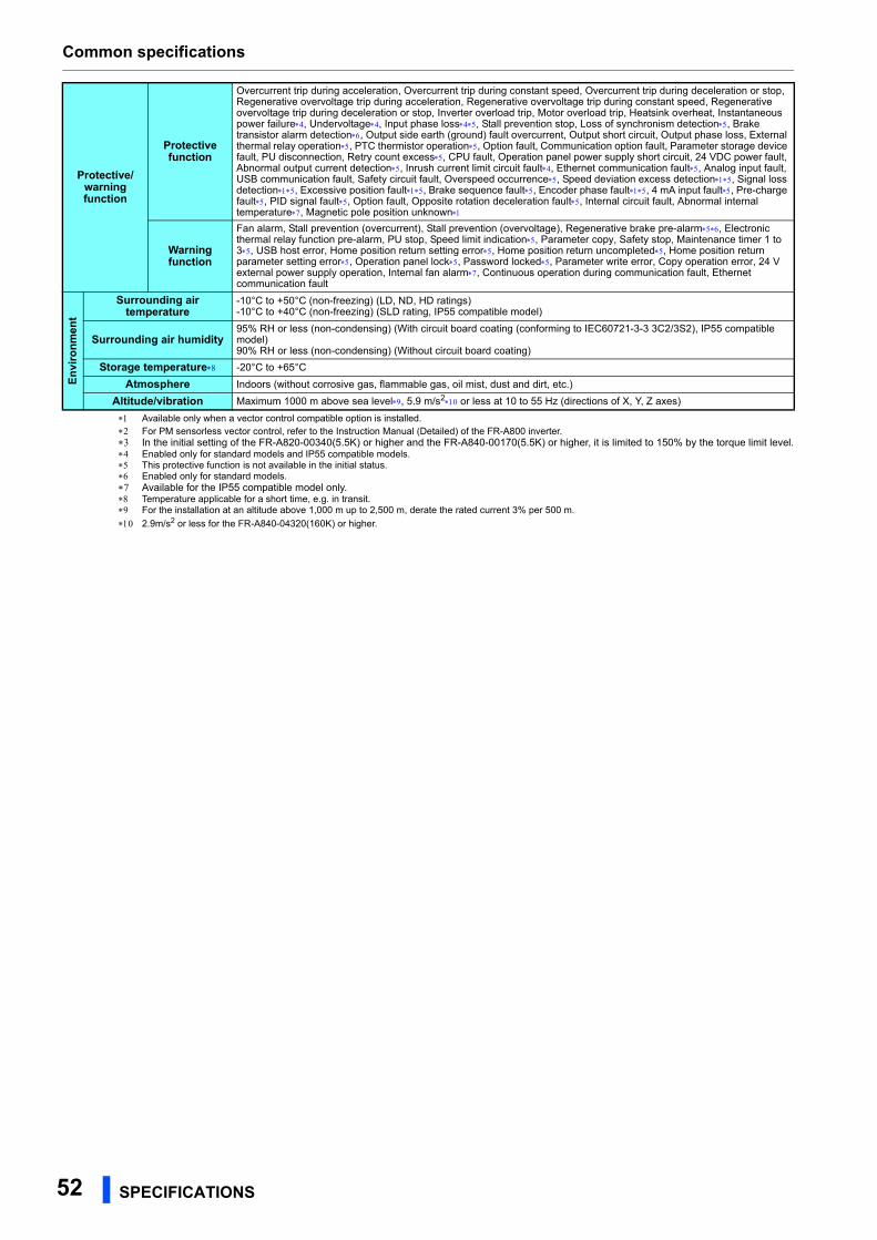
Common specifications
52 SPECIFICATIONS
Available only when a vector control compatible option is installed. For PM sensorless vector control, refer to the Instruction Manual (Detailed) of the FR-A800 inverter. In the initial setting of the FR-A820-00340(5.5K) or higher and the FR-A840-00170(5.5K) or higher, it is limited to 150% by the torque limit level. Enabled only for standard models and IP55 compatible models. This protective function is not available in the initial status. Enabled only for standard models. Available for the IP55 compatible model only. Temperature applicable for a short time, e.g. in transit. For the installation at an altitude above 1,000 m up to 2,500 m, derate the rated current 3% per 500 m.
2.9m/s2 or less for the FR-A840-04320(160K) or higher.
Protective/warning function
Protective function
Overcurrent trip during acceleration, Overcurrent trip during constant speed, Overcurrent trip during deceleration or stop, Regenerative overvoltage trip during acceleration, Regenerative overvoltage trip during constant speed, Regenerative overvoltage trip during deceleration or stop, Inverter overload trip, Motor overload trip, Heatsink overheat, Instantaneous power failure, Undervoltage, Input phase loss, Stall prevention stop, Loss of synchronism detection, Brake transistor alarm detection, Output side earth (ground) fault overcurrent, Output short circuit, Output phase loss, External thermal relay operation, PTC thermistor operation, Option fault, Communication option fault, Parameter storage device fault, PU disconnection, Retry count excess, CPU fault, Operation panel power supply short circuit, 24 VDC power fault, Abnormal output current detection, Inrush current limit circuit fault, Ethernet communication fault, Analog input fault, USB communication fault, Safety circuit fault, Overspeed occurrence, Speed deviation excess detection, Signal loss detection, Excessive position fault, Brake sequence fault, Encoder phase fault, 4 mA input fault, Pre-charge fault, PID signal fault, Option fault, Opposite rotation deceleration fault, Internal circuit fault, Abnormal internal temperature, Magnetic pole position unknown
Warning function
Fan alarm, Stall prevention (overcurrent), Stall prevention (overvoltage), Regenerative brake pre-alarm, Electronic thermal relay function pre-alarm, PU stop, Speed limit indication, Parameter copy, Safety stop, Maintenance timer 1 to 3, USB host error, Home position return setting error, Home position return uncompleted, Home position return parameter setting error, Operation panel lock, Password locked, Parameter write error, Copy operation error, 24 V external power supply operation, Internal fan alarm, Continuous operation during communication fault, Ethernet communication fault
En
viro
nm
ent
Surrounding air temperature
-10°C to +50°C (non-freezing) (LD, ND, HD ratings)-10°C to +40°C (non-freezing) (SLD rating, IP55 compatible model)
Surrounding air humidity95% RH or less (non-condensing) (With circuit board coating (conforming to IEC60721-3-3 3C2/3S2), IP55 compatible model)90% RH or less (non-condensing) (Without circuit board coating)
Storage temperature -20°C to +65°C
Atmosphere Indoors (without corrosive gas, flammable gas, oil mist, dust and dirt, etc.)
Altitude/vibration Maximum 1000 m above sea level, 5.9 m/s2 or less at 10 to 55 Hz (directions of X, Y, Z axes)
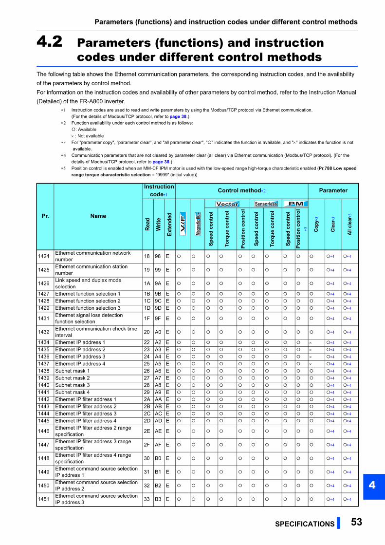
Parameters (functions) and instruction codes under different control methods
SPECIFICATIONS 53
4
4.2 Parameters (functions) and instruction codes under different control methods
The following table shows the Ethernet communication parameters, the corresponding instruction codes, and the availability
of the parameters by control method.
For information on the instruction codes and availability of other parameters by control method, refer to the Instruction Manual
(Detailed) of the FR-A800 inverter.
Instruction codes are used to read and write parameters by using the Modbus/TCP protocol via Ethernet communication.
(For the details of Modbus/TCP protocol, refer to page 38.)
Function availability under each control method is as follows:
: Available
: Not available
For "parameter copy", "parameter clear", and "all parameter clear", "" indicates the function is available, and "" indicates the function is not
available.
Communication parameters that are not cleared by parameter clear (all clear) via Ethernet communication (Modbus/TCP protocol). (For the
details of Modbus/TCP protocol, refer to page 38.)
Position control is enabled when an MM-CF IPM motor is used with the low-speed range high-torque characteristic enabled (Pr.788 Low speed
range torque characteristic selection = "9999" (initial value)).
Pr. Name
Instructioncode
Control method Parameter
Rea
d
Wri
te
Ext
ende
d
Cop
y
Cle
ar
All
clea
r
Sp
eed
co
ntr
ol
Torq
ue
con
tro
l
Po
siti
on
co
ntr
ol
Sp
eed
co
ntr
ol
Torq
ue
con
tro
l
Sp
eed
co
ntr
ol
Po
siti
on
co
ntr
ol
1424Ethernet communication network number
18 98 E
1425Ethernet communication station number
19 99 E
1426Link speed and duplex mode selection
1A 9A E
1427 Ethernet function selection 1 1B 9B E
1428 Ethernet function selection 2 1C 9C E
1429 Ethernet function selection 3 1D 9D E
1431Ethernet signal loss detection function selection
1F 9F E
1432Ethernet communication check time interval
20 A0 E
1434 Ethernet IP address 1 22 A2 E
1435 Ethernet IP address 2 23 A3 E
1436 Ethernet IP address 3 24 A4 E
1437 Ethernet IP address 4 25 A5 E
1438 Subnet mask 1 26 A6 E
1439 Subnet mask 2 27 A7 E
1440 Subnet mask 3 28 A8 E
1441 Subnet mask 4 29 A9 E
1442 Ethernet IP filter address 1 2A AA E
1443 Ethernet IP filter address 2 2B AB E
1444 Ethernet IP filter address 3 2C AC E
1445 Ethernet IP filter address 4 2D AD E
1446Ethernet IP filter address 2 range specification
2E AE E
1447Ethernet IP filter address 3 range specification
2F AF E
1448Ethernet IP filter address 4 range specification
30 B0 E
1449Ethernet command source selection IP address 1
31 B1 E
1450Ethernet command source selection IP address 2
32 B2 E
1451Ethernet command source selection IP address 3
33 B3 E
V/F
V/F
V/F
Magn
etic f
luxMa
gneti
c flux
Magn
etic f
luxVectorVectorVector SensorlessSensorlessSensorless PMPMPM

Parameters (functions) and instruction codes under different control methods
54 SPECIFICATIONS
1452Ethernet command source selection IP address 4
34 B4 E
1453Ethernet command source selection IP address 3 range specification
35 B5 E
1454Ethernet command source selection IP address 4 range specification
36 B6 E
1455 Keepalive time 37 B7 E
Pr. Name
Instructioncode
Control method Parameter
Rea
d
Wri
te
Ext
ende
d
Cop
y
Cle
ar
All
clea
r
Sp
eed
co
ntr
ol
Torq
ue
con
tro
l
Po
siti
on
co
ntr
ol
Sp
eed
co
ntr
ol
Torq
ue
con
tro
l
Sp
eed
co
ntr
ol
Po
siti
on
co
ntr
ol
V/F
V/F
V/F
Magn
etic f
luxMa
gneti
c flux
Magn
etic f
lux
VectorVectorVector SensorlessSensorlessSensorless PMPMPM

55
REVISIONS
*The manual number is given on the bottom left of the back cover.
Print Date *Manual Number RevisionMay 2016 IB(NA)-0600628ENG-A First edition

IB(NA)-0600628ENG-A(1605) MEE Printed in Japan Specifications subject to change without notice.
HEAD OFFICE: TOKYO BUILDING 2-7-3, MARUNOUCHI, CHIYODA-KU, TOKYO 100-8310, JAPAN