framework for design & planning of lv · pdf fileassociated street lighting installations...
TRANSCRIPT

FRAMEWORK FOR DESIGN & PLANNING OF LV HOUSING DEVELOPMENTS, INCLUDING U/G
NETWORKS AND ASSOCIATED HV/LV S/S
ESDD-02-012 Issue No 6
© SP Power Systems Limited Page 1 of 32 Design Manual (SPD, SPM): Section 5d
1. SCOPE
This document details the SP Distribution Limited and SP Manweb plc requirements for the design of low voltage underground cable electricity networks including their new associated HV / LV distribution substations. The document specifically relates to housing estates constructed under Ofgem’s Competition in Connections regime. This document does not detail arrangements for multi-occupied premises or industrial / commercial supplies. The document forms the appendix to, and must be read in conjunction with, G81 – the Electricity Association publication titled: Framework for design and planning, materials specification and installation and record for low voltage housing developments underground network installations and associated, new, HV/LV distribution substations. This document only applies to new developments comprising of single-occupied premises and their associated street lighting installations and is not to be applied retrospectively.
2. ISSUE RECORD
This is a Controlled document. The current version is held on the EN Document Library. It is your responsibility to ensure you work to the current version.
Issue Date Issue No.
Author Amendment Details
June 2011 Issue 4 D Carson Update to Demand Estimator to reflect lowered ADMDs together with some minor document revisions
May 2013 Issue 5 N Gourley Update to Appendix D - Cable Electrical & Rating Data to align cable ratings with SP Energy Networks rating schedules. Inclusion of ADMD for Heat Pump installations.
20th October 2016 Issue 6 Jonathan Mitchell Amendment to section 10.5 (n) only to
remove ambiguity of requirement to terminate additional cables to spare fuse ways on take-off chamber and LV Boards.
3. ISSUE AUTHORITY
Author Owner Issue Authority
Jonathan Mitchell Senior Project Engineer Design
Malcolm Bebbington Distribution Network Manager (SPM) David Neilson Distribution Network Manager (SPD)
Malcolm Bebbington Distribution Network Manager (SPM)
Date: ...10-11-16...................

FRAMEWORK FOR DESIGN & PLANNING OF LV HOUSING DEVELOPMENTS, INCLUDING U/G
NETWORKS AND ASSOCIATED HV/LV S/S
ESDD-02-012 Issue No 6
© SP Power Systems Limited Page 2 of 32 Design Manual (SPD, SPM): Section 5d
4. REVIEW
This is a Controlled document and shall be reviewed as detailed in the main document indexes of the Design Manuals or as dictated by business / legislative change, but at a period of no greater than five years from the last issue date. The reference numbers for the index documents are as follows: SP Distribution DOC-00-206 SP Manweb DOC-00-310
5. DISTRIBUTION
This document is part of the SP Distribution / Manweb Design Manual(s) and does not have a maintained distribution list.

FRAMEWORK FOR DESIGN & PLANNING OF LV HOUSING DEVELOPMENTS, INCLUDING U/G
NETWORKS AND ASSOCIATED HV/LV S/S
ESDD-02-012 Issue No 6
© SP Power Systems Limited Page 3 of 32 Design Manual (SPD, SPM): Section 5d
6. CONTENTS
1. SCOPE ....................................................................................................................................... 1
2. ISSUE RECORD ........................................................................................................................ 1
3. ISSUE AUTHORITY .................................................................................................................. 1
4. REVIEW ..................................................................................................................................... 2
5. DISTRIBUTION .......................................................................................................................... 2
6. CONTENTS ............................................................................................................................... 3
7. DEFINITIONS AND ABBREVIATIONS ..................................................................................... 4
8. RELATED DOCUMENTS .......................................................................................................... 6
9. GENERAL .................................................................................................................................. 6
10. NETWORK PRINCIPLES .......................................................................................................... 8
10.1 SECURITY OF SUPPLY ..................................................................................................... 8
10.2 Plant, Equipment and Materials ....................................................................................... 8
10.3 Establishing the Point of Connection ............................................................................. 9
10.4 LV Design Considerations ................................................................................................ 9
10.5 HV Network and Substation Design Considerations ................................................... 10
10.6 Substation Interconnection ............................................................................................ 13
10.7 Specific Interconnection Issue In Parts of SP Manweb Plc Network Area ................ 14
10.8 Phased Developments .................................................................................................... 15
11. DETAILED DESIGN GUIDANCE ............................................................................................ 16
11.1 Service Cables and Service Ducts ................................................................................. 17
11.2 Street Lighting Services ................................................................................................. 18
11.3 High/Low Voltage Mains Cables .................................................................................... 18
11.4 Demand Estimator ........................................................................................................... 19
11.5 Cable Rating ..................................................................................................................... 20
11.6 Quality of Supply ............................................................................................................. 20
11.7 Approved Voltage Drop Calculation Method ................................................................ 21
11.8 Low Voltage Earthing and Bonding ............................................................................... 21
11.9 Short Circuit Currents ..................................................................................................... 22
12. DESIGN APPROVAL .............................................................................................................. 23
APPENDIX A – MINIMUM INFORMATION TEMPLATE FOR INDICATIVE CONNECTION COST . ................................................................................................................................................. 24
APPENDIX B - MINIMUM INFORMATION TEMPLATE FOR QUOTATION ................................. 25
APPENDIX C - MINIMUM INFORMATION TEMPLATE FOR DESIGN APPROVAL AND QUOTATION ................................................................................................................................... 26
APPENDIX D - CABLE ELECTRICAL & RATING DATA .............................................................. 28

FRAMEWORK FOR DESIGN & PLANNING OF LV HOUSING DEVELOPMENTS, INCLUDING U/G
NETWORKS AND ASSOCIATED HV/LV S/S
ESDD-02-012 Issue No 6
© SP Power Systems Limited Page 4 of 32 Design Manual (SPD, SPM): Section 5d
7. DEFINITIONS AND ABBREVIATIONS
ADMD After Diversity Maximum Demand
Applicant The organisation (or their representative) responsible for the overall design and development of the Housing Site. Typically referred to as the Client or Principal contractor under the CDM regulations.
Approved Policy and design parameters contained within this document and its appendices or the written approval of SP Distribution Ltd / SP Manweb plc.
CDM The Construction (Design and Management) Regulations 1994.
CNE Combined neutral and earth (of cable construction).
Common Access Parts of the development to which all residents / SP Distribution Ltd / SP Manweb plc representatives have unrestricted access.
Customer The recipients of the power supply being a tenant or owner of a domestic dwelling.
Distributors A main electricity cable laid externally in the ground and supplying more than one Customer.
External Meter Cupboard
A cupboard, positioned external to the property and containing the customer’s Point of Supply.
Greenfield A plot of land that has not been subject to any form of development.
Housing Site A development consisting of domestic dwellings.
Incoming Supply Cable An electricity cable connecting the building to the SP Distribution Ltd / SP Manweb plc network.
Interconnection Cables that have more than one supply source available. Full Interconnection refers to cables that run normally with more than one supply source in use as found in unit protected networks.
Link Boxes A device buried in the ground but accessible from street level that enables cables to be isolated by the removal of links.
Mains See distributor definition.
Network Pillars An outdoor cupboard arrangement that enables cables to be isolated by the removal of links / fuses.
New Connection Contractor Independent contractor wishing to undertake Contestable Work within the Company’s licensed area, as detailed in Energy Networks document ASSET-01-015.
NRSWA New Roads and Street Works Act.
PME Protective multiple earthing.

FRAMEWORK FOR DESIGN & PLANNING OF LV HOUSING DEVELOPMENTS, INCLUDING U/G
NETWORKS AND ASSOCIATED HV/LV S/S
ESDD-02-012 Issue No 6
© SP Power Systems Limited Page 5 of 32 Design Manual (SPD, SPM): Section 5d
Point of Connection The position at which a developer’s network would connect to the existing distribution system.
PSCC Prospective Short Circuit Current
Point of Supply The point at which the ownership of the electrical cable network passes from SP Distribution Ltd / SP Manweb plc to the Customer.
Energy Networks SP Energy Networks Ltd, operator of network assets on behalf of the Company
Service A cable providing supply to an individual house.
Service Position The location in the Customer’s property at which the SP Distribution Ltd / SP Manweb plc cable termination (cut-out) is located.
Service Strips A clear route through a Housing Site containing utility infrastructure.
SP Distribution Ltd The Distribution Licence Holder for the Distribution Service area formerly known as Scottish Power.
SP Manweb plc The Distribution Licence Holder for the Distribution Service area formerly known as Manweb.
The Company
A term used throughout this document to refer to both SP Distribution Limited and SP Manweb plc including all associated design and planning practices.

FRAMEWORK FOR DESIGN & PLANNING OF LV HOUSING DEVELOPMENTS, INCLUDING U/G
NETWORKS AND ASSOCIATED HV/LV S/S
ESDD-02-012 Issue No 6
© SP Power Systems Limited Page 6 of 32 Design Manual (SPD, SPM): Section 5d
8. RELATED DOCUMENTS
This document is one of a suite of specifications relating to this subject area and should be read in conjunction with: (a) Statutory Legislation
The Electricity Safety, Quality and Continuity Regulations 2002
New Roads and Street Works Act 1991
Construction (Design and Management) Regulations 1994
(b) British Standards
BS 7671 Requirements for Electrical Installations – IEE Wiring Regulations
BS 7430 Code of practice for Earthing
(c) National Joint Utilities Group (NJUG) Publications Guidelines on the positioning and colour coding of Utilities’ apparatus
(d) Energy Network Association Documents:
Engineering Recommendation G81 - Framework for design and planning, materials specification and installation and record for Greenfield low voltage housing estate installations and associated new, HV / LV distribution substations.
Part 1: Design and Planning
Part 2: Materials Specification
Part 3: Installation and Records
Engineering Recommendation G12/4 (1995): Requirements for the application of protective multiple earthing to low voltage networks
Engineering Recommendation P2/6 (2006): Security of Supply
Engineering Recommendation P28 (1989): Planning limits for voltage fluctuations caused by industrial, commercial and domestic equipment in the United Kingdom
Engineering Recommendation P29 (1990): Planning limits for voltage unbalance in the UK for 132kV and below
Engineering Recommendation G5/4-1: Planning levels for harmonic voltage distortion & the connection of non-linear equipment to transmission systems & distribution networks in the United Kingdom.
(e) Energy Networks Internal Documents:
Materials Specification framework for Greenfield low voltage housing estate installations and associated new HV/LV distribution substations (Ref. EPS-03-027).
Installation and Records framework for Greenfield low voltage housing estate installations and associated new HV/LV distribution substations (Ref. EPS-02-005).
Secondary Substation specification and installation SUB-02-006
Approved Equipment Register - Switchgear SWG-06-001
New Connection Contractor Approval Policy ASSET-01-015 All authorised designs must comply with both the requirements described within this document and those detailed above.
9. GENERAL
The data and guidance contained within this document remains the property of Energy Networks and may not be used for purposes other than that for which it has been supplied and may not be reproduced either wholly or in part, in any way whatsoever, nor may it be used by, or its contents divulged to, any other person whosoever, without the prior written permission of Energy Networks. This document applies to new installations and is not to be applied retrospectively.

FRAMEWORK FOR DESIGN & PLANNING OF LV HOUSING DEVELOPMENTS, INCLUDING U/G
NETWORKS AND ASSOCIATED HV/LV S/S
ESDD-02-012 Issue No 6
© SP Power Systems Limited Page 7 of 32 Design Manual (SPD, SPM): Section 5d
Energy Networks reserves the right to change the data contained within this document without notification. Although specific network extensions will be designed by third parties, Energy Networks retains the overall responsibility for the design of the distribution system and since the guidance cannot cover every eventuality, reserve the right to apply other criteria where necessary. Energy Networks accepts no responsibility for any inaccuracies in, or omissions from the document. The Applicant is responsible for ensuring they have all relevant information to undertake the design. Only Applicants possessing the appropriate skills, training and experience shall use the data and guidance contained within this document. The requirements detailed within this document should be considered as minimum requirements. Commercial apportionment rules are applicable where indicated although the costs associated with the establishment of the infrastructure will generally be borne by the developer. At the discretion of the developer and where considered economic, incremental works may be undertaken again, in general, with the costs being borne by the developer. Energy Networks may nominate a contractor to undertake some or all of its non-contestable obligations. In addition to the requirements of this document prior to design approval and subsequent adoption of networks New Connection Contractors shall adhere to the requirements detailed in the New Connection Contractor Approval Policy (ASSET-01-015). The data and guidance contained within this document details the electrical design only and does not embrace the physical construction of the distribution system or the associated safety, environmental and legal requirements.

FRAMEWORK FOR DESIGN & PLANNING OF LV HOUSING DEVELOPMENTS, INCLUDING U/G
NETWORKS AND ASSOCIATED HV/LV S/S
ESDD-02-012 Issue No 6
© SP Power Systems Limited Page 8 of 32 Design Manual (SPD, SPM): Section 5d
10. NETWORK PRINCIPLES
10.1 SECURITY OF SUPPLY
The minimum design requirement will satisfy Engineering Recommendation P2/6, comply with Energy Networks’ policy as detailed in this document and will ensure the technical and performance characteristics of the existing network infrastructure are not compromised below Energy Networks’ acceptable minimum standards. However it should be noted that P2/6 is not applicable to individual end customers (applies to Demand Groups) so specific solutions may be offered to meet an individual customer’s requirements. The connection of a new or additional load must not adversely affect the performance of the existing network or the security of supply provided to existing customers to levels below PowerSystem’s minimum acceptable standards. Applicants must ensure that customers are made aware of (and understand) all possible connection arrangements which can vary the level of supply security for specific connections. Energy Networks will recommend a minimum level of security believed appropriate to the customer’s needs – known in this document as Energy Networks recommended design solution. Security of supply issues include the ability to restore the network following a fault, the continuity of supply as construction proceeds and continuity of supply during maintenance of the local network. This may be particularly relevant to larger developments, where the alternative means of supply may not be available until completion of the final phase of the development, some years ahead. Networks shall be designed to limit the number of customers affected by any fault and to facilitate the shortest restoration and repair times. Likewise, networks shall be designed to minimise system losses.
10.2 Plant, Equipment and Materials
All plant, equipment and materials and their associated installation shall comply with the appropriate specifications for work in the Company’s network areas. These are available upon request and cover such matters as the installation requirements, the arrangement of equipment at the Service termination and the depths / lateral position of cables and ducts. Only Energy Networks Approved plant, equipment and materials shall be used. Only NEW plant, equipment and materials shall be installed unless prior agreement is obtained from Energy Networks. For further information reference should be made to the document: Materials specification framework for Greenfield low voltage housing estate underground network installations and associated, new, HV/LV distribution substations. Under no circumstances shall plant rated with non-standard Company system voltages be connected to the distribution network.

FRAMEWORK FOR DESIGN & PLANNING OF LV HOUSING DEVELOPMENTS, INCLUDING U/G
NETWORKS AND ASSOCIATED HV/LV S/S
ESDD-02-012 Issue No 6
© SP Power Systems Limited Page 9 of 32 Design Manual (SPD, SPM): Section 5d
10.3 Establishing the Point of Connection
Energy Networks will provide an indicative Point of Connection onto the Company network based on the load information provided by the Applicant (refer to Appendix A and B). Energy Networks will carry out the necessary system design to specify the lowest cost practical point(s) of connection to the existing distribution system. For housing developments, the Point of Connection will normally be either an existing low voltage Main(s), the outgoing fuseway(s) of an existing low voltage substation or an existing high voltage Main(s) (requiring a secondary substation) and/or existing extra high voltage Main(s) (requiring a primary substation). Upstream from the Point of Connection, Energy Networks will design high voltage or high voltage / low voltage systems as appropriate and will advise: (a) The characteristics of the high / low voltage system at the point(s) of connection. (b) Any additional requirements for low voltage and high voltage Mains cables through the site
and any diversionary works required to accommodate the site. (c) Where appropriate and if provided with sufficient information, the type and approximate
preferred location of substation(s). The objective is to provide sufficient information to enable the high / low voltage distribution system design and layout beyond the point(s) of connection to be undertaken by the applicant. Where appropriate, an estimate will be provided for reinforcement of the existing upstream distribution system to accommodate the additional load at the point(s) of connection.
10.4 LV Design Considerations
As a minimum, the design shall ensure that the following requirements are met (these are discussed in more detail later within this document). Each domestic property and streetlight is afforded a standard connection arrangement that meets the technical requirements of voltage, frequency and loop impedance. Suitable Approved customer isolator switches shall be installed at the Service position. The electrical installation beyond the Point of Connection for dwellings and street lighting shall comply with 17th Edition Wiring regulations, BS7671 Code of practice for earthing BS7430 and where relevant (SP Manweb plc area) W547 ‘Notes of Guidance for Installation Designers and Electrical Contractors.’ The distributors must be designed to experience a balanced load that is within their rating. The design must be such that the substation fuses will operate to clear faults on the distributors and Services. Only Company Approved fuse sizes and types shall be used. A full listing of Approved fuse types is in document SWG-02-008, Approved Equipment Register – Switchgear section. To assist in customer restoration during LV cable faults a maximum of 75 Customers shall be connected to a radial LV feeder. LV feeders with a Customer count in excess of this shall be provided with a suitable backfeed. However in certain circumstances and where reasonably practicable Energy Networks can insist on a suitable backfeed for LV feeders with less than 75 Customers. This backfeed can be controlled from the same substation. Cables with 75 customers or more and cables used as backfeeds shall have a minimum conductor cross sectional area of 185mm
2

FRAMEWORK FOR DESIGN & PLANNING OF LV HOUSING DEVELOPMENTS, INCLUDING U/G
NETWORKS AND ASSOCIATED HV/LV S/S
ESDD-02-012 Issue No 6
© SP Power Systems Limited Page 10 of 32 Design Manual (SPD, SPM): Section 5d
10.5 HV Network and Substation Design Considerations
As a minimum, the design shall ensure that the following requirements are met. Where relevant, these are discussed in more detail within this document. (a) HV cables for network extensions shall be selected to ensure that there is no de-rating of the
existing overall circuit and shall be of an Approved design. (b) Only Energy Networks Approved, 500 kVA and 1000 kVA 3 phase transformers are
acceptable depending on the overall load. In LV networks operating interconnected (e.g. SP Manweb plc’s X – type network), only 500 kVA transformers shall be used.
(c) In areas where 6.6 kV networks exist, dual ratio (11/ 6.6 kV) transformers shall be installed.
Similarly dual ratio transformers will be required for networks operating at 6kV or 6.3kV. (d) For smaller sites in rural areas having a total ADMD load less than 200 kVA, an Approved
pole-mounted transformer arrangement may be used. In such cases, 200 kVA, 100 kVA, 50 kVA 3-phase transformer sizes and 50 kVA or 25 kVA single-phase transformers are acceptable.
For the purpose of housing developments only, the transformer nameplate ratings as detailed in (b) and (d) above may be exceeded by cyclic loads up to a maximum of 30% for a 6 hour period in any 24 hours providing that the remainder of that time the transformer is loaded to no more than 80% of its nameplate rating.
(e) All HV overhead lines shall be designed to the relevant Energy Networks specification. (f) The HV network connection for both pole mounted transformers and HV overhead lines shall
only be to a radial HV circuit with suitable protection complying with paragraph (g). Neither pole mounted transformers nor HV overhead lines shall be directly connected to interconnected HV circuits in the SP Manweb plc area. To meet these requirements it may be necessary to establish a new radial HV circuit through the installation of Approved HV switchgear.
(g) The source circuit breaker protecting HV pole mounted equipment (including pole mounted
transformers, cable terminations, etc) shall be equipped with earth fault protection. The circuit breaker protecting one or more spans of HV overhead line shall be equipped with sensitive earth fault protection.
(h) Transformers shall never be directly breeched onto the HV Main and shall always be
connected via Approved HV switchgear that provides transformer protection (fuses or circuit breaker).
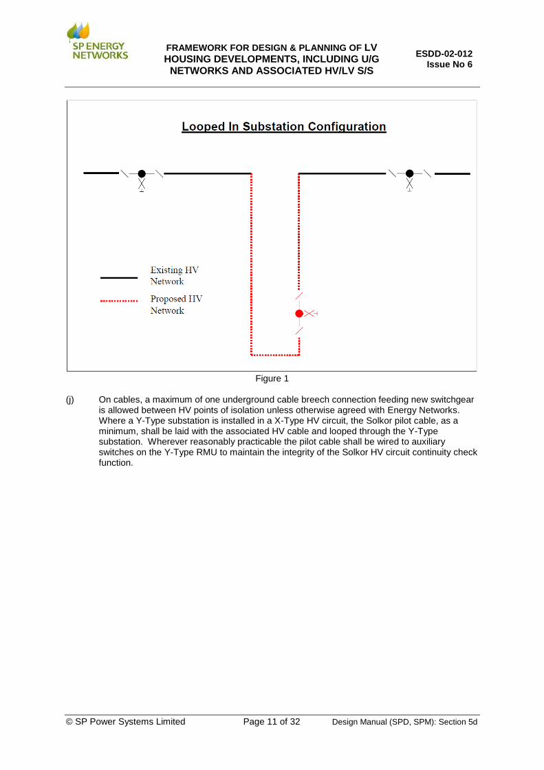
(i) New substations will be looped into the HV network, as shown in Figure 1, when one of the
following criteria is satisfied. • 250 Customers or more (or 500 kVA equivalent load) • 200 customers or more and 250m or less from the 11kV point of connection • 150 customers or more and 150m or less from the 11kV point of connection • 100 customers or more and 100m or less from the 11kV point of connection
FRAMEWORK FOR DESIGN & PLANNING OF LV HOUSING DEVELOPMENTS, INCLUDING U/G
NETWORKS AND ASSOCIATED HV/LV S/S
ESDD-02-012 Issue No 6
© SP Power Systems Limited Page 11 of 32 Design Manual (SPD, SPM): Section 5d
Figure 1
(j) On cables, a maximum of one underground cable breech connection feeding new switchgear
is allowed between HV points of isolation unless otherwise agreed with Energy Networks. Where a Y-Type substation is installed in a X-Type HV circuit, the Solkor pilot cable, as a minimum, shall be laid with the associated HV cable and looped through the Y-Type substation. Wherever reasonably practicable the pilot cable shall be wired to auxiliary switches on the Y-Type RMU to maintain the integrity of the Solkor HV circuit continuity check function.
FRAMEWORK FOR DESIGN & PLANNING OF LV HOUSING DEVELOPMENTS, INCLUDING U/G
NETWORKS AND ASSOCIATED HV/LV S/S
ESDD-02-012 Issue No 6
© SP Power Systems Limited Page 12 of 32 Design Manual (SPD, SPM): Section 5d
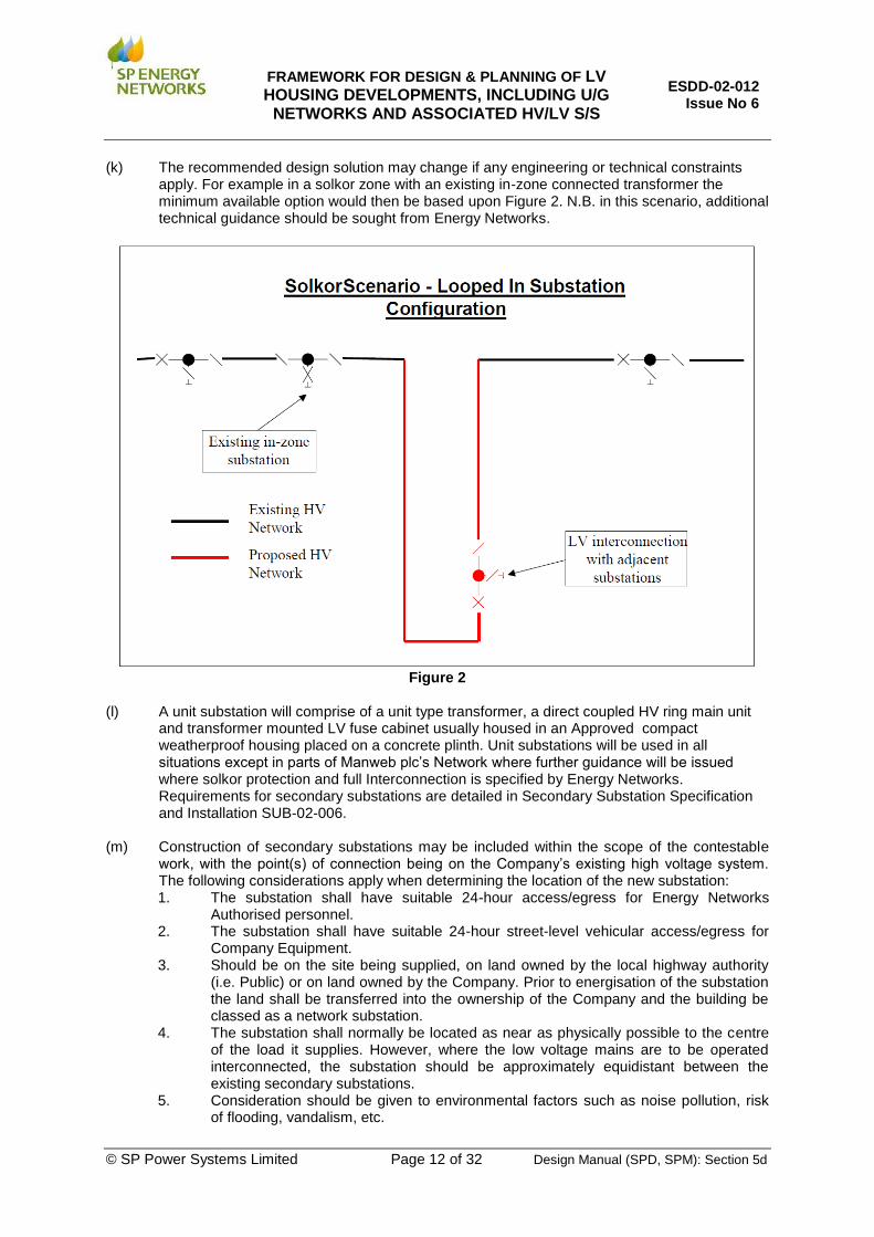
(k) The recommended design solution may change if any engineering or technical constraints apply. For example in a solkor zone with an existing in-zone connected transformer the minimum available option would then be based upon Figure 2. N.B. in this scenario, additional technical guidance should be sought from Energy Networks.
Figure 2
(l) A unit substation will comprise of a unit type transformer, a direct coupled HV ring main unit
and transformer mounted LV fuse cabinet usually housed in an Approved compact weatherproof housing placed on a concrete plinth. Unit substations will be used in all situations except in parts of Manweb plc’s Network where further guidance will be issued where solkor protection and full Interconnection is specified by Energy Networks. Requirements for secondary substations are detailed in Secondary Substation Specification and Installation SUB-02-006.
(m) Construction of secondary substations may be included within the scope of the contestable
work, with the point(s) of connection being on the Company’s existing high voltage system. The following considerations apply when determining the location of the new substation: 1. The substation shall have suitable 24-hour access/egress for Energy Networks
Authorised personnel. 2. The substation shall have suitable 24-hour street-level vehicular access/egress for
Company Equipment. 3. Should be on the site being supplied, on land owned by the local highway authority
(i.e. Public) or on land owned by the Company. Prior to energisation of the substation the land shall be transferred into the ownership of the Company and the building be classed as a network substation.
4. The substation shall normally be located as near as physically possible to the centre of the load it supplies. However, where the low voltage mains are to be operated interconnected, the substation should be approximately equidistant between the existing secondary substations.
5. Consideration should be given to environmental factors such as noise pollution, risk of flooding, vandalism, etc.

FRAMEWORK FOR DESIGN & PLANNING OF LV HOUSING DEVELOPMENTS, INCLUDING U/G
NETWORKS AND ASSOCIATED HV/LV S/S
ESDD-02-012 Issue No 6
© SP Power Systems Limited Page 13 of 32 Design Manual (SPD, SPM): Section 5d
(n) For compliance with the CDM regulations, all ground mounted substations with Fuse Cabinets (Take Off Chambers), freestanding pillars, and LV Boards, will have short lengths of LV Mains cables pot-ended no less than 2m outside the substation building on each spare way. This includes the following activities:-
1. Establishing a new LV Fuse Cabinets (Take Off Chambers), Free Standing Pillars
and LV Boards. 2. Any works associated with terminating new LV cables on to legacy switchgear, where
further spare LV ways remain available. 3. Modernisation/replacement of existing Fuse Cabinets (Take Off Chambers), Free
Standing Pillars and LV Boards. These cables will be a minimum of 300mm
2 conductor cross sectional area Waveform in SP
Distribution Ltd and in SP Manweb plc 185 mm2 conductor cross sectional area Waveform for
transformers up to and including 500kVA and 300 mm2 conductor cross sectional area waveform for
transformer sizes above 500kVA.
10.6 Substation Interconnection
Substations should be interconnected on the low voltage network to facilitate maintenance of substation plant and to speed post fault restoration. Interconnection by LV cables should normally be provided to the extent of one third of the substation’s ultimate load providing an accessible LV source is available. It is to be assumed that the normal load on the interconnecting LV cables is reduced to one third of their maximum connected load when assessing the available Interconnection capacity. Link Boxes if used are only to be provided at points where it is necessary to provide Interconnection and the number of cableways should not normally exceed two. However, their use should not be encouraged and all other design options must be considered before they are installed. Network Pillars shall not be used. In order to comply with the CDM regulations, consideration shall be given to performing additional LV work prior to energising Link Boxes. This would apply where it is known that this additional work will be required and a shutdown will be avoided. Hence while installing Link Boxes where not all the cableways will be utilised, LV mains cables pot-ended no less than 2 m from the Link Box shall be installed on each spare way. These cables will be a minimum of 185 mm
2 conductor cross sectional
area Waveform in SP Distribution Ltd. and in SP Manweb plc. The system would normally run with links / fuses on interconnected circuits removed.

FRAMEWORK FOR DESIGN & PLANNING OF LV HOUSING DEVELOPMENTS, INCLUDING U/G
NETWORKS AND ASSOCIATED HV/LV S/S
ESDD-02-012 Issue No 6
© SP Power Systems Limited Page 14 of 32 Design Manual (SPD, SPM): Section 5d
10.7 Specific Interconnection Issue In Parts of SP Manweb Plc Network Area
In parts of the SP Manweb plc network area, full Interconnection is possible due to the historically applied network design philosophy. In such areas the SP Manweb plc system would normally run with links / fuses on Interconnected circuits inserted in such a manner that the substation load can be fully supported by LV Interconnection during HV outages. However, new network extensions do not always require full Interconnection and the Company will provide site-specific guidance where it is considered necessary. When designing Interconnection between secondary substations it is necessary to consider both the LV and HV networks since not all substations can be operated with low voltage Interconnection. Where practicable in unit protected schemes at least 3 fuseways per substation should provide Interconnection with 3 other substations. Link Boxes are only to be provided at points where it is necessary to provide Interconnection and the number of cableways should not normally exceed four. All other design options must be considered before they are installed and guidance sought form Energy Networks. In order to reduce the lifting and handling issues, 2 way Link Boxes should be used where possible in preference to 4 way. Network Pillars shall not be used. An LV cable used to interconnect substations should connect a fuseway in one substation to a fuseway in up to two other substations. Where interconnectors are direct from substation to one other substation and 315 Amp fuses are used, the cable length between the two substations should not exceed 786 m of 185 mm2 conductor cross sectional area waveform cable. On existing LV networks it may not be practicable to achieve adequate Interconnection without using three circuits, each from a different substation to feed into a common interconnector. However, all designs must ensure it is not possible for an LV fault to be fed from more than three separate 315 Amp fuseways. Where three substations feed into a common interconnector, the cable length between any two substations should not exceed 545 m of 185 mm2 conductor cross sectional area waveform cable. In networks utilising full Interconnection the maximum cable run lengths highlighted in Table 1 shall not be exceeded.
Substation Fuse Size Configuration of LV Mains Cable Size
Maximum Length
(Amps) (metres)
315 Pure Radial 95W 328
315 Pure Radial 185W 728
400 Pure Radial 300W 710
315 Two way interconnector 185W 786
400 Two way interconnector 185W 605
315 Three way interconnector 185W 545
400 Three way interconnector 185W 421
Table 1: Maximum Cable Lengths
It shall not be possible for more than one fuseway in a particular secondary substation to feed into the same LV fault. The design shall ensure that the LV network design short circuit level is not exceeded. (As a guide the short circuit level of 25 MVA is reached with 5 substations, each with 5 x 100 m long 95 mm2 conductor cross sectional area waveform interconnectors).

FRAMEWORK FOR DESIGN & PLANNING OF LV HOUSING DEVELOPMENTS, INCLUDING U/G
NETWORKS AND ASSOCIATED HV/LV S/S
ESDD-02-012 Issue No 6
© SP Power Systems Limited Page 15 of 32 Design Manual (SPD, SPM): Section 5d
10.8 Phased Developments
The Applicant shall consider the future development of the HV and LV system. Where further phases of the housing development are planned this should be taken into account when determining the rating and location of apparatus. This approach avoids excavation and reinstatement of recently constructed road and pavements. The Applicant shall discuss with the housing developer the costs and benefits of additional features to reduce the need to re-excavate new reinstatement and features to improve customer’s security of supply. At all times Energy Networks shall:
• Take steps to minimise overall expenditure (although it is for customers / developers to consider (and make) investments in infrastructure which minimise their overall costs).
• Take all reasonable steps to make such opportunities visible to developers. • Consider the implications of operational / performance constraints that will apply to the final
overall development and take steps to minimise the total cost of complying with these constraints.
Where the same developer is involved in successive phases of a development, they can minimise their overall costs by making early provision for future phases. For example, locating a substation in the centre of the overall development rather than in the centre of the first phase.

FRAMEWORK FOR DESIGN & PLANNING OF LV HOUSING DEVELOPMENTS, INCLUDING U/G
NETWORKS AND ASSOCIATED HV/LV S/S
ESDD-02-012 Issue No 6
© SP Power Systems Limited Page 16 of 32 Design Manual (SPD, SPM): Section 5d
11. DETAILED DESIGN GUIDANCE
The design electrical requirements for single-occupied domestic properties shall ensure the technical requirements described in Table 2 are met. The standard Company Service arrangement for single-occupied premises shall be used. Appropriate metering shall be provided. The following considerations apply when agreeing the Service termination position for each property with the developer: (a) The Service position shall be situated in the premises being supplied and a Service cable
shall be installed from the Mains / Distributor to each property. ‘Looped Services’ shall not be used.
(b) The Service cable shall be as short as practicable. The Service position should be on the wall of the house as close as possible to the LV mains cable.
(c) All Service position equipment including the metering equipment shall be fixed to a meter board of resin bonded compressed wood chipboard (or other Approved material). The cabling between the Customer’s main switchgear (consumer unit) and the switch disconnector/neutral block where applicable shall not exceed 2 metres. There will only be one set of conductors between the switch disconnector and Customer’s switchgear.
(d) Meter tails from the cut out to the meter shall have a minimum conductor cross sectional area of 25mm
2. The cables must be double insulated, single core, stranded copper conductor,
PVC insulated with a grey PVC outer sheathed. The colour of the core insulation for the phase conductors shall be brown and the neutral blue. Meter tails shall be as short as practicable and no more than 2 m in length.
(e) A meter board will be provided of minimum size 600 x 300 x 12 mm or a size suitable for the purpose. Please refer to the Materials Specification framework for Greenfield low voltage housing estate installations and associated new HV/LV distribution substations (Ref. EPS-03-027).
The board shall be installed such that
The bottom is a minimum of 500mm above floor level
The top is a maximum of 2m above floor level
A minimum of 750mm-access space is available in front of the board.
It is directly above the Service entry tube
Spacer tubes are fitted to ensure the board is mounted clear of the wall to avoid problems from a damp wall
(f) The IEE Wiring Regulations 17th Edition states in Section 528 ‘Proximity to Other Services’
528-02-03 ‘Where a wiring system is routed near a Service liable to cause condensation (such as water, steam or gas Services) precautions shall be taken to protect the wiring system from deleterious effects.’
528-02-04 ‘Where a wiring system is to installed in proximity to non-electrical Services it shall be arranged that any foreseeable operation carried out on either Service will not cause damage to the other’
Company termination equipment will be physically separate from water or gas equipment. Where reasonable practicable they should be in separate cupboards but should always maintain a separation of at least 300mm and never be located directly above or below water or gas equipment.

FRAMEWORK FOR DESIGN & PLANNING OF LV HOUSING DEVELOPMENTS, INCLUDING U/G
NETWORKS AND ASSOCIATED HV/LV S/S
ESDD-02-012 Issue No 6
© SP Power Systems Limited Page 17 of 32 Design Manual (SPD, SPM): Section 5d
(g) Due to the potential security, safety and maintenance issues posed by the application of outdoor meter cabinets, these can only be deployed where expressly approved by The Company and where it can be demonstrated that all other options are not viable. Where the installation of outdoor meter cabinets has been approved, only Approved cabinets shall be used and the costs shall be charged to the Customer. The Customer shall retain ownership / maintenance responsibilities for the cabinet.
Characteristic
Value
Voltage 230 V (-6%, +10%)
Number of Phases Single
Maximum Continuous Load 20 kVA (PF=1.0)
Service Cable 25mm2 or 35 mm
2 CNE
Maximum Service Cable Voltage Drop 3 % (of 230 V)
Service Joint Single, dual, triple or quad
Cut out rating 100 A
Cut out fuse rating 80A
Maximum Fault Level (single phase) 16 kA
Maximum Earth Loop Impedance 0.35 Ohms
Earthing System Provided to Customer PME
Point of Connection Outgoing Terminals of the Company’s cut out
Table 2: Single-Occupied Domestic Premises
11.1 Service Cables and Service Ducts
The following considerations apply when designing the Service duct and Service cable route: (a) Each Service cable shall be run in a Company Approved 32 mm diameter polythene duct
following a direct route with a continuous run length not exceeding 25 m (unless previously agreed with the Company) from the Service position to the Service strip, avoiding land allocated to other plots / properties. Where outdoor meter cabinets are to be used, and explicitly approved by The Company, then entry to the Service position shall be via a Company Approved ‘hockey-stick’ lead-in tube.
(b) The service duct shall be installed such that:
Within the property, it is terminated level with the top of the flooring board
It is positioned to one side of the Service termination board.
A minimum bending radius of 450mm shall be used in the situation where the Service cable tube is bent upwards into the Service position.
The Service termination tube shall be installed during the preparation of the ground on a route agreed with Energy Networks. It shall be laid in a straight and continuous length from the edge of the property to the Service termination position.
Apart from the joint at the end of a hockey stick, Service cable tubes shall be free from joints and repairs.
The wall around the Service cable tube shall be adequately sealed against the influx of gas at the point of entry to the external wall by the application of ‘Densyl’ mastic putty or other suitable materials or methods.
To protect against the influx of gas or water to the premise after completing the installation of the service cable, both ends of the Service cable tube must be sealed using ‘Densyl’ mastic by pressing adequately malleable mastic into the service tube until further application is no longer possible. The external surfaces should be smoothed to eliminate porosity and cracks.
(c) Where Services cross roads, they shall be run in 100-mm ducts with a maximum of two Service cables per duct. The ends of 100-mm ducts shall avoid the driveways of properties.

FRAMEWORK FOR DESIGN & PLANNING OF LV HOUSING DEVELOPMENTS, INCLUDING U/G
NETWORKS AND ASSOCIATED HV/LV S/S
ESDD-02-012 Issue No 6
© SP Power Systems Limited Page 18 of 32 Design Manual (SPD, SPM): Section 5d
11.2 Street Lighting Services
The electrical design requirements shall ensure the technical requirements shown in Table 3 are met. The Approved unmetered Service arrangement for streetlights shall be used. Service cables and ducts shall be installed in accordance with the Company’s installation specification. The lighting authority specifies either individual street light connections / connection from a street lighting pillar or from a cabinet. In the SP Manweb plc network area, supplies are normally made available to specific street lighting columns. However, in the SP Distribution Limited network area 3 phase supplies are made available to street lighting cabinets. The developer then installs the street lighting from that point.
Characteristic
Street Lighting Cabinet Street Lighting Column
Value Value
Voltage 400 V (-6%, +10%) 230 V (-6%, +10%)
Number of Phases three phase single phase
Maximum Continuous Load 60 kVA (PF=1.0) 2 kVA (PF=1.0)
Service Cable 35mm2 CNE 4 mm
2 CNE
Maximum Service Cable Voltage Drop 3% (of 230 V) 3% (of 230 V)
Service Joint Single Single
Cut out rating 100 A 25 A
Cut out fuse rating 80A 16 A
Maximum Fault Level 35 kA 16 kA
Maximum Earth Loop Impedance 0.35 Ohms 0.35 Ohms
Earthing System Provided to Customer PME PME
Point of Connection Outgoing Terminals of Cut-Out Outgoing Terminals of Cut-Out Table 3: Street Lighting
11.3 High/Low Voltage Mains Cables
All new network designs and cable laying practices shall comply with the New Roads and Street Works Act (NRSWA) and the National Joint Utilities Group (NJUG) Guidelines on the positioning and colour coding of Utilities’ apparatus. The following criteria apply when designing the route of the Mains cables: (a) Cable routes shall run in an area of the site which is to be adopted by the local highway
authority, normally the footpath or Service Strip. Easements (England and Wales), Servitudes (Scotland) or Wayleaves shall be obtained in the Company’s name for equipment in land that is not to be adopted by the local highway authority.
(b) Cable routes shall consider future requirements (i.e. additional phases to the development). (c) Road crossings shall be via 150 mm or 100 mm ducts, these shall cross roads at 90 degrees
to the road centre-line. Spare road crossing ducts shall be provided on the basis of one spare duct for each voltage level of the cables in the road crossing.
(d) Ducted runs should not exceed 30 m unless agreed in advance with the Company. (e) The ends of ducts shall avoid the driveways of properties. (f) Service Strips / Footpaths should be 2 m wide.

FRAMEWORK FOR DESIGN & PLANNING OF LV HOUSING DEVELOPMENTS, INCLUDING U/G
NETWORKS AND ASSOCIATED HV/LV S/S
ESDD-02-012 Issue No 6
© SP Power Systems Limited Page 19 of 32 Design Manual (SPD, SPM): Section 5d
(g) If cost-effective, the HV trench shall be used for both HV & LV cables. The cables shall be laid such that the minimum depth of cover (i.e. laying depth) is appropriate for all cables and voltage level. In addition, the minimum allowable spacing (again, as determined by the operating voltages) between adjacent cables must be maintained.
(h) All joint positions shall avoid the driveways of properties. (i) LV mains cable will be no less than 95mm
2 conductor cross sectional area waveform cable.
Cables used as backfeeds / interconnectors / to Link Boxes will be a minimum of 185mm2 conductor cross sectional area waveform cable.
(j) 95mm
2 conductor cross sectional area cable HV cable will only be used to feed switchgear
controlling a transformer only. It will not be used as part of the 11kV / 6.6kV ring.
11.4 Demand Estimator
The methodology for calculating the demand set-out here applies to the typical situation where there is no existing LV system. Further guidance should be sought where this is not the case. The site maximum demand shall be calculated using the formula:
Site Maximum Demand = (ADMDw x N) + 8 kW Where
• ADMDw is the weighted average After Diversity Maximum Demand (ADMD) per house. • N is the ultimate number of houses
The ADMDw figure shall therefore represent the weighted average ADMD for the number and type of houses. For example, if it is planned to connect 20 houses with an ADMD of 2 kW and 60 with an ADMD of 1 kW, the weighted average ADMDw used would be 1.25 kW The demand on each LV cable shall be calculated using the same methodology as set out above taking account of the appropriate weighted average ADMD. The specific ADMD figures to be used will vary depending on the type of heating scheme installed. For example, electrically heated dwellings should use the total installed heating load (including water heating) as the basis of determining an appropriate ADMD. It is the responsibility of the Applicant to correctly assess the ADMD of the individual houses and overall site. These figures and calculations must be declared to the Company.
FRAMEWORK FOR DESIGN & PLANNING OF LV HOUSING DEVELOPMENTS, INCLUDING U/G
NETWORKS AND ASSOCIATED HV/LV S/S
ESDD-02-012 Issue No 6
© SP Power Systems Limited Page 20 of 32 Design Manual (SPD, SPM): Section 5d
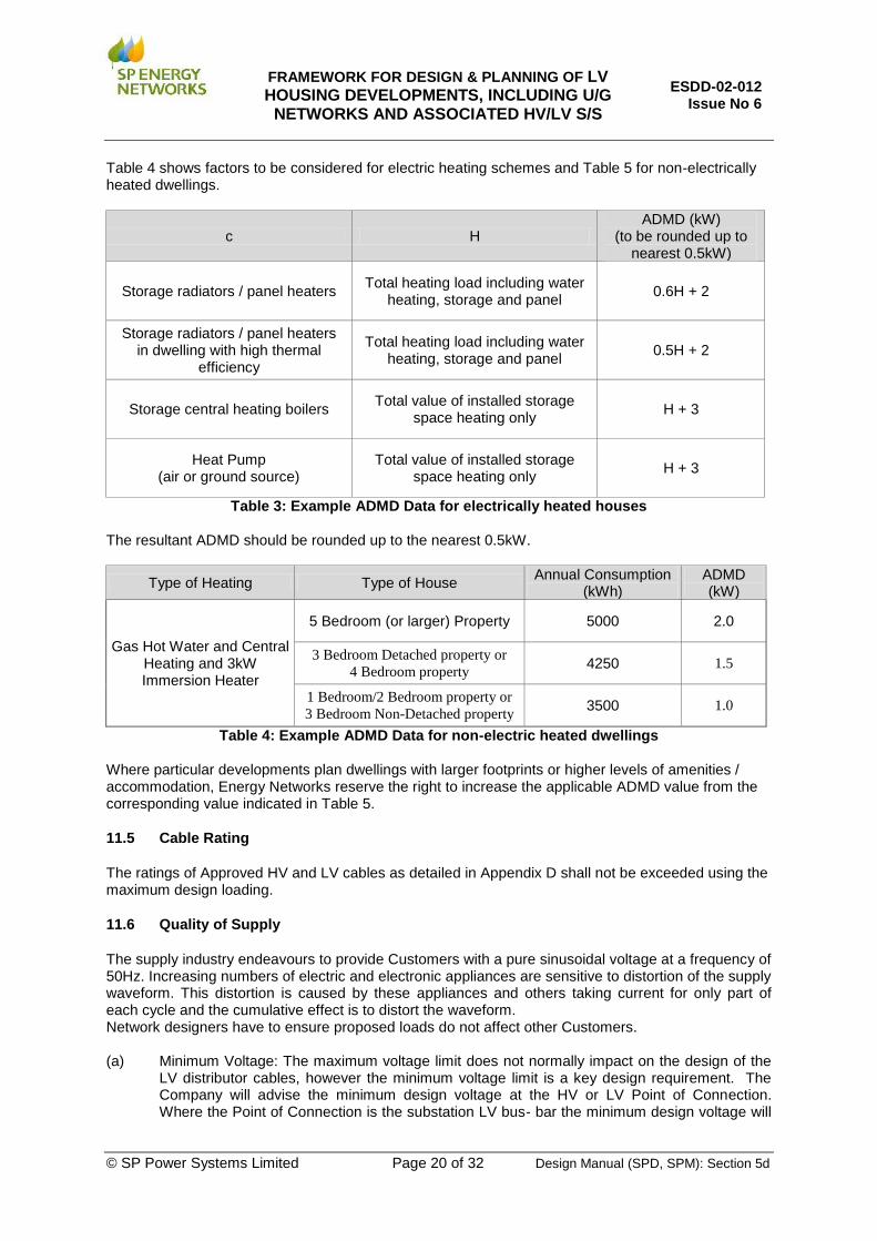
Table 4 shows factors to be considered for electric heating schemes and Table 5 for non-electrically heated dwellings.
c H ADMD (kW)
(to be rounded up to nearest 0.5kW)
Storage radiators / panel heaters Total heating load including water
heating, storage and panel 0.6H + 2
Storage radiators / panel heaters in dwelling with high thermal
efficiency
Total heating load including water heating, storage and panel
0.5H + 2
Storage central heating boilers Total value of installed storage
space heating only H + 3
Heat Pump (air or ground source)
Total value of installed storage space heating only
H + 3
Table 3: Example ADMD Data for electrically heated houses
The resultant ADMD should be rounded up to the nearest 0.5kW.
Type of Heating Type of House Annual Consumption
(kWh) ADMD (kW)
Gas Hot Water and Central Heating and 3kW Immersion Heater
5 Bedroom (or larger) Property 5000 2.0
3 Bedroom Detached property or
4 Bedroom property 4250 1.5
1 Bedroom/2 Bedroom property or
3 Bedroom Non-Detached property 3500 1.0
Table 4: Example ADMD Data for non-electric heated dwellings Where particular developments plan dwellings with larger footprints or higher levels of amenities / accommodation, Energy Networks reserve the right to increase the applicable ADMD value from the corresponding value indicated in Table 5.
11.5 Cable Rating
The ratings of Approved HV and LV cables as detailed in Appendix D shall not be exceeded using the maximum design loading.
11.6 Quality of Supply
The supply industry endeavours to provide Customers with a pure sinusoidal voltage at a frequency of 50Hz. Increasing numbers of electric and electronic appliances are sensitive to distortion of the supply waveform. This distortion is caused by these appliances and others taking current for only part of each cycle and the cumulative effect is to distort the waveform. Network designers have to ensure proposed loads do not affect other Customers. (a) Minimum Voltage: The maximum voltage limit does not normally impact on the design of the
LV distributor cables, however the minimum voltage limit is a key design requirement. The Company will advise the minimum design voltage at the HV or LV Point of Connection. Where the Point of Connection is the substation LV bus- bar the minimum design voltage will

FRAMEWORK FOR DESIGN & PLANNING OF LV HOUSING DEVELOPMENTS, INCLUDING U/G
NETWORKS AND ASSOCIATED HV/LV S/S
ESDD-02-012 Issue No 6
© SP Power Systems Limited Page 21 of 32 Design Manual (SPD, SPM): Section 5d
normally be +2.5% (235.75 V). The voltage limits will then be met with a maximum Mains cable and Service cable voltage drop of 8.5% (which would give a 6% drop on 230 V).The design of the new LV Mains cable shall ensure the 8.5% voltage drop limit is not exceeded with an overall maximum demand in accordance with the approved voltage drop calculation method (see below) whilst, simultaneously, any individual Service is subjected to its maximum rating. In addition, the maximum voltage drop from the substation LV bars to the most remote Service joint shall not exceed 5.5% under this design loading condition.
(b) Unbalanced Voltages: Unbalance of the magnitude of three phase voltages can occur due to unequal loading of the three phases. For example housing Services should be connected evenly over the three phases utilising R,Y,B,B,Y,R. Engineering Recommendation P29 gives further guidance on voltage imbalance.
(c) Rapid Voltage Change and rapid Voltage Fluctuations: Load switching, lifts, water or sewerage pumps or motor starting currents can cause rapid voltage change, similarly industrial loads such as welding plant can cause rapid voltage fluctuations. Applicants will have to demonstrate to Energy Networks that the principles in ER P28 have been applied to ensure disturbance to customers is kept to a minimum.
(d) dc Component: dc currents can be induced by semi-conductor devices installed in both domestic and industrial premises. Although no limiting value is set, it is recommended that in all instances the dc component should be reduced to a minimum.
(e) Harmonic Distortion: The flow of harmonic currents in the system causes distortion of the voltage waveform that can result in overheating of motors or cause malfunctioning of electronic equipment. Applicants will have to demonstrate to Energy Networks that the requirements detailed in Engineering Recommendation G5/4 are fully adhered to.
Applicants will have to demonstrate to Energy Networks that the proposed design meets all the quality of supply requirements detailed above.
11.7 Approved Voltage Drop Calculation Method
The total LV mains cable voltage drop shall be calculated by aggregating the voltage drops on each branch of an LV feeder, from the substation to the most remote point. The load assumed for each branch being given by the formula:
Design Load on Each Branch = Nb x ADMDw + 8 kW Where
Nb is the number of houses on the branch
ADMDw is the weighted average ADMD per house A copy of the voltage drop calculation, with a branch and node diagram cross-referenced to the proposed layout shall be presented as part of the design for approval.
11.8 Low Voltage Earthing and Bonding
New low voltage distribution systems will meet the requirements of the Electricity Safety, Quality and Continuity Regulations 2002. Part VII, Supplies to installations and other networks, Section 24, Equipment on consumer’s premises (4) states. ‘Unless he can reasonably conclude that it is inappropriate for reasons of safety, a distributor shall, when providing a new connection at low voltage, make available his supply neutral conductor, or if appropriate, the protective conductor of his network for connection to the protective conductor to the consumers installation.’ New single-occupied domestic premises shall be designed for protective multiple earthing. A PME earth terminal shall be made available at the Service termination where appropriate. It should be noted that there are situations where the Company will not provide an earth terminal.
FRAMEWORK FOR DESIGN & PLANNING OF LV HOUSING DEVELOPMENTS, INCLUDING U/G
NETWORKS AND ASSOCIATED HV/LV S/S
ESDD-02-012 Issue No 6
© SP Power Systems Limited Page 22 of 32 Design Manual (SPD, SPM): Section 5d
Full details of the Company’s earthing requirements can be obtained in guidance notes G12 and the EART-01-002 - Low Voltage Earthing Policy and Application Guide.
11.9 Short Circuit Currents
The maximum earth loop impedance and maximum short circuit fault level at each Service termination shall meet the requirements set out in Tables 2 & 3. Unless otherwise advised, the maximum design three phase short circuit currents at the relevant voltage levels on the Company’s network are:
35 kA (25 MVA) on the low voltage (400 V) system
13.1 kA (150 MVA) on the 6.6 kV system
13.1 kA (250 MVA) on the 11 kV system N.B. There may be points within the system where high network density or close proximity to a grid supply point / generating stations leads to higher fault levels than those stated above. In such cases equipment of suitable short circuit duty must be installed. HRC fuses at the substation protect low voltage mains cables. In order that the fuses shall operate to clear a fault at the most remote point on the LV main, the minimum phase to neutral short circuit current available shall be 3 times the substation fuse rating.

FRAMEWORK FOR DESIGN & PLANNING OF LV HOUSING DEVELOPMENTS, INCLUDING U/G
NETWORKS AND ASSOCIATED HV/LV S/S
ESDD-02-012 Issue No 6
© SP Power Systems Limited Page 23 of 32 Design Manual (SPD, SPM): Section 5d
12. DESIGN APPROVAL
Where the Company is to adopt the new distribution system, the proposed design shall be Approved by Energy Networks (allowing sufficient time for any revisions) before commencing on-site construction. Energy Networks have introduced an Internet based electronic registration and management system (C-RAM) to assist in the management of connection processes and documentation from application to completion. C-RAM enables electronic posting of all project documentation and full audit facilities to both Connectors and Energy Networks. Connectors wishing to use this system should contact Energy Networks Connections Business. In most cases the development of a full detailed design will be a two-stage process. The Applicant will submit an outline proposal (see Appendix A) providing sufficient detail to enable Energy Networks to indicate the most suitable Point of Connection to the network given the information provided. This will then enable the Applicant to undertake a full detailed design, which can be submitted to Energy Networks for approval as the final proposal see Appendix C. Having received this information Energy Networks will assess the design and prepare a formal quote for non-contestable works of the project. Where an applicant requires a firm quotation for non-contestable works prior to full design approval Energy Networks require the information in Appendix B. This will enable Energy Networks to issue Point of Connection to the network details and issue a formal quote for non-contestable works. For full design approval the information in Appendix C is still required. There are three possible options when the Company responds to the design; these are set out in Table 6.
Technical Requirements Additional Requirements Response
Proposed design does not comply with the requirements set-out in this document
- Not approved, with explanation.
Proposed design complies with the requirements set-out in this document
The Company does not require additional work
Approved
The Company requires additional work
Approved, subject to additional work being included.
Table 5: Design Approval
Only designs fully approved by the Company shall be constructed.

FRAMEWORK FOR DESIGN & PLANNING OF LV HOUSING DEVELOPMENTS, INCLUDING U/G
NETWORKS AND ASSOCIATED HV/LV S/S
ESDD-02-012 Issue No 6
© SP Power Systems Limited Page 24 of 32 Design Manual (SPD, SPM): Section 5d
APPENDIX A – MINIMUM INFORMATION TEMPLATE FOR INDICATIVE CONNECTION COST
In order to generate an indicative Cost of Connection of New Housing Development the following minimum information will be required:
Location Plan Including OS map reference, of a suitable size and scale (normally 1:2500 or 1:1250) to allow the location of the proposed development against other surrounding features.
Number of houses
Phasing of development and initial connection date of each phase
Heating type E.g. gas/oil/storage heating/electric, etc.
Estimated individual demand
Estimated total peak demand for the development
Site layout plan If available.
Where known details of future new related developments
Applicants suggested / proposed connection point

FRAMEWORK FOR DESIGN & PLANNING OF LV HOUSING DEVELOPMENTS, INCLUDING U/G
NETWORKS AND ASSOCIATED HV/LV S/S
ESDD-02-012 Issue No 6
© SP Power Systems Limited Page 25 of 32 Design Manual (SPD, SPM): Section 5d
APPENDIX B - MINIMUM INFORMATION TEMPLATE FOR QUOTATION
Quotation request for connection of Low Voltage Housing Estates Installations & Associated HV / LV Distribution Substations Please note the following:
This template does not relate to multi-occupied premises, which are covered separately.
Although Appendix A will allow an indicative cost for outline design purposes to be generated, the more detailed information specified in Appendix B will enable an accurate design to be undertaken by the Company. In some cases this may differ in cost from the original outline design quotation. To avoid / minimise such differences, it is strongly recommended that Appendix B information be provided in conjunction with the initial enquiry.
Main Area Component details
Applicant(s) Name, address, contact details
Contractor(s) – indicating their NERS accreditation as detailed in Energy Networks New Connection Contractor Approval Policy ASSET-01-015
Landowner
Solicitor of Landowner
Architect/Consultant
Location / environment Location/postal address/OS map reference.
Known details of future new related developments.
Overall size/type of development
Total number of properties.
Number by type of housing/mix (no. of bedrooms, house/flat type etc) and any issues relating to supply security e.g. sheltered housing, etc.
Heating type (space/water).
Phasing Phase(s) of development.
Initial connection date of each phase.
Estimated completion date of each phase.
Connection Suggested/proposed connection point.
Landlords connection(s) required.
Demand Estimated individual dwelling demand including individual maximum power requirements kVA or kW per property, ADMD per property (with supporting evidence) and details relating to type and electrical loading of equipment to be connected. For example, the number and size of motors, cookers, showers, space and water heating arrangements including details of equipment which is subject to switching by the Supplier (e.g. white meter, economy 7 or option heating schemes).
Estimated total site demand.
Estimated electric space heating load (off/on peak).
Associated street lighting (nos.) Un-metered supplies should be highlighted with classes and maximum demands.

FRAMEWORK FOR DESIGN & PLANNING OF LV HOUSING DEVELOPMENTS, INCLUDING U/G
NETWORKS AND ASSOCIATED HV/LV S/S
ESDD-02-012 Issue No 6
© SP Power Systems Limited Page 26 of 32 Design Manual (SPD, SPM): Section 5d
APPENDIX C - MINIMUM INFORMATION TEMPLATE FOR DESIGN APPROVAL AND QUOTATION
Quotation request for connection and design approval of Low Voltage Housing Estates Installations & Associated HV / LV Distribution Substations Please note the following:
This template does not relate to multi-occupied premises, which are covered separately.
Although Appendix A will allow an indicative cost for outline design purposes to be generated, the more detailed information specified in Appendix C will enable an accurate design to be undertaken by the Company. In some cases this may differ in cost from the original outline design quotation. To avoid / minimise such differences, it is strongly recommended that Appendix B information be provided in conjunction with the initial enquiry.
Energy Networks can respond to a request for design approval in three ways: Not Approved. Explanation given by Energy Networks; Approved, or: Approved subject to additional work being included.
Main Area Component details
Applicant(s) Name, address, contact details
Contractor(s) – indicating their NERS accreditation as detailed in Energy Networks New Connection Contractor Approval Policy ASSET-01-015
Landowner
Solicitor of Landowner
Architect/Consultant
Location/environment Location/postal address/OS map reference.
Known details of future new related developments.
Overall size/type of development
Total number of properties.
Number by type of housing/mix (no. of bedrooms, house/flat type etc) and any issues relating to supply security e.g. sheltered housing, etc.
Heating type (space/water).
Phasing Phase(s) of development.
Initial connection date of each phase.
Estimated completion date of each phase.
Connection Suggested/proposed connection point.
Landlord’s connection(s) required.
Demand Estimated individual dwelling demand including individual maximum power requirements kVA or kW per property, ADMD per property (with supporting evidence) and details relating to type and electrical loading of equipment to be connected. For example, the number and size of motors, cookers, showers, space and water heating arrangements including details of equipment which is subject to switching by the Supplier (e.g. white meter, economy 7 or option heating schemes).
Estimated total site demand.
Estimated electric space heating load (off/on peak).
Associated street lighting (nos.) Un-metered supplies should be highlighted with classes and maximum demands.
Details/drawings 2 copies of a site location plan of suitable size and scale (1:2500 or 1:1250 as appropriate) to indicate location of development against other surrounding features.
2 copies of a layout drawing on 1:500 scale plan(s) showing the layout and details such as cable sizes, etc of all proposed electrical apparatus shown against the new roads and housing proposal. Details of proposed substation locations, adopted areas and meter positions shall also be marked. The phase (red, yellow or blue) that each Service is to be connected must be shown.
FRAMEWORK FOR DESIGN & PLANNING OF LV HOUSING DEVELOPMENTS, INCLUDING U/G
NETWORKS AND ASSOCIATED HV/LV S/S
ESDD-02-012 Issue No 6
© SP Power Systems Limited Page 27 of 32 Design Manual (SPD, SPM): Section 5d
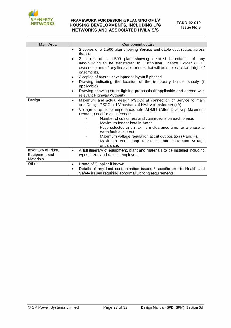
Main Area Component details
2 copies of a 1:500 plan showing Service and cable duct routes across the site.
2 copies of a 1:500 plan showing detailed boundaries of any land/building to be transferred to Distribution Licence Holder (DLH) ownership and of any line/cable routes that will be subject to land-rights / easements.
2 copies of overall development layout if phased.
Drawing indicating the location of the temporary builder supply (if applicable).
Drawing showing street lighting proposals (if applicable and agreed with relevant Highway Authority).
Design Maximum and actual design PSCCs at connection of Service to main and Design PSCC at LV busbars of HV/LV transformer (kA).
Voltage drop, loop impedance, site ADMD (After Diversity Maximum Demand) and for each feeder:
- Number of customers and connections on each phase. - Maximum feeder load in Amps. - Fuse selected and maximum clearance time for a phase to
earth fault at cut out. - Maximum voltage regulation at cut out position (+ and –). - Maximum earth loop resistance and maximum voltage
unbalance.
Inventory of Plant, Equipment and Materials
A full itinerary of equipment, plant and materials to be installed including types, sizes and ratings employed.
Other Name of Supplier if known.
Details of any land contamination issues / specific on-site Health and Safety issues requiring abnormal working requirements.

FRAMEWORK FOR DESIGN & PLANNING OF LV HOUSING DEVELOPMENTS, INCLUDING U/G
NETWORKS AND ASSOCIATED HV/LV S/S
ESDD-02-012 Issue No 6
© SP Power Systems Limited Page 28 of 32 Design Manual (SPD, SPM): Section 5d
APPENDIX D - CABLE ELECTRICAL & RATING DATA
Conductor CSA
(sqmm)
Cyclic Rating Factor
Cable Ratings (Amps)* Cable Impedance Data (Ohms/km) Capacitance
(uF/km) Laid Direct Ducted Max DC resistance per
phase @ 20 degC Max AC resistance per
phase @ 65 degC & 50Hz Reactance @
50Hz Continuous Cyclic Continuous Cyclic
95 1.11 189 215 157 173 0.320 0.413 0.110 0.290
185 1.12 273 315 236 257 0.164 0.215 0.086 0.370
300 1.12 357 420 310 341 0.100 0.133 0.071 0.450
Derating factors for groups of cables** * Ratings are based on the following conditions (single core cables
laid in trefoil and bonded at both ends)
No of Cables Derating factor Depth of cover (m) 0.6
1 1.00 Ambient ground temperature (degC) 15
2 0.89 Soil thermal resistivity (degKm/W) 1.2
3 0.80
4 0.77
** Based on spacing between cables = 300mm

FRAMEWORK FOR DESIGN & PLANNING OF LV HOUSING DEVELOPMENTS, INCLUDING U/G
NETWORKS AND ASSOCIATED HV/LV S/S
ESDD-02-012 Issue No 6
© SP Power Systems Limited Page 29 of 32 Design Manual (SPD, SPM): Section 5d
Cable Electrical & Rating Data for 11kV 3-Core XLPE cable
Conductor CSA
(sqmm)
Cyclic Rating Factor
Cable Ratings (Amps)* Cable Impedance Data (Ohms/km) Capacitance
(uF/km) Laid Direct Ducted Max DC resistance per
phase @ 20 degC Max AC resistance per
phase @ 65 degC & 50Hz Reactance @
50Hz Continuous Cyclic Continuous Cyclic
95 1.11 189 215 157 173 0.320 0.408 0.099 0.310
185 1.12 273 315 236 257 0.164 0.210 0.088 0.420
300 1.12 357 420 310 341 0.100 0.129 0.082 0.480
Derating factors for groups of cables** * Ratings are based on the following conditions (single core cables
laid in trefoil and bonded at both ends)
No of Cables Derating factor Depth of cover (m) 0.6
1 1.00 Ambient ground temperature (degC) 15
2 0.89 Soil thermal resistivity (degKm/W) 1.2
3 0.80
4 0.77
** Based on spacing between cables = 300mm

FRAMEWORK FOR DESIGN & PLANNING OF LV HOUSING DEVELOPMENTS, INCLUDING U/G
NETWORKS AND ASSOCIATED HV/LV S/S
ESDD-02-012 Issue No 6
© SP Power Systems Limited Page 30 of 32 Design Manual (SPD, SPM): Section 5d
Cable Electrical & Rating Data for 11kV PICAS cable
Conductor CSA
(sqmm)
Cyclic Rating Factor
Cable Ratings (Amps)* Cable Impedance Data (Ohms/km) Capacitance (uF/km) Laid Direct Ducted Max DC resistance per
phase @ 20 degC Max AC resistance per
phase @ 65 degC & 50Hz Reactance @
50Hz Continuous Cyclic Continuous Cyclic
95 1.11 185 205 160 177 0.320 0.379 0.087 0.450
185 1.12 270 302 230 258 0.164 0.195 0.080 0.580
300 1.12 355 408 305 351 0.100 0.120 0.077 0.710
Derating factors for groups of cables** * Ratings are based on the following conditions (single core cables laid in trefoil and bonded at both ends)
No of Cables Derating factor Depth of cover (m) 0.6
1 1.00 Ambient ground temperature (degC) 15
2 0.89 Soil thermal resistivity (degKm/W) 1.2
3 0.80
4 0.77
** Based on spacing between cables = 300mm

FRAMEWORK FOR DESIGN & PLANNING OF LV HOUSING DEVELOPMENTS, INCLUDING U/G
NETWORKS AND ASSOCIATED HV/LV S/S
ESDD-02-012 Issue No 6
© SP Power Systems Limited Page 31 of 32 Design Manual (SPD, SPM): Section 5d
Cable Electrical & Rating Data for 3-core Waveform cable
Conductor CSA
(sqmm)
Cyclic Rating Factor
Cable Ratings (Amps)* Cable Impedance Data (Ohms/km)
Laid Direct Ducted Max DC resistance per
phase @ 20 degC
Max DC resistance of neutral/earth @ 20
degC
Max AC resistance per phase @ 80 degC /
50Hz
Reactance @ 50Hz Continuous Cyclic Continuous Cyclic
95 1.15 192 240 154 209 0.320 0.320 0.398 0.0735
185 1.24 332 416 269 310 0.164 0.164 0.205 0.0740
300 1.28 436 546 356 410 0.100 0.164 0.126 0.0725
Derating factors for groups of cables** * Ratings are based on the following conditions (single core cables
laid in trefoil and bonded at both ends)
No of Cables Derating factor Depth of cover (m) 0.45
1 1.00 Ambient ground temperature (degC) 15
2 0.90 Soil thermal resistivity (degKm/W) 1.2
3 0.82
4 0.78
** Based on spacing between cables = 250mm

FRAMEWORK FOR DESIGN & PLANNING OF LV HOUSING DEVELOPMENTS, INCLUDING U/G
NETWORKS AND ASSOCIATED HV/LV S/S
ESDD-02-012 Issue No 6
© SP Power Systems Limited Page 32 of 32 Design Manual (SPD, SPM): Section 5d
Cable Electrical & Rating Data for LV CNE Service cable
Phases
Conductor CSA (sqmm)
Conductor material
Cable Ratings (Amps)* Cable Impedance Data (Ohms/km)
Laid Direct
Ducted In Air Max DC resistance per
phase @ 20 degC
Max DC resistance of neutral/earth @ 20
degC
Max AC resistance per phase @ 80 degC /
50Hz
Reactance @ 50Hz
1 4 Cu 55 53 45 4.61 4.8 5.4
1 25 Al 120 116 97 1.2 1.3 1.42 1.45
1 35 Al 146 140 120 0.868 0.91 1.02 1.05
3 25 Al 101 97 84 1.2 1.3 1.42
3 35 Al 120 115 100 0.868 0.91 1.02
* Ratings are based on the following conditions
Depth of cover (m) 0.45
Ambient ground temperature (degC) 15
Soil thermal resistivity (degKm/W) 1.2