frank kyei-manu aloysius obodoako advisor: professor e
TRANSCRIPT

Frank Kyei-Manu Aloysius Obodoako
Advisor: Professor E. Carr Everbach
November 29 2005
Solar Stirling-Engine Water Pump Proposal Draft
The goal of this project is to design, build and instrument a Solar Stirling-engine Water Pump using fluidyne technology and to evaluate its performance. The motivation behind the project is the recently revived interest in the liquid-piston Stirling engines as an alternative power source. The objectives of the project will be (1) to build an engine with a power output of at least 5W capable of pumping water to a height of at least 7 feet; (2) to generate P-V diagrams of the engine’s performance in real-time; (3) to investigate engine performance with different fluid types, manometer diameters, manometer lengths, among others and (4) To boil the water that has been pumped using focused sunlight. A suitable design will be selected for power output, mechanical simplicity and sustainability. The engine will be built for the pedagogical purpose of demonstrating fluidyne technology principles in a laboratory setting. Other applications to be investigated will be solar-power generation and use as a heat pump. The project will involve significant machine shop work and software modeling.
1

TABLE OF CONTENTS: 1.0 Introduction…………………………………………………………1 2.0 Technical Discussion
2.1 Basic operation of a generic stirling engine………………...3-4 2.2 The liquid piston fluidyne engine…………………………. .5 2.3 Tuning of Liquid Columns………………………………….5 2.4 Pumping Configurations……………………………………6 2.5 Effects of Evaporation and Mean Pressure………………....6 2.6 Basic Design and Power Calculations………………………7-9
3.0 Design Considerations 3.1 Mechanical Analysis………………………………………..9 3.2 Fluid Choice…………………………………………………9 3.3 Trade-offs among alternatives………………………………9 3.4 Shop Work…………………………………………………..9 3.5 Instrumentation……………………………………………..10 3.6 Heat Source…………………………………………………10 3.7 Isothermalizers……………………………………………...10 3.8 Regenerator………………………………………………….10 3.9 Self-Starting System…………………………………………10 3.10 Actual Designs…………………………………………...10-13
4.0 Project Qualifications………………………………………………...13 5.0 Project Cost…………………………………………………………..13 6.0 Project Plan…………………………………………………………...14 7.0 Reference……………………………………………………………...15
2

1.0 Introduction There is an ongoing campaign for the need for alternative energy sources to meet demands of today’s world. The abundance of solar energy especially in sub-Saharan African is a fact that cannot be overlooked. This ever-present energy source is however underutilized despite the many uses to which it can be put. It is with this in mind that Aloysius Obodoako and Frank Kyei-Manu intend to address one of the pressing needs in developing countries. Residents in developing countries often cannot count on the availability of clean drinking water due to the pollution of surface water sources such as rivers and lakes. Thousands of deaths occur every year from water-borne diseases alone. In countries with plentiful sunlight, heat energy powered by a constant supply of solar energy could be used to pump well water. In addition, the water that is pumped could be boiled by the same focused sunlight, thereby providing a continuous source of clean water. The purpose of this project is to design and implement a liquid piston Stirling engine that outputs enough power to pump water from a depth of at least 6 feet [ask about minimum power required]. We also intend to include a parabolic collecting mirror that will focus the sun’s energy to heat the system. The system we plan to implement will use fluidyne technology, which is currently underappreciated. The remainder of this proposal provides detailed discussion of this project and is organized into the following sections: Technical Discussion, Project Plan (Include Critical Path Method), Project Qualifications and Project Cost. The technical discussion highlights the tools and technology that is required to develop and build the liquid piston stirling engine; the project plan presents the tasks to be accomplished and the timeframe within which to complete them; the qualifications section discussed the reasons why we are qualified to do this project and finally the project cost section will present the project budget. 2.0 Technical Discussion 2.1 Basic Operation of a generic Stirling Engine The basic principle of the Stirling engine is a simple one: it relies only on the fact that when a gas is heated, it tends to expand or, if confined, to a rise in pressure. The Stirling cycle, which is an idealized thermodynamic cycle consists of two isothermal and two constant-volume cycles. There are currently three configurations of the Stirling engines – alpha, beta and gamma – available in the market. Our choice will depend on the power output we expect as well as on efficiency. Stirling engines work by the repeated heating and cooling of a sealed amount of working gas which in our case will be air. The gas follows the behaviour described by the gas laws which describe how a gas’ pressure, temperature and volume are related. When the gas is heated, because it is in a sealed chamber, the pressure rises and this then acts on the power piston to produce a power stroke. When the gas is cooled, the pressure drops and this means that less work needs to be done by the piston to recompress the gas on the
3

return stroke, giving a net gain in power available on the shaft. The working gas flows cyclically between the hot and cold heat exchangers. Fig 1 below shows how the displacer pressure changes can be used to drive another piston to do work. The cylinder and piston on the right hand side are often called the expansion cylinder and power piston. When the displacer piston is at the hot end, the power piston is returned to its original position. Some work is needed to do this, but it is less than the work which was made available when the power piston moved out, because the force on this piston is now less, owing to the reduced gas pressure. Thus, over the complete cycle, more energy can be taken out of the power piston than needs to be put in; and this excess of energy can be used to operate the pump or to perform any of the other duties expected of an engine.
4

2.2. The Liquid Piston Fluidyne Engine The liquid piston Stirling operates quite differently from the generic Stirling engine described above. The most obvious is the fact that the mechanical pistons are replaced by water. Therefore, as the hot side is heated, the increased air pressure raises water on the cold side and lowers water on the hot side. This creates a pressure which moves the water out one valve way. Once the air has expanded to its maximum point a pressure drop takes place and the water on the hot side rises and the cold side lowers. Also, the other valve opens and replaces the water. The advantage of this system is that it will run on a fairly low temperature but of course, will pump a lot of water the hotter it gets.
Fig 2: Basic schematic of a fluidyne
The most important factor in Stirling engine design is the efficiency losses due to non-idealities. Due to imperfections, the efficiencies of Stirling engines are significantly lower than the ideal ones. The non-idealities include adiabatic losses and heat losses from mechanical components. 2.3 Tuning of Liquid Columns As in any oscillating system, the maximum amplitude of movement in the output column will be achieved if the frequency of the pressure variation, ie, the driving force upon it, is about equal to the natural or resonant frequency of the water oscillating in the output column. These pressure variations are due to the oscillations of the displacer water, so it follows that for maximum movement, we must make the two natural frequencies equal. If the water column length in the output tube is too long, the mass of water in it will be so great that the pressure change will be unable to move it very far and hence almost no work will be done. On the other hand, if the water column is too short, it will move so easily that the pressure in the engine will be unable to build up significantly before the column moves to its full extent, and again almost no work will be done. The length of the output tube must therefore be tuned to suit the operating frequency of the engine. 2.4 Pumping Configuration
5
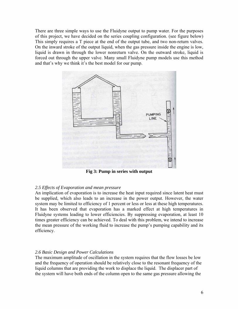
There are three simple ways to use the Fluidyne output to pump water. For the purposes of this project, we have decided on the series coupling configuration. (see figure below) This simply requires a T piece at the end of the output tube, and two non-return valves. On the inward stroke of the output liquid, when the gas pressure inside the engine is low, liquid is drawn in through the lower nonreturn valve. On the outward stroke, liquid is forced out through the upper valve. Many small Fluidyne pump models use this method and that’s why we think it’s the best model for our pump.
Fig 3: Pump in series with output
2.5 Effects of Evaporation and mean pressure An implication of evaporation is to increase the heat input required since latent heat must be supplied, which also leads to an increase in the power output. However, the water system may be limited to efficiency of 1 percent or less or less at these high temperatures. It has been observed that evaporation has a marked effect at high temperatures in Fluidyne systems leading to lower efficiencies. By suppressing evaporation, at least 10 times greater efficiency can be achieved. To deal with this problem, we intend to increase the mean pressure of the working fluid to increase the pump’s pumping capability and its efficiency. 2.6 Basic Design and Power Calculations The maximum amplitude of oscillation in the system requires that the flow losses be low and the frequency of operation should be relatively close to the resonant frequency of the liquid columns that are providing the work to displace the liquid. The displacer part of the system will have both ends of the column open to the same gas pressure allowing the
6

effects of pressure to cancel out. The liquid stirling engine configuration that closely matches the system which we propose to build and provides similar system parameters is the tuning-column configuration with connecting cylinders, figure 5.
The oscillation would start by one end of the displacer arm will rising slightly by a distance χ, the hot and cold parts of the displacer will accomplish this, and because the liquid level in one arm rises the liquid level in the other end of the displacer will necessarily fall by the same distance χ, see figure 4.
Figure 4: Simple Displacer U-tube
One end of the column has more weight of the liquid by an amount 2χAdρ. In addition, the pressure brought about due to the increased weight of the liquid is 2χρg and the resulting force is 2Adχρg. Furthermore, the mass of the liquid column is AdρLd, consequently; the acceleration induced by this force in the direction to reduce χ is given by equation 1, below:
2d D dA L A gρ χ χ ρ= − (1.1) 2
D
gxL
χ −= (1.2)
Equation 1 and 2 are parameters for the undamped simple harmonic motion. This acceleration corresponds to the natural frequency ω in equation 2, below:
2
D
gL
ω = rad/s (2.1)
or 1 22 D
gfLπ
= Hz (2.2)
7

The tuning-column also has a corresponding natural frequency with the displacer. Deriving the natural frequency of the tuning-column is more difficult to derive because the force caused by compression, or expansion, of the gas above the liquid in the engine are not canceled out when acting on both ends of the liquid column, as they would be in the displacer, see figure 5.
Figure 5: Merged-cylinder, the U-tube and the tuning column
When the liquid in the open end is displaced a distance χ two things occur. Firstly, the liquid at the other end is raised by an amount χ, and secondly, the volume of the gas in the working space is reduced by an amount Atχ. These two effects cause a pressure difference across the tuning column tending to force it back toward the steady-state position. For an ideal stirling engine the gas space is isothermal and is initially at a pressure Pm. The pressure will rise by an amount p, given in equation 3, below:
t m
m
A P xpV
= (3)
where p is amount the pressure will rise in the machine and is usually smaller than Pm. The pressure difference between the liquid surface in the displacer and in the open end of the tuning column can be viewed in equation 4, below:
( 1) ( 2) ( 3)2
m t t
m d
P A x gxAP part part gx partV A
ρρΔ = + + (4)
where parts 1, 2 and 3 of the equation represent the values of pressure from the gas compression, tuning liquid level lowered and the displacer liquid level raised, respectively. Using equation 4, the natural frequency can be derived by dividing the entire equation by ρgχLt and taking the square root of the final value, see equation 5, below:
[1 / 2 ]t m t d
m t t
A P A AV L L
ωρ
+= +
g rad/s (5.1)
8

or [1 / 2 ]12
t m t d
m t t
A P A AfV L Lπ ρ
+= +
g Hz (5.2)
2.7 Power Output The power output of the system will be calculated using a simplified expression, based on Cooke-Yarborough’s expression, with separate displacer and tuning column cylinders. The expression can be found in equation 6, below:
sin4
e e co m o
m e c
V T TW P V fV T T
π θ−=
+ (6.0)
were the volumes are Vo, Ve, Vm, which represent the volume swept out by the surface of the tuning column, volume swept out by either surface of the displacer, and the midstroke volume, respectively. The temperatures of the hot and cold spaces are Te and Tc, respectively. The mean pressure, phase angle between the displacer and tuning column and the frequency of operation are represented by Pm, θ, and f. 3.0 Design Considerations 3.1 Mechanical Analysis We will develop a model that will include thermal stress analysis of so as to optimize the transfer of heat between the external source as the fluid within, among others. A simple modeling in a program such as ANSYS will enable us get a better sense of the thermal stress capabilities of our components.
3.2 Fluid Choice Even though at the onset it seems water will be the working fluid in our system, we intend to consider other possibilities and take into account such factors as specific heat capacities, flammability, density, etc in deciding the fluid type to use.
3.3 Trade-offs among alternatives We will also perform comparative analysis among the different possibilities. We will examine factors such as efficiencies, power output, complexity vs simplicity in design as well as costs. The goal at the end of the day is to have a working system the produces enough power with as high efficiency as possible. 3.4 Shop work Making components; the expansion and compression spaces, regenerator, etc. 3.5 Instrumentation An essential part of the project will be the addition of sensors for pressure, temperature and volume. The sensors will provide information on the engine and will be used in obtaining experimental P-V and other diagrams. To measure pressure, a pressure transducer will be used, thermocouples for temperature and some volume measurement device.
9

3.6 Heat Source We would also have to consider a choice between a photovoltaic, a parabolic solar collector and direct solar heating. Again our decision will be based on the energy conversion capabilities of these competing systems. Our initial assessment seems to favors using solar collector panels because photovoltaic will convert the solar energy into electricity, which is not always available. 3.7 Isothermalizers The cold cylinder will be subdivided into gaps of no more than several cylinders in order to get good heat transfer. This will also be applied to the hot end of the machine given that no evaporation will be permitted. To achieve the subdivision in the cold cylinder, aluminium sheet will be folded into a concertina shape and fixed inside the cylinder. The effect of this subdivision will be to make the gas in the cylinder behave more or less isothermally. 3.8 Regenerator Regenerators are also important in Fluidynes in order to achieve high efficiency. At low temperatures, drinking straws will be used as a regenerator, and at high temperatures, metal tubes will be used. 3.9 Self-Starting System This Liquid piston Fluidyne engine will be designed to self-start when the temperature is raised beyond a certain threshold; ie the liquid will begin oscillating of its own accord. However, there might be the need to manually rock the engine to get it started. 3.10 Practical Design 1 The structure of the fluidyne system will be composed of glass. Ideally, the type of glass used to build the structure will be Borosilicate glass. This glass type can withstand high temperatures and high-temperature gradients. In addition, it is not permeable to water or air and it is transparent. The liquid fluidyne engine which we propose to build will be modeled after David Herbert’s stirling pump and engine system. This system can easily be constructed to be solar-powered using an inexpensive plastic Fresnel lens. The best results for this system are usually obtained if the sunlight is focused onto the hot cylinder at approximately the mean water level. The amount of heat absorbed by the hot end of the machine can be increased by placing a reflector at the back of the cylinder, or by blackening one of the surfaces. Please see fig. 6 overleaf.
10

Fig 6. Glass fluidyne pump Practical Design 2 A second design which we will consider to base our fluidyne stirling system on is called the Fruit Jar Machine. This design is based upon a fruit jar like container. The pump uses ball bearings or glass beads as ball valves. The U tube used in the machine may need to be constructed or fabricated by a glass blowing shop. Please see fig 6.
11

Fig 6: Fruit-Jar Machine
12

The machine is easily maintained and operates without critical adjustments as a free running engine; the pump is disconnected. The dimensions of the cylinders and the length of the tuning line inserted into the hot cylinder may require careful adjustment to achieve successful operations with the pump series-coupled. Because the pump is disconnected it may be adjusted to fit the series-coupled or parallel configuration. Providing heat to the engine may be achieved by several methods. Our primary goal for this project is to utilize solar energy to provide heat for system operation. This pay be achieved by using solar panels and or using a focusing device, if that latter proves achieve our goals solar panels may not be implemented. 4.0 Project Qualifications As senior engineering students at Swarthmore College, we have taken and participated in many relevant courses, projects, and labs that would help in developing unique methods in achieving the goal of creating a Fluidyne Stirling Engine water pump. Collectively, we have the taken the courses E41 which would assist in our understanding of the fluid dynamics of the system. In addition, Aloysius will have completed E83 and would be able to further contribute acquired knowledge in dealing with fluid flow. Furthermore, Frank and Aloysius have taken E14 and E35, respectively, and would be able to provide essential methods of designing the experiment to test the system and the latter course will afford the team to have some background knowledge on solar energy systems. Additionally, we have acquired significant experience with various computer software programs such as MatLab, AutoCad, and Multisim. The programs mentioned may not all be used during this project, but familiarity with the programs would assist in allowing us to gage what type of software programming may be useful and/or necessary. In addition, we have the potential to coordinate with other programs that are working on similar project and others that have completed work on similar systems. The knowledge that the Swarthmore Engineering department possess would likewise be used as a resource in creating the stirling engine water pump. 5.0 Project Costs
The estimated costs for this project will mainly depend on the materials needed to build the fluidyne stirling engine. Because photovoltaic panels and the software needed to design the system can be found at Swarthmore the only expenses will be the components to the stirling engine, a device used to focus solar energy, and additional solar collector components for the photovoltaic panels.
• Components for Stirling Engine $100 • Focus Device $ 20 • Photovoltaic Panel Components $ 50
---------- $170
13
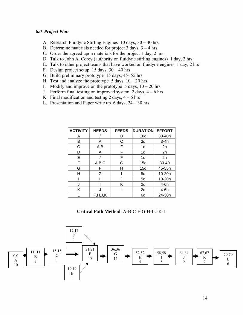
6.0 Project Plan A. Research Fluidyne Stirling Engines 10 days, 30 – 40 hrs B. Determine materials needed for project 3 days, 3 – 4 hrs C. Order the agreed upon materials for the project 1 day, 2 hrs D. Talk to John A. Corey (authority on fluidyne stirling engines) 1 day, 2 hrs E. Talk to other project teams that have worked on fluidyne engines 1 day, 2 hrs F. Design project setup 15 days, 30 – 40 hrs G. Build preliminary prototype 15 days, 45- 55 hrs H. Test and analyze the prototype 5 days, 10 – 20 hrs I. Modify and improve on the prototype 5 days, 10 – 20 hrs J. Perform final testing on improved system 2 days, 4 – 6 hrs K. Final modification and testing 2 days, 4 – 6 hrs L. Presentation and Paper write up 6 days, 24 – 30 hrs
ACTIVITY NEEDS FEEDS DURATION EFFORT
A / B 10d 30-40h B A C 3d 3-4h C A,B F 1d 2h D A F 1d 2h E / F 1d 2h F A,B,C G 15d 30-40 G F H 15d 45-55h H G I 5d 10-20h I H J 5d 10-20h J I K 2d 4-6h K J L 2d 4-6h L F,H,J,K 6d 24-30h
Critical Path Method: A-B-C-F-G-H-I-J-K-L
17,17 D 1
19,19 E 1
21,21 F 15
36,36G 15
52,52H 5
58,58I 5
64,64 J 2
67,67K 2
70,70 L 6
11, 11 B 3
0,0 A 10
15,15 C 1
14
7.0 REFERENCE: West, C.D. 1983. Liquid Piston Stirling Engines. Van Nostrnad Reinhold Publishing.
15