frauscher axle counting system acs2000
Post on 11-Sep-2014
2.331 views
DESCRIPTION
Frauscher Sensor Technology Frauscher Sensortechnik GmbH is the leading provider of technology for inductive sensors in the rail sector. Since 1986, Frauscher has been developing, producing and supplying inductive sensor technology, wheel detection and axle counting systems for an extremely wide range of applications. As an independent, medium-sized company, we place particular value on permanent innovation, maximum quality and above-average customer focus. A full range of services includes both individual planning and design as well as installation and start-up support. A comprehensive training programme ensures that operators are able to install the systems independently, operate them on a long-term basis, maintain them and even configure them where necessary. This guarantees maximum independence from the system supplier and minimal life cycle costs.TRANSCRIPT

www.frauscher.com
Axle Counting System ACS2000 >
Modular System for Efficient Track Vacancy Detection
DB
AG
/Bed
esch
insk
i

0� www.frauscher.com
Rationalisation of railway traffic and improvement of transport services require modern technology in many areas of railway operations.
In regard to track protection this translates into automatic track vacancy detection systems, which decisively improve safety - the prerequisite to increase efficiency.
For years, modern axle counting systems have been supplanting the formerly widespread track circuits as automatic track vacancy detection systems. The reliability and economic efficiency of modern axle counting systems as well as their independence from the track superstructure afford railways with considerable rationalisation potential.
As a manufacturer of components and specialist for inductive sensor technology, Frauscher has been supplying axle counting systems of type AZF (Axle Counting System Frauscher), which are currently being used in large numbers by many railway operators.
The ACS2000 Axle Counting System was developed based on this experience. Compared with the proven predecessor system AZF, additional functions, e.g. signalling safe data transmission between two axle counting boards, were integrated and its economic efficiency increased yet once more. Furthermore, due to its modular architecture, it is possible to configure application-specific systems, which allow for optimal consideration of the client‘s operating conditions. Application of CENELEC development standards ensure high quality and safety. The system can be configured for light rail and industrial railways as well as for high-performance lines running long-distance trains for passenger transport.
The implementation of easy and open interfaces provides for an easy-to-operate and reliable axle counting system that can be applied universally and proprietor-free for track vacancy detection tasks.
Responsibility through Safety.

0�
Modular Design of the SystemThe Axle Counting System ACS�000 comprises counting heads at the track, the
trackside equipment and the indoor installation with the axle counting system.
Depending on client requirements three different types of wheel sensors are available for axle counting using the ACS2000 system.
Wheel sensors RSR122 and RSR123 comprise two independent wheel sensor systems, separated by galvanic coupling, arranged longitudinally in the wheel sensor housing, which detect the wheel flange of the train wheel. The eddy current and hysteresis method used by RSR122 is based on the fact that an electromagnetic alternating field will lose energy when damped by metal (wheel flange, rail).
The newly developed RSR123 wheel sensor uses the so-called V.Mix technology®, which combines three operating principles, namely the eddy current and hysteresis method, the deflection of field lines and the inductivity method. As a result the RSR123 wheel sensor is immune to the electromagnetic loads, which nowadays affect railway tracks and beyond. This has been demonstrated conclusively by many tests.
Both RSR122 and RSR123 wheel sensors are immune to the cadenced, linear eddy current brakes and are therefore, especially suitable for lines where vehicles using this type of brake are operated.
Trackside Equipment
Wheel sensor RSR122 Wheel sensor RSR123 Wheel sensor RSR180
The proven RSR180 wheel sensor comprises two wheel sensor systems, arranged in the wheel sensor
housing in parallel with the rail at a distance of 180 mm. The operating principle is based on the deflection
of field lines. Due to its position-tolerant mounting at the rail and the absence of electrical adjustments at
the rail, this wheel sensor is suitable for all conventional applications.
All wheel sensors share the following features: > quick and precise mounting at the inner face of the rail using rail claw mounting,> total absence of electronic components in the proximity of the track,> no expensive test and measurement devices,> no system maintenance requirement in the dangerous track area.
0�
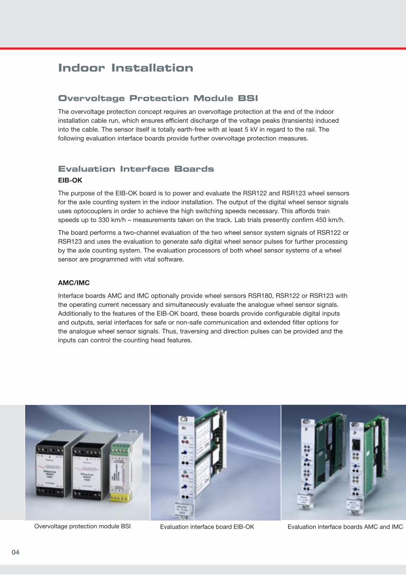
Overvoltage Protection Module BSI The overvoltage protection concept requires an overvoltage protection at the end of the indoor installation cable run, which ensures efficient discharge of the voltage peaks (transients) induced into the cable. The sensor itself is totally earth-free with at least 5 kV in regard to the rail. The following evaluation interface boards provide further overvoltage protection measures.
Evaluation Interface BoardsEIB-OK
The purpose of the EIB-OK board is to power and evaluate the RSR122 and RSR123 wheel sensors for the axle counting system in the indoor installation. The output of the digital wheel sensor signals uses optocouplers in order to achieve the high switching speeds necessary. This affords train speeds up to 330 km/h – measurements taken on the track. Lab trials presently confirm 450 km/h.
The board performs a two-channel evaluation of the two wheel sensor system signals of RSR122 or RSR123 and uses the evaluation to generate safe digital wheel sensor pulses for further processing by the axle counting system. The evaluation processors of both wheel sensor systems of a wheel sensor are programmed with vital software.
AMC/IMC
Interface boards AMC and IMC optionally provide wheel sensors RSR180, RSR122 or RSR123 with the operating current necessary and simultaneously evaluate the analogue wheel sensor signals. Additionally to the features of the EIB-OK board, these boards provide configurable digital inputs and outputs, serial interfaces for safe or non-safe communication and extended filter options for the analogue wheel sensor signals. Thus, traversing and direction pulses can be provided and the inputs can control the counting head features.
Indoor Installation
Overvoltage protection module BSI Evaluation interface board EIB-OK Evaluation interface boards AMC and IMC

0�
Fuse Boards The SIB fuse board comprises a polarity reversal protection, excess-current releases and voltage stabilising capacitors for transient stabilisation of the power supply.
The SIC fuse board additionally comprises supply voltage monitoring so that in case of voltage rise above the threshold value, the axle counting system will change automatically into a safe status. Thus, no other measures are necessary to monitor the input voltage of the ACS2000 provided by the power supply or by other signalling devices.
Processor BoardsACB Axle Counting Board
The axle counting board ACB detects the wheel pulses of the connected counting heads of a track section and generates a safe track clear indication. One ACB allows simultaneous processing of 6 wheel sensor signals. For system reset, there is a two-channel input. Conditions for reset and reset procedure can be configured according to the railway operator needs.
For applications where the safe track clear indication of a track section is to be made available for two operating units, two ACB axle counting boards can communicate using a serial connection (RS232 modem). The distance between the two operating units is only limited by the efficiency of the transmission system.
A second serial interface on the front face of the board allows connection of a standard laptop for read out and evaluation of diagnostics data.
DIOB Digital Input/Output Board
For applications where the track clear indication of a track section is to be made available for two operating posts, the DIOB board allows input of another 16 one-channel data (optocoupler) and direct relay output at the opposite side. Transmission is bi-directional and offers signalling safety (EN 50159-1). For the purpose of further safe processing in the signalling system, the data is transmitted using multiple equivalent channels.
Fuse boards SIB and SIC Axle counting board ACB Digital input/output board DIOB

0�
Mounting and Cabling In compliance with the project, evaluation, fuse and processor boards are inserted into 19“ board racks. The boards of a counting section are electrically connected at the axle counting backplane ABP. As a rule, one rack with 84 pitch units can monitor 4 track sections. Internal ACS2000 connections between the ABP backplanes are now implemented using standar-dized patch cables with RJ45 connectors. The cabling is thus extremely easy to change.
Board rack BGTBackplane ABP

0�www.frauscher.com
Diagnostics Communication Interface Boards and PC-Tool
Diagnostics uses a Windows-based application that can be used on any standard PC. The diagnostics functions are detailed down to the counting head level. Special communication interface boards allow the diagnostics to acquire data of up to 128 counting sections and forward them over a serial interface to a maintenance center for further evaluation

0�
Due to open and universal interfaces, it is easy to adapt the ACS2000 Axle Counting System to a large number of different signalling systems.The advantages of this easy and straightforward structure become clear as early as the project stage. After definition of the track insulation plan, the axle counting system can be projected within a short period of time. The project-specific board racks are delivered for the signalling system and connected via cable to the counting heads.Counting heads are delivered pre-mounted on the rail claw and for the respective rail profile, thus only mounting at the foot of rail and connection to the earthing cable are necessary.Adjustments on site comprise the electrical adjustment of the wheel sensors at the rail (RSR122 and RSR123) as well as testing and, if necessary, correction of counting direction per counting head using the adjustment switches in the indoor installation. Commissioning follows a test procedure that re-checks all adjustments made.
www.frauscher.com
Adaptation, Planning and Project Planning

0�
Station
ACB – Axle counting board, ABP – Axle counting backplane, BGT – Board rack, BSI – Overvoltage protection board, EB – Evaluation interface board, FMA – Track section, GAK – Track connection box, RSR – Wheel sensor, ZP – Counting head
Station A Block section Station B
Application example isolated operation
Application example transmission mode
ZP 2 ZP 4
ZP 5 ZP 6ZP 3ZP 1
Outdoor equipment
Indoor installation
Double usage Double usage Double usage Double usage
Track clear indication Track clear indication Track clear indication Track clear indicationTrack section Track section Track section Track section
Track clear indication Track clear indication Track clear indication Track clear indication Track clear indication Track clear indication

10
Data and Facts
> Monitoring of track sections with a maximum of � (1�) counting heads allowing
simultaneous traversing,
> Triple usage of counting heads for axle counting and switching tasks,
> Swing safe evaluation of axles,
> Traversing speeds of 0 to ��0 km/h (lab trials showed up to ��0 km/h),
> Safe control of electro-magnetic rail brake and eddy current brake,
> The wheel sensor system allows for distances of 10 km between wheel sensor and
evaluation board,
> Design and evaluation according to CENELEC standards,
> Easy project planning of axle counting system,
> Configurable reset conditions and procedures,
> Signal-safe communication and data transmission between two axle counting
boards in compliance with EN �01��-1 (CENELEC) using RS��� and a suitable
transmission system,
> Separate interface to read out diagnostics data.

11www.frauscher.com
Application Examples
The system applies not only to long-distance traffic, but also to short-distance traffic. This required the axle counting system to be able to operate safely and reliably, irrespective of special rail pro-files and location of the wheel sensors. For example, grooved rail in road traffic areas as well as special wheel profiles and bogies with underfloor components (e.g. electro-magnetic rail brake).
South Africa AustriaNetherlands
Vietnam SloveniaAustralia

Frauscher GmbH | Gewerbestraße 14774 St. Marienkirchen | AustriaPhone +43 (0) 77 11 / 29 20 - 0 Fax +43 (0) 77 11 / 29 20 - [email protected] | www.frauscher.com
High Quality Components for Railway Safety.
Exc
lud
ing
typ
os
/ p
rintin
g e
rro
rs a
nd s
ubje
ct t
o c
hang
es in
co
nstr
uctio
n.