free-flyer acquisition of spinning objects with gecko-inspired
TRANSCRIPT
Free-Flyer Acquisition of Spinning Objectswith Gecko-Inspired Adhesives
Matthew A. Estrada,* Benjamin Hockman,* Andrew Bylard,* Elliot W. Hawkes,Mark R. Cutkosky, and Marco Pavone
Abstract— We explore the use of grippers with gecko-inspiredadhesives for spacecraft docking and acquisition of tumblingobjects in microgravity. Towards the goal of autonomousobject manipulation in space, adhesive grippers mounted onplanar free-floating platforms are shown to be tolerant ofa range of incoming linear and angular velocities. Throughmodeling, simulations, and experiments, we characterize thedynamic “grasping envelope” for successful acquisition andderive insights to inform future gripper designs and graspingstrategies for motion planning.
I. INTRODUCTION
Robotic manipulators capable of reliably attaching and de-taching from target objects are critical to many ongoing andemerging space-based applications (e.g., docking maneuvers,orbital debris removal, and on-orbit servicing). Recently,there has been a particular interest in small assistive free-flyers that could grasp and manipulate payloads inside andoutside space vehicles [1]–[3]. Ideally, their grippers wouldalso enable them to dock onto the external hulls of spacecraftand debris for monitoring, repair, or object redirection.
Traditional approaches to grasping use hands or grippersthat either compress opposing faces of the target to generatefriction (as in the International Space Station's Canadarm),or grapple around features to lock the object in place (as inthe Orbital Express Capture System). An extensive literatureaddresses grasp planning with internal forces and friction [4].However, conventional grippers often require “cooperative"targets with low speeds relative to the manipulator. Evenwhen catching fast-moving objects (e.g., [5]), or when grasp-ing objects from a flying or floating platform [6]–[10], thecontext generally assumes an uncluttered workspace so thatthe hand or gripper can wrap around the object or grapplingfixture to grasp it with internal forces.
Alternatives include astrictive grippers [11] that hold anobject using suction or electrostatic attraction, etc. However,suction will clearly not work in a vacuum (e.g. outside aspace vehicle) and electrostatics may pose a concern whenhandling electronics. In addition, most astrictive grippersrequire the continual provision of power.
Instead, practical solutions can be found in “contigutive”grippers [11], which rely on contact and surface adhesion.
M.A. Estrada, E.W. Hawkes, and M.R. Cutkosky are with the MechanicalEngineering Dept., Stanford University. B. Hockman, A. Bylard, and M.Pavone are with the Aeronautics and Astronautics Dept., Stanford Univer-sity, Stanford, CA 94305.Emails: estrada1, bhockman, bylard, ewhawkes, cutkosky, pavone @stan-ford.edu*These authors contributed equally to this work.
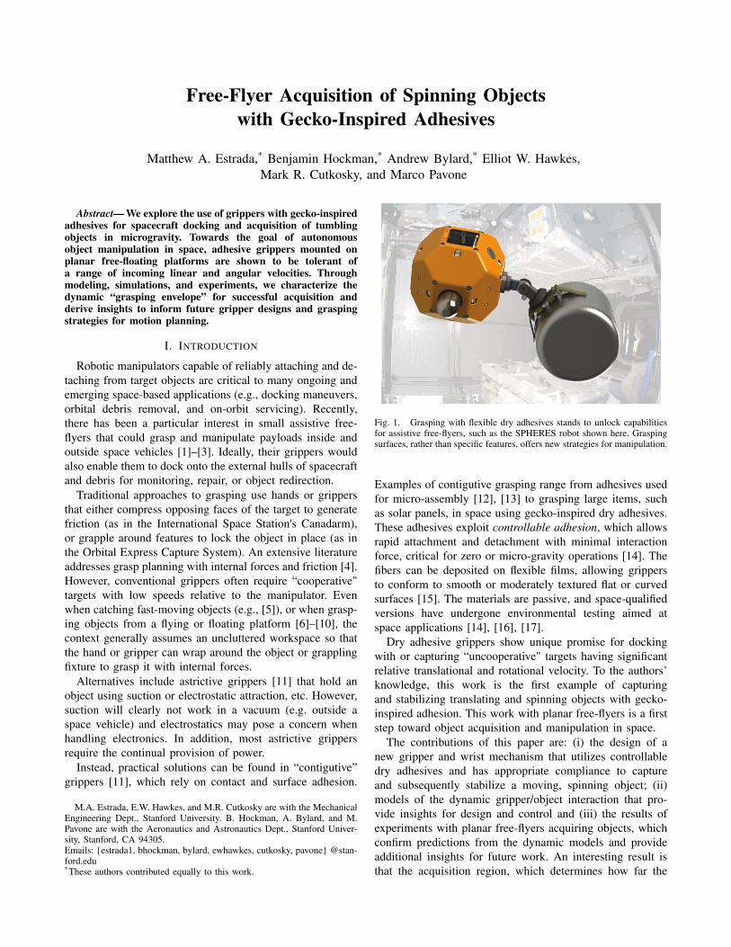
Fig. 1. Grasping with flexible dry adhesives stands to unlock capabilitiesfor assistive free-flyers, such as the SPHERES robot shown here. Graspingsurfaces, rather than specific features, offers new strategies for manipulation.
Examples of contigutive grasping range from adhesives usedfor micro-assembly [12], [13] to grasping large items, suchas solar panels, in space using gecko-inspired dry adhesives.These adhesives exploit controllable adhesion, which allowsrapid attachment and detachment with minimal interactionforce, critical for zero or micro-gravity operations [14]. Thefibers can be deposited on flexible films, allowing grippersto conform to smooth or moderately textured flat or curvedsurfaces [15]. The materials are passive, and space-qualifiedversions have undergone environmental testing aimed atspace applications [14], [16], [17].
Dry adhesive grippers show unique promise for dockingwith or capturing “uncooperative" targets having significantrelative translational and rotational velocity. To the authors’knowledge, this work is the first example of capturingand stabilizing translating and spinning objects with gecko-inspired adhesion. This work with planar free-flyers is a firststep toward object acquisition and manipulation in space.
The contributions of this paper are: (i) the design of anew gripper and wrist mechanism that utilizes controllabledry adhesives and has appropriate compliance to captureand subsequently stabilize a moving, spinning object; (ii)models of the dynamic gripper/object interaction that pro-vide insights for design and control and (iii) the results ofexperiments with planar free-flyers acquiring objects, whichconfirm predictions from the dynamic models and provideadditional insights for future work. An interesting result isthat the acquisition region, which determines how far the

Fig. 2. Adhesive gripper and compliant wrist for acquiring and stabilizingmoving, spinning objects.
gripper can be offset from the line of approach of the object,depends strongly on the relative angular velocity. Taking thisinto consideration allows for solutions in which the grippergently touches a spinning object and effectively rolls orwraps into a stable grasp.
II. GRIPPER DESIGN
A. Curved Surface Gripping
The presented gripper makes use of recent developmentsin the grasping of convex surfaces using gecko-inspiredadhesives deposited on a thin film. When the adhesivecontacts a surface and shear stress is applied in the film’spreferred direction, the fibers lay against the surface andadhere to it [15].
The gripper presented here is composed of two opposingflexible adhesive films, each held taut by a hinged, bistablearm mechanism mounted on a frame, as depicted in Fig. 3A.When a surface pushes against the triggers, the arms collapse,engaging the adhesive films (Fig. 3B). The films conform toconvex surfaces and adhere, after which significant normaland shear forces and moments can be applied (Fig. 3C). Thespan of the gripper is 26 cm, with each arm holding a 3×9cm adhesive film for a total adhesive area of 54 cm2.
B. Compliant Gripper Wrist
Linear and rotational compliance in the wrist mechanismenables the gripper to passively align to target objects anddissipate kinetic energy.
For ease of adjustment, the wrist mechanism is split intothree separable compliance elements. The gripper is mountedon a hinge providing rotational compliance. The hinge isattached to a flexure which adds transverse compliance,followed by a linear mechanism that provides compliancein the normal direction (Fig. 3D).
Since this work focuses on initial capture and absorptionof kinetic energy to maintain grip, only springs were consid-ered in the design. In future work, additional damping willsuppress oscillations after object acquisition.
Flexure Hinge
Flexible Adhesive
Frame Body
Triggers
Arm
Touch to Surface
A.
B.
C.
Linear Mechanism
Apply Forces and Moments
Shearforcefromadhesive
Normalforcefromframe
D.
Spring-loaded
Adhesives grip surface
Fig. 3. (A) Diagram of the flexible adhesive gripper. (B) When touchedgently to a surface, the triggers collapse the bistable arms, wrapping theadhesive around the object. (C) Once the film is engaged with the surface,forces and moments can be applied. (D) Wrist mechanism with decoupledcompliance in normal, transverse, and rotational directions.
III. DYNAMIC MODELING
This section proposes two dynamic models that providecomplimentary insights into the process of gripper/objectinteractions, and how to characterize and leverage the robustproperties of curved surface grippers.
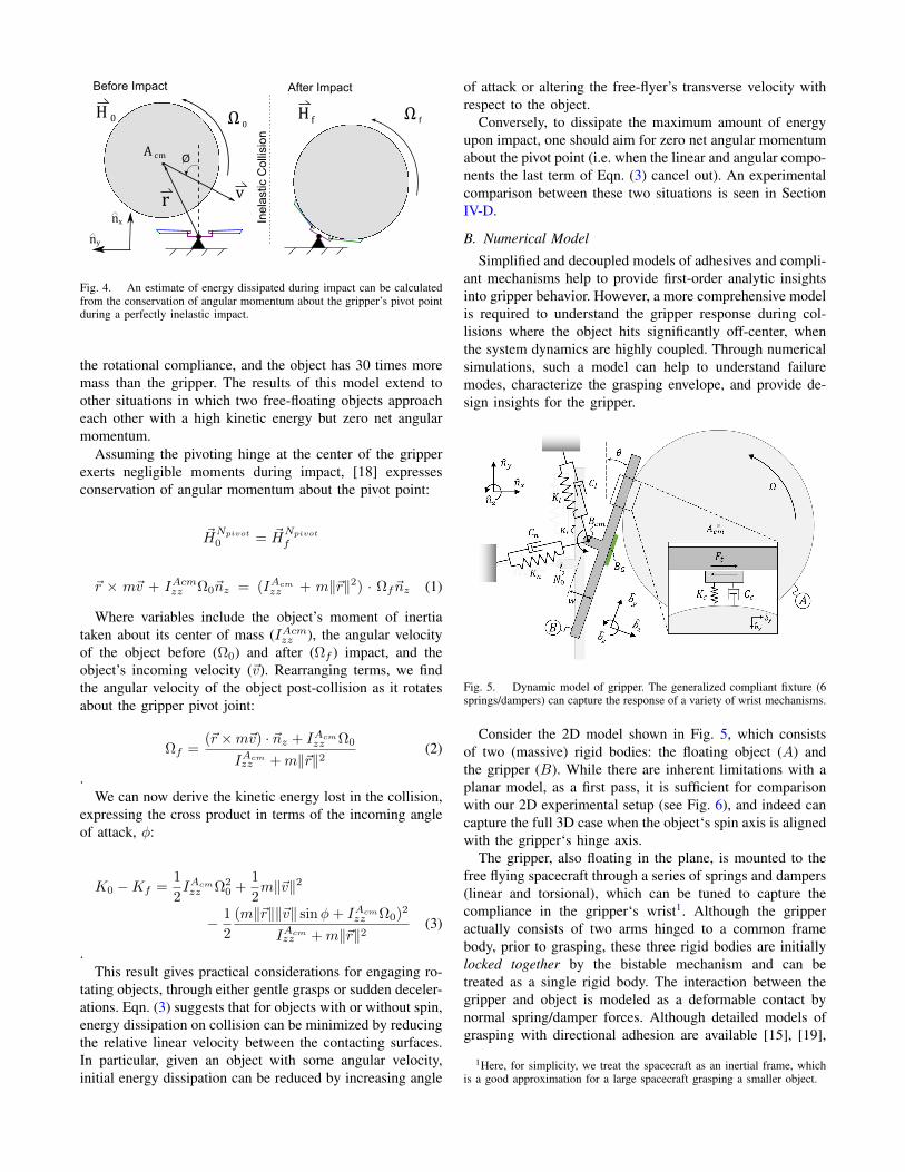
A. Impact as a Perfectly Inelastic Collision
As a starting point, a very simple planar inelastic collisionmodel provides some useful first-order insights into howenergy is dissipated upon gripper engagement. For scenarioswhere an object impacts at the center of the gripper, thegripper arms immediately collapse and engage the object.Such engagements can be modeled to a good approximationas purely inelastic collision at the center-point of the gripper.That is, once the gripper and object collide, they both rotateabout the pivot point as a single rigid body (see Fig. 4).
This inelastic assumption enables a closed-form solutionand provides an intuitive sense for how much energy willbe dissipated during initial impact. For simplicity, we ignorenon-rotational compliance in the gripper and assume its massis negligible compared to the target object’s mass. Indeed, thetranslational compliance in our gripper is much stiffer than
v
Ω 0Ω f
A cm
r
H 0 H f
Before Impact After Impact
Inel
astic
Col
lisio
n
ny
nx
Ø
Fig. 4. An estimate of energy dissipated during impact can be calculatedfrom the conservation of angular momentum about the gripper’s pivot pointduring a perfectly inelastic impact.
the rotational compliance, and the object has 30 times moremass than the gripper. The results of this model extend toother situations in which two free-floating objects approacheach other with a high kinetic energy but zero net angularmomentum.
Assuming the pivoting hinge at the center of the gripperexerts negligible moments during impact, [18] expressesconservation of angular momentum about the pivot point:
~HNpivot
0 = ~HNpivot
f
~r × m~v + IAcmzz Ω0~nz = (IAcmzz + m‖~r‖2) · Ωf~nz (1)
Where variables include the object’s moment of inertiataken about its center of mass (IAcmzz ), the angular velocityof the object before (Ω0) and after (Ωf ) impact, and theobject’s incoming velocity (~v). Rearranging terms, we findthe angular velocity of the object post-collision as it rotatesabout the gripper pivot joint:
Ωf =(~r ×m~v) · ~nz + IAcm
zz Ω0
IAcmzz +m‖~r‖2
(2)
.We can now derive the kinetic energy lost in the collision,
expressing the cross product in terms of the incoming angleof attack, φ:
K0 −Kf =1
2IAcmzz Ω2
0 +1
2m‖~v‖2
− 1
2
(m‖~r‖‖~v‖ sinφ+ IAcmzz Ω0)2
IAcmzz +m‖~r‖2
(3)
.This result gives practical considerations for engaging ro-
tating objects, through either gentle grasps or sudden deceler-ations. Eqn. (3) suggests that for objects with or without spin,energy dissipation on collision can be minimized by reducingthe relative linear velocity between the contacting surfaces.In particular, given an object with some angular velocity,initial energy dissipation can be reduced by increasing angle
of attack or altering the free-flyer’s transverse velocity withrespect to the object.
Conversely, to dissipate the maximum amount of energyupon impact, one should aim for zero net angular momentumabout the pivot point (i.e. when the linear and angular compo-nents the last term of Eqn. (3) cancel out). An experimentalcomparison between these two situations is seen in SectionIV-D.
B. Numerical Model
Simplified and decoupled models of adhesives and compli-ant mechanisms help to provide first-order analytic insightsinto gripper behavior. However, a more comprehensive modelis required to understand the gripper response during col-lisions where the object hits significantly off-center, whenthe system dynamics are highly coupled. Through numericalsimulations, such a model can help to understand failuremodes, characterize the grasping envelope, and provide de-sign insights for the gripper.
Fig. 5. Dynamic model of gripper. The generalized compliant fixture (6springs/dampers) can capture the response of a variety of wrist mechanisms.
Consider the 2D model shown in Fig. 5, which consistsof two (massive) rigid bodies: the floating object (A) andthe gripper (B). While there are inherent limitations with aplanar model, as a first pass, it is sufficient for comparisonwith our 2D experimental setup (see Fig. 6), and indeed cancapture the full 3D case when the object‘s spin axis is alignedwith the gripper‘s hinge axis.
The gripper, also floating in the plane, is mounted to thefree flying spacecraft through a series of springs and dampers(linear and torsional), which can be tuned to capture thecompliance in the gripper‘s wrist1. Although the gripperactually consists of two arms hinged to a common framebody, prior to grasping, these three rigid bodies are initiallylocked together by the bistable mechanism and can betreated as a single rigid body. The interaction between thegripper and object is modeled as a deformable contact bynormal spring/damper forces. Although detailed models ofgrasping with directional adhesion are available [15], [19],
1Here, for simplicity, we treat the spacecraft as an inertial frame, whichis a good approximation for a large spacecraft grasping a smaller object.
the gripper/object contact in the current application producesa positive normal pressure immediately on contact, so thatone can approximate the adhesive limit with anisotropicfriction:
|Ft| ≤
Ft,min + αFn, in adhesive directionµFn, against adhesive direction
(4)
.This model is shown to be in agreement with experimental
data in Section IV.With the forces from the elastic fixture and contact model,
the equations of motion for each body simply follow fromNewton’s second law, yielding a 12 state system (3 positionand 3 velocity for each body).
Because this formulation treats the gripper as a single rigidbody and cannot “lock on” to the object, a “graspable state”must be defined in order to compare simulations with thebinary success/failure results from experiments. The graspingcriteria are defined as:
1) Object contacts gripper within δx offset from BG,AND
2) |Ω| < Ωmax
The first criterion is illustrated by the green shaded region inFig. 5. The second criterion captures the gripper’s inabilityto grasp (even well positioned) fast spinning objects. Asdiscussed in Section IV, these criteria match experimentalobservations.
IV. FREE-FLYER EXPERIMENTS
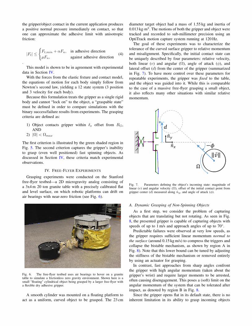
Grasping experiments were conducted on the Stanfordfree-flyer testbed—a 2D microgravity analog consisting ofa 3x4 m 20 ton granite table with a precisely calibrated flatand level surface, on which robotic platforms can drift onair bearings with near-zero friction (see Fig. 6).
Fig. 6. The free-flyer testbed uses air bearings to hover on a granitetable to simulate a frictionless zero gravity environment. Shown here is asmall "floating" cylindrical object being grasped by a larger free-flyer witha flexible dry adhesive gripper.
A smooth cylinder was mounted on a floating platform toact as a uniform, curved object to be grasped. The 23 cm
diameter target object had a mass of 1.55 kg and inertia of0.013 kg·m2. The motions of both the gripper and object weretracked and recorded to sub-millimeter precision using anOptiTrack motion capture system running at 120 Hz.
The goal of these experiments was to characterize thetolerance of the curved surface gripper to relative momentumand misalignment. Specifically, the initial contact state canbe uniquely described by four parameters: relative velocity,both linear (v) and angular (Ω), angle of attack (φ), andlateral offset (d) from the center of the gripper (summarizedin Fig. 7). To have more control over these parameters forrepeatable experiments, the gripper was fixed to the table,and the object was guided into it. While this is comparableto the case of a massive free-flyer grasping a small object,it also reflects many other situations with similar relativemomentum.
𝑛𝑥
𝑛𝑦
Ω
−𝜙
𝑣
𝑑
Fig. 7. Parameters defining the object’s incoming state: magnitude oflinear (v) and angular velocity (Ω), offset of the initial contact point fromgripper center (d) measured along ny , and angle of attack (φ).
A. Dynamic Grasping of Non-Spinning Objects
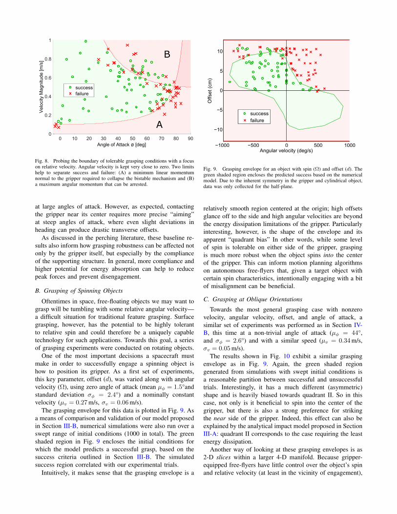
As a first step, we consider the problem of capturingobjects that are translating but not rotating. As seen in Fig.8, the presented gripper is capable of capturing objects withspeeds of up to 1 m/s and approach angles of up to 70°.
Predictable failures were observed at very low speeds, asthe gripper requires sufficient linear momentum normal tothe surface (around 0.15 kg m/s) to compress the triggers andcollapse the bistable mechanism, as shown by region A inFig. 8). Note that this lower bound can be tuned by adjustingthe stiffness of the bistable mechanism or removed entirelyby using an actuator for grasping.
In contrast, fast approaches from sharp angles confrontthe gripper with high angular momentum (taken about thegripper’s wrist) and require larger moments to be arrested,often causing disengagement. This poses a (soft) limit on theangular momentum of the system that can be tolerated afterimpact, as denoted by region B in Fig. 8.
Since the gripper opens flat in its default state, there is noinherent limitation in its ability to grasp incoming objects
Angle of Attack ø [deg]0 10 20 30 40 50 60 70 80 90
Vel
ocity
Mag
nitu
de [m
/s]
0
0.2
0.4
0.6
0.8
1
successfailure
A
B
Fig. 8. Probing the boundary of tolerable grasping conditions with a focuson relative velocity. Angular velocity is kept very close to zero. Two limitshelp to separate success and failure: (A) a minimum linear momentumnormal to the gripper required to collapse the bistable mechanism and (B)a maximum angular momentum that can be arrested.
at large angles of attack. However, as expected, contactingthe gripper near its center requires more precise “aiming”at steep angles of attack, where even slight deviations inheading can produce drastic transverse offsets.
As discussed in the perching literature, these baseline re-sults also inform how grasping robustness can be affected notonly by the gripper itself, but especially by the complianceof the supporting structure. In general, more compliance andhigher potential for energy absorption can help to reducepeak forces and prevent disengagement.
B. Grasping of Spinning Objects
Oftentimes in space, free-floating objects we may want tograsp will be tumbling with some relative angular velocity—a difficult situation for traditional feature grasping. Surfacegrasping, however, has the potential to be highly tolerantto relative spin and could therefore be a uniquely capabletechnology for such applications. Towards this goal, a seriesof grasping experiments were conducted on rotating objects.
One of the most important decisions a spacecraft mustmake in order to successfully engage a spinning object ishow to position its gripper. As a first set of experiments,this key parameter, offset (d), was varied along with angularvelocity (Ω), using zero angle of attack (mean µφ = 1.5°andstandard deviation σφ = 2.4°) and a nominally constantvelocity (µv = 0.27 m/s, σv = 0.06 m/s).
The grasping envelope for this data is plotted in Fig. 9. Asa means of comparison and validation of our model proposedin Section III-B, numerical simulations were also run over aswept range of initial conditions (1000 in total). The greenshaded region in Fig. 9 encloses the initial conditions forwhich the model predicts a successful grasp, based on thesuccess criteria outlined in Section III-B. The simulatedsuccess region correlated with our experimental trials.
Intuitively, it makes sense that the grasping envelope is a
−1000 −500 0 500 1000
−10
−5
0
5
10
Angular velocity (deg/s)
Offs
et (
cm)
successfailure
Fig. 9. Grasping envelope for an object with spin (Ω) and offset (d). Thegreen shaded region encloses the predicted success based on the numericalmodel. Due to the inherent symmetry in the gripper and cylindrical object,data was only collected for the half-plane.
relatively smooth region centered at the origin; high offsetsglance off to the side and high angular velocities are beyondthe energy dissipation limitations of the gripper. Particularlyinteresting, however, is the shape of the envelope and itsapparent “quadrant bias” In other words, while some levelof spin is tolerable on either side of the gripper, graspingis much more robust when the object spins into the centerof the gripper. This can inform motion planning algorithmson autonomous free-flyers that, given a target object withcertain spin characteristics, intentionally engaging with a bitof misalignment can be beneficial.
C. Grasping at Oblique Orientations
Towards the most general grasping case with nonzerovelocity, angular velocity, offset, and angle of attack, asimilar set of experiments was performed as in Section IV-B, this time at a non-trivial angle of attack (µφ = 44°,and σφ = 2.6°) and with a similar speed (µv = 0.34 m/s,σv = 0.05 m/s).
The results shown in Fig. 10 exhibit a similar graspingenvelope as in Fig. 9. Again, the green shaded regiongenerated from simulations with swept initial conditions isa reasonable partition between successful and unsuccessfultrials. Interestingly, it has a much different (asymmetric)shape and is heavily biased towards quadrant II. So in thiscase, not only is it beneficial to spin into the center of thegripper, but there is also a strong preference for strikingthe near side of the gripper. Indeed, this effect can also beexplained by the analytical impact model proposed in SectionIII-A: quadrant II corresponds to the case requiring the leastenergy dissipation.
Another way of looking at these grasping envelopes is as2-D slices within a larger 4-D manifold. Because gripper-equipped free-flyers have little control over the object’s spinand relative velocity (at least in the vicinity of engagement),

−1000 −500 0 500 1000
−10
−5
0
5
10
Angular velocity (deg/s)
Offs
et (
cm)
successfailure
Fig. 10. Grasping envelope for spinning objects at a 45° angle of attack. Thegreen shaded region encloses the predicted success based on the numericalmodel.
these 2-D slices can help them decide how to control theirrelative alignment (d) and orientation (φ) to increase theirchances of a successful grasp. For example, a non-spinningobject has the greatest offset tolerance with a head-onengagement (i.e. φ = 0 in Fig. 9), whereas a slowly spinningobject may be more robustly captured at an oblique angle ofattack (i.e. φ < 0 in Fig. 10).
D. Angular Momentum and Energy Dissipation
Net angular momentum was observed to have a large effecton the gripper dynamics after engagement. Consider twosimilar cases depicted in Fig. 11. In each case, the objects ap-proach at a 45°angle of attack, have similar linear velocities,and have the same offset and angular velocity magnitude.However, the direction of the spin is reversed, resulting in alarge disparity in the incoming angular momentum of eachobject, calculated about the gripper’s hinge joint.
Notice the very different behaviors in Fig. 11 with the“despin” maneuver dissipating much more energy than the“rolling” engagement. Making the gross assumption thatangular momentum is held constant during an inelasticimpact, as detailed in Section III-A, the calculated kineticenergy before and after impact is superimposed on the plot.
With appreciable compliance in the gripper’s wrist, theassumption of a rigid impact deviates from reality. The “de-spin” maneuver recovers a portion of the model’s dissipatedenergy from the energy stored in the flexure mounted behindthe pivoting joint. The rolling case likely experiences extraenergy dissipation through slippage at the adhesive’s surfacebefore engaging and pivoting. Even with these second-ordereffects considered, a perfectly inelastic collision providesintuitive insight for attachment maneuvers.
V. CONCLUSIONS AND FUTURE WORK
Our curved surface gripper has been shown to successfullygrasp a rotating object with a wide range of linear androtational velocities. Models show that energy dissipation in
vΩ0H0 Hf
v
H0
Rolling Despin
HfΩ0
time [s]-0.2 -0.1 0 0.1 0.2 0.3 0.4 0.5K
inet
ic E
nerg
y [J
], A
ngul
ar V
eloc
ity [r
ad/s
ec *
10-2
]
-0.1
-0.05
0
0.05
0.1
0.15
0.2
0.25
0.3
0.35
0.4
Roll Angular VelocityRoll Kinetic EnergyRoll Predicted EnergyDespin Angular VelocityDespin Kinetic EnergyDespin Predicted Energy
Fig. 11. Demonstration of maximum energy dissipation on collision in“despin” scenarios, characterized by net zero angular momentum, vs. thecase where spin is in the opposite direction, where a “rolling” effect occurs.
the first moments of impact is highly dependent upon the netangular velocity of the system. Calculating energy dissipatedduring collision sheds light on whether the gripper canremain attached as an object comes to rest within its grasp.Additionally, an object’s interaction with the adhesive beforeattachment can either push it into a successful engagementor vice versa.
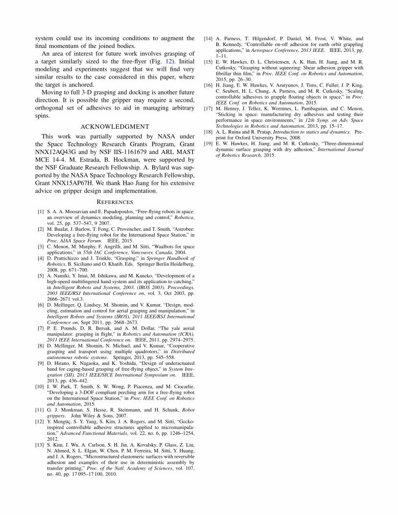
Fig. 12. Gripper mounted on a lightweight floating platform for small-target grasping experiments.
A gripper capable of attaching under a variety of incomingconditions opens the possibility of manipulation utilizinga free-flyer’s momentum. Tolerance to parameters such asoffset in the gripper’s attachment point, an oblique angle ofattack, and relative angular velocity all provide degrees offreedom to shape the angular momentum of an incomingplatform. Considering the net momentum of the free-flyerand grasped object will be a sum of the parts, a robotic
system could use its incoming conditions to augment thefinal momentum of the joined bodies.
An area of interest for future work involves grasping ofa target similarly sized to the free-flyer (Fig. 12). Initialmodeling and experiments suggest that we will find verysimilar results to the case considered in this paper, wherethe target is anchored.
Moving to full 3-D grasping and docking is another futuredirection. It is possible the gripper may require a second,orthogonal set of adhesives to aid in managing arbitraryspins.
ACKNOWLEDGMENTThis work was partially supported by NASA under
the Space Technology Research Grants Program, GrantNNX12AQ43G and by NSF IIS-1161679 and ARL MASTMCE 14-4. M. Estrada, B. Hockman, were supported bythe NSF Graduate Research Fellowship. A. Bylard was sup-ported by the NASA Space Technology Research Fellowship,Grant NNX15AP67H. We thank Hao Jiang for his extensiveadvice on gripper design and implementation.
REFERENCES
[1] S. A. A. Moosavian and E. Papadopoulos, “Free-flying robots in space:an overview of dynamics modeling, planning and control,” Robotica,vol. 25, pp. 537–547, 9 2007.
[2] M. Bualat, J. Barlow, T. Fong, C. Provencher, and T. Smith, “Astrobee:Developing a free-flying robot for the International Space Station,” inProc. AIAA Space Forum. IEEE, 2015.
[3] C. Menon, M. Murphy, F. Angrilli, and M. Sitti, “Waalbots for spaceapplications,” in 55th IAC Conference, Vancouver, Canada, 2004.
[4] D. Prattichizzo and J. Trinkle, “Grasping,” in Springer Handbook ofRobotics, B. Siciliano and O. Khatib, Eds. Springer Berlin Heidelberg,2008, pp. 671–700.
[5] A. Namiki, Y. Imai, M. Ishikawa, and M. Kaneko, “Development of ahigh-speed multifingered hand system and its application to catching,”in Intelligent Robots and Systems, 2003. (IROS 2003). Proceedings.2003 IEEE/RSJ International Conference on, vol. 3, Oct 2003, pp.2666–2671 vol.3.
[6] D. Mellinger, Q. Lindsey, M. Shomin, and V. Kumar, “Design, mod-eling, estimation and control for aerial grasping and manipulation,” inIntelligent Robots and Systems (IROS), 2011 IEEE/RSJ InternationalConference on, Sept 2011, pp. 2668–2673.
[7] P. E. Pounds, D. R. Bersak, and A. M. Dollar, “The yale aerialmanipulator: grasping in flight,” in Robotics and Automation (ICRA),2011 IEEE International Conference on. IEEE, 2011, pp. 2974–2975.
[8] D. Mellinger, M. Shomin, N. Michael, and V. Kumar, “Cooperativegrasping and transport using multiple quadrotors,” in Distributedautonomous robotic systems. Springer, 2013, pp. 545–558.
[9] D. Hirano, K. Nagaoka, and K. Yoshida, “Design of underactuatedhand for caging-based grasping of free-flying object,” in System Inte-gration (SII), 2013 IEEE/SICE International Symposium on. IEEE,2013, pp. 436–442.
[10] I. W. Park, T. Smith, S. W. Wong, P. Piacenza, and M. Ciocarlie,“Developing a 3-DOF compliant perching arm for a free-flying roboton the International Space Station,” in Proc. IEEE Conf. on Roboticsand Automation, 2015.
[11] G. J. Monkman, S. Hesse, R. Steinmann, and H. Schunk, Robotgrippers. John Wiley & Sons, 2007.
[12] Y. Mengüç, S. Y. Yang, S. Kim, J. A. Rogers, and M. Sitti, “Gecko-inspired controllable adhesive structures applied to micromanipula-tion,” Advanced Functional Materials, vol. 22, no. 6, pp. 1246–1254,2012.
[13] S. Kim, J. Wu, A. Carlson, S. H. Jin, A. Kovalsky, P. Glass, Z. Liu,N. Ahmed, S. L. Elgan, W. Chen, P. M. Ferreira, M. Sitti, Y. Huang,and J. A. Rogers, “Microstructured elastomeric surfaces with reversibleadhesion and examples of their use in deterministic assembly bytransfer printing,” Proc. of the Natl. Academy of Sciences, vol. 107,no. 40, pp. 17 095–17 100, 2010.
[14] A. Parness, T. Hilgendorf, P. Daniel, M. Frost, V. White, andB. Kennedy, “Controllable on-off adhesion for earth orbit grapplingapplications,” in Aerospace Conference, 2013 IEEE. IEEE, 2013, pp.1–11.
[15] E. W. Hawkes, D. L. Christensen, A. K. Han, H. Jiang, and M. R.Cutkosky, “Grasping without squeezing: Shear adhesion gripper withfibrillar thin film,” in Proc. IEEE Conf. on Robotics and Automation,2015, pp. 26–30.
[16] H. Jiang, E. W. Hawkes, V. Arutyunov, J. Tims, C. Fuller, J. P. King,C. Seubert, H. L. Chang, A. Parness, and M. R. Cutkosky, “Scalingcontrollable adhesives to grapple floating objects in space,” in Proc.IEEE Conf. on Robotics and Automation, 2015.
[17] M. Henrey, J. Tellez, K. Wormnes, L. Pambaguian, and C. Menon,“Sticking in space: manufacturing dry adhesives and testing theirperformance in space environments,” in 12th Symp. on Adv. SpaceTechnologies in Robotics and Automation, 2013, pp. 15–17.
[18] A. L. Ruina and R. Pratap, Introduction to statics and dynamics. Pre-print for Oxford University Press, 2008.
[19] E. W. Hawkes, H. Jiang, and M. R. Cutkosky, “Three-dimensionaldynamic surface grasping with dry adhesion,” International Journalof Robotics Research, 2015.