free standing pergola assembly instructions
TRANSCRIPT
Free Standing PergolaASSEMBLY INSTRUCTIONS
Quality Control Number: Numéro de controle de qualitié:Número de control de calidad:
© 2011 Suncast Corporation, Batavia, IL 0660110
Includes instructions for 8' x 8', 8' x 12', 10' x 14', 10' x 16', 12' x 16', 14' x 14', or 14' x 20' pergola

2
CAUTION •Pergolanotintendedforuseinextremeweatherconditions.
•Do notstand,sit,orstoreitemsontopofpergola.
•Handlecarefullyinextremetemperatures.
•Repairorreplacebrokenpartsimmediately.Call1-800-444-3310forreplacementparts.
•Suncastisnotresponsiblefordamagecausedbyweatherormisuse.
•Atregularintervalsinspectyourpergolatomakesurethatassemblyintegrityhasbeenmaintained.
•Periodicallycheckthatthelocationyouhavechosentosetyourpergolaisstilllevel.
•Avoidexcessheatfromanyauxiliarysource.
•Anyadditionalholesdrilledintopartscouldcauseunsafeconditions.
•Followmanufacturersafetyinstructionswhenusingladder.
•Do notanchortopaverbricks.Foundationmustbeasolidsurface.
•Exercisecautionusingalawnmower,edgetrimmerorotheryardequipmentnearpergola.
Before You Begin...
• Consult your local authorities for any permits required to construct pergola. Priortotheconstructionofyourpergola,checkwiththelocalbuildingcodeofficialtoreviewany
requiredpermitsorbuildinglimitations.
• COMPLETE SITE PREPARATION AND FOUNDATION CONSTRUCTION BEFORE UNPACKING ALL PARTS.
Alevelandsturdyfoundationisrequiredbeforepergolaconstructioncanbegin.
• Read instructions thoroughly prior to assembly. Thiskitcontainspartsthatcanbedamagedifassembledincorrectlyorinthewrongsequence.
• Please follow instructions. IfyouhavequestionsorconcernswiththisproductDO NOTreturntostore.
Assemblyquestions?Missingparts?Call1-800-444-3310.
• Assistance is required. Duetothesizeoftheparts,atleasttwopeoplearerequiredtohandle,fitandsecurepergolacomponents.
• These instructions cover a 14' x 14' size pergola. Theassemblyprocessisthesameforeachpergolasize,butsomestepswilldifferslightly,dependingon
thesizeyouhavepurchased.
• Foundation mounting hardware varies with each application. Readmanualfirstandcontactyourlocalbuildingsupplyretailerforrecommendationsforyourapplication.
• If you live in a high-wind area, you may want to purchase the high-wind brackets (C), sold separately.

3
8'8'
Tools Needed for Installation
Pergola Safety and Care
•Washpergolawithgardenhoseormilddetergentsolutionandsoftcloth.Do notuseastiffbrushorabrasivecleanerasthatcoulddamagepergola.
•Hotitems,suchasrecentlyusedgrills,blowtorches,etc.,mustnotbeusedinornearthepergola.
Assembly Day Tips
• Complete site preparation and foundation construction before unpacking parts and beginning assembly.
• Take care when removing vinyl parts. Other parts are packed inside them.
• DO NOT attempt to assemble on a day with strong winds.
• DO NOT attempt to assemble on days when temperature is below 32 degrees.
• Set aside appropriate amount of time to completely assemble pergola. See the chart below for approximate assembly times.
8x8 8x12 10x14 10x16 12x16 14x14 14x20
5 hours 6 hours 6 hours 7 hours 8 hours 8 hours 9 hours
• Make sure you have assistance nearby to lift and secure parts in place.
• Wear light duty work gloves while assembling pergola.
• If you have questions on assembly, please call 1-800-444-3310.
Note: This product contains parts that are used in different orientations to construct the pergola. Please take note of the orientation of the parts shown throughout this instruction manual. Failure to follow instructions could result in damage to parts. Suncast is not responsible for replacing parts lost or damaged due to incorrect assembly.
4
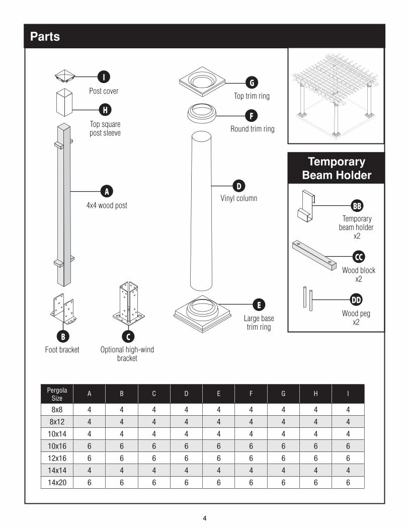
TemporaryBeam Holder
Temporarybeam holder
x2
Wood blockx2
Wood pegx2
BB
CC
DD
Optional high-windbracket
G
ELarge basetrim ring
A
H
I
CB
4x4 wood post
Top squarepost sleeve
Post cover
Foot bracket
D
Round trim ring
F
Top trim ring
Vinyl column
Parts
Pergola Size
A B C D E F G H I
8x8 4 4 4 4 4 4 4 4 4
8x12 4 4 4 4 4 4 4 4 4
10x14 4 4 4 4 4 4 4 4 4
10x16 6 6 6 6 6 6 6 6 6
12x16 6 6 6 6 6 6 6 6 6
14x14 4 4 4 4 4 4 4 4 4
14x20 6 6 6 6 6 6 6 6 6
5
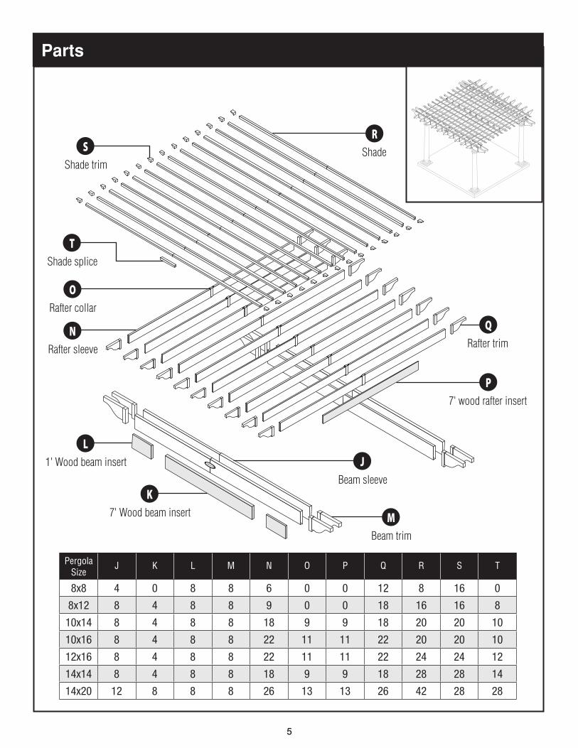
Beam sleeve
J
7' Wood beam insert
K
Beam trim
M
1' Wood beam insert
L
Rafter collar
O
Rafter sleeve
N
7' wood rafter insert
P
Rafter trim
Q
Shade trim
S
Shade splice
T
Shade
R
Parts
Pergola Size
J K L M N O P Q R S T
8x8 4 0 8 8 6 0 0 12 8 16 0
8x12 8 4 8 8 9 0 0 18 16 16 8
10x14 8 4 8 8 18 9 9 18 20 20 10
10x16 8 4 8 8 22 11 11 22 20 20 10
12x16 8 4 8 8 22 11 11 22 24 24 12
14x14 8 4 8 8 18 9 9 18 28 28 14
14x20 12 8 8 8 26 13 13 26 42 28 28
6
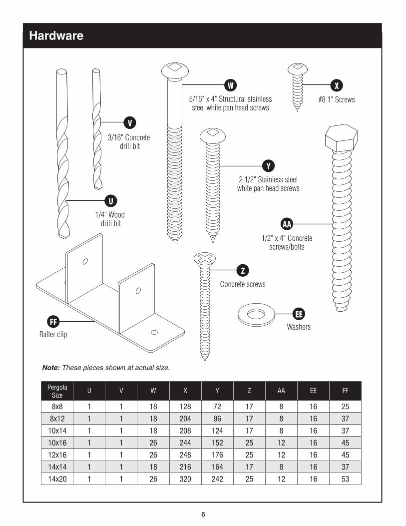
3/16" Concrete drill bit
1/4" Wood drill bit
Rafter clip
#8 1" Screws5/16" x 4" Structural stainlesssteel white pan head screws
2 1/2" Stainless steelwhite pan head screws
V
W
Y
Concrete screws
1/2" x 4" Concretescrews/bolts
Washers
Z
AA
EE
X
U
FF
Hardware
Pergola Size
U V W X Y Z AA EE FF
8x8 1 1 18 128 72 17 8 16 25
8x12 1 1 18 204 96 17 8 16 37
10x14 1 1 18 208 124 17 8 16 37
10x16 1 1 26 244 152 25 12 16 45
12x16 1 1 26 248 176 25 12 16 45
14x14 1 1 18 216 164 17 8 16 37
14x20 1 1 26 320 242 25 12 16 53
Note: These pieces shown at actual size.
7
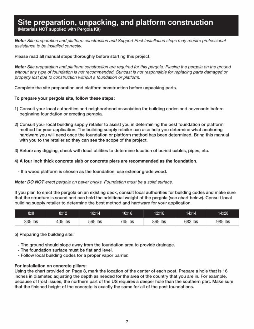
Site preparation, unpacking, and platform construction (MaterialsNOTsuppliedwithPergolaKit) Note: Site preparation and platform construction and Support Post Installation steps may require professional assistance to be installed correctly.
Pleasereadallmanualstepsthoroughlybeforestartingthisproject.
Note: Site preparation and platform construction are required for this pergola. Placing the pergola on the ground without any type of foundation is not recommended. Suncast is not responsible for replacing parts damaged or property lost due to construction without a foundation or platform.
Completethesitepreparationandplatformconstructionbeforeunpackingparts.
To prepare your pergola site, follow these steps:
1)Consultyourlocalauthoritiesandneighborhoodassociationforbuildingcodesandcovenantsbefore beginningfoundationorerectingpergola.
2)Consultyourlocalbuildingsupplyretailertoassistyouindeterminingthebestfoundationorplatform methodforyourapplication.Thebuildingsupplyretailercanalsohelpyoudeterminewhatanchoring hardwareyouwillneedoncethefoundationorplatformmethodhasbeendetermined.Bringthismanual withyoutotheretailersotheycanseethescopeoftheproject.
3)Beforeanydigging,checkwithlocalutilitiestodeterminelocationofburiedcables,pipes,etc.
4)A four inch thick concrete slab or concrete piers are recommended as the foundation.
-Ifawoodplatformischosenasthefoundation,useexteriorgradewood.
Note: Do Not erect pergola on paver bricks. Foundation must be a solid surface.
Ifyouplantoerectthepergolaonanexistingdeck,consultlocalauthoritiesforbuildingcodesandmakesurethatthestructureissoundandcanholdtheadditionalweightofthepergola(seechartbelow).Consultlocalbuildingsupplyretailertodeterminethebestmethodandhardwareforyourapplication.
5)Preparingthebuildingsite:
-Thegroundshouldslopeawayfromthefoundationareatoprovidedrainage. -Thefoundationsurfacemustbeflatandlevel. -Followlocalbuildingcodesforapropervaporbarrier.
For installation on concrete pillars:UsingthechartprovidedonPage8,markthelocationofthecenterofeachpost.Prepareaholethatis16 inchesindiameter,adjustingthedepthasneededfortheareaofthecountrythatyouarein.Forexample, becauseoffrostissues,thenorthernpartoftheUSrequiresadeeperholethanthesouthernpart.Makesurethatthefinishedheightoftheconcreteisexactlythesameforallofthepostfoundations.
8x8 8x12 10x14 10x16 12x16 14x14 14x20
335 lbs 405 lbs 565 lbs 745 lbs 865 lbs 683 lbs 985 lbs

8
Specs for post and beam layout
B (beams)
A (rafters)C
B (beams)
B (beams)
A (rafters)C
Six post layoutFour post layout
Propersitepreparationrequiresthatthelayoutissquare.Usethemeasurementsonthechartprovidedto determinethecorrectspacingoftheposts(A&B).Thediagonalmeasurement(C)willensurethatthepergolaissquare.
Note: The measurements on the chart are from center to center of the posts.
4x4 Post wrappedw/ vinyl column
Shades @ +or- 12" apart
2x6 Rafters @ +or- 16" apart
Post D
Post C
Post A
Elevation A
Elevation B
Post A & Corientation
Post B & Dorientation
Post B
2x8 Beams
Top size in feet
Rafter length including ends
in inches
Beam length including ends
in inches
# of posts # of double beams
Depth (A)in inches
Width (B)in inches
Diagonal (C)in inches
8x8 106 114 4 2 74 74 104.65
8x12 106 158 4 2 74 118 139.28
10x14 130 182 4 2 96 142 171.41
10x16 130 204 6 2 96 82 190.03
12x16 154 204 6 2 120 82 203.21
14x14 178 182 4 2 144 142 202.24
14x20 178 261 6 2 144 110.50 263.77
Specs and Dimensions
9
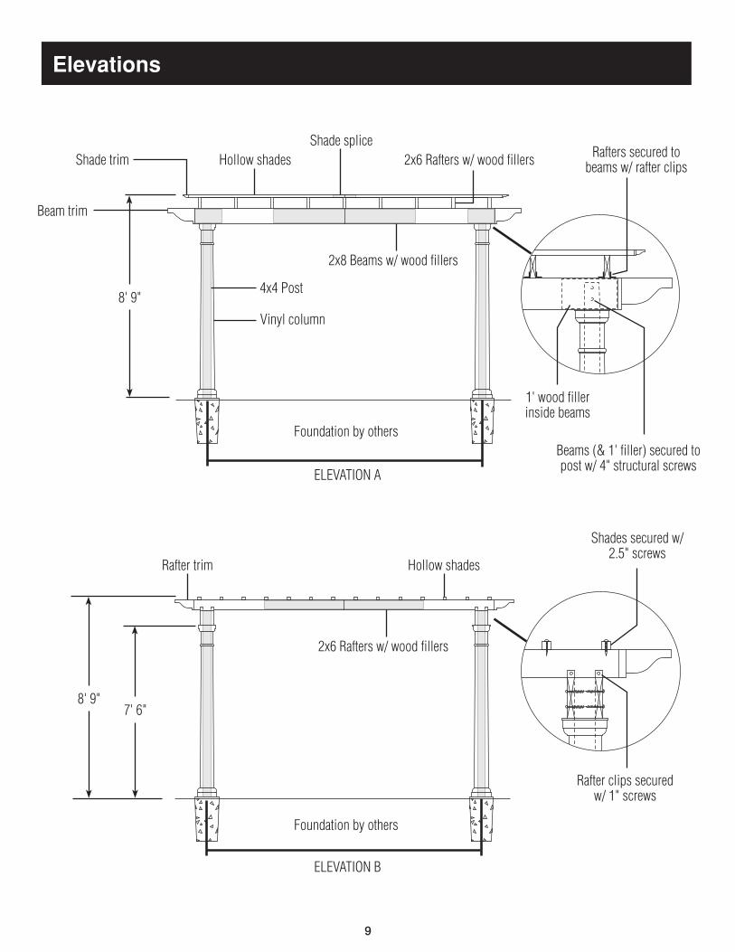
Elevations
ELEVATION A
ELEVATION B
Hollow shades
4x4 Post8' 9"
8' 9"7' 6"
Vinyl column
Foundation by others
Foundation by others
Beam trim
Shade trim 2x6 Rafters w/ wood fillers
2x8 Beams w/ wood fillers
Rafter trim Hollow shades
Shade splice
1' wood fillerinside beams
2x6 Rafters w/ wood fillers
Shades secured w/2.5" screws
Rafter clips securedw/ 1" screws
Rafters secured tobeams w/ rafter clips
Beams (& 1' filler) secured topost w/ 4" structural screws

10
Thepostwiththehigh-windbracketshouldlookaspictured.
Attachthehigh-windbracket(C)usingthescrewsthatwereremovedinStep1.Thehigh-windbracketusesanadditional14screwsthatareincluded.
3
CA
Slidethehigh-windbracket(C)ontothebottomofthepost(A),makingsurethatitissnugagainstthebottom.
2
C
A
Ifyouhavechosentopurchasethehigh-windbrackets(C),removethescrewsintheexistingbrackets(B).Setbracketsasideandsaveallscrewsforlater.
x10
1 B
A
Optional High-Wind Bracket Pre-assembly
11
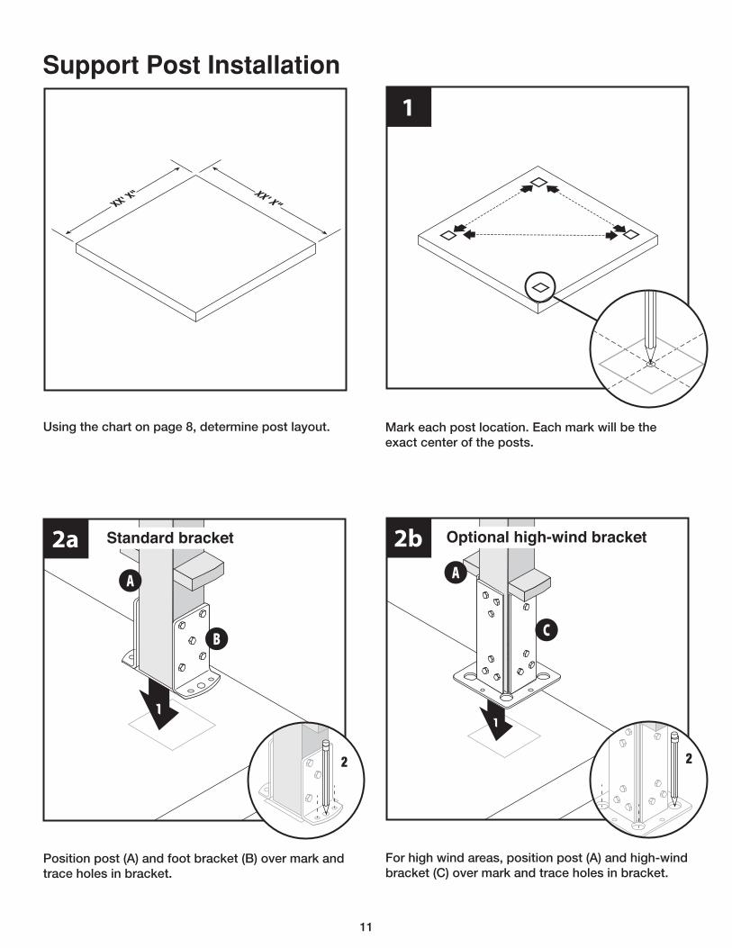
Markeachpostlocation.Eachmarkwillbethe exactcenteroftheposts.
1
Positionpost(A)andfootbracket(B)overmarkandtraceholesinbracket.
2a Standard bracket
B
A
1
2
Forhighwindareas,positionpost(A)andhigh-windbracket(C)overmarkandtraceholesinbracket.
1
2b Optional high-wind bracket
2
C
A
Support Post Installation
Usingthechartonpage8,determinepostlayout.
XX' X" XX' X"
35
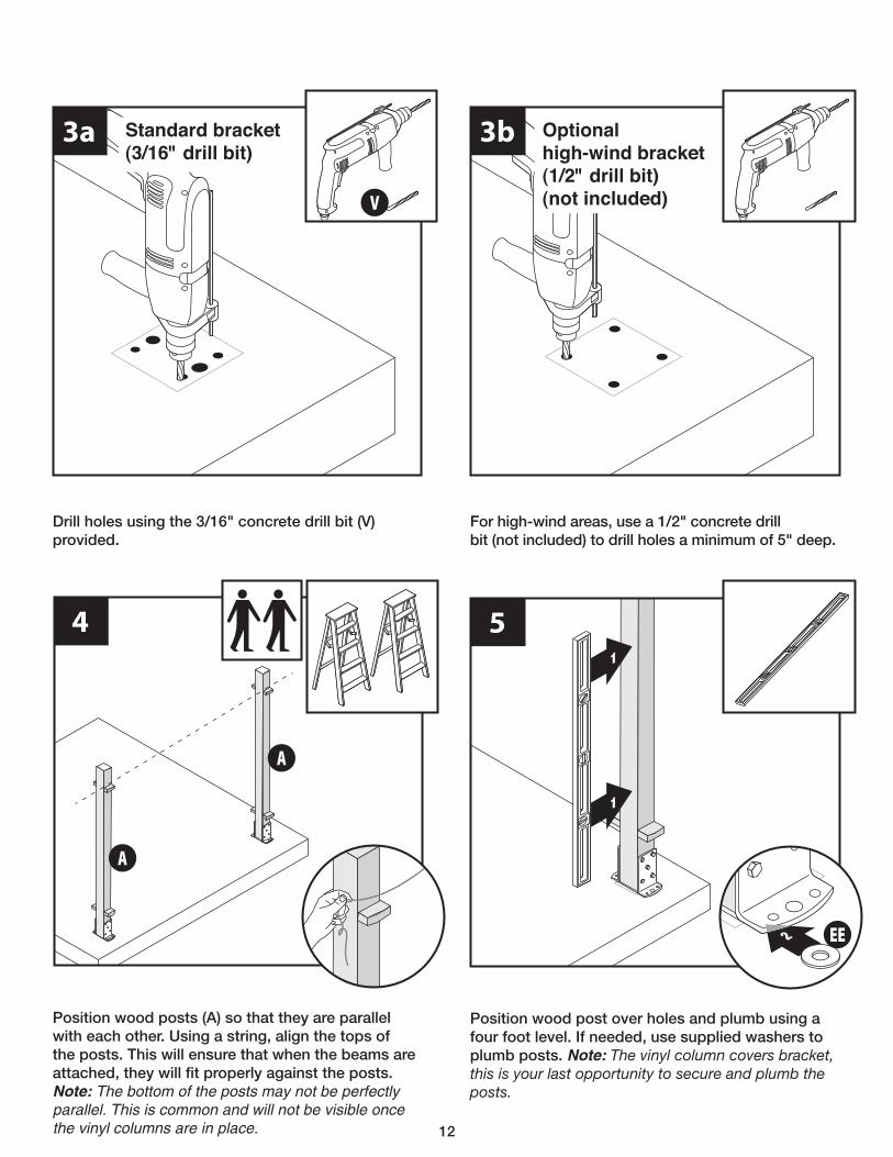
12
Optional high-wind bracket (1/2" drill bit)(not included)
3b
4
A
A
51
1
2 EE
Drillholesusingthe3/16"concretedrillbit(V) provided.
Forhigh-windareas,usea1/2"concretedrill bit(notincluded)todrillholesaminimumof5"deep.
Positionwoodposts(A)sothattheyareparallelwitheachother.Usingastring,alignthetopsoftheposts.Thiswillensurethatwhenthebeamsareattached,theywillfitproperlyagainsttheposts.Note: The bottom of the posts may not be perfectly parallel. This is common and will not be visible once the vinyl columns are in place.
Positionwoodpostoverholesandplumbusingafourfootlevel.Ifneeded,usesuppliedwasherstoplumbposts.Note: The vinyl column covers bracket, this is your last opportunity to secure and plumb the posts.
3a (3/16" drill bit)Standard bracket(3/16" drill bit)
V

13
Usefourconcretescrews(Z)tosecure.Tightensecurely.Do notproceedwithpostcoversuntil allwoodpostsareplumbandmountedsecurely.
x4
6c Optional high-wind bracket
AA Repeat Steps 2-6for remaining posts.
7
Useconcretescrews/bolts(AA)tosecurebrackets.Tightensecurely.Do notproceedwithpostcoversuntilallwoodpostsareplumbandmountedsecurely.
Asanoption,additional1/2"x4"concretescrews/bolts(AA)canbeinstalled.
6a
x4
Z
x2
6b Optional bolts
AA
14
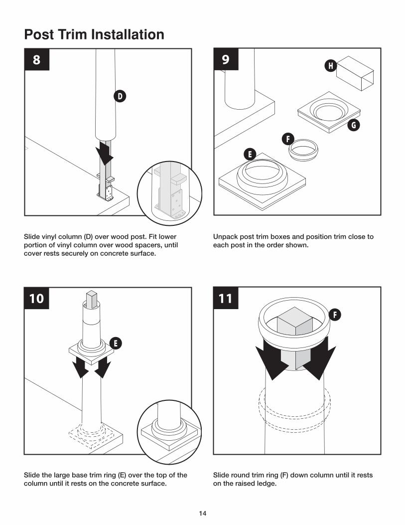
Slidethelargebasetrimring(E)overthetopofthecolumnuntilitrestsontheconcretesurface.
Slideroundtrimring(F)downcolumnuntilitrestsontheraisedledge.
Slidevinylcolumn(D)overwoodpost.Fitlower portionofvinylcolumnoverwoodspacers,untilcoverrestssecurelyonconcretesurface.
10
E
11F
Unpackposttrimboxesandpositiontrimclosetoeachpostintheordershown.
9
E
G
F
H8
D
Post Trim Installation

15
Slidetopsquarepostsleeve(H)overwoodpost.
Repeat Steps 10-13for remaining posts.
14
Slidetoptrimring(G)overcolumn,makingsuretheroundedpartisfacingdownandthesquarepartisfacingup.
Thisishowthetopposttrimshouldlook.
13H
12G

16
Hooktemporarybeamholder(BB)ontopofthesquarepostsleeve,facingdirectionofpost,whichwillbesupportingtheoppositeendofthebeam.Repeatforoppositepost.
16CC
DD
1
2
2
Thisishowthetemporarybeamholdershouldlookwhenitispositionedtoholdthebeamduringbeaminstallation.
Insertwoodblock(CC),makingsurethetwoholesinthewoodblockarefacingupward.Insertawoodpeg(DD)ineachhole.Repeatforoppositepost.
15
BB
17
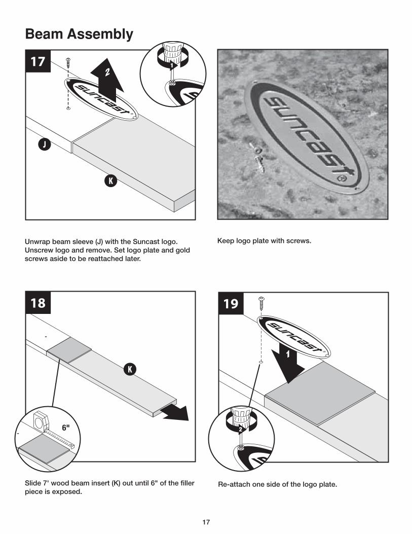
Slide7'woodbeaminsert(K)outuntil6"ofthefillerpieceisexposed.
2
19
1
Re-attachonesideofthelogoplate.
6"
18
K
Keeplogoplatewithscrews.
1172
J
K
Unwrapbeamsleeve(J)withtheSuncastlogo.Unscrewlogoandremove.Setlogoplateandgoldscrewsasidetobereattachedlater.
Beam Assembly

18
21
1/4"
23 L
L
J
J
3"3"
x2
22 X
X
Measure3"fromthespliceonbothsides.Fastentwo1"screws(X)onthetopofbothbeams.
Measuretheplacementoftheexistingscrewinthelogoplateandtransferthemeasurementtotheotherendofthelogoplate.Insertandtightenremainingscrew.
Unpack1'woodbeaminserts(L).Slidewoodbeaminsertintohollowendsofbeamsleeve(J). Woodbeaminsertshouldbeflushwithendor recessed1/4".
20
1
2
J
Slipoppositebeamsleeve(J)overwoodbeam insert.Liftlogoplatewhileslidingbeamsleeveunderneath.Theseamshouldbesnugwheretwosleevesmeet.

19
25 7 1/4"
Measureandmarkaline71/4"infromtheendofbeam.Repeatonotherendofbeam.Note: Bottom edge of beam is determined by the logo plate orientation.
Repeat Steps 17-26for remaining beams.
275"
1 1/2"
26
U
Measureandmarkholes5"and11/2"frombottomofbeam.Predrillholesmakingsurethattheholethatis11/2"fromtheedgeistowardsthebottomofthebeam.
24 6"X
Fastena1"screw(X)onthetopedgeofbeam, 6"fromtheendofthebeam.Note: Top edge of beam is determined by the logo plate orientation.
20
29
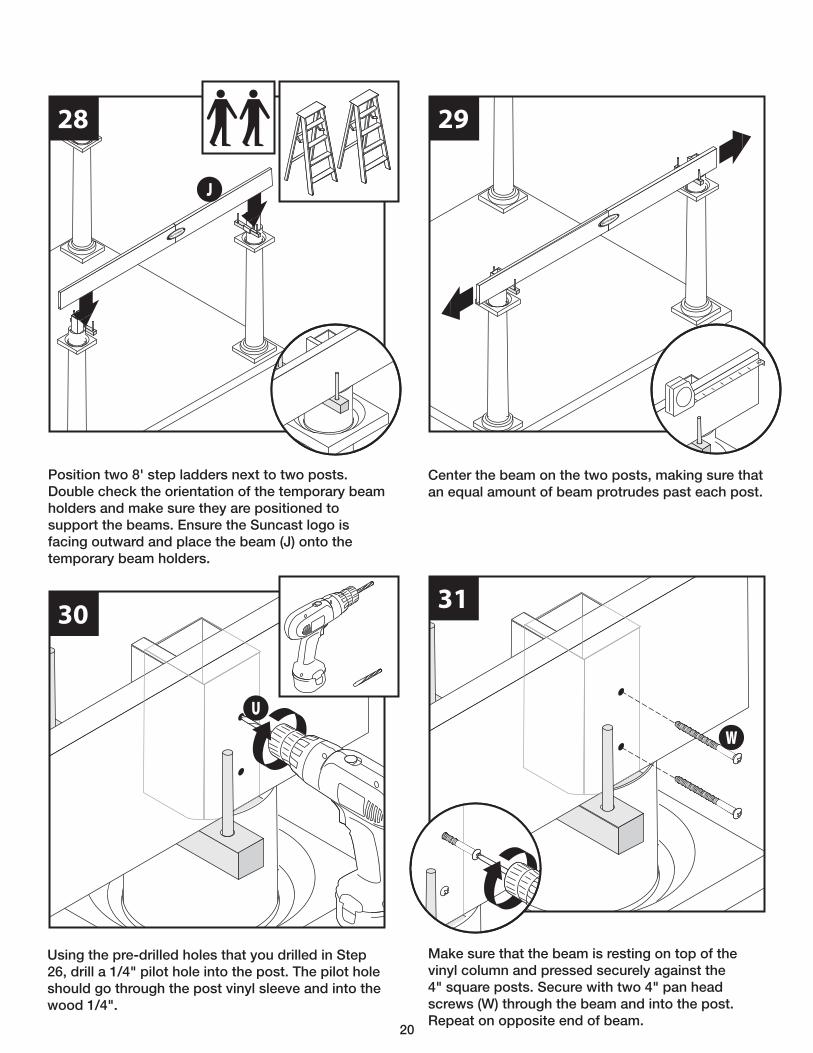
Centerthebeamonthetwoposts,makingsurethatanequalamountofbeamprotrudespasteachpost.
Usingthepre-drilledholesthatyoudrilledinStep26,drilla1/4"pilotholeintothepost.Thepilotholeshouldgothroughthepostvinylsleeveandintothewood1/4".
30
U
31
W
Makesurethatthebeamisrestingontopofthevinylcolumnandpressedsecurelyagainstthe 4"squareposts.Securewithtwo4"panheadscrews(W)throughthebeamandintothepost.Repeatonoppositeendofbeam.
28
J
Positiontwo8'stepladdersnexttotwoposts.Doublechecktheorientationofthetemporarybeam holdersandmakesuretheyarepositionedto supportthebeams.EnsuretheSuncastlogois facingoutwardandplacethebeam(J)ontothe temporarybeamholders.

21
Repeat steps 28-31to install opposite
beam.
33 34
DD
CC
BB
1
23
1
Removewoodpegs(DD)andslideoutwoodblocks(CC)toremovetemporarybeamholders(BB). Reinstallthem,asneeded,onremainingposts.
32
J
Positionnextassembledbeam(J)onoppositesideofpost.Makesurethepre-drilledholesarefacingoutwardandtowardsthebottom.
Theinstalledbeamshouldlooklikethis.
22
2
1 1/4"37
1
FF
X
1
X2
38FF 1 1/4"
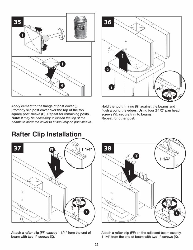
Attacharafterclip(FF)ontheadjacentbeamexactly11/4"fromtheendofbeamwithtwo1"screws(X).
x4
36
1
Y
G
2
Holdthetoptrimring(G)againstthebeamsand flusharoundtheedges.Usingfour21/2"panheadscrews(Y),securetrimtobeams. Repeatforotherpost.
Attacharafterclip(FF)exactly11/4"fromtheendofbeamwithtwo1"screws(X).
Rafter Clip Installation
35
I
I
H
Applycementtotheflangeofpostcover(I).Promptlyslippostcoveroverthetopofthetopsquarepostsleeve(H).Repeatforremainingposts.Note: It may be necessary to loosen the top of the beams to allow the cover to fit securely on post sleeve.

23
2
41FF
X
11
Installremainingrafterclips(FF)usingtwo 1"screws(X)oneachclip.
X
X
X
X
X
40
Refertothecharttodeterminerafterclipspacing.Usingatapemeasureandpencil,markthelocationofrafterclips.
Pergola Size Rafter Spacing(on center)
Number of Rafters
8x8 16 3/4" 6
8x12 16" 9
10x14 19" 9
10x16 17 3/8" 11
12x16 17 3/8" 11
14x14 19" 9
14x20 19 1/4" 13
Attacharafterclip(FF)directlyoverthetopofthe beamspliceinthecenterofeachbeamwithtwo 1"screws(X).
2
39FF
X
11
24
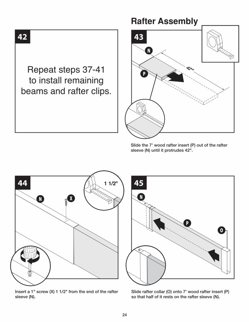
Inserta1"screw(X)11/2"fromtheendoftheraftersleeve(N).
45
OP
N
Slideraftercollar(O)onto7'woodrafterinsert(P)sothathalfofitrestsontheraftersleeve(N).
1 1/2"44
XN
42"
43
N
P
Slidethe7'woodrafterinsert(P)outoftheraftersleeve(N)untilitprotrudes42".
Rafter Assembly
Repeat steps 37-41to install remaining
beams and rafter clips.
42

25
Positiontwostepladdersnexttotwoposts. Placeeachendofarafter(N)intotheoutermostrafterclipsonthebeams.
N
4948
Atthispointintheassemblyprocess,alloftheposts,beams,andrafterclipsshouldbe permanentlyinstalled.Alloftheraftersshouldbeassembledandreadytobeinstalled.
Repeat steps 43-46to assemble remaining
rafters.
47
Installing the Rafters
46
X
N
P
1
1
2
Slideraftersleeve(N)over7'woodrafterinsert(P)untilthetwovinylsleevesaretouching.Inserta 1"screw(X)nexttothecollar.

26
53N
Placeeachendofarafter(N)intotheoutermostclipsonthebeams.
Usingfour1"screws(X),secureraftertotherafterclips.
52
X
x4
Usingfour1"screws(X),secureraftertotherafterclipsonoppositeendofbeam.
51
X
x4
Centertherafteronthebeams,bymeasuringfromeachendoftheraftertotheoutsideedgeofthebeam.Bothofthemeasurementsoneachsideofthebeamshouldbeequal.
50

27
4"
55
56
Afterraftershavebeeninstalledthepergolashouldlooklikethis.
Positiontheremainingrafters,fittingtheminsidetherafterclips.DO NOTattachany,untilallhavebeencenteredandpositioned.Adjusttheraftersas needed,makesureallrafterslineupperfectlystraightbeforesecuringtorafterclips.
Beforemovingon,measurethebeamsattheseamtomakesurethespacingbetweenthebeamsis4".Ifneeded,temporarilyinserta4"spacerwhileattachingremainingrafters.
Repeat steps 49-52to center rafter and
secure rafter torafter clips.
54
28
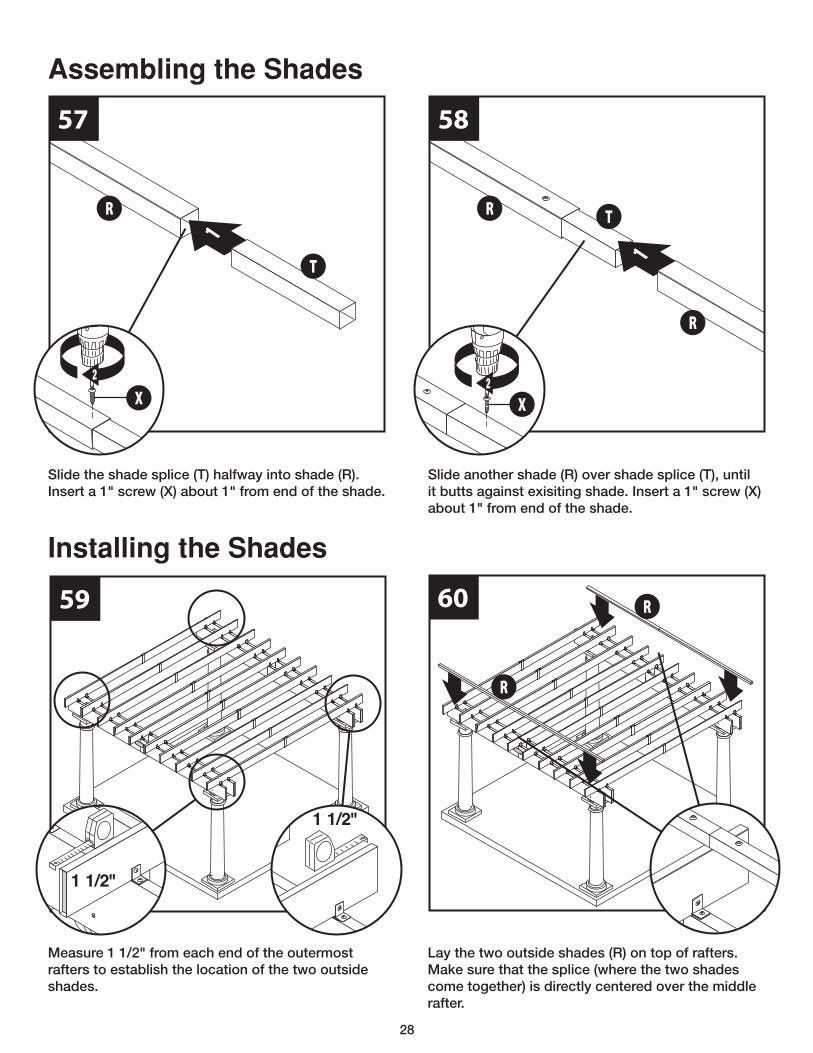
Measure11/2"fromeachendoftheoutermostrafterstoestablishthelocationofthetwooutsideshades.
Laythetwooutsideshades(R)ontopofrafters.Makesurethatthesplice(wherethetwoshadescometogether)isdirectlycenteredoverthemiddlerafter.
59
1 1/2"
1 1/2"
60 R
R
Slideanothershade(R)overshadesplice(T),untilitbuttsagainstexisitingshade.Inserta1"screw(X)about1"fromendoftheshade.
2
58
TR
R
X
1
Slidetheshadesplice(T)halfwayintoshade(R).Inserta1"screw(X)about1"fromendoftheshade.
57
T
R
X2
1
Assembling the Shades
Installing the Shades

29
12 1/8"
12 1/8"12 1/8"
12 1/8" 12 1/8"X
X
61
Measureandmarkrafters121/8"fromthecenterofthefirstshadeforremainingshades.
Priortofasteningtheshades,sighttheraftersandstraightenshadesasneeded.
62
Y
Afterpositioningtheshades,beginatthecornerandfastenshadesusing21/2"panheadscrews(Y).Ensurescrewsgothroughthetopoftheshadeandintotherafter.
Secure remainingshades to rafters.
63

30
64M
M
65Q
Q
Applycementtoinsideringofraftertrim(Q).Promptlytapraftertrimintoplace,sothattrimissnugandlevel.Repeatforremainingrafters.
Applycementtoinsideringofbeamtrim(M).Promptlytapbeamtrimintoplace,sothattrimissnugandlevel.Repeatforremainingbeams.
Multi-purposecementisprovidedtoinstall decorativetrim.
Installing Decorative Trim
Applycementtoinsideringofshadetrim(S).Promptlytapshadetrimintoplace,sothattrimissnugandlevel.Repeatforremainingshades.
66 S
S

31
67
X Ex2
Makesurethatthelargebasetrimring(E)issquareandparalleltothebeam.Securetrimwithtwo1"screws(X)onoppositesidesoftheposts.Repeatforremainingposts.
Afterbeam,rafter,andshadetrimhavebeen installed,thepergolashouldlooklikethis.
Congratulations!Yourpergolaisnowreadytoenjoy.

Suncast®Corporation,701NorthKirkRoad,Batavia,Illinois60510(Manufacturer)warrantstotheoriginalpurchaseronlythattheenclosedproductisfreefrommaterialandworkmanshipdefectsundernormal,house-holduseattimeofpurchase.Defectiveproductorpartmustbereturned,freightprepaid,totheManufacturer'saddress(Attention:PartsDepartment)alongwithproofofpurchase.Uponreceiptoftheaforesaid,thedefec-tiveproductorpartwillberepairedorreplacedattheoptionoftheManufacturerwithoutchargetotheoriginalpurchaserandreturnedtothecustomerfreightcollect.
Thislimitedwarrantydoesnotapplytodamageresultingfromaccident,neglect,misuse,commercialuse,al-teration,operationnotinaccordancewithinstructionorrepairsmadeorattemptedbyunauthorizedpersons.
Thislimitedwarrantyappliesonlytotheproductenclosedanddoesnotapplytoaccessoryparts.
THEMANUFACTURER'SLIABILITYHEREUNDERISLIMITEDSOLELYTOTHEREPAIRORREPLACEMENTOFTHEDEFECTIVEPRODUCTORPARTANDTHEMANUFACTURERSHALLINNOEVENTBELIABLEFORANYINCIDENTALORCONSEQUENTIALDAMAGESWHICHMAYRESULTFROMANYDEFECTINMATERIALORWORKMANSHIPORFROMTHEBREACHOFANYEXPRESSORIMPLIEDWARRANTY.
Somestatesdonotallowtheexclusionorlimitationofincidentalorconsequentialdamages,oralimitationofhowlonganimpliedwarrantylasts,sotheabovelimitationsmaynotapplytoyou.Thiswarrantygivesyouspe-cificlegalrights,andyoumayhaveotherrightswhichmayvaryfromstatetostate.
Repairserviceandassemblyassistanceareavailabledirectfromthefactory,notfromtheplaceofpurchase.Ifthisproductrequiresrepair,pleasecallorwriteus.Warrantyrepairpartsaresentoutfreeofcharge.Iftheprod-uctisoutofwarranty,wewillinformyouofthechargespriortosendingouttheparts.VISAandMasterCardareacceptedonphoneorders.TopurchaseSuncastreplacementpartsandlearnmoreaboutotherSuncastproducts,visitusonlineatwww.suncast.com24hoursaday,7daysaweek,365daysayear,orcall 1-800-844-3310Mon-Fri6am-8pmCST.
Warranty
Factory Repairs