freelander owner's handbook - eng...emergency starting 121 using booster cables using booster...
TRANSCRIPT
Emergency Starting
121
USING BOOSTER CABLESUsing booster cables (jump leads) from a donor battery, or abattery fitted to a donor vehicle, is the only approved method ofstarting a vehicle with a flat battery. Push or tow starting is NOTrecommended!
1. If a donor vehicle is to be used, the vehicles should be parkedwith their battery locations adjacent to one another. Ensure thatthe two vehicles do not touch.
2. Apply the handbrakes and ensure that the gear levers on bothvehicles are in neutral (’P’ - Park for vehicles with automatictransmission).
3. Turn off the starter switch and ALL electrical equipment ofBOTH vehicles.
4. Connect the RED booster cable between the positive (+)terminals of both batteries.
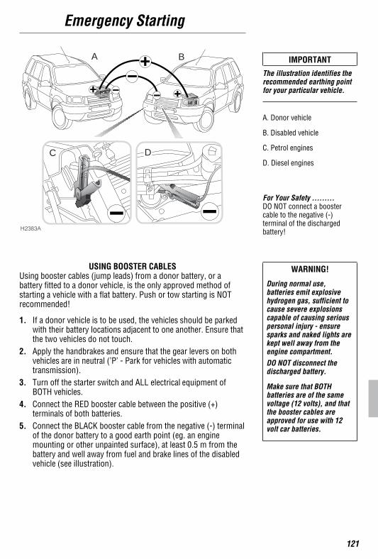
5. Connect the BLACK booster cable from the negative (-) terminalof the donor battery to a good earth point (eg. an enginemounting or other unpainted surface), at least 0.5 m from thebattery and well away from fuel and brake lines of the disabledvehicle (see illustration).
IMPORTANT
The illustration identifies therecommended earthing pointfor your particular vehicle.
A. Donor vehicle
B. Disabled vehicle
C. Petrol engines
D. Diesel engines
For Your Safety .........DO NOT connect a boostercable to the negative (-)terminal of the dischargedbattery!
WARNING!
During normal use,batteries emit explosivehydrogen gas, sufficient tocause severe explosionscapable of causing seriouspersonal injury - ensuresparks and naked lights arekept well away from theengine compartment.DO NOT disconnect thedischarged battery.
Make sure that BOTHbatteries are of the samevoltage (12 volts), and thatthe booster cables areapproved for use with 12volt car batteries.
H2383A
C D
BA
Emergency Starting
122
6. Check that the cables are clear of moving parts of both engines,then start the engine of the donor vehicle and allow it to idle fora few minutes.
7. Now start the engine of the vehicle with the discharged battery(DO NOT crank the engine for more than 15 seconds).
8. Once both engines are running normally, allow them to idle fortwo minutes before switching off the engine of the donorvehicle and disconnecting the booster cables. DO NOT switchon any electrical circuits on the previously disabled vehicle, untilAFTER the booster cables have been removed.
9. Disconnecting the booster cables must be an exact reversal ofthe procedure used to connect them, ie: disconnect the BLACKcable from the earth point on the disabled vehicle FIRST.
Vehicle Recovery
123
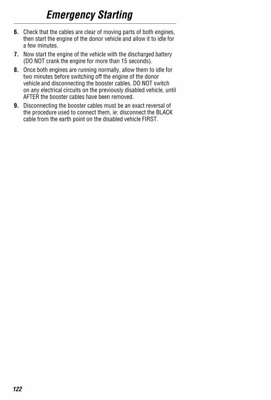
VEHICLE RECOVERYThe recommended method of transporting your vehicle is by meansof a trailer or vehicle transporter.
Lashing rings are provided at the front and rear of the vehicle,where shown in the illustration.
Suspended towIf it is necessary to tow your vehicle on two wheels (ie: suspendedfrom a recovery vehicle), it is essential that the propellor shaftconnected to the axle that is to remain on the ground isdisconnected by qualified personnel, prior to being towed.
WARNING!
The lashing rings are forlashing only and must NOTbe used for towing.
Care Points .........DO NOT secure lashing hooksor trailer fixings to any otherpart of the vehicle.
Do not tow the vehicle on twowheels without disconnectingthe appropriate propellor shaft.
Under no circumstances shouldthe vehicle be towed orrecovered by lashing to the rearsubframe. Serious damage tothe subframe and body mayoccur.
H2405

Vehicle Recovery
124
Front towing eyeUse ONLY when the vehicle is to be towed with all four wheels onthe ground.
Rear towing eyeUse ONLY when towing another vehicle.
Towing the vehicle on four wheelsIf it is necessary to tow the vehicle on four wheels;
• Turn the starter key to position ’I’ to unlock the steering andthen to position ’II’ to enable the brake lights, wipers anddirection indicators to be operated, if necessary.
• Place the gear lever in neutral.
• Release the handbrake.
WARNING!
DO NOT remove the starterkey or tun the starter switchto position ’0’ while thevehicle is in motion.
For Your Safety .........Without the engine running,greater effort will be required tooperate the brake pedal andlonger stopping distances willbe experienced.If, due to an accident orelectrical fault, it is consideredunsafe to turn the starterswitch to position ’I’,disconnect the battery beforeturning the switch.
For Your Safety .........While towing, do not exceed 30mph (45 km/h).
H2334A
H2335A
Wheel Changing
125
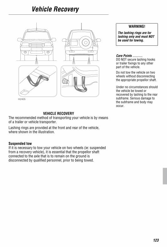
The tool kit, containing the chock, jacking tools and wheel nutspanner is stowed in the engine compartment.
For Your Safety .........Tools stowed in the enginecompartment will be hot if theengine has been running.
Operating Tip ..........The chock is designed to foldaway and must be assembledas in the illustration before use.
H2368B
H2363A
Wheel Changing
126
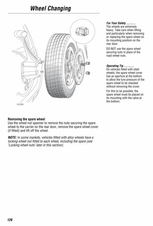
Removing the spare wheelUse the wheel nut spanner to remove the nuts securing the sparewheel to the carrier on the rear door, remove the spare wheel cover(if fitted) and lift off the wheel.
NOTE: In some markets, vehicles fitted with alloy wheels have alocking wheel nut fitted to each wheel, including the spare (see’Locking wheel nuts’ later in this section).
For Your Safety .........The wheels are extremelyheavy. Take care when liftingand particularly when removingor replacing the spare wheel onits mounting position on therear door.
DO NOT use the spare wheelsecuring nuts in place of theroad wheel nuts.
Operating Tip ..........On vehicles fitted with steelwheels, the spare wheel coverhas an aperture at the bottomto allow the tyre pressure of thespare wheel to be checkedwithout removing the cover.For this to be possible, thespare wheel must be placed onits mounting with the valve atthe bottom.
H2399
Wheel Changing
127
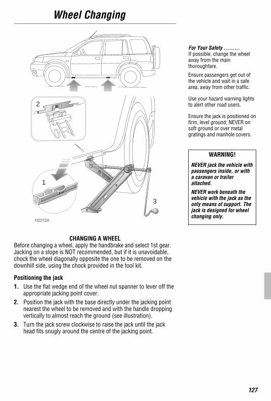
CHANGING A WHEELBefore changing a wheel, apply the handbrake and select 1st gear.Jacking on a slope is NOT recommended, but if it is unavoidable,chock the wheel diagonally opposite the one to be removed on thedownhill side, using the chock provided in the tool kit.
Positioning the jack1. Use the flat wedge end of the wheel nut spanner to lever off the
appropriate jacking point cover.2. Position the jack with the base directly under the jacking point
nearest the wheel to be removed and with the handle droppingvertically to almost reach the ground (see illustration).
3. Turn the jack screw clockwise to raise the jack until the jackhead fits snugly around the centre of the jacking point.
For Your Safety .........If possible, change the wheelaway from the mainthoroughfare.
Ensure passengers get out ofthe vehicle and wait in a safearea, away from other traffic.
Use your hazard warning lightsto alert other road users.
Ensure the jack is positioned onfirm, level ground; NEVER onsoft ground or over metalgratings and manhole covers.
WARNING!
NEVER jack the vehicle withpassengers inside, or witha caravan or trailerattached.
NEVER work beneath thevehicle with the jack as theonly means of support. Thejack is designed for wheelchanging only.
H2372A
1
2
3
Wheel Changing
128
Changing the wheel
• Before raising the vehicle, use the wheel nut spanner to slackeneach of the wheel nuts half a turn.
• Turn the jack handle clockwise to raise the vehicle until the tyreis clear of the ground. Remove the wheel nuts and wheel.
• On alloy wheels, use an approved anti-seize compound to treatthe wheel mounting spigot, to minimise the tendency foradhesion between wheel and the spigot. Ensure that no oil orcompound comes into contact with the brake components orthe wheel nut threads. If, due to an emergency situation, thistreatment is not practicable, refit the spare wheel for the timebeing and treat the wheel at the earliest opportunity.
• Fit the spare wheel and tighten the wheel nuts (domed sidetowards the wheel) until the wheel is firmly seated against thehub.
• Lower the vehicle and remove the jack and wheel chock, thenFULLY tighten the wheel nuts in alternate sequence with thewheel nut spanner provided. Have the wheel nut torque checkedat the earliest opportunity.
• Refit the jacking point cover
• Refit the wheel nut cover (on steel wheels) , then remount thereplaced wheel and the spare wheel cover (if fitted) on thetaildoor.
• Finally, return the tools to their bag and strap the bag into itscradle in the engine compartment.
Operating Tip ..........On vehicles fitted with steelwheels, use the flat, wedgeshaped end of the wheel nutspanner to lever off the wheelnut cover
For Your Safety .........Avoid contact with a hotexhaust system.
After changing a wheel, havethe tyre pressure and wheel nuttorque checked as soon aspossible.
Care Points .........Avoid placing wheels facedown on the ground. This mayscratch the surface.

Wheel Changing
129
LOCKING WHEEL NUTSOne locking wheel nut is fitted to each alloy road wheel (includingthe spare). Locking wheel nuts are visually similar to standardwheel nuts, but can only be removed using the special toolsprovided, as follows:
Push the extractor (1) firmly over the head of the locking wheel nut.Pull to remove the nut cover (2).
Fit the key socket (3) over the locking wheel nut (4) then, using thewheel nut spanner, undo the nut in the normal way.
NOTE: The key socket can be retained inside the extractor tubewhen not in use. Both extractor tube and key socket can be kept inthe pocket of the toolkit bag.
IMPORTANT
A code number is stamped onthe face of the socket. Ensurethe number is recorded on theSecurity Information cardsupplied with the literaturepack. Quote this number ifreplacements are required.For security reasons, DO NOTkeep the card in the vehicle.
H2396A
12
4 3
Fuses
130
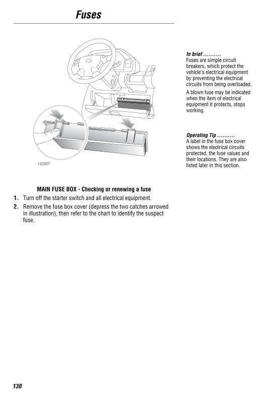
MAIN FUSE BOX - Checking or renewing a fuse1. Turn off the starter switch and all electrical equipment.2. Remove the fuse box cover (depress the two catches arrowed
in illustration), then refer to the chart to identify the suspectfuse.
In brief ..........Fuses are simple circuitbreakers, which protect thevehicle’s electrical equipmentby preventing the electricalcircuits from being overloaded.A blown fuse may be indicatedwhen the item of electricalequipment it protects, stopsworking.
Operating Tip ..........A label in the fuse box covershows the electrical circuitsprotected, the fuse values andtheir locations. They are alsolisted later in this section.H2307
Fuses
131
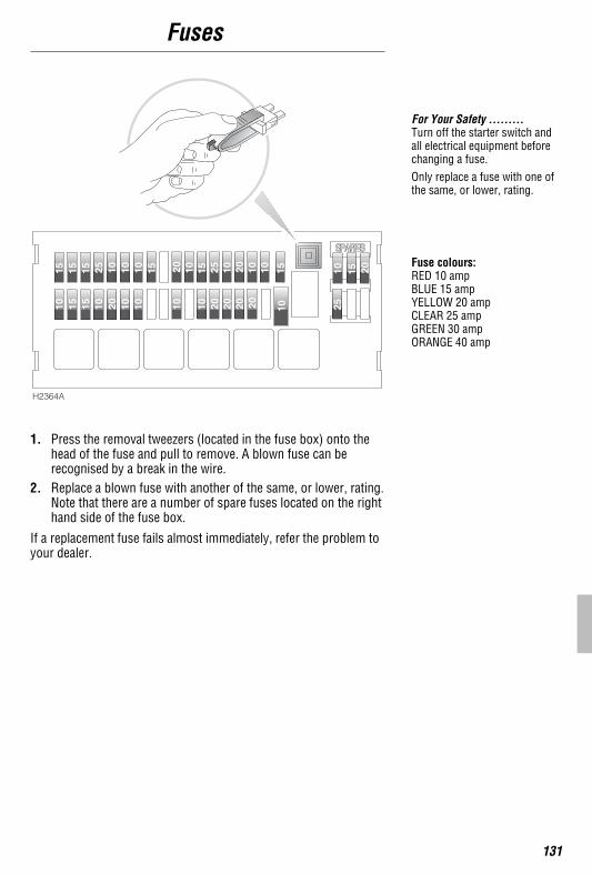
1. Press the removal tweezers (located in the fuse box) onto thehead of the fuse and pull to remove. A blown fuse can berecognised by a break in the wire.
2. Replace a blown fuse with another of the same, or lower, rating.Note that there are a number of spare fuses located on the righthand side of the fuse box.
If a replacement fuse fails almost immediately, refer the problem toyour dealer.
For Your Safety .........Turn off the starter switch andall electrical equipment beforechanging a fuse.Only replace a fuse with one ofthe same, or lower, rating.
Fuse colours:RED 10 ampBLUE 15 ampYELLOW 20 ampCLEAR 25 ampGREEN 30 ampORANGE 40 amp
H2364A
Fuses
132
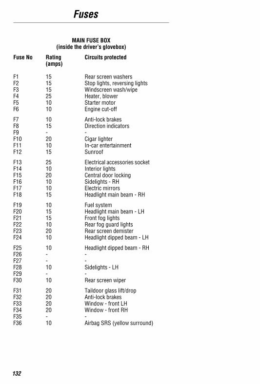
MAIN FUSE BOX(inside the driver’s glovebox)
Fuse No Rating(amps)
Circuits protected
F1 15 Rear screen washersF2 15 Stop lights, reversing lightsF3 15 Windscreen wash/wipeF4 25 Heater, blowerF5 10 Starter motorF6 10 Engine cut-off
F7 10 Anti-lock brakesF8 15 Direction indicatorsF9 - -F10 20 Cigar lighterF11 10 In-car entertainmentF12 15 Sunroof
F13 25 Electrical accessories socketF14 10 Interior lightsF15 20 Central door lockingF16 10 Sidelights - RHF17 10 Electric mirrorsF18 15 Headlight main beam - RH
F19 10 Fuel systemF20 15 Headlight main beam - LHF21 15 Front fog lightsF22 10 Rear fog guard lightsF23 20 Rear screen demisterF24 10 Headlight dipped beam - LH
F25 10 Headlight dipped beam - RHF26 - -F27 - -F28 10 Sidelights - LHF29 - -F30 10 Rear screen wiper
F31 20 Taildoor glass lift/dropF32 20 Anti-lock brakesF33 20 Window - front LHF34 20 Window - front RHF35 - -F36 10 Airbag SRS (yellow surround)
Fuses
133
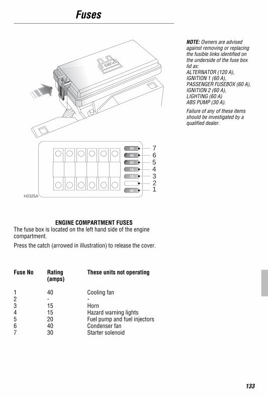
ENGINE COMPARTMENT FUSESThe fuse box is located on the left hand side of the enginecompartment.
Press the catch (arrowed in illustration) to release the cover.
Fuse No Rating(amps)
These units not operating
1 40 Cooling fan2 - -3 15 Horn4 15 Hazard warning lights5 20 Fuel pump and fuel injectors6 40 Condenser fan7 30 Starter solenoid
NOTE: Owners are advisedagainst removing or replacingthe fusible links identified onthe underside of the fuse boxlid as:ALTERNATOR (120 A),IGNITION 1 (60 A),PASSENGER FUSEBOX (60 A),IGNITION 2 (60 A),LIGHTING (60 A)ABS PUMP (30 A).
Failure of any of these itemsshould be investigated by aqualified dealer.
H2325A
7654321
Bulb Replacement
134
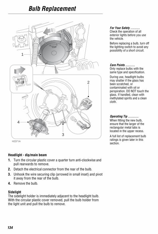
Headlight - dip/main beam1. Turn the circular plastic cover a quarter turn anti-clockwise and
pull rearwards to remove.2. Detach the electrical connector from the rear of the bulb.3. Unhook the wire securing clip (arrowed in small inset) and pivot
it away from the rear of the bulb.4. Remove the bulb.
SidelightThe sidelight holder is immediately adjacent to the headlight bulb.With the circular plastic cover removed, pull the bulb holder fromthe light unit and pull the bulb to remove.
For Your Safety .........Check the operation of allexterior lights before you usethe vehicle.Before replacing a bulb, turn offthe lighting switch to avoid anypossibility of a short circuit.
Care Points .........Only replace bulbs with thesame type and specification.During use, headlight bulbsmay shatter if the glass hasbeen scratched, orcontaminated with oil orperspiration. DO NOT touch theglass. If handled, clean withmethylated spirits and a cleancloth.
Operating Tip ..........When fitting the new bulb,ensure that the larger of therectangular metal tabs islocated in the upper recess.
A full list of replacement bulbratings is given later in thissection.
H2371A
1
2
3
4
Bulb Replacement
135
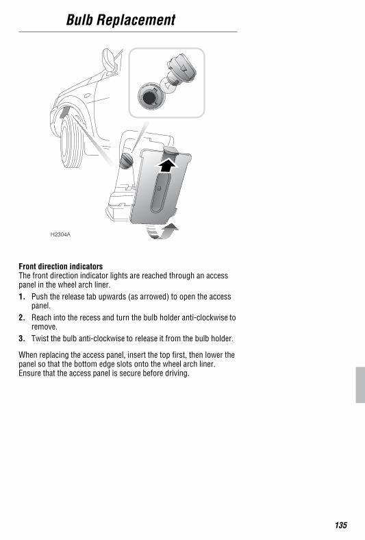
Front direction indicatorsThe front direction indicator lights are reached through an accesspanel in the wheel arch liner.1. Push the release tab upwards (as arrowed) to open the access
panel.2. Reach into the recess and turn the bulb holder anti-clockwise to
remove.3. Twist the bulb anti-clockwise to release it from the bulb holder.
When replacing the access panel, insert the top first, then lower thepanel so that the bottom edge slots onto the wheel arch liner.Ensure that the access panel is secure before driving.
H2304A
Bulb Replacement
136
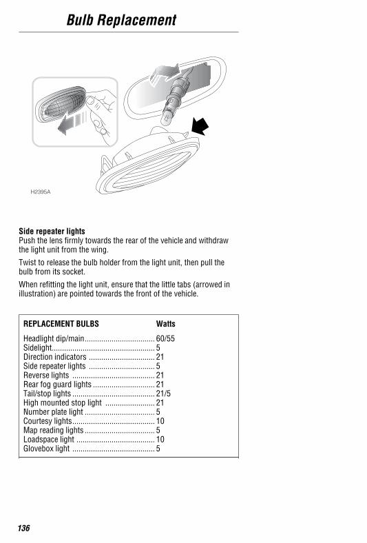
Side repeater lightsPush the lens firmly towards the rear of the vehicle and withdrawthe light unit from the wing.
Twist to release the bulb holder from the light unit, then pull thebulb from its socket.
When refitting the light unit, ensure that the little tabs (arrowed inillustration) are pointed towards the front of the vehicle.
REPLACEMENT BULBS Watts
Headlight dip/main 60/55..................................Sidelight 5..................................................Direction indicators 21................................Side repeater lights 5................................Reverse lights 21........................................Rear fog guard lights 21..............................Tail/stop lights 21/5........................................High mounted stop light 21........................Number plate light 5..................................Courtesy lights 10........................................Map reading lights 5..................................Loadspace light 10......................................Glovebox light 5........................................
H2395A
Bulb Replacement
137
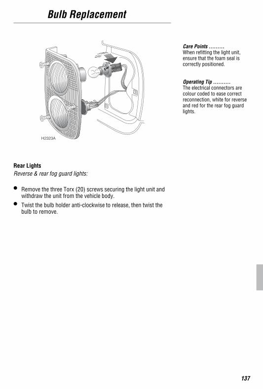
Rear LightsReverse & rear fog guard lights:
• Remove the three Torx (20) screws securing the light unit andwithdraw the unit from the vehicle body.
• Twist the bulb holder anti-clockwise to release, then twist thebulb to remove.
Care Points .........When refitting the light unit,ensure that the foam seal iscorrectly positioned.
Operating Tip ..........The electrical connectors arecolour coded to ease correctreconnection, white for reverseand red for the rear fog guardlights.
H2323A
Bulb Replacement
138
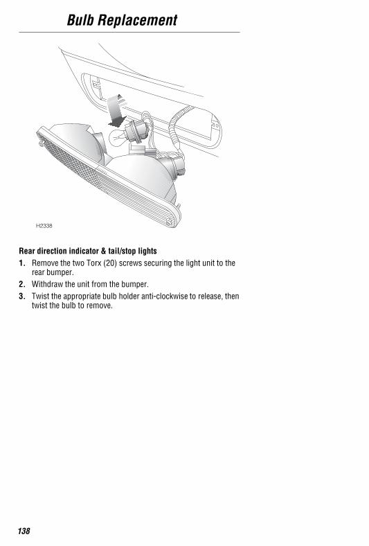
Rear direction indicator & tail/stop lights1. Remove the two Torx (20) screws securing the light unit to the
rear bumper.2. Withdraw the unit from the bumper.3. Twist the appropriate bulb holder anti-clockwise to release, then
twist the bulb to remove.
H2338
Bulb Replacement
139
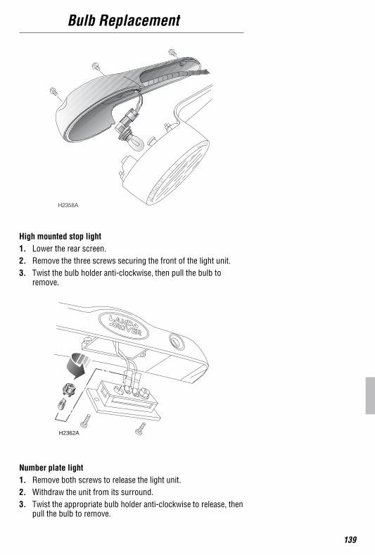
High mounted stop light1. Lower the rear screen.2. Remove the three screws securing the front of the light unit.3. Twist the bulb holder anti-clockwise, then pull the bulb to
remove.
Number plate light1. Remove both screws to release the light unit.2. Withdraw the unit from its surround.3. Twist the appropriate bulb holder anti-clockwise to release, then
pull the bulb to remove.
H2358A
H2362A
Bulb Replacement
140
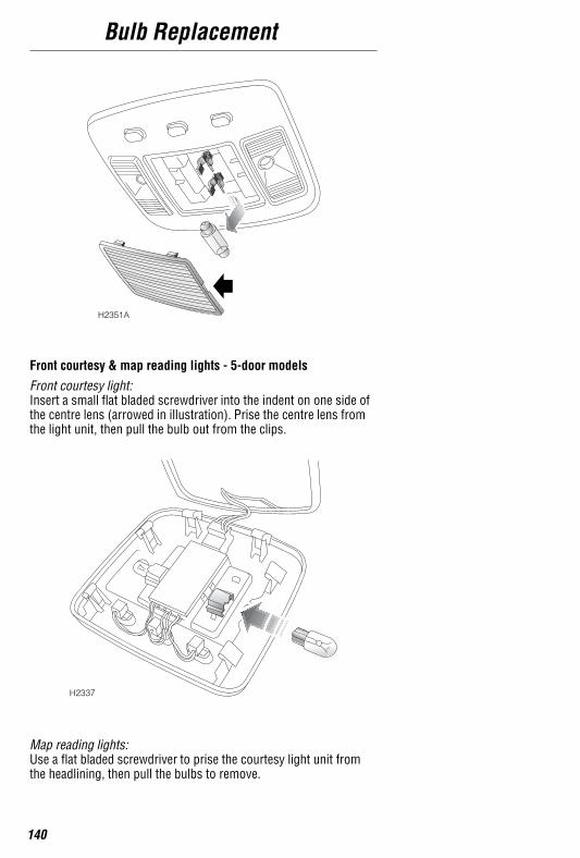
Front courtesy & map reading lights - 5-door models
Front courtesy light:Insert a small flat bladed screwdriver into the indent on one side ofthe centre lens (arrowed in illustration). Prise the centre lens fromthe light unit, then pull the bulb out from the clips.
Map reading lights:Use a flat bladed screwdriver to prise the courtesy light unit fromthe headlining, then pull the bulbs to remove.
H2351A
H2337
Bulb Replacement
141
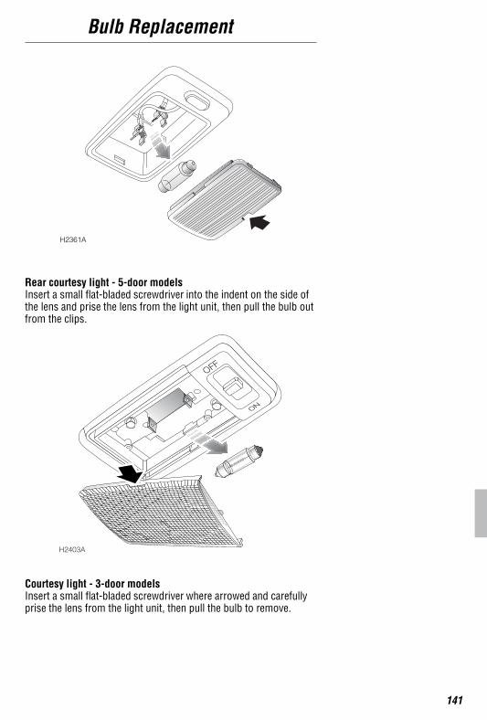
Rear courtesy light - 5-door modelsInsert a small flat-bladed screwdriver into the indent on the side ofthe lens and prise the lens from the light unit, then pull the bulb outfrom the clips.
Courtesy light - 3-door modelsInsert a small flat-bladed screwdriver where arrowed and carefullyprise the lens from the light unit, then pull the bulb to remove.
H2361A
H2403A
Bulb Replacement
142
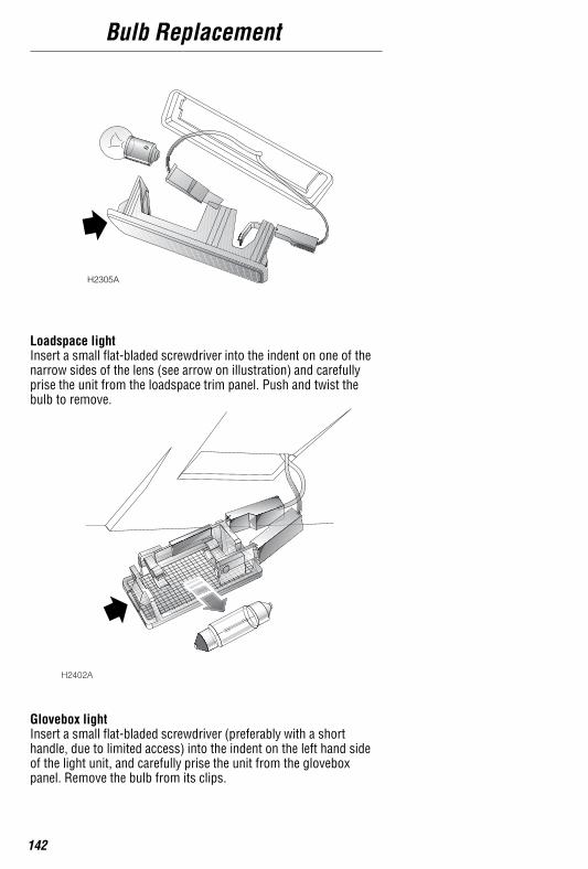
Loadspace lightInsert a small flat-bladed screwdriver into the indent on one of thenarrow sides of the lens (see arrow on illustration) and carefullyprise the unit from the loadspace trim panel. Push and twist thebulb to remove.
Glovebox lightInsert a small flat-bladed screwdriver (preferably with a shorthandle, due to limited access) into the indent on the left hand sideof the light unit, and carefully prise the unit from the gloveboxpanel. Remove the bulb from its clips.
H2305A
H2402A
Parts & Accessories
143
PARTS & ACCESSORIESYour vehicle has been designed, manufactured and proven to copewith rigorous driving conditions. As such, fitting parts andaccessories that have been developed and tested to the samestringent standards is essential to guarantee the continuedreliability, safety and performance of the vehicle.
To augment the vehicle’s ability, a comprehensive and versatilerange of spare parts and accessories are available to fulfill a widevariety of roles, both enhancing and protecting the vehicle in themany tasks to which it can be applied.
Genuine Land Rover parts are the ONLY parts built to originalequipment specifications AND approved by Land Rover designers;this means that every single part and accessory has been rigorouslytested by the same engineering team that designed and built thevehicle and can therefore be GUARANTEED for twelve months withUNLIMITED MILEAGE.
A full list and description of all accessories is available from yourLand Rover dealer.
Always consult a dealer for advice regarding the approval,suitability, installation and use of any parts or accessories beforefitting.
WARNING!
The fitting of parts andaccessories of inferiorquality, or carrying out ofnon-approved conversions,may be dangerous andcould affect the safety of thevehicle and occupants andinvalidate the terms andconditions of the vehiclewarranty.
For Your Safety .........It is extremely hazardous to fitparts or accessories whereinstallation requires thedismantling of, or addition to,either the electrical or fuelsystems.
An airbag SRS is fitted to yourvehicle, ALWAYS consult yourLand Rover dealer before fittingany accessory.
Parts & Accessories
144
After sales serviceThe After Sales Parts service is of paramount importance, both inthe UK and across the world. In the UK there are over 100authorised Land Rover dealers, all computer linked for rapidordering of parts and accessories.
In addition, with franchised representation in over 100 countriesworldwide, Land Rover are able to support your vehicle whereveryou go. A full list of Land Rover dealers is included in the literaturepack.
Only Land Rover dealers are able to provide the full range ofrecommended parts and accessories that meet our rigorousstandards of safety, durability and performance.
Travelling abroadIn certain countries, it is illegal to fit parts which have not beenmade to the vehicle manufacturer’s specification.
Owners should ensure that any parts or accessories fitted to thevehicle while travelling abroad, will also conform to the legalrequirements of their home country.
Vehicle Identification
145
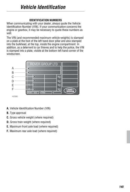
IDENTIFICATION NUMBERSWhen communicating with your dealer, always quote the VehicleIdentification Number (VIN). If your communication concerns theengine or gearbox, it may be necessary to quote these numbers aswell.
The VIN (and recommended maximum vehicle weights) is stampedon a plate at the foot of the left hand door pillar and also stampedinto the bulkhead, at the top, inside the engine compartment. Inaddition, as a deterrent to car thieves and to help the police, the VINis stamped into a plate, visible at the bottom left hand corner of thewindscreen.
A. Vehicle Identification Number (VIN)
B. Type approval
C. Gross vehicle weight (where required)
D. Gross train weight (where required)
E. Maximum front axle load (where required)
F. Maximum rear axle load (where required)
ABCDEF
H2390
Vehicle Identification
146
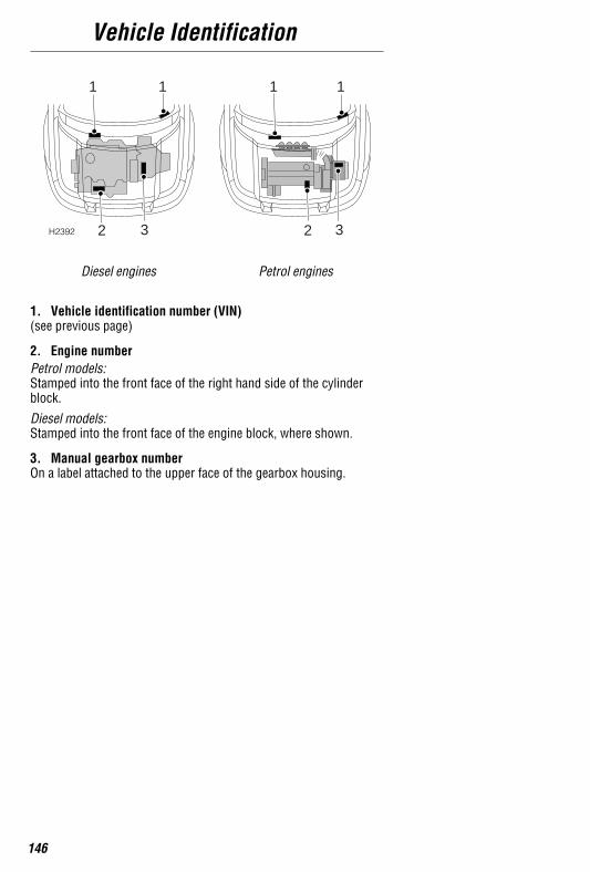
Diesel engines Petrol engines
1. Vehicle identification number (VIN)(see previous page)
2. Engine numberPetrol models:Stamped into the front face of the right hand side of the cylinderblock.
Diesel models:Stamped into the front face of the engine block, where shown.
3. Manual gearbox numberOn a label attached to the upper face of the gearbox housing.
H2392
1 1 1 1
2 23 3