freight car draft arrangements - wabtec …techinfo.wabtec.com/datafiles/leaflets/tp-2009.pdf · f....
TRANSCRIPT
TP2009
February 2003
FREIGHT CARDRAFT
ARRANGEMENTS
Student Workbook
Freight Car Draft Arrangements
1February 2003
Disclaimer
Thank you for making Wabtec Corporation your choice for educational material.
All our training publications are designed as teaching tools for a specific area of railway equipmentinstruction. As with any training literature, it will eventually become out of date. For this reason, itis important that only the current edition of this training package be used. To ensure you have thecurrent edition please contact your Wabtec representative. Wabtec Corporation produces a lineof instructional pamphlets and brochures for each of the components that Wabtec manufacturesto help augment the training process. This publication is under copyright to the WabtecCorporation. Any reproduction in whole or in part without written consent from an officer of WabtecCorporation is strictly prohibited.
This book may contain information covering some products manufactured by companies otherthan Wabtec. This is done to give you, the user, an opportunity to utilize one manual for themajority of your training requirements.
Information covering products not supplied by Wabtec Corporation is provided as a generalguide as to how these products should perform. Wabtec Corporation accepts no responsibilityfor the operation of products supplied by others, nor the information stated herein as to design orintended dimensional limits of such products.
Technical questions on the equipment shown in this booklet should be directed to the originalmanufacturer. If there are any discrepancies between this book and the original manufacturerstandards, the original manufacturer instructions take precedence.
Wabtec Corporation accepts no responsibility for injury or damage to personnel or equipmentresulting from either direct or indirect use of this manual.
For Technical Support contact your local Wabtec Corporation representative or Wabtec Trainingin Wilmerding, Pennsylvania, USA at 412-825-1453.
Michael ZenertMichael ZenertMichael ZenertMichael ZenertMichael Zenert(Michael Zenert)Manager - Air Brake TrainingWabtec Corporation
© 2003 Wabtec Corporation
Freight Car Draft Arrangements
2 February 2003
Contents
Part 1: Introduction ............................................................................................................ 3
Part 2: Draft Gear Components ......................................................................................... 3A. Coupler .................................................................................................................................................. 3
B. Follower Block or Plate ....................................................................................................................... 4
C. Draft Gear: ............................................................................................................................................. 4
D. Coupler Yoke ......................................................................................................................................... 5
E. Draft Gear Pocket ................................................................................................................................. 5
F. Draft Gear Carrier or Carrier Iron ........................................................................................................ 5
G. Draft Key or Cross Key ......................................................................................................................... 5
H. Draft Key (Cross Key) Retainer ............................................................................................................ 5
I. Draft Gear Lugs ...................................................................................................................................... 6
J. Striker Casting ....................................................................................................................................... 6
Part 3: Overview of the Draft Gear Connection and Components ................................. 7
Part 4: End of Car Cushioning and Cushion Underframes ............................................ 9A. End-of-Car Cushioning ......................................................................................................................... 9
B. Cushioned Underframe ........................................................................................................................ 9
Part 5: Internal Operation of a Draft Gear ....................................................................... 10Cardwell Westinghouse Draft Gears ..................................................................................................... 10
1. Mark 325 .............................................................................................................................................. 10
2. Mark 50 and Mark 500 ......................................................................................................................... 11
3. Mark H-60 ............................................................................................................................................ 12
Part 6: Articulated Connectors ........................................................................................ 13A. Cardwell Westinghouse SAC-1 Connector .............................................................................................. 13
B. ASF Articulated Connectors ..................................................................................................................... 17
C. National Articulated Connector ............................................................................................................... 18
Review Exercise ............................................................................................................... 19
Freight Car Draft Arrangements
3February 2003
Part 1: Introduction
The movement of railway equipment involves heavy pulling and pushing forces to move the weight ofthe cars as the train moves. This buffing and pulling action between each car and locomotive occurs eachtime the equipment moves. To ensure the car(s) and locomotive(s) can accept this movement withoutcausing damage to the equipment and/or lading, the equipment must have a system to absorb this punish-ment. The draft system is designed like a large shock absorber to accept the impact of car movementwithout resulting in equipment or lading damage. With the use of a draft system trains hauling many tons ofconsumer products and over a mile in length are possible. This workbook is designed for the draft arrange-ments associated with freight cars. Locomotive draft systems are similar but are not covered in this booklet.
Part 2: Draft Gear Components
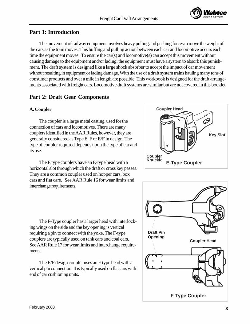
A. Coupler
The coupler is a large metal casting used for theconnection of cars and locomotives. There are manycouplers identified in the AAR Rules, however, they aregenerally considered as Type E, F or E/F in design. Thetype of coupler required depends upon the type of car andits use.
The E type couplers have an E-type head with ahorizontal slot through which the draft or cross key passes.They are a common coupler used on hopper cars, boxcars and flat cars. See AAR Rule 16 for wear limits andinterchange requirements.
The F-Type coupler has a larger head with interlock-ing wings on the side and the key opening is verticalrequiring a pin to connect with the yoke. The F-typecouplers are typically used on tank cars and coal cars.See AAR Rule 17 for wear limits and interchange require-ments.
The E/F design coupler uses an E type head with avertical pin connection. It is typically used on flat cars withend of car cushioning units.
Key Slot
Coupler Head
CouplerKnuckle E-Type Coupler
Coupler Head
Draft PinOpening
F-Type Coupler
Freight Car Draft Arrangements
4 February 2003
B. Follower Block or PlateThe rectangular metal plate placed inside the coupler yoke at the front of the draft gear. It acts as a stop
for the front of the draft gear in the pulling function. It transmits the stress of the draft gear force to the car centersill.
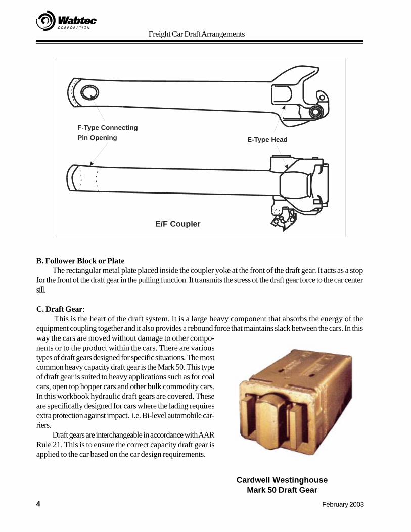
C. Draft Gear: This is the heart of the draft system. It is a large heavy component that absorbs the energy of the
equipment coupling together and it also provides a rebound force that maintains slack between the cars. In thisway the cars are moved without damage to other compo-nents or to the product within the cars. There are varioustypes of draft gears designed for specific situations. The mostcommon heavy capacity draft gear is the Mark 50. This typeof draft gear is suited to heavy applications such as for coalcars, open top hopper cars and other bulk commodity cars.In this workbook hydraulic draft gears are covered. Theseare specifically designed for cars where the lading requiresextra protection against impact. i.e. Bi-level automobile car-riers.
Draft gears are interchangeable in accordance with AARRule 21. This is to ensure the correct capacity draft gear isapplied to the car based on the car design requirements.
Cardwell WestinghouseMark 50 Draft Gear
F-Type ConnectingPin Opening E-Type Head
E/F Coupler
Freight Car Draft Arrangements
5February 2003
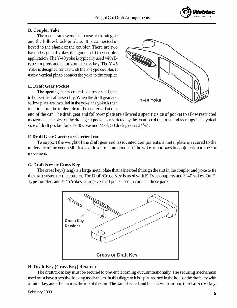
D. Coupler YokeThe metal framework that houses the draft gear
and the follow block or plate. It is connected orkeyed to the shank of the coupler. There are twobasic designs of yokes designed to fit the couplerapplication. The Y-40 yoke is typically used with E-type couplers and a horizontal cross key. The Y-45Yoke is designed for use with the F-Type coupler. Ituses a vertical pin to connect the yoke to the coupler.
E. Draft Gear PocketThe opening in the center sill of the car designed
to house the draft assembly. When the draft gear andfollow plate are installed in the yoke, the yoke is theninserted into the underside of the center sill at oneend of the car. The draft gear and follower plate are allowed a specific size of pocket to allow restrictedmovement. The size of the draft gear pocket is restricted by the location of the front and rear lugs. The typicalsize of draft pocket for a Y-40 yoke and Mark 50 draft gear is 245/8”.
F. Draft Gear Carrier or Carrier IronTo support the weight of the draft gear and associated components, a metal plate is secured to the
underside of the center sill. It also allows free movement of the yoke as it moves in conjunction to the carmovement.
G. Draft Key or Cross KeyThe cross key (slang) is a large metal plate that is inserted through the slot in the coupler and yoke to tie
the draft system to the coupler. The Draft/Cross Key is used with E-Type couplers and Y-40 yokes. On F-Type couplers and Y-45 Yokes, a large vertical pin is used to connect these parts.
Y-40 Yoke
H. Draft Key (Cross Key) RetainerThe draft/cross key must be secured to prevent it coming out unintentionally. The securing mechanism
used must have a positive locking mechanism. In this diagram it is a pin inserted in the hole of the draft key witha cotter key and a bar across the top of the pin. The bar is heated and bent to wrap around the draft/cross key.
Cross KeyRetainer
Cross or Draft Key
Freight Car Draft Arrangements
6 February 2003
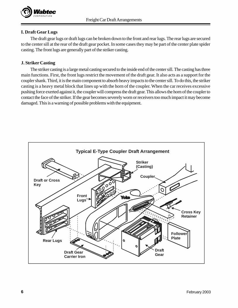
I. Draft Gear LugsThe draft gear lugs or draft lugs can be broken down to the front and rear lugs. The rear lugs are secured
to the center sill at the rear of the draft gear pocket. In some cases they may be part of the center plate spidercasting. The front lugs are generally part of the striker casting.
J. Striker CastingThe striker casting is a large metal casting secured to the inside end of the center sill. The casting has three
main functions. First, the front lugs restrict the movement of the draft gear. It also acts as a support for thecoupler shank. Third, it is the main component to absorb heavy impacts to the center sill. To do this, the strikercasting is a heavy metal block that lines up with the horn of the coupler. When the car receives excessivepushing force exerted against it, the coupler will compress the draft gear. This allows the horn of the coupler tocontact the face of the striker. If the gear becomes severely worn or receivers too much impact it may becomedamaged. This is a warning of possible problems with the equipment.
Draft or CrossKey
Striker(Casting)
Coupler
Cross KeyRetainer
FollowerPlate
DraftGearDraft Gear
Carrier Iron
Rear Lugs
FrontLugs
Typical E-Type Coupler Draft Arrangement

Freight Car Draft Arrangements
7February 2003
Part 3: Overview of the Draft Gear Connection and Components
On page 6 is an exploded view of the typical components of an E-Type Coupler draft arrangement asthey are designed to fit into the center sill of a freight car. The heart of the draft system is the draft gear. It isassembled in a fashion that it will cause it to be compressed in both directions, pushing and pulling. This willutilize the full operating effectiveness of the gear.
Pushing Position
In the draft or pushing position, the car or locomotive is moved by pushing on the coupler. Havingslack between the cars and in the draft system allows for movement of the equipment without having tomove the train as a solid block. In the diagram below you will see the pushing force on the front of thecoupler will cause the end of the coupler shank to make contact with the follower plate. The follower platemakes contact with the front of the draft gear. At the opposite end of the draft gear are draft stops or lugsattached to the center sill. They form the rear end of the draft pocket. With the follower plate forcing thefront of the draft gear back, the rear of the draft gear cannot move any farther back because of the lugs. Theresult is the internal components of the draft gear are compressed to act as a shock absorber to the pushingmovement. This is a typical E-Type Coupler arrangement. For other types of coupler and draft systems, thebasic function remains the same. The only difference is the type and capacity of the draft gear.
Draft Gear in Pushing Position
Coupler
Yoke Follower
Draft Gear
Rear Lugs
Freight Car Draft Arrangements
8 February 2003
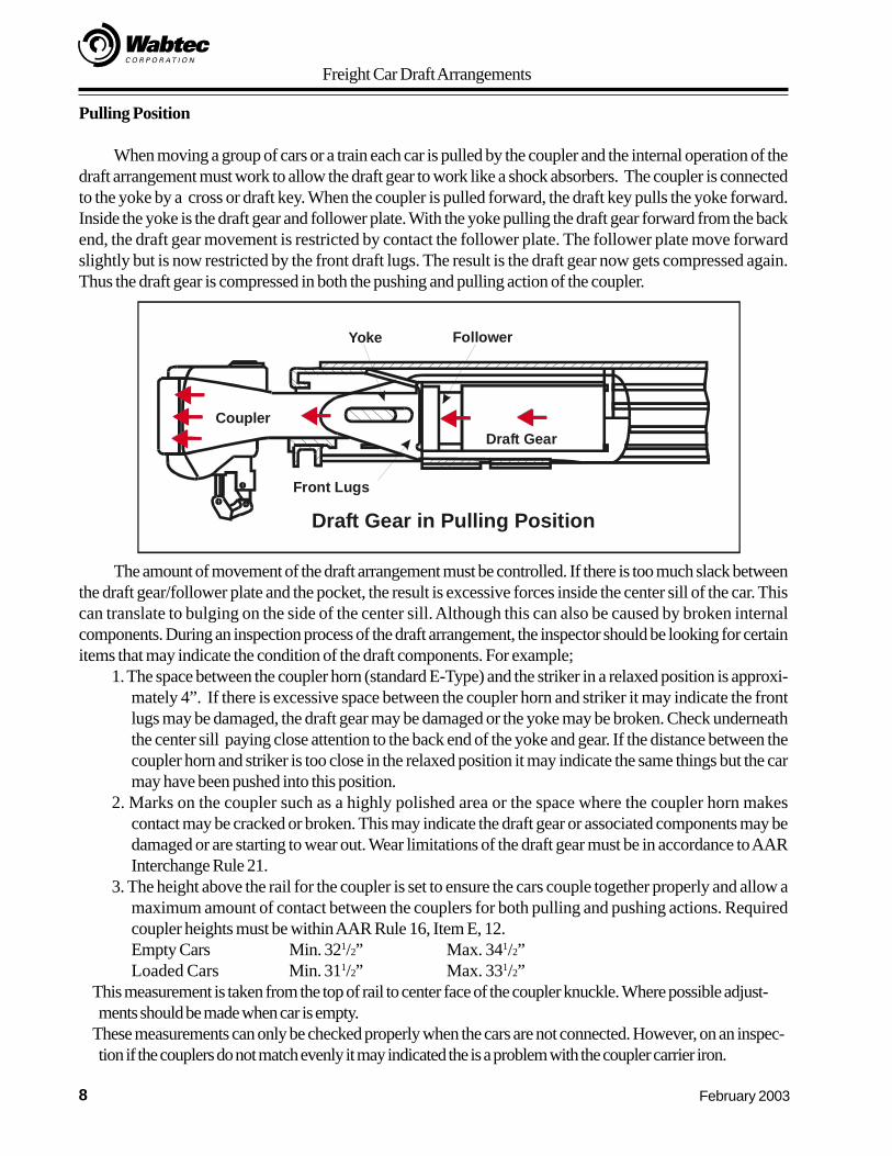
Pulling Position
When moving a group of cars or a train each car is pulled by the coupler and the internal operation of thedraft arrangement must work to allow the draft gear to work like a shock absorbers. The coupler is connectedto the yoke by a cross or draft key. When the coupler is pulled forward, the draft key pulls the yoke forward.Inside the yoke is the draft gear and follower plate. With the yoke pulling the draft gear forward from the backend, the draft gear movement is restricted by contact the follower plate. The follower plate move forwardslightly but is now restricted by the front draft lugs. The result is the draft gear now gets compressed again.Thus the draft gear is compressed in both the pushing and pulling action of the coupler.
The amount of movement of the draft arrangement must be controlled. If there is too much slack betweenthe draft gear/follower plate and the pocket, the result is excessive forces inside the center sill of the car. Thiscan translate to bulging on the side of the center sill. Although this can also be caused by broken internalcomponents. During an inspection process of the draft arrangement, the inspector should be looking for certainitems that may indicate the condition of the draft components. For example;
1. The space between the coupler horn (standard E-Type) and the striker in a relaxed position is approxi-mately 4”. If there is excessive space between the coupler horn and striker it may indicate the frontlugs may be damaged, the draft gear may be damaged or the yoke may be broken. Check underneaththe center sill paying close attention to the back end of the yoke and gear. If the distance between thecoupler horn and striker is too close in the relaxed position it may indicate the same things but the carmay have been pushed into this position.
2. Marks on the coupler such as a highly polished area or the space where the coupler horn makescontact may be cracked or broken. This may indicate the draft gear or associated components may bedamaged or are starting to wear out. Wear limitations of the draft gear must be in accordance to AARInterchange Rule 21.
3. The height above the rail for the coupler is set to ensure the cars couple together properly and allow amaximum amount of contact between the couplers for both pulling and pushing actions. Requiredcoupler heights must be within AAR Rule 16, Item E, 12.Empty Cars Min. 321/2” Max. 341/2”Loaded Cars Min. 311/2” Max. 331/2”
This measurement is taken from the top of rail to center face of the coupler knuckle. Where possible adjust-ments should be made when car is empty.
These measurements can only be checked properly when the cars are not connected. However, on an inspec-tion if the couplers do not match evenly it may indicated the is a problem with the coupler carrier iron.
Draft Gear in Pulling PositionFront Lugs
Coupler
Yoke Follower
Draft Gear
Freight Car Draft Arrangements
9February 2003
Part 4: End of Car Cushioning and Cushion Underframes
A. End-of-Car CushioningEnd of car cushioning units are similar in operation to standard draft arrangements. In both cases the draft
arrangement must work like shock absorbers for the car. End-of-car equipment is generally used with carscarrying products that are susceptible to damage if the car was subjected to heavy shunting action. Items suchas automobiles, boats, electronic equipment require a softer draft arrangement than cars carrying coal, potashor other bulk commodities. To provide a softer contact for goods that are susceptible to damage the car usuallyhas a long shank coupler and a hydraulic or pneumatic type of draft gear. This type of draft arrangement allowsfor longer travel of the coupler and draft system to provide a softer, smoother buffing and pulling on the car.
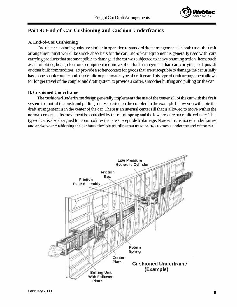
B. Cushioned UnderframeThe cushioned underframe design generally implements the use of the center sill of the car with the draft
system to control the push and pulling forces exerted on the coupler. In the example below you will note thedraft arrangement is in the center of the car. There is an internal center sill that is allowed to move within thenormal center sill. Its movement is controlled by the return spring and the low pressure hydraulic cylinder. Thistype of car is also designed for commodities that are susceptible to damage. Note with cushioned underframesand end-of-car cushioning the car has a flexible trainline that must be free to move under the end of the car.
Low PressureHydraulic Cylinder
Return Spring
Buffing Unit With Follower Plates
Friction Box
Friction Plate Assembly
Center Plate Cushioned Underframe
(Example)
Freight Car Draft Arrangements
10 February 2003
Part 5: Internal Operation of a Draft GearThe design of a draft gear is important for the proper buffeting and pulling operation on the car. The draft
gear not only returns the coupler after each connection but more importantly it provides cushioning to preventdamage to the car and lading. Matching the draft gear to the type of car and its specific use is important toprovide the correct cushioning effect on the car.
Draft gears typically use a system of springs and wedges to absorb and nullify the force exerted on them.The initial impact from the follower plate is directed through a series of wedges to the springs inside the gearhousing. The wedges are geometrically arranged to absorb the coupler force and slow down the reaction tothis force in much the same fashion a shock absorber is used in an automobile. The springs provide an initialresistance to the heavy follower plate contact from the coupler and also lengthen the friction pack to fill out thepocket.
Cardwell Westinghouse Draft Gears
1. Mark 325
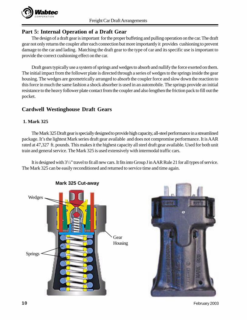
The Mark 325 Draft gear is specially designed to provide high capacity, all-steel performance in a streamlinedpackage. It’s the lightest Mark series draft gear available and does not compromise performance. It is AARrated at 47,327 ft. pounds. This makes it the highest capacity all steel draft gear available. Used for both unittrain and general service. The Mark 325 is used extensively with intermodal traffic cars.
It is designed with 31/4” travel to fit all new cars. It fits into Group J in AAR Rule 21 for all types of service.The Mark 325 can be easily reconditioned and returned to service time and time again.
Wedges
GearHousing
Springs
Mark 325 Cut-away
Freight Car Draft Arrangements
11February 2003
2. Mark 50 and Mark 500
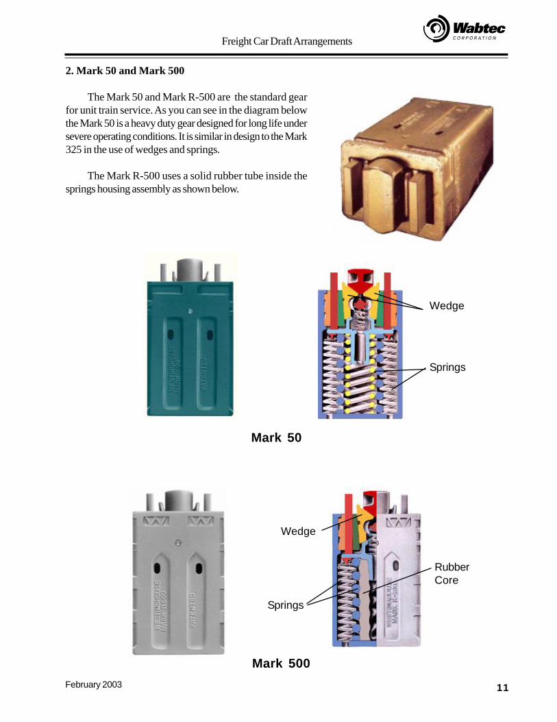
The Mark 50 and Mark R-500 are the standard gearfor unit train service. As you can see in the diagram belowthe Mark 50 is a heavy duty gear designed for long life undersevere operating conditions. It is similar in design to the Mark325 in the use of wedges and springs.
The Mark R-500 uses a solid rubber tube inside thesprings housing assembly as shown below.
Mark 50
Mark 500
Wedge
Springs
Wedge
Springs
RubberCore
Freight Car Draft Arrangements
12 February 2003
3. Mark H-60
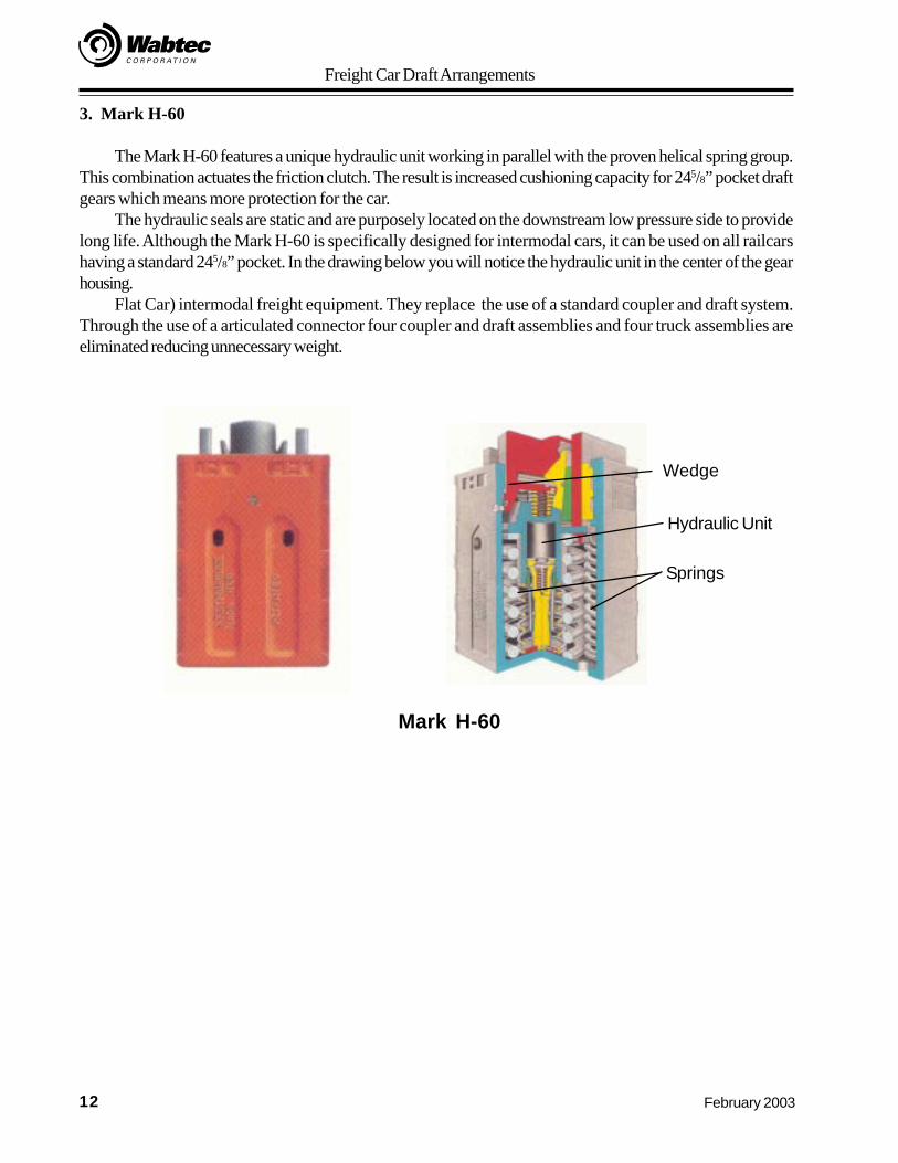
The Mark H-60 features a unique hydraulic unit working in parallel with the proven helical spring group.This combination actuates the friction clutch. The result is increased cushioning capacity for 245/8” pocket draftgears which means more protection for the car.
The hydraulic seals are static and are purposely located on the downstream low pressure side to providelong life. Although the Mark H-60 is specifically designed for intermodal cars, it can be used on all railcarshaving a standard 245/8” pocket. In the drawing below you will notice the hydraulic unit in the center of the gearhousing.
Flat Car) intermodal freight equipment. They replace the use of a standard coupler and draft system.Through the use of a articulated connector four coupler and draft assemblies and four truck assemblies areeliminated reducing unnecessary weight.
Springs
Hydraulic Unit
Wedge
Mark H-60
Freight Car Draft Arrangements
13February 2003
Part 6: Articulated Connectors
Cars equipped with articulated connectors are typically multiple unit TOFC/COFC ( Trailer on Flat Car/Container or Container on Flat Car) cars. They have a conventional type draft assembly on the end of the multiunit car, but in between the well or flat units they are connected with a special type of assembly called anarticulated connector. The articulated connectors save weight, parts and equipment. On standard freight cars,each car has its own draft assembly at each end. They also have a complete truck assembly at each endincluding truck bolsters, side frames and wheels. On multi unit cars set up with articulated connectors, there isone truck assembly between each two flat units or well units. This cuts down on the number of truck assembliesrequired. To make a connection between the cars the articulated connector is mounted fit into the center plateof the truck bolster. There are three types of articulated connectors.
A. Cardwell Westinghouse SAC-1 Connector
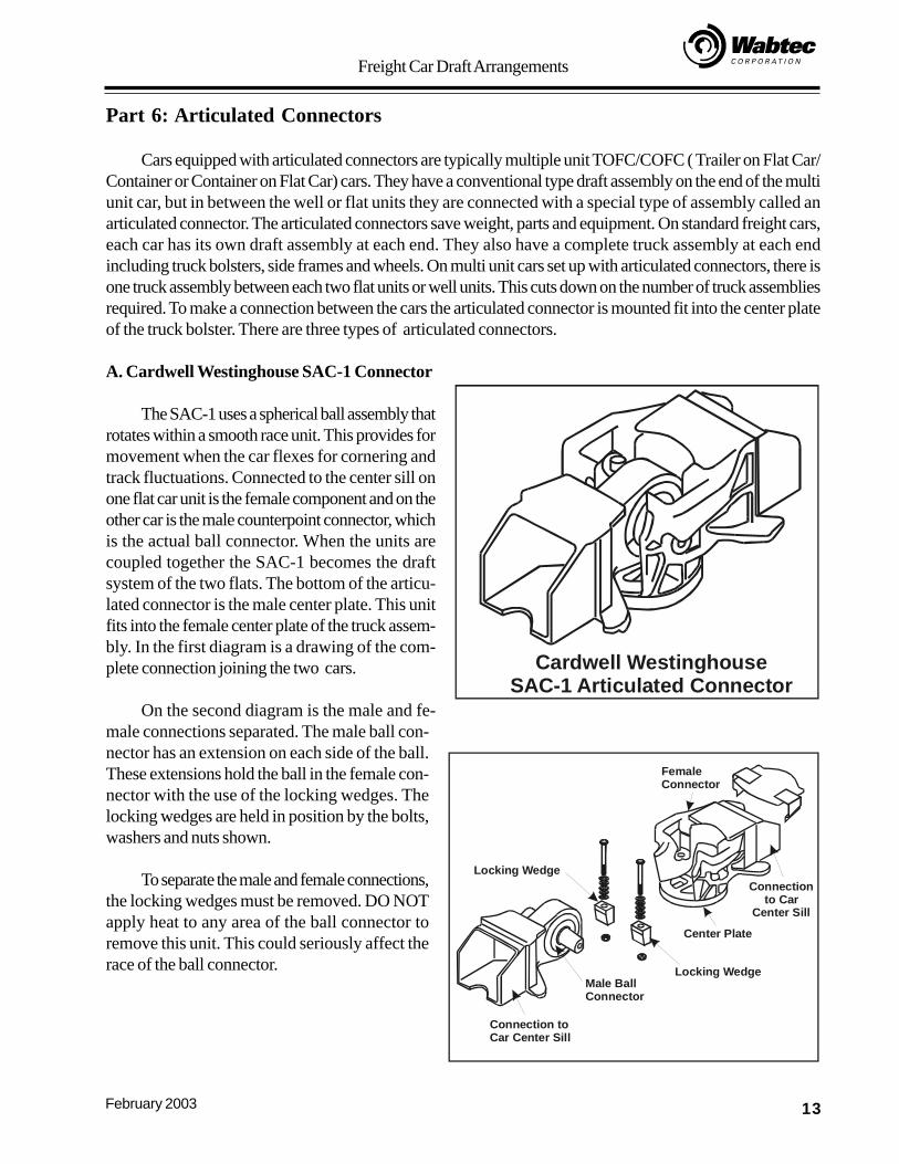
The SAC-1 uses a spherical ball assembly thatrotates within a smooth race unit. This provides formovement when the car flexes for cornering andtrack fluctuations. Connected to the center sill onone flat car unit is the female component and on theother car is the male counterpoint connector, whichis the actual ball connector. When the units arecoupled together the SAC-1 becomes the draftsystem of the two flats. The bottom of the articu-lated connector is the male center plate. This unitfits into the female center plate of the truck assem-bly. In the first diagram is a drawing of the com-plete connection joining the two cars.
On the second diagram is the male and fe-male connections separated. The male ball con-nector has an extension on each side of the ball.These extensions hold the ball in the female con-nector with the use of the locking wedges. Thelocking wedges are held in position by the bolts,washers and nuts shown.
To separate the male and female connections,the locking wedges must be removed. DO NOTapply heat to any area of the ball connector toremove this unit. This could seriously affect therace of the ball connector.
Cardwell WestinghouseSAC-1 Articulated Connector
FemaleConnector
Center Plate
Connectionto Car
Center Sill
Male BallConnector
Locking Wedge
Connection toCar Center Sill
Locking Wedge
Freight Car Draft Arrangements
14 February 2003
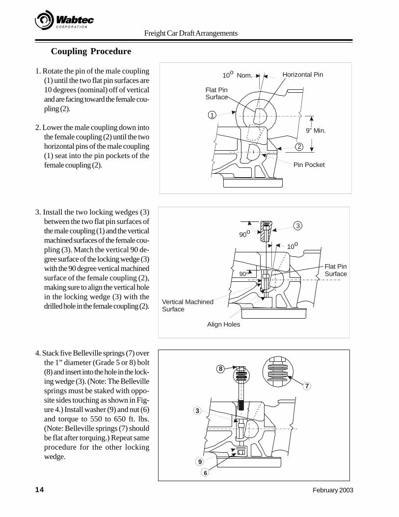
Coupling Procedure
1. Rotate the pin of the male coupling(1) until the two flat pin surfaces are10 degrees (nominal) off of verticaland are facing toward the female cou-pling (2).
2. Lower the male coupling down intothe female coupling (2) until the twohorizontal pins of the male coupling(1) seat into the pin pockets of thefemale coupling (2).
3. Install the two locking wedges (3)between the two flat pin surfaces ofthe male coupling (1) and the verticalmachined surfaces of the female cou-pling (3). Match the vertical 90 de-gree surface of the locking wedge (3)with the 90 degree vertical machinedsurface of the female coupling (2),making sure to align the vertical holein the locking wedge (3) with thedrilled hole in the female coupling (2).
4. Stack five Belleville springs (7) overthe 1” diameter (Grade 5 or 8) bolt(8) and insert into the hole in the lock-ing wedge (3). (Note: The Bellevillesprings must be staked with oppo-site sides touching as shown in Fig-ure 4.) Install washer (9) and nut (6)and torque to 550 to 650 ft. lbs.(Note: Belleville springs (7) shouldbe flat after torquing.) Repeat sameprocedure for the other lockingwedge.
Flat PinSurface
10o Nom. Horizontal Pin
Pin Pocket
1
2
9” Min.
Vertical MachinedSurface
Flat Pin Surface
90o
Align Holes
3
90o
7
8
3
96
10o
Freight Car Draft Arrangements
15February 2003
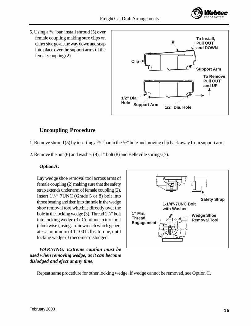
5. Using a 3/8” bar, install shroud (5) overfemale coupling making sure clips oneither side go all the way down and snapinto place over the support arms of thefemale coupling (2).
Uncoupling Procedure
1. Remove shroud (5) by inserting a 3/8” bar in the 1/2” hole and moving clip back away from support arm.
2. Remove the nut (6) and washer (9), 1” bolt (8) and Belleville springs (7).
Option A:
Lay wedge shoe removal tool across arms offemale coupling (2) making sure that the safetystrap extends under arm of female coupling (2).Insert 11/4” 7UNC (Grade 5 or 8) bolt intothrust bearing and then into the hole in the wedgeshoe removal tool which is directly over thehole in the locking wedge (3). Thread 11/4” boltinto locking wedge (3). Continue to turn bolt(clockwise), using an air wrench which gener-ates a minimum of 1,100 ft. lbs. torque, untillocking wedge (3) becomes dislodged.
WARNING: Extreme caution must beused when removing wedge, as it can becomedislodged and eject at any time.
Repeat same procedure for other locking wedge. If wedge cannot be removed, see Option C.
To Install,Pull OUT and DOWN
To Remove:Pull OUTand UP
5
Clip
Support Arm
1/2” Dia. HoleSupport Arm1/2” Dia.Hole
Safety Strap
Wedge ShoeRemoval Tool
1-1/4”-7UNC Boltwith Washer
1” Min.ThreadEngagement
Freight Car Draft Arrangements
16 February 2003
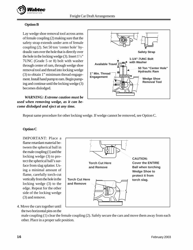
Option B
Lay wedge shoe removal tool across armsof female coupling (2) making sure that thesafety strap extends under arm of femalecoupling (2). Set 50 ton ‘center hole’ hy-draulic ram over the hole that is directly overthe hole in the locking wedge (3). Insert 11/4”7UNC (Grade 5 or 8) bolt with washerthrough center of ram, through wedge shoeremoval tool and thread into locking wedge(3) to obtain 1” minimum thread engage-ment. Install hand pump to ram. Begin pump-ing and continue until the locking wedge (3)becomes dislodged.
WARNING: Extreme caution must beused when removing wedge, as it can be-come dislodged and eject at any time.
Repeat same procedure for other locking wedge. If wedge cannot be removed, see Option C.
Option C
IMPORTANT: Place aflame retardant material be-tween the spherical ball inthe male coupling (1) and thelocking wedge (3) to pro-tect the spherical ball’s sur-face from slag splatter. Us-ing a minimal amount offlame, carefully torch-cutvertically from the hole in thelocking wedge (3) to theedge. Repeat for the otherside of the locking wedge(3) and remove.
4. Move the cars together untilthe two horizontal pins on themale coupling (1) clear the female coupling (2). Safely secure the cars and move them away from eachother. Place in a proper safe position.
Safety Strap
Available Travel 3”50 Ton “Center Hole”Hydraulic Ram1” Min. Thread
Engagement Wedge ShoeRemoval Tool
1-1/4”-7UNC Boltwith Washer
Torch Cut Hereand Remove
CAUTION:Cover the ENTIREBall when torchingWedge Shoe to protect it fromtorch slag.Torch Cut Here
and Remove
Freight Car Draft Arrangements
17February 2003
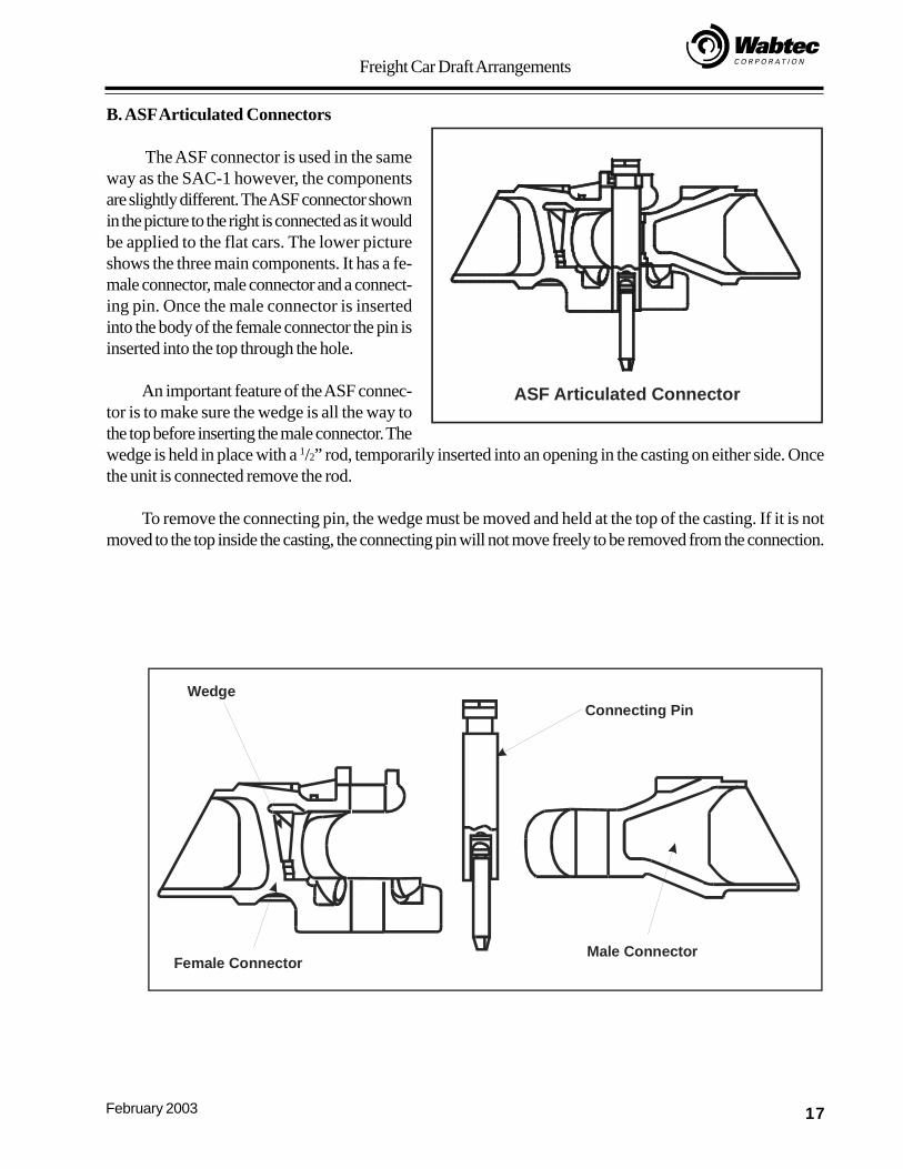
B. ASF Articulated Connectors
The ASF connector is used in the sameway as the SAC-1 however, the componentsare slightly different. The ASF connector shownin the picture to the right is connected as it wouldbe applied to the flat cars. The lower pictureshows the three main components. It has a fe-male connector, male connector and a connect-ing pin. Once the male connector is insertedinto the body of the female connector the pin isinserted into the top through the hole.
An important feature of the ASF connec-tor is to make sure the wedge is all the way tothe top before inserting the male connector. Thewedge is held in place with a 1/2” rod, temporarily inserted into an opening in the casting on either side. Oncethe unit is connected remove the rod.
To remove the connecting pin, the wedge must be moved and held at the top of the casting. If it is notmoved to the top inside the casting, the connecting pin will not move freely to be removed from the connection.
ASF Articulated Connector
WedgeConnecting Pin
Male ConnectorFemale Connector
Freight Car Draft Arrangements
18 February 2003
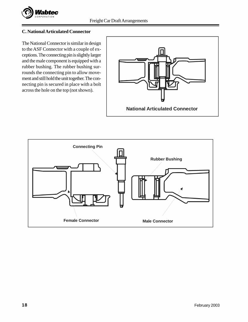
C. National Articulated Connector
The National Connector is similar in designto the ASF Connector with a couple of ex-ceptions. The connecting pin is slightly largerand the male component is equipped with arubber bushing. The rubber bushing sur-rounds the connecting pin to allow move-ment and still hold the unit together. The con-necting pin is secured in place with a boltacross the hole on the top (not shown).
National Articulated Connector
Connecting Pin
Rubber Bushing
Male ConnectorFemale Connector
Freight Car Draft Arrangements
19February 2003
Review Exercise
1. The draft gear and follower block are placed inside the pocket of the_________________.
2. The draft gear is compressed in the:
a. Pulling function
b. Pushing function
c. a and b
d. None of the above
3. To connect an E-Type coupler to the yoke a ___________________ isused to ensure the draft gear operates properly.
4. Standard coupler heights above the top of the rail per AAR Rule 16 are:Empty Car Min. ______ Max. ______Loaded Car Min. ______ Max. ______
5. On a SAC-1 articulated connector, what are the wedges used for?______________________________________________________
6. On an ASF articulated connector, what must be done to ensure theconnection pin can be inserted or removed properly?
______________________________________________________
Freight Car Draft Arrangements
20 February 2003
Review Exercise - Answers
1. The draft gear and follower block are placed inside the pocket of the Yoke
2. The draft gear is compressed in the:
a. Pulling function
b. Pushing function
c. a and b
d. None of the above
4. Standard coupler heights above the top of the rail per AAR Rule 16 are:Empty Car Min. 32 1/2” Max. 34 1/2”Loaded Car Min. 31 1/2” Max. 33 1/2”
5. On a SAC-1 articulated connector, what are the wedges used for?Secure the ball connector in place
6. On an ASF articulated connector, what must be done to ensure theconnection pin can be inserted or removed properly?
The wedge must be all the way to the top