frenomat und frenostat electronic brake units - … · electronic brake units ... commissioning:...
TRANSCRIPT
Hilger u. Kern Industrieelektronik
frenomat® und frenostat®
Electronic Brake UnitsThe quick and reliable way to bring things to a standstill
– with no mechanical wear

2

3
Page
General information . . . . . . . . . . . . . . . . . . . . . . . . . . . . . . . . . . . . . . . . . . . . . . . . . . . 4• EU Declaration of Conformity . . . . . . . . . . . . . . . . . . . . . . . . . . . . . . . . . . . . . . . 4• Line choke . . . . . . . . . . . . . . . . . . . . . . . . . . . . . . . . . . . . . . . . . . . . . . . . . . . . . . 4• Certification of mechanical stability . . . . . . . . . . . . . . . . . . . . . . . . . . . . . . . . . . . 4
Application / Operating principle . . . . . . . . . . . . . . . . . . . . . . . . . . . . . . . . . . . . . . . . . 5
frenomat 2 brake unit . . . . . . . . . . . . . . . . . . . . . . . . . . . . . . . . . . . . . . . . . . . . . . . . . . 6
frenostat 2000 brake unit . . . . . . . . . . . . . . . . . . . . . . . . . . . . . . . . . . . . . . . . . . . . . . . 7
Technical data: frenomat 2/frenostat 2000 brake units . . . . . . . . . . . . . . . . . . . . . . . . 9
Dimensions: frenostat 2000 . . . . . . . . . . . . . . . . . . . . . . . . . . . . . . . . . . . . . . . . . . . . 10
Examples of circuits: frenostat 2000 . . . . . . . . . . . . . . . . . . . . . . . . . . . . . . . . . . 11-14
Accessory: line choke . . . . . . . . . . . . . . . . . . . . . . . . . . . . . . . . . . . . . . . . . . . . . . . . . 14
Commissioning: frenomat 2/frenostat 2000 . . . . . . . . . . . . . . . . . . . . . . . . . . . . . . . 15
International sales organization . . . . . . . . . . . . . . . . . . . . . . . . . . . . . . . . . . . . . . . . . 15
Contents

4
Hilger u. Kern Industrieelektronik here withdeclares with respect to the products itmanufactures and named below
frenomat electronic brake unit,frenostat electronic brake unit,
that the requirements relating to electro-magnetic compatibility (EMC) as laid downin EU Directive 2014/30/EU are met.
Assessment of the product has been basedon the following standards:
• IEC 947-4-2 AC semiconductor motorcontrollers and starters
• EN 55011 Generic Emission Standard03.93
• EN 61000-4-3 Generic Immunity Standard 08.94
The corresponding measurements havebeen confirmed and documented by theGerman technical inspectorate TÜV-Süd-west in Mannheim.
The units named above are labeled with aCE mark of conformity.
The emission limits laid down in the Euro-pean standards do not exclude interfer-ence of receivers within a radius of 10 m.
During operation, i.e. braking, frenostatand frenomat electronic brake units remainwithin the limits of European standard EN 61000-6-4 (mains-borne interference)with regard to the power cables if a line
choke is installed directly on the line ter-minal. This accessory is available fromHilger u. Kern Industrieelektronik (seepage 14).The enclosures of the frenostat brakeunits are made of environmentally friendly,recyclable materials.
frenostat electronic brake unit No.12524100 has been subjected to a typetest in accordance with DIN 57 Part2/VDE 0160 Part 2, Section 4.2.
This test is valid for all frenostat brakeunits that have been manufactured sinceJanuary 1, 1978.The results of the measurements taken
have revealed that the brake unit morethan complies with the requirements laiddown in VDE 0160 Part 2, Section 4.2.
Operational reliability of the frenostat brakeunit was unaffected.
General information
EU Declaration of Conformity
Line choke
Certification of mechanical stability

frenomat and frenostat electronic brakeunits
• reliably and quickly brake asynchro-nous motors to a standstill withoutrequiring any maintenance or sufferingany wear.
• are the perfect solution for shorteninglong coasting times (saving time andcosts).
• are components that can be retrofittedin control cabinets without any problem.
• are maintenance- and wear-free.
Due to systematic action taken to meetthe demands of the market, frenomat andfrenostat electronic brake units have a
wider power spectrum than units compa-rable in design. In particular, the followingfeatures designed to increase service reli-ability must be highlighted:
• visual indication of the operating state
• proven snubber circuit to protectagainst voltage peaks
• generous rating of the heat sinks
• high degree of service reliability – evenunder rough service and ambientconditions – thanks to protective lacquering
• captive connecting screws
• automatic standstill monitoring.
Application / Operating principle
Basic circuitryof the main circuit
(basic layout)
Braking torque curve withasynchronous motors asa factor of the speed
Operating principle
Application example:vibrating screen
A rugged power converter, working inconjunction with floating, digital controlelectronics, generates a powerful brakingtorque.
The braking effect is initiated by anadjustable direct current that flows through
the motor winding. A stationary magneticfield, which acts as a static field, retardsthe rotational movement of the rotor. Thebraking torque that results from this followsthe curve depicted against the speed.
A frenostat 2000 electronic brake unitbrings the 30-kW drive to a standstill withinjust a few seconds. This prevents danger-ous sympathetic (resonant) oscillations.Use of the frenostat 2000 made it possibleto do without elaborate and costly concretefoundations.
▲▲▲
5

6
frenomat 2electronic brake unit
Circuit diagram
Dimensions
The frenomat 2 electronic brake unitquickly and reliably brakes three-phaseAC motors with a power output of up to 3kW. frenomat 2 brake units are compactand suitable for snap-fitting on DIN rails.They are only 55 mm wide!The control and power circuits are housedin a rigid and unbreakable plastic enclosure.The braking current and braking time areboth infinitely variable and can be adjustedmanually.frenomat 2 is also equipped with a standstillmonitoring unit on terminal n1 to allow itto be used with drives whose rotatingmass is frequently changed.
▲▲
7
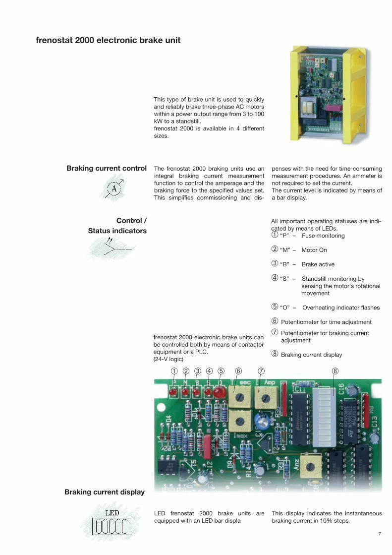
This type of brake unit is used to quicklyand reliably brake three-phase AC motorswithin a power output range from 3 to 100kW to a standstill.frenostat 2000 is available in 4 differentsizes.
frenostat 2000 electronic brake units canbe controlled both by means of contactorequipment or a PLC.(24-V logic)
All important operating statuses are indi-cated by means of LEDs.➀ “P” – Fuse monitoring
➁ “M” – Motor On
➂ “B” – Brake active
➃ “S” – Standstill monitoring by sensing the motor's rotationalmovement
➄ “O” – Overheating indicator flashes
➅ Potentiometer for time adjustment
➆ Potentiometer for braking currentadjustment
➇ Braking current display
The frenostat 2000 braking units use anintegral braking current measurementfunction to control the amperage and thebraking force to the specified values set.This simplifies commissioning and dis-
penses with the need for time-consumingmeasurement procedures. An ammeter isnot required to set the current.The current level is indicated by means ofa bar display.
➀ ➁ ➂ ➃ ➄ ➅ ➆ ➇
frenostat 2000 electronic brake unit
LED frenostat 2000 brake units areequipped with an LED bar displa
This display indicates the instantaneousbraking current in 10% steps.
Braking current control
Control / Status indicators
Braking current display

8
Size of connection cables
Braking current rating The motor current (IM) must be knownbefore the necessary braking current (IB)can be rated:
The braking current should be more than3 times higher than the rated motor current.When placing an order, only the brakingcurrent amperage and the line voltageshould be specified.The maximum braking current of the vari-ous sizes of brake unit can be found inthe table on page 9.
IB = necessary braking current in amperes
IM = rated motor current in amperes
Order text:
frenostat 2000 Size 2Braking current 100 ALine voltage 400 V
lB = 3 x lM^
^
The cross-section of the cables connectedto terminals 8, a and b is identical to thatof the motor connection cables.
The cable connected to terminal n1 is aninstrument lead (<1 A); a cross-section of0.75 mm2 is sufficient.
Overheating protection
Standstill monitoring
Interlocking contact
Choice of brake unit fuses
Choice of braking contactor
In order to increase operational reliability,frenostat 2000 brake units are equippedwith an integral temperature-measuringfunction.
In the event of the unit overheating, dueto too frequent braking for example, brak-ing is executed until the motor comes to astandstill, but the motor is prevented from
restarting. A floating relay contact (n3, n4)remains closed. In addition, LED “O”flashes to indicate overheating.Once the brake unit has cooled down toits normal operating temperature, therelay contact (n3, n4) is opened again.LED “O” stops flashing.
An integrated standstill monitoring unitalters the operating time of the brakedepending on the variable rotating massof the overall drive. A manual time settingis not needed.
Activation of this monitoring unit is indi-cated by LED “S”.
The control unit is connected to terminaln1 by means of an instrument lead (0.75mm2). Measurement is triggered by thebraking contactor by means of an auxiliarycontact. If motor leads with a cross-section>1.5 mm2 are used, a 2-A fuse must befitted to protect the instrument lead.
frenostat brake units are equipped with afloating changeover contact. NC contactn4 – n2 opens after the motor has startedand in this way allows the motor to bestarted again only after braking has beencompleted.
The interlocking contact can perform thefollowing functions:• protect against overheating• interlock immediate reclosure following
the OFF command without braking (see
examples of circuits)• indicate readiness: the motor is only
released by a PLC for reclosure oncethe contact is in its normal position
• interlock a hood or cover: a protectivehood or cover can only be openedwhen the drive is at rest
• report standstill• open a mechanical holding brake.
The 2 brake unit fuses serve among otherthings to protect the motor against over-loading. These fuses must be adapted tomatch the rated current of the motor.
Rated fuse current = approx. 150% of ratedmotor current. See basic circuit on page13 for circuitry of fuse F4.
Size of braking contactor = size of motorcontactor. The contactor is energized and
de-energized without current being appliedto the main contacts.
9
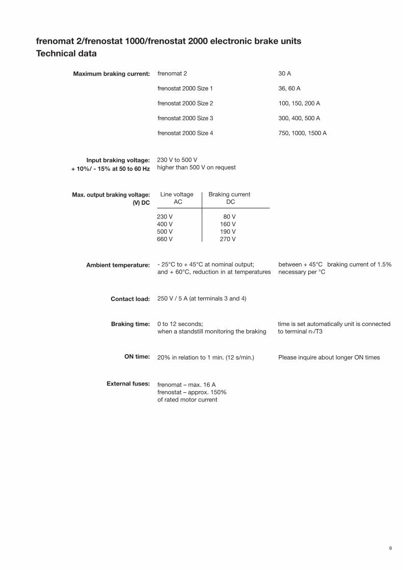
Line voltage Braking currentAC DC
230 V 80 V400 V 160 V500 V 190 V660 V 270 V
Maximum braking current:
Input braking voltage:+ 10%/ - 15% at 50 to 60 Hz
Max. output braking voltage:(V) DC
Ambient temperature:
Contact load:
Braking time:
ON time:
External fuses:
Please inquire about longer ON times
230 V to 500 Vhigher than 500 V on request
- 25°C to + 45°C at nominal output;and + 60°C, reduction in at temperatures
between + 45°C braking current of 1.5%necessary per °C
0 to 12 seconds;when a standstill monitoring the braking
time is set automatically unit is connectedto terminal n1/T3
250 V / 5 A (at terminals 3 and 4)
20% in relation to 1 min. (12 s/min.)
frenomat – max. 16 Afrenostat – approx. 150% of rated motor current
30 A
36, 60 A
100, 150, 200 A
300, 400, 500 A
750, 1000, 1500 A
frenomat 2
frenostat 2000 Size 1
frenostat 2000 Size 2
frenostat 2000 Size 3
frenostat 2000 Size 4
frenomat 2/frenostat 1000/frenostat 2000 electronic brake unitsTechnical data
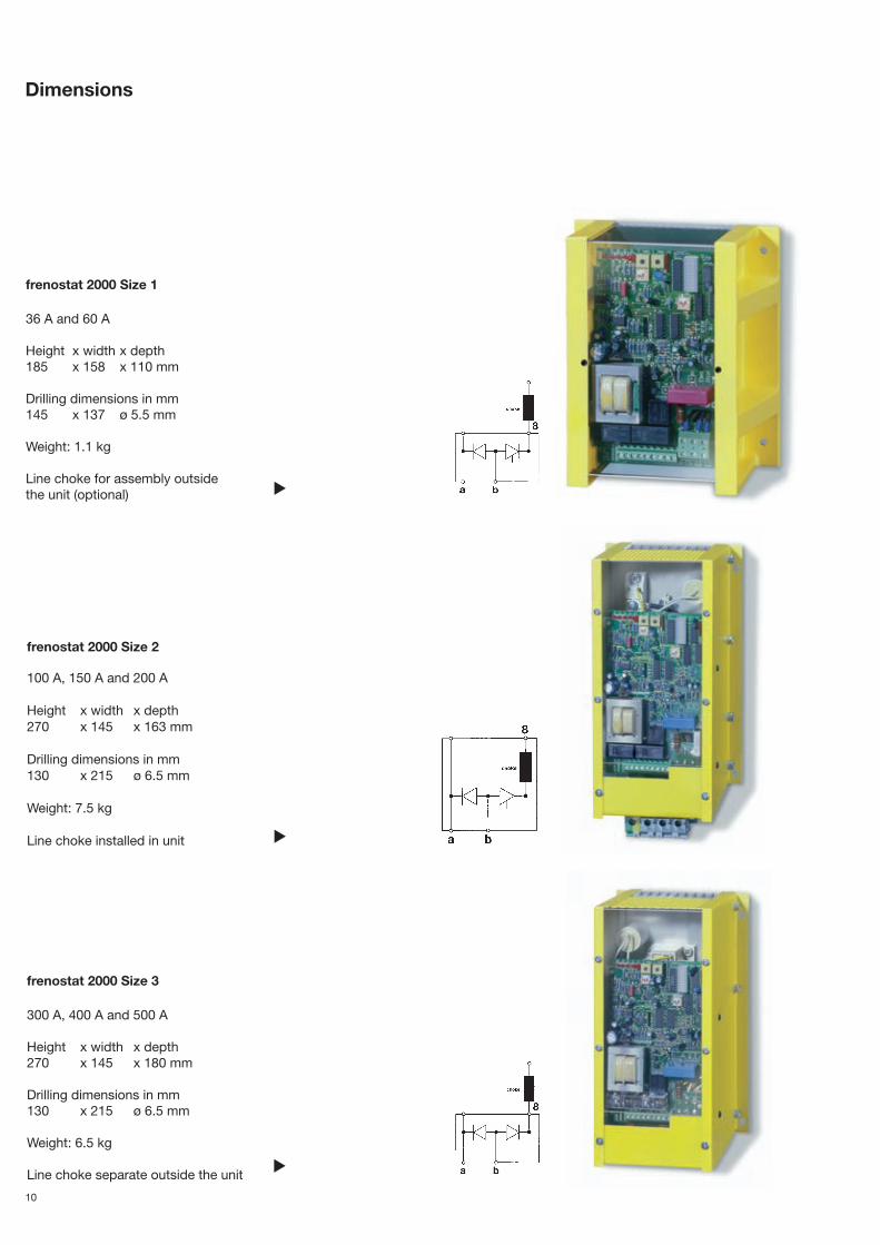
10
frenostat 2000 Size 2
100 A, 150 A and 200 A
Height x width x depth270 x 145 x 163 mm
Drilling dimensions in mm130 x 215 ø 6.5 mm
Weight: 7.5 kg
Line choke installed in unit
frenostat 2000 Size 3
300 A, 400 A and 500 A
Height x width x depth270 x 145 x 180 mm
Drilling dimensions in mm130 x 215 ø 6.5 mm
Weight: 6.5 kg
Line choke separate outside the unit
▲
▲
frenostat 2000 Size 1
36 A and 60 A
Height x width x depth 185 x 158 x 110 mm
Drilling dimensions in mm145 x 137 ø 5.5 mm
Weight: 1.1 kg
Line choke for assembly outside the unit (optional)
Dimensions
▲

Examples of circuits: frenostat 2000 electronic brake unit
Circuit diagram 1Basic circuit
Circuit diagram 2Motor control for reversing operation
11
▲
▲
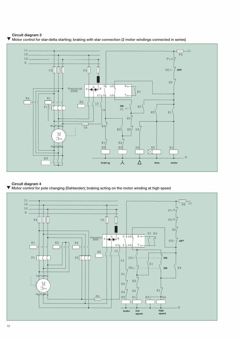
12
Circuit diagram 4Motor control for pole changing (Dahlander); braking acting on the motor winding at high speed
▲
Circuit diagram 3Motor control for star-delta starting; braking with star connection (2 motor windings connected in series)
▲

13
Circuit diagram 5Motor control for pole changing; braking acting on the motor winding at high speed
Circuit diagram 62-motor control; braking with series connection for motors >2 kW
▲
▲

14
choke type Order For brake unit Dimensions Weight (kVA) number current (A) (h x w x d) (mm) (kg)
KS 0.05 00100005 up to 36 65 x 75 x 110 1.3KS 0.075 00100075 up to 60 90 x 75 x 110 1.5KS 0.25 00100250 up to 150 135 x 95 x 160 3.8KS 0.5 00100500 up to 200 140 x 120 x 180 5.5KS 1.0 00101000 up to 300 125 x 150 x 210 12.0KS 1.6 00110160 up to 400 220 x 130 x 265 16.0KS 2.0 00110200 up to 500 240 x 160 x 300 25.0KS 3.0 00110300 up to 750 240 x 160 x 300 25.0KS 4.0 00110400 up to 1500 240 x 235 x 300 33.0
frenostat 2000 electronic brake units arepower converter units that operate directlyon the system using phase control.Suitable interference suppression toincrease noise immunity must be taken inelectric cabinets in line with the EU'sDirective on EMC, 89/336/EEC.
These suppressions must prevent notonly interference susceptibility, but alsoactual interference of adjacent sensitiveunits, such as PLCs, frequency converters
or other microprocessor-based controllersthat are connected to the same system.This necessitates the use of a line choke,which prevents system perturbation andprotects the brake unit against resonantvoltage peaks.
The line choke must be connected to lineterminal 8 (L1) of the brake unit. The reactoris already integrated into Size 2 frenostat2000 brake units (see page 10).
Accessory:line choke
▲Line choke selection table for frenomat and frenostat brake units
Circuit diagram 72-motor control; braking with parallel connection for motors <2 kW
▲

Commissioningfrenomat 2/frenostat 2000 electronic brake units
N.B.
Activating withoutbraking current
Test interlocking
Motor contactor K 1 on
Braking contactor K 2 off - K 1 locked
Test interlock: Energize K 2 by hand Energize K 1 by handK 1 de-energizes K 2 de-energizes
On
K 1 cannot be energized,On interlocked
15
Remove the fuse from the motor. Set poten-tiometer “T” (time) to max. (turn clockwiseas far as it will go) and potentiometer “I”
(current) to min. (turn counterclockwise asfar as it will go).
Off
Off
• Electronic printed-circuit boards are live.• Connect heat sinks to ground.• Avoid using a long supply lead.• Use an ohmmeter or multimeter.
Do not use a continuity tester or test lamp.
AustraliaFraser, Hrones & Co.PTY.ltd.NSW 2103 Mona ValeUnit 36, 12-14 Waratah StreetPhone: 00612 / 99796333
Italyintecno SRL Via Caduti di Sabbiuno, 9/E 40011 Anzola Emilia (BO) Fon: 0039 051 19985350
SpainHermann-Otto Suderow S.L.Apartado 13548930 Las Arenas (Vizcaya)Phone: 00349 / 44800018
FinlandOY HedTec ABPostfach 110201 HelsinkiPhone: 00358 / 968281
NetherlandsBakker & Co.B.V.Postbus 12353330 CE ZwijndrechtPhone: 0031 / 786101666
Czech RepublicELGO Electric s.r.oKourimska 10328000 Kolin 1Phone: 00420 / 32124489
Great BritainStromag Ltd.29 Wellingborough RoadRushden, Northants NN10 9YEPhone: 0044 / 193350407
FranceDOPAG S.a.r.L.B.P. 64 26903 ValencePhone: 0033 / 475419060
Throw the motor fuse and turn poten-tiometer “T” (time) through a 1/4 turn. Whenthe motor has reached its normal operatingtemperature, slowly turn potentiometer “I”(current) clockwise during braking andobserve the current value on the LED bardisplay while doing so. 10 bars = 100%indication = rated current of the unit.During braking, LEDs “B” (braking) and “S”(standstill) light up. “B” indicates energizingof the output relays on terminals 3 and 4and “S” monitors the rotation of the motor(On) until the standstill (Off).
LED “S” is off when braking is completed.The braking time set at potentiometer “T”(time) accumulates automatically. This canbe set manually for post-braking that canlast up to 20 seconds.LED “O” (overheating) flashes if the heatsinks of the brake unit have become toohot due to too frequent braking. The motorcannot start again as long as this LEDflashes.frenostat 1000 and frenomat are notequipped with overheating protection.
▲
With frenostat 1000 : connect a DC -ammeter to terminal T2.With frenomat – 2 : connect a DC ammetertpo terminal b.
International sales organization
Setting the braking current
Note
Operating principle

Hilger u. Kern GmbH · Käfertaler Straße 253 · 68167 Mannheim · DEUTSCHLAND Phone: +49 (0)621 / 37 05 - 0 · Fax: +49 (0)621 / 37 05 - 402 · E-mail: [email protected] · Home: www.hilger-kern.com ©
by
Hilg
er u
. Ker
n In
dus
trie
elek
tron
ik -
Sub
ject
to
chan
ge w
ithou
t p
rior
notic
e -
201
5.04
pd
f.
Hilger u. Kern Industrieelektronik
Dopag HeadquartersSwitzerland
Dopag SCAN ApsDenmark
Dopag UK Ltd.England
Dopag S.A.R.L.France
Dopag SDN. BHDMalaysia
Dopag Sverige ABSweden
The Hilger u. Kern / Dopag Group, which employs a workforce of more than 320 and has 6 international
subsidiaries, is one of the world's largest manufacturers of metering and mixing systems, systems that
deploy all processing concepts commonly in use for polymers and single-component media such as
greases, oils and adhesives.
The Group has been developing and building machines, installations and one-off units tailored specifically
to your requirements for more than 25 years.
Comprising 4 separate divisions specializing in Drive Technology, Metering Technology, Industrial
Electronics and Spray Technology, Hilger u. Kern Industrietechnik, located in Mannheim, is one Ger-
many's leading manufacturers of technically sophisticated, innovative and high-quality capital goods.
Hilger u. Kern GmbHGermany
Drive Technology
Friction-locking and positive drive systemsPlanetary gearing
Metering Technology
Mixing and metering systems forpolymers and 1-component media
Industrial Electronics
Electronic softstarters and brake units, microcomputers,machine monitoring systems
Spray Technology
Spray system, material supply, customized systems