friction anisotropy driven domain imaging on exfoliated...
TRANSCRIPT

Suswapna Patnaik,9 Rosa Quan,6 Gopalakrishna Ramaswamy,9#Paul Shinn,6 Geetha M. Swamilingiah,9 Stacy Wu,6 Joseph R.Ecker6,7† (chair).Interactome data acquisition group: Matija Dreze1,2,5 (projectleader), Danielle Byrdsong,1,2 Amélie Dricot,1,2 Melissa Duarte,1,2
Fana Gebreab,1,2 Bryan J. Gutierrez,1,2 Andrew MacWilliams,1,2
Dario Monachello,12** M. Shahid Mukhtar,11†† Matthew M.Poulin,1,2 Patrick Reichert,1,2 Viviana Romero,1,2 Stanley Tam,1,2
Selma Waaijers,1,2‡‡ Evan M. Weiner,1,2 Marc Vidal1,2† (co-chair), David E. Hill1,2† (co-chair), Pascal Braun1,2† (chair).wNAPPA interactome validation group: Mary Galli6 (projectleader), Anne-Ruxandra Carvunis,1,2,3 Michael E. Cusick,1,2 MatijaDreze,1,2,5 Viviana Romero,1,2 Frederick P. Roth,1,8‡ MuratTasan,8 Junshi Yazaki,7 Pascal Braun1,2† (co-chair), Joseph R.Ecker6,7† (chair).Bioinformatics and analysis group: Anne-RuxandraCarvunis1,2,3 (project leader), Yong-Yeol Ahn,1,10 Albert-LászlóBarabási,1,10 Benoit Charloteaux,1,2,4 Huaming Chen,6 Michael E.Cusick,1,2 Jeffery L. Dangl,11 Matija Dreze,1,2,5 Joseph R. Ecker,6,7†Changyu Fan,1,2 Lantian Gai,6 Mary Galli,6 Gourab Ghoshal,1,10
Tong Hao,1,2 David E. Hill,1,2† Claire Lurin,12 Tijana Milenkovic,13
Jonathan Moore,14 M. Shahid Mukhtar,11†† Samuel J.Pevzner,1,2,15,16 Natasa Przulj,17 Sabrina Rabello,1,10 Edward A.Rietman,1,2§§ Thomas Rolland,1,2 Frederick P. Roth,1,8‡ BalajiSanthanam,1,2 Robert J. Schmitz,7 William Spooner,18,19 JoshuaStein,18 Murat Tasan,8 Jean Vandenhaute,5 Doreen Ware,18,20
Pascal Braun1,2† (co-chair), Marc Vidal1,2† (chair).Writing group: Pascal Braun1,2† (chair), Anne-RuxandraCarvunis,1,2,3 Benoit Charloteaux,1,2,4 Matija Dreze,1,2,5 MaryGalli,6 Marc Vidal1,2† (co-chair).
1Center for Cancer Systems Biology (CCSB) and Departmentof Cancer Biology, Dana-Farber Cancer Institute, Boston, MA02215, USA. 2Department of Genetics, Harvard Medical School,
Boston, MA 02115, USA. 3Computational and MathematicalBiology Group, Techniques de l’Ingénierie Médicale et dela Complexité–Informatique, Mathématiques et Applica-tions de Grenoble, CNRS UMR5525 and Université deGrenoble, Faculté de Médecine, 38706 La Tronche Cedex,France. 4Unit of Animal Genomics, GIGA-R and Faculty ofVeterinary Medicine, University of Liège, 4000 Liège, Wallonia-Brussels Federation, Belgium. 5Unité de Recherche en BiologieMoléculaire, Facultés Universitaires Notre-Dame de la Paix,5000 Namur, Wallonia-Brussels Federation, Belgium. 6GenomicAnalysis Laboratory, Salk Institute for Biological Studies, LaJolla, CA 92037, USA. 7Plant Biology Laboratory, Salk Insti-tute for Biological Studies, La Jolla, CA 92037, USA. 8Depart-ment of Biological Chemistry and Molecular Pharmacology,Harvard Medical School, Boston, MA 02115, USA.
9
LifeTechnologies, Carlsbad, CA 92008, USA. 10Center forComplex Network Research (CCNR), Department of Physics,Northeastern University, Boston, MA 02115, USA. 11Depart-ment of Biology, University of North Carolina at Chapel Hill,Chapel Hill, NC 27599, USA.
12
Unité de Recherche enGénomique Végétale, Unités Mixtes de Recherche InstitutNationale de la Recherche Agronomique/Université Evry-Vald’Essonne ERL Centre National de la Recherche Scientifique91057, Evry Cedex, France. 13Department of Computer Scienceand Engineering, University of Notre Dame, Notre Dame, IN46556, USA. 14Warwick Systems Biology Centre, CoventryHouse, University of Warwick, Coventry, CV4 7AL, UK.15Biomedical Engineering Department, Boston University,Boston, MA 02215, USA. 16Boston University School ofMedicine, Boston, MA 02118, USA. 17Department of Comput-ing, Imperial College London, London SW7 2AZ, UK. 18ColdSpring Harbor Laboratory, Cold Spring Harbor, NY 11724, USA.19Eagle Genomics Ltd., Babraham Research Campus, Cam-bridge, CB4 1JD, UK. 20United States Department of Ag-
riculture, Agricultural Research Service, Robert W. HolleyCenter for Agriculture and Health, Cornell University, Ithaca,NY 14853, USA.
‡Present address: Donnelly Centre for Cellular and Biomolec-ular Research, University of Toronto, Toronto, Ontario M5S3E1,Canada and Samuel Lunenfeld Research Institute, Mt. SinaiHospital, Toronto, Ontario M5G1X5, Canada.§Present address: Foley & Lardner LLP, 3579 Valley CentreDrive, Suite 300, San Diego, CA 92130, USA.||Deceased.¶Present address: Pacific Biosciences, 940 Hamilton Drive,Menlo Park, CA 94025, USA.#Present address: Thermo Fisher Scientific, BioSciences Di-vision, Bangalore-560011, India.**Present address: Centre de Génétique Moléculaire du C.N.R.S.,1 Avenue de la Terrasse, 91190 Gif-sur-Yvette, France.††Present address: Department of Biology, University of Ala-bama at Birmingham, Birmingham, AL 35294, USA.‡‡Present address: University of Utrecht, 3508 TC Utrecht,The Netherlands.§§Present address: Center of Cancer Systems Biology,St. Elizabeth's Medical Center, Tufts University School ofMedicine, Boston, MA 02135, USA.
Supporting Online Materialwww.sciencemag.org/cgi/content/full/333/6042/601/DC1SOM TextFigs. S1 to S47Tables S1 to S12References
7 February 2011; accepted 10 June 201110.1126/science.1203877
REPORTS
Friction Anisotropy–DrivenDomain Imaging on ExfoliatedMonolayer GrapheneJin Sik Choi,1 Jin-Soo Kim,1 Ik-Su Byun,1 Duk Hyun Lee,1 Mi Jung Lee,1 Bae Ho Park,1*Changgu Lee,2 Duhee Yoon,3 Hyeonsik Cheong,3 Ki Ho Lee,4 Young-Woo Son,4
Jeong Young Park,5* Miquel Salmeron6
Graphene produced by exfoliation has not been able to provide an ideal graphene withperformance comparable to that predicted by theory, and structural and/or electronic defectshave been proposed as one cause of reduced performance. We report the observation of domainson exfoliated monolayer graphene that differ by their friction characteristics, as measured byfriction force microscopy. Angle-dependent scanning revealed friction anisotropy with a periodicityof 180° on each friction domain. The friction anisotropy decreased as the applied loadincreased. We propose that the domains arise from ripple distortions that give rise to anisotropicfriction in each domain as a result of the anisotropic puckering of the graphene.
Themechanical exfoliation method to trans-fer a monolayer of graphene to a substrateis thought to be a facile method to obtain
a single crystalline graphene (1). Mechanicalexfoliation, however, may induce strain on thegraphene layer during deposition on a substrateand can create wrinkled films and other defects,because the interaction with the substrate mightintroduce uneven compressive and tensile stressesthat are nonuniformly distributed across the film.Structural defects such as atomic defects (2), wrin-
kles or ripples (3–5), and microscopic corruga-tion (6) have already been reported on supportedgraphene. These defects tend to lower the elec-trical performance of graphene devices becausethey break translational or rotational symmetry.In addition, the boundaries of microscale domainsalso break the symmetry, as reported for graphenegrown by chemical vapor deposition (7). How-ever, no experimental observations of microscaledomains on mechanically exfoliated monolayergraphene have been reported to date.
Atomic force microscopy (AFM) can be usedto study the mechanical properties of surfaces be-cause it provides local information about hard-ness, deformation, slipperiness, and chemicalstate. Friction force microscopy (FFM) has beenused to investigate elastic deformation, atomicstructure, dislocation, and defects (8, 9). Recentstudies show that friction depends on the num-ber of graphene layers as well as the nature of thegraphene-substrate bond (10–12). Puckering in-duced by AFM tip scanning has been proposedas the origin of the thickness effects on friction(10). Here, we show the existence of domains onexfoliated monolayers of graphene deposited onsilicon oxide that are distinguished by their dif-ferent friction characteristics when an AFM tipslides over them. These domains cannot be ob-served in AFM topographic images, optical mi-croscopy, or micro-Raman spectroscopy.
1Division of Quantum Phases and Devices, Department ofPhysics, Konkuk University, Seoul 143-701, Korea. 2Depart-ment of Mechanical Engineering, Sungkyunkwan University,Suwon 440-746, Korea. 3Department of Physics, Sogang Uni-versity, Seoul 121-742, Korea. 4Korea Institute for AdvancedStudy, Seoul 130-722, Korea. 5Graduate School of Energy, En-vironment, Water, and Sustainability, NanoCentury KI, KoreaAdvanced Institute of Science and Technology, Daejeon 305-701,Korea. 6Materials Science Division, Lawrence Berkeley NationalLaboratory, Berkeley, CA 94720, USA.
*To whom correspondence should be addressed. E-mail:[email protected] (B.H.P.); [email protected]( J.Y.P.)
www.sciencemag.org SCIENCE VOL 333 29 JULY 2011 607
on
Aug
ust 2
, 201
1w
ww
.sci
ence
mag
.org
Dow
nloa
ded
from

The black dashed lines in the AFM topog-raphy and optical microscopy images in Fig. 1, Aand B, delineate a single graphene layer. To con-firm the number of graphene layers, we performedmicro-Raman spectroscopy at the six points indi-cated in Fig. 1B (13). The 2D band (~2686 cm−1)has a single Lorentzian 2D line shape, and thereis no D peak, the presence of which is associ-ated with disordered carbon atoms or defects(Fig. 1C). Moreover, there are no appreciable
variations in the Raman spectra, which indicatesthat the graphene layer does not have charge dop-ing variations or high-strain domains. The expandedAFM topographic image in Fig. 1D, correspond-ing to the red dashed square in Fig. 1A, shows thetopographic uniformity of the graphene layer.
Although the topographic image is completelyuniform, a striking result was obtained in simul-taneously acquired friction force images, whichreveal the existence of several domain structures
in the same layer with different friction proper-ties (Fig. 1E). Figure 1F shows the FFM line pro-files in forward and backward scans along theblack dashed line shown in Fig. 1E. The differencebetween the friction signals in the two scan direc-tions is proportional to the friction force. Suchfrictional domains in single layers were frequentlyobserved in other graphene layers that we mea-sured, both in air and in high-vacuum environ-ments (~10−4 torr).
A B
D
C
1200 1600 2000 2400 2800
Ram
an in
tens
ity (
arb.
uni
ts)
Raman shift (cm-1)
G*
2D
G
1550 1600
G band
2650 2700 2750
2D band
E F
5 µm
SiO2
Monolayergraphene
1 µm
SiO2
Monolayergraphene
0 1 2 3 4 5
Fric
tion
sign
al (
arb.
uni
ts)
Distance (µm)
SiO2 I III II
Forward scan
Backward scan
Fig. 1. Frictional domains on a monolayer graphene flake. (A) AFM to-pography, (B) optical microscopy image, and (C) Raman spectra at thesix points marked in (B). The two inset graphs show detailed shapes ofG-band and 2D-band peaks. (D and E) Expanded AFM topographic and
friction force images, respectively, of the red dashed square in (A).The red arrow indicates the forward scanning direction. (F) Frictionforce traces from forward and backward scans along the black dashedline in (E).
0 60 120 1800.0
0.1
0.2
0.3
0.4
experiments : I II III fittings : I II III
Fric
tion
(a.u
.)
Rotation Angle (θ)
F2
F1
A B16° 27° 46°
60° 73° 85° 94°
126° 141°
165° 184°
I
IIIII
0°
1 µm
Fig. 2. (A) Friction force images showing the changing frictioncontrast as the sample is rotated counterclockwise from 0° to184° relative to the horizontal scan direction (red dashed arrow).Roman numerals indicate the three friction domains identified inFig. 1E. (B) Normalized friction force versus rotation angle for eachdomain, showing 180° periodicity. The lines show that the varia-tions in friction can be fitted by a simple sine modulus function.
29 JULY 2011 VOL 333 SCIENCE www.sciencemag.org608
REPORTS
on
Aug
ust 2
, 201
1w
ww
.sci
ence
mag
.org
Dow
nloa
ded
from

Another surprising result is that the frictionforce in each domain showed a peculiar 180°periodic dependence on the angle between thescan direction and sample orientation (Fig. 2).The images in Fig. 2A were obtained by incre-mentally rotating the sample while keeping thescan direction along the horizontal axis (red dashedarrow) fixed. The brighter areas correspond togreater friction. During these measurements, theloading force (0 nN), scan area (5 mm by 5 mm),and scanning speed (0.5 Hz) were kept fixed. Thedifferent friction measured in each domain is notcaused by any interaction with the silicon ox-ide substrate, which has been shown to be two-dimensionally isotropic (14). Nor can it be dueto different local chemical properties, because thetip-surface adhesion was found to be the same ineach domain within the error bar. The values for
work of adhesion measured on domains I, II, andIII were 7.3 T 0.2, 7.4 T 0.2, and 7.6 T 2.3 mJ/m2,respectively, as derived from the Derjaguin,Muller, and Toporov (DMT) model with a tipradius of 100 nm. These are all smaller than thework of adhesion measured on the bare siliconoxide surface (9.2 T 0.8 mJ/m2).
Figure 2B shows normalized friction dataversus sample rotation angle (q) for each do-main. Normalization was performed by subtract-ing the forward and backward friction signalson each domain, followed by dividing this val-ue by the corresponding value on the surround-ing SiO2 area, which is independent of thescanning direction.
The 180° angular periodicity of the frictioncannot be the result of the hexagonal periodicityof graphene, which would give rise to a period of
60°. Instead, the observed periodic friction in eachdomain can be fit with a simple sinusoidal curveof the type Fi(q) = F1 + (F2 − F1) × |sin(q – qi)|,where the phase term qi for each domain is de-termined from fitting the experimental data inFig. 2B.F1 andF2 are the friction forceminimumand maximum values, respectively. From this fit,we obtain a friction anisotropy ratioF2/F1 of 2.15 T0.08, which is the same for each domain, indicat-ing a common origin of the friction anisotropy.
We also investigated the dependence of fric-tion on applied load. As shown in Fig. 3A, thefriction force on the SiO2 substrate shows a goodfit to the DMT model, which is applicable tohard bulk materials (15). The friction value at aloading force of –2 nN confirms that the tip-surface adhesion force on SiO2 and monolayergraphene is between –1 nN and –2 nN. Figure3B shows the effect of applied load on the ratioof the friction in I (maximum) and III (minimum)domains for a fixed scan direction. The ratio de-creases gradually as the load increases until it fi-nally converges to 1when the applied load reaches5 nN or higher. Because domain II is oriented in adiagonal direction with respect to the ripple lineand exhibits an intermediate friction value, the ef-fect of applied load on the ratio of the friction inthe I (maximum) and II (medium) domains is notas prominent.
Friction anisotropy has been previously ob-served on various systems and rationalized in termsof lattice commensurability arguments (16), dif-ferences in phonon excitation probability alongdifferent crystallographic directions (17), and an-isotropic deformation in films of organicmolecules(18, 19). Our results, however, show frictionaldomains with an anisotropy period of 180°, un-related to the 60° angle between principal crystal-lographic directions of graphene. Having excludedthe substrate influence as well as electronic andchemical effects, we are led to assign the frictiondifferences in the domains to out-of-plane elasticpuckering, as proposed by Lee et al. (10), result-ing from differently oriented ripple structures inthe graphene layer in each domain (Fig. 4).
We propose that the ripple structure is the re-sult of inhomogeneous interactions of the graphenewith the SiO2 substrate, which causes stress-induceddeformations in the form of ripples along the stiffdirections of the graphene lattice, presumably thearmchair or zigzag directions (20, 21). This ex-plains the 60° oriented frictional domains shownin Fig. 2B. Ripple structures were also reported byMorozov et al. and are related to the impossibilityof simultaneously attaching graphene to the sub-strate over the entire surface during mechanicalexfoliation (22).
Rippled graphene under unidirectional strainwill have anisotropic bending stiffness dependingon the direction. If the tip scans along the rippleline, bending (or puckering) of the graphene isprohibited because deformation resistance is high-er along the direction perpendicular to the strain.In contrast, for perpendicular scanning, bendingis enhanced, leading to an increased contact area
-2 0 2 4 6
1.0
1.5
2.0
Fric
tion
(I)
/ fric
tion
(III
)
Applied load (nN)
A B
-2 0 2 4 6
0
2
4
Fric
tion
(a.u
.)
Applied load (nN)
SiO2 DMT
fitting
I II III
-2 0 2 4 60.0
0.4
0.8
I II III
Fig. 3. (A) Friction force dependence on applied load for each domain and for the bare SiO2 substrate.(B) Effect of applied load on the friction ratio between domains I and III for a fixed scan direction.
Fig. 4. Schematic diagrams illustrating the model used to explain the existence of friction domains andthe 180° period friction anisotropy. The model is based on the existence of graphene ripples originatedby the inhomogeneous pinning of the flake to the SiO2 substrate. The model assumes that the rippleline follows directions of high stiffness in the graphene (e.g., the armchair or zigzag directions). (A)Illustration of three ripple domains. (B) Definition of the relative angle (Q) between scan direction andthe ripple lines. (C) Illustration of the puckering effect when the tip deforms the graphene layer by thelateral force exerted along the scan direction. The puckering effect depends on the applied load.
www.sciencemag.org SCIENCE VOL 333 29 JULY 2011 609
REPORTS
on
Aug
ust 2
, 201
1w
ww
.sci
ence
mag
.org
Dow
nloa
ded
from

between the tip and graphene. Puckering deforma-tion due to the tip pushing the ripple crest forwardalong the scanning direction explains the 180°anisotropy. Therefore, if Q is the relative anglebetween the ripple line and the scan direction, wecan then expect minima and maxima separatedby 90° with an angular dependence following a|sin Q| relation, because the in-plane force com-ponent along the direction perpendicular to theripple line of the AFM tip varies in this way.
A high loading force induces a large contactarea (100 to 1000 nm2), which can decrease therelative contribution of ripple deformations tothe friction and thus the dependence on Q. Thisis because puckering takes place at the exposedgraphene in contact proximity to the tip (Fig. 4C).Although the contact area increases at the highload, the contribution of the ripple deformationaround the tip in relation to the contact area de-creases, and thus the bending of graphene becomesless dependent on the scan direction. We canexpect, therefore, more isotropic puckering andfriction at the high load. High-resolution frictionimages showed the existence of lattice distortionsthat could be associated with the puckering (fig.S1). These distortions were not observed on bulkgraphite images obtained under identical condi-tions. Because bulk graphite can be consideredan extremely thick graphene, such distortion as-sociated with puckering seems to decrease as thegraphene thickness increases.
As a further test of this model, we performedFFM measurements on a graphene sheet acci-dentally deposited over a particle in the sub-strate. The images revealed mechanical wrinklesand friction domains induced by stress in theproximity of the particle (figs. S2 and S3). Ripples
created by the radial stress around the particleare manifested in the formation of domains ex-hibiting friction anisotropy with similar 180° pe-riodicity (Fig. 2). The 60° shift between ripplelines of adjacent domains supports our assump-tion that the ripple lines are related to the crys-tallographic direction of the graphene. The frictioncontrast in the domains also became weaker af-ter thermal annealing at 200°C and disappearedcompletely after annealing at 400°C (fig. S4).The initial anisotropy was a characteristic of thegraphene flake previous to equilibration. Becausetwo-dimensional structured graphene has a neg-ative thermal expansion coefficient, heating andcooling processes can restore the graphene toequilibrium, changing a stress-induced ripple (4).
Our results indicate that friction mapping onthe graphene layer constitutes a powerful tool tostudy the ripple structure formed on grapheneduring mechanical exfoliation processes. Anoth-er interesting outcome of our research is that thecontrol of friction and anisotropic mechanicalproperties, such as the one presented here with alarge anisotropy ratio of 215%, could be ex-ploited in solid lubrication of micro- or nano-electromechanical systems.
References and Notes1. K. S. Novoselov et al., Science 306, 666 (2004).2. A. Hashimoto, K. Suenaga, A. Gloter, K. Urita, S. Iijima,
Nature 430, 870 (2004).3. A. Fasolino, J. H. Los, M. I. Katsnelson, Nat. Mater. 6, 858
(2007).4. W. Bao et al., Nat. Nanotechnol. 4, 562 (2009).5. K. Xu, P. Cao, J. R. Heath, Nano Lett. 9, 4446
(2009).6. C. H. Lui, L. Liu, K. F. Mak, G. W. Flynn, T. F. Heinz,
Nature 462, 339 (2009).7. P. Y. Huang et al., Nature 469, 389 (2011).
8. J. Y. Park, P. A. Thiel, J. Phys. Condens. Matter 20,314012 (2008).
9. C. Lee et al., Phys. Status Solidi B 246, 2562 (2009).10. C. Lee et al., Science 328, 76 (2010).11. H. Lee, N. Lee, Y. Seo, J. Eom, S. W. Lee, Nanotechnology
20, 325701 (2009).12. T. Filleter et al., Phys. Rev. Lett. 102, 086102 (2009).13. A. C. Ferrari et al., Phys. Rev. Lett. 97, 187401 (2006).14. J. Y. Park, D. F. Ogletree, P. A. Thiel, M. Salmeron,
Science 313, 186 (2006).15. D. S. Grierson, E. E. Flater, R. W. Carpick, J. Adhes. Sci.
Technol. 19, 291 (2005).16. M. Dienwiebel et al., Phys. Rev. Lett. 92, 126101 (2004).17. J. Y. Park et al., Science 309, 1354 (2005).18. M. Liley et al., Science 280, 273 (1998).19. R. W. Carpick, D. Y. Sasaki, A. R. Burns, Tribol. Lett. 7, 79
(1999).20. K. Min, N. R. Aluru, Appl. Phys. Lett. 98, 013113 (2011).21. A. Sakhaee-Pour, Solid State Commun. 149, 91 (2009).22. S. V. Morozov et al., Phys. Rev. Lett. 97, 016801
(2006).Acknowledgments: Supported by the National Research
Foundation of Korea funded by the Ministry of Education,Science, and Technology (National Research Laboratoryprogram grant 2008-0060004; World Class Universityprogram grants R31-2008-000-10057-0 and R31-2008-000-10055-0; Basic Science Research program grantsKRF-2008-314-C00111, KRF-2010-0005390, 2010-0015035,2011-0014209, and 2011-0017605; and QuantumMetamaterials Research Center grant R11-2008-053-03002-0).M.B.S. was supported by the Office of Basic Energy Sciences,Division of Materials Sciences and Engineering, U.S.Department of Energy, under contract DE-AC02-05CH11231.J.S.C. was supported by a Hi Seoul Science/HumanitiesFellowship from the Seoul Scholarship Foundation.
Supporting Online Materialwww.sciencemag.org/cgi/content/full/science.1207110/DC1Materials and MethodsFigs. S1 to S4References
18 April 2011; accepted 16 June 2011Published online 30 June 2011;10.1126/science.1207110
Synthesis and Characterization of aNeutral Tricoordinate OrganoboronIsoelectronic with AminesRei Kinjo,1 Bruno Donnadieu,1 Mehmet Ali Celik,2 Gernot Frenking,2 Guy Bertrand1*
Amines and boranes are the archetypical Lewis bases and acids, respectively. The former canreadily undergo one-electron oxidation to give radical cations, whereas the latter are easilyreduced to afford radical anions. Here, we report the synthesis of a neutral tricoordinateboron derivative, which acts as a Lewis base and undergoes one-electron oxidation into thecorresponding radical cation. These compounds can be regarded as the parent borylene (H-B:)and borinylium (H-B+.), respectively, stabilized by two cyclic (alkyl)(amino)carbenes. Ab initiocalculations show that the highest occupied molecular orbital of the borane as well as the singlyoccupied molecular orbital of the radical cation are essentially a pair and a single electron,respectively, in the p(p) orbital of boron.
The chemistry of boron is dominated bycompounds in which the element adoptsthe +3 oxidation state and acts as a potent
electron pair acceptor, or Lewis acid. To com-pensate its intrinsic electron deficiency, boronalso often participates in multicenter bonds, and
numerous clusters involving hypervalent boroncenters are known (1). At the opposite extreme,it is only recently that low-valent boron deriv-atives have been thoroughly explored (2–9).Among these species, borylenes (BR), the sub-valent boron(I) derivatives analogous to carbenes
(CR2) and nitrenes (NR), have been spectro-scopically characterized in solid inert gas matri-ces at temperatures of a few K (10, 11) but todate have eluded preparative isolation. Nonethe-less, Braunschweig et al. (12) have shown thatborylenes can be incorporated into the ligandsphere of stable, isolable transition metal com-plexes (13).
In recent years, stable singlet carbenes suchas N-heterocyclic carbenes (NHCs) (14, 15) andcyclic (alkyl)(amino)carbenes (CAACs) (16) haveproven as powerful as transition metal centersfor stabilizing highly reactive main group elementspecies (17, 18). In the boron series, Robinsonand co-workers (19, 20) have reported that re-duction of the (NHC)BBr3 adduct A producedthe isolable stable neutral diborene B, which canbe regarded as a dimer of the parent borylene-
1UCR-CNRS Joint Research Chemistry Laboratory (UMI 2957),Department of Chemistry, University of California Riverside(UCR), Riverside, CA 92521–0403, USA. 2Fachbereich Chemie,Philipps-Universitat Marburg, Hans-Meerwein-Strasse, 35032Marburg, Germany.
*To whom correspondence should be addressed. E-mail:[email protected]
29 JULY 2011 VOL 333 SCIENCE www.sciencemag.org610
REPORTS
on
Aug
ust 2
, 201
1w
ww
.sci
ence
mag
.org
Dow
nloa
ded
from
www.sciencemag.org/cgi/content/full/science.1207110/DC1
Supporting Online Material for
Friction Anisotropy–Driven Domain Imaging on Exfoliated Monolayer
Graphene
Jin Sik Choi, Jin-Soo Kim, Ik-Su Byun, Duk Hyun Lee, Mi Jung Lee, Bae Ho Park,* Changgu Lee, Duhee Yoon, Hyeonsik Cheong, Ki Ho Lee, Young-Woo Son, Jeong Young Park,*
Miquel Salmeron
*To whom correspondence should be addressed. E-mail: [email protected] (B.H.P.); [email protected] (J.Y.P.)
Published 30 June 2011 on Science Express DOI: 10.1126/science.1207110
This PDF file includes: Materials and Methods Figs. S1 to S4 References

Materials and Methods Sample preparation and identification of thickness Graphene flakes were deposited, using the standard mechanical exfoliation method, onto thermally grown silicon dioxide (SiO2: 300 nm) substrates at ambient conditions without any further treatment. Thin graphene samples were sorted using optical microscopy. The number of graphene layers was then measured by Raman spectroscopy, with the 514.5-nm laser line of an Ar ion laser used as an excitation source. AFM measurement conditions AFM topography and FFM images were simultaneously obtained in contact mode with a Seiko SPA-300HV AFM at ambient conditions. We also obtained FFM images under high vacuum with a base pressure of 6.3×10⁻⁶ torr to check the effect of humidity on friction data. We used silicon AFM tips [Nanosensors PPP-LFMR with spring constant of 0.2 N/m] for micrometer-scale contact imaging, and diamond-like carbon tips [NT-MDT NSG01_DLC with the spring constant of 2.5 to 10 N/m] for nano-scale lattice resolution imaging. The topographic images were processed by line and plane subtraction corrections to compensate for scanning drift. The scan direction of the FFM images, including stick-slip lattice resolved images, was perpendicular to the cantilever body length direction (0 or 180°; forward scan or backward scan, respectively). The graphene sample was rotated to check the dependence of the FFM images on scan direction. Friction domain images have been observed reproducibly in isolated monolayer graphene samples with various sizes and shapes, which are fabricated using the mechanical exfoliation method. We obtained these results with various tips, including silicon and silicon nitride coated tips with a low spring constant to maintain friction force sensitivity. Furthermore, the results can be observed with a couple of AFM systems (PSIA XE-100 and Seiko SPA-300HV). Lattice structure measured from atomic stick-slip friction High-resolution imaging measurements in FFM mode were done at a scan speed of 45 nm/s for a 1.5-nm scan size, as shown in Fig. S1. Using a low pass filtered image obtained through fast Fourier transform (FFT), we can analyze the periodic crystal structure of graphite and graphene with three frictional domains (I, II, and III) (1). Graphene shows three differently distorted hexagonal crystal structures for each frictional domain. In order to compare the lattice dimensions, a blue dotted circle drawn over the hexagonal hollow sites of C near neighbors in graphite is overlaid on the distorted hexagonal atomic structures found in each domain (third row in Fig. S1). As can be seen, there is an observable distortion in the domains compared to graphite, with a different extent of
distortion in each domain. We propose that the distorted rings in the graphene are the result of both stress-induced ripple structures and puckering during imaging (2), since bulk graphite shows different data with hexagonal symmetry. Local sliding of graphene flakes has been previously observed on graphite (3,4). A similar process during sliding over the rippled areas can also give rise to distorted stick-slip. Figure S1 also shows the nano-scale friction curves for graphite and graphene. The difference between forward and backward scans is proportional to the friction force value. Formation of frictional domains near a particle Figure S2A shows a tapping mode AFM topography image of a monolayer graphene that overlays a particle. Wrinkle structures can be observed emanating from the particle. The FFM images show friction domains in the vicinity of the particle, as shown in Fig. S2B. In order to investigate the friction anisotropy of each domain shown in Fig. S3A, we plotted the dependence of the normalized friction vs. rotation angle, as shown in Fig. S3B. The friction force on each domain can be fitted with the same function as that used for the data shown in Fig. 2B. The periodicity is 180° and friction anisotropy value is 2.13. There is also a 60° rotation angle shift between adjacent domains. We can assign the ripple directions in each domain based on the rotation angle dependence, as shown in the inset of Fig. S3A. Interestingly, the ripple directions are consistent with the wrinkle directions inside the domain. This result supports our model that the observed frictional domains and the friction anisotropy are strongly related to stress-induced ripple distortions. Thermal annealing effects on frictional domains Another interesting finding is that friction contrast between domains become weaker after thermal annealing at 200 °C and disappears completely after annealing at 400 °C, as shown in Fig. S4. The heating of the graphene film was carried out under high vacuum (~ 2.66 × 10⁻⁵ Torr) for 5min. These results provide additional support for our assumption that the frictional domains are the result of anisotropic stress during deposition and that thermal annealing can relieve this stress. Recently, W. Bao et al. showed that strain can be controlled by thermal manipulation of suspended graphene (5). Since graphene has a distinctive negative thermal expansion coefficient, the exfoliated graphene bonded to a SiO2/Si substrate might be expanded during thermal treatment. Therefore, this “ironing” process provides a method to eliminate the frictional domains. We are not sure at this point that such treatment will eliminate the friction anisotropy as well.
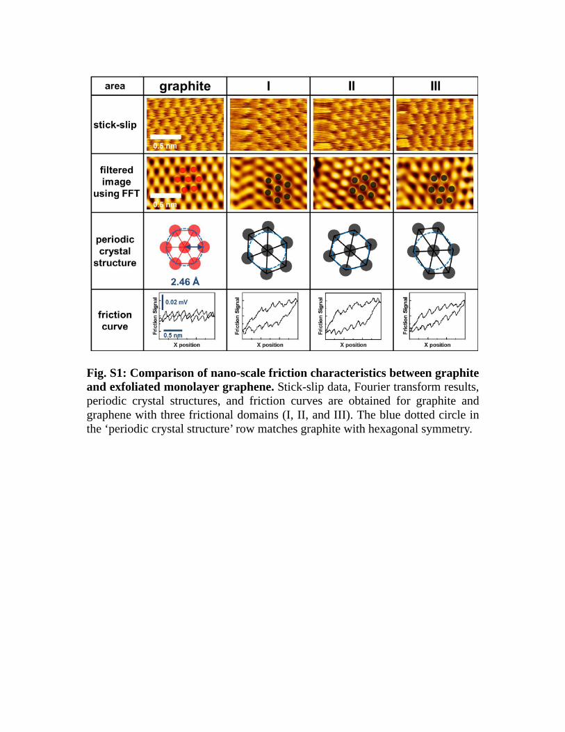
Fig. S1: Comparison of nano-scale friction characteristics between graphite and exfoliated monolayer graphene. Stick-slip data, Fourier transform results, periodic crystal structures, and friction curves are obtained for graphite and graphene with three frictional domains (I, II, and III). The blue dotted circle in the ‘periodic crystal structure’ row matches graphite with hexagonal symmetry.
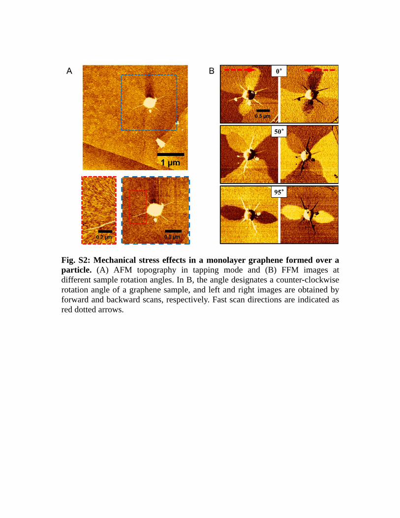
Fig. S2: Mechanical stress effects in a monolayer graphene formed over a particle. (A) AFM topography in tapping mode and (B) FFM images at different sample rotation angles. In B, the angle designates a counter-clockwise rotation angle of a graphene sample, and left and right images are obtained by forward and backward scans, respectively. Fast scan directions are indicated as red dotted arrows.

Fig. S3: Characteristics of frictional domain and friction anisotropy. (A) Frictional domain images near a particle and wrinkles and (B) dependence of normalized friction on sample rotation angle for each domain. The inset of A is a schematic diagram of the wrinkles and ripple lines. The lines in B show that the angle dependence of friction can be fitted by almost the same function with that used for the data shown in Fig. 2.

Fig. S4: Thermal annealing effects on frictional domains in a monolayer graphene. (A) Topography and (B) friction mapping (B) on as-deposited monolayer graphene before thermal annealing. The change in friction mapping after thermal annealing at (C) 200℃, and (D) 400℃ under high vacuum of ~ 2.66 × 10⁻⁵ Torr for 5 min.

References
1. H. Hölsher, U. D. Schwarz, O. Zwörner, R. Wiesendanger, Z. Phys. B 104,
295 (1997)
2. C. Lee, Q. Li, W. Kalb, X.-Z. Liu, H. Berger, R. W. Carpick, J. Hone, Science
328, 76 (2010)
3. M. Salmeron, Adhesion and friction at the atomic scale: Application of the
atomic force microscope. (Surface Diagnostics in Tribology:
Fundamental Principles and Applications. eds. K. Miyoshi and Y. W.
Chung. Pp. 75-91. World Scientific Publishing Co., River Edge. New
Jersey. 1993)
4. M. Salmeron, D. F. Ogletree, C. Ocal, H. –C. Wang, G. Neubauer, W. Kolbe,
G. Meyers, J. Vac. Sci. Technol. B. 9, 1347 (1991)
5. W. Bao, F. Miao, Z. Chen, H. Zhang, W. Jang, C. Dames, C. H. Lau, Nature
Nanotechnol. 4, 562 (2009)