friction surfacing with mg
DESCRIPTION
JOURNALSTRANSCRIPT
Some Characteristics of AZ31/AZ91 Dissimilar Magnesium Alloy Deposit
by Friction Surfacing
Dai Nakama*, Kazuyoshi Katoh and Hiroshi Tokisue
College of Industrial Technology, Nihon University, Narashino 275-8575, Japan
Monolayer friction surfacing was performed using a numerical controlled full automatic friction welding machine for AZ31 magnesiumalloy plate used for substrate and AZ91 magnesium alloy casting bar used for consumable rod. Effect of the surfacing conditions on structuresand mechanical properties of deposit were investigated. It was clearly observed that the circular pattern appeared on the surface of deposit by therotation of coating rod. Microstructures of deposit showed finer structure than that of both base metals, and the cast structure was disappeared.Hardness of the deposit showed higher value than that of the substrate. Wear resistance of the deposit was improved in comparison with thesubstrate. [doi:10.2320/matertrans.MC200779]
(Received October 5, 2007; Accepted January 28, 2008; Published March 12, 2008)
Keywords: friction surfacing, magnesium alloy, microstructures, hardness, wear test
1. Introduction
Friction surfacing is proposed as one of the surfacemodification methods to produce thick layer on the substrate.It is a solid state process with a frictional heat that bonds thecoating to the substrate without problems such as porositiesor slag inclusions.1) And the function by surfacing dissimilarmaterials to the material surface to be modified takes place insolid state. Therefore, minimal thermal effects on basematerials can be anticipated. The authors studied the effect ofsurfacing conditions on both the shape of deposit andmechanical properties of friction surfaced material combinedby aluminum alloy plate and bar.2,3) As a result, the thicknessof deposit was controlled if the appropriate surfacingconditions were chosen, and it was clarified that good depositwas obtained. The similar friction surfaced material using5052 aluminum alloy plate and bar was possible to form adeposit with the fine structure on the substrate. However,softening area has been observed in the vicinity of deposit onthe substrate.
It is significant to do surface modification by frictionsurfacing using a hard material without damaging a charac-teristic of matrix.
The authors studied the friction surfacing that is combinedby 5052 aluminum alloy plate and 2017 aluminum alloy bar.As the results, it was clarified that hard surface deposit wasobtained.3)
In the other, magnesium alloys increase their consumptionwith the purpose of light weighting, hence a study on thefriction surfacing of magnesium alloy is necessary, howeverthere are few studies on them.4) In addition, it is predicted thatfriction surfacing is difficult as for the magnesium alloywhich the movement of faying surface to the axial directionto be seen in stud friction welding is hard to produce.5)
In this study, dissimilar friction surfacing was conductedwith AZ31 magnesium alloy plate as a substrate and castAZ91 magnesium alloy bar as a coating material. Effect ofrotational speed of rod on the structures and mechanicalproperties of friction surfaced material has been studied.
2. Experimental Procedure
AZ31 magnesium alloy plate of 6mm thickness as asubstrate was machined to 50mm width and 150mm length.AZ91 magnesium alloy casting bar of 18mm diameter and100mm length was used as a consumable rod. Chemicalcompositions and mechanical properties of both base metalsare summarized in Table 1 and 2, respectively.
Friction surfacing was performed using a numericalcontrolled fully automatic friction welding machine. Thefriction surfacing was conducted by the restriction length ofconsumable rod (i.e., the surfacing was terminated when30mm of consumable rod was consumed or a maximum feedlength of 90mm in relation to the substrate.) was attained.By referring to the results of preliminary experiments,2,4)
the friction surfacing was performed under the surfacingconditions shown in Table 3.
Table 1 Chemical composition of base metals. (%)
Materials Al Zn Mn Si Cu Fe Ca Ni Mg
AZ91 8.83 0.62 0.20 0.01 0.002 — — Tr. Bal.
AZ31 3.5 1.3 1.0 0.05 0.05 0.005 0.04 0.005 Bal.
Table 2 Mechanical properties of base metals.
MaterialsTensile strength
(MPa)
Elongation
(%)
Hardness
(HK0.01)
AZ91 148 2.9 76.2
AZ31 244 16.8 51.1
Table 3 Friction surfacing conditions.
Rotation speed N (min�1) 1000, 1250, 1500
Friction pressure P (MPa) 40
Traverse speed f (mm/s) 5
Preheating time t (s) 5
*Graduate Student, Nihon University
Materials Transactions, Vol. 49, No. 5 (2008) pp. 1137 to 1141Special Issue on Platform Science and Technology for Advanced Magnesium Alloys, IV#2008 The Japan Institute of Metals

Observation of the appearances, macro- and microstruc-tures, hardness tests and wear test using an Ohgoshi-stylewear tester were conducted at room temperature. The countermaterial for the wear test with 30mm in diameter and 3mmin thickness was made of spheroidal graphite cast iron. Thewear test conditions are shown in Table 4. Temperatureduring friction surfacing was measured with thermocouples.The measurement positions are shown in Fig. 1.
3. Results and Discussions
3.1 Observations of appearance and shape of depositsThe appearance of deposit is shown in Fig. 2. A circular
pattern due to the rotation of consumable rod was observedon the surface of deposit regardless of rotational speed. Thecircular patterns are similar to those appeared on the surfaceof aluminum alloy deposits.2,3) The deposit has a tendency toincline toward the same direction as the rotational directionof the consumable rod and the surfacing direction (advancingside: AS, and in the surfacing direction opposite to themwhich is called retreating side: RS). This may be due to thedynamic relationship between direction of rotation andtraveling direction of consumable rod. The force on theadvancing side of the surfaced area in this experiment will begenerated in the direction of rotation, which the consumablerod is shifted forward. On the retreating side, the force will begenerated in the direction in which the consumable rod isshifted backward. Therefore, the consumable rod was shiftedon the advancing side. A similar tendency was report for thecase of substrate and bar made of a 5052 aluminum alloyplate and 2017 aluminum alloy respectively.3)
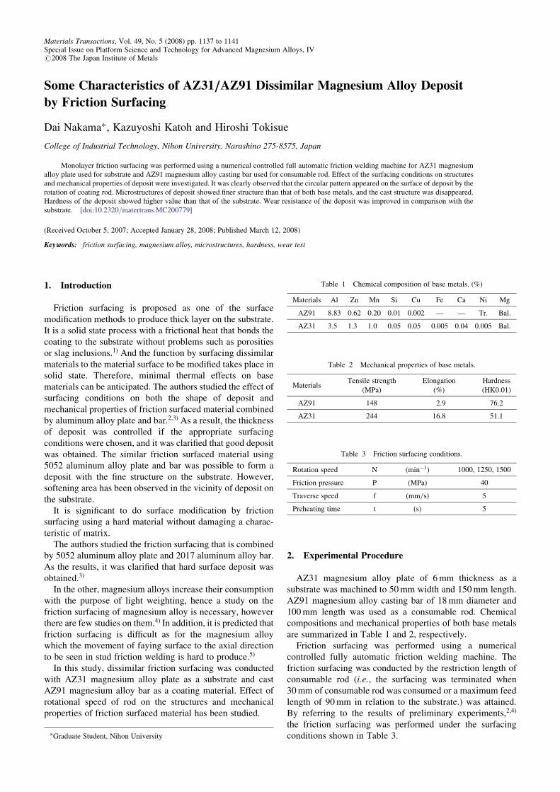
The effect of rotation speed of consumable rod on thethickness, width, and length of deposit are shown in Fig. 3.The thickness of deposit decreased with increasing rotationspeed of consumable rod. The width of deposit tended todecrease with an increase of the rotation speed. This might beattributed to that width of the deposit is decreased by adecrease in the closure area of substrate and consumable rod.For the identical reason for the decrease in the closure areaseen during friction with increasing rotational speed of
Table 4 Wear test conditions.
Friction load P0 (N) 20.6, 31.4, 61.8
Friction speed V (m/s) 1.97
Friction distance L0 (m) 200
Fig. 1 Measurement positions of temperature.
Fig. 2 Appearances of deposit.
1138 D. Nakama, K. Katoh and H. Tokisue
consumable rod which is exhibited during friction welding.6)
The ideal length of the deposit is 108mm that is calculatedfrom the feed distance and the diameter of the consumablerod. The effect of the rotational speed on the length of depositwas small, and the length reached almost 108mm under allconditions. These tendencies are similar to those observed inaluminum alloy deposit, however the thickness of deposit
was thinner and the width of deposit was narrower incomparison with the aluminum alloy deposit.
The surfacing efficiency was determined based on theassumption that the weight ratio of the consumable rod beforeand after surfacing is associated with the shape of deposit.The results of measurements of surfacing efficiency areshown in Fig. 4. The surfacing efficiency was loweredwith increasing rotational speed of the consumable rod. Thistendency is similar to that observed in the friction surfacingusing an aluminum alloy. The surfacing efficiency isremarkably small as 20%–60% of that of the aluminumalloy deposit.
It is considered that the difference of the surfacingefficiency of both materials was due to a difference of theductility that affected the movement of the faying surface.
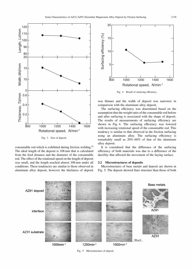
3.2 Microstructures of depositsMicrostructures of base metals and deposit are shown in
Fig. 5. The deposit showed finer structure than those of both
80
90
100
110
120
Leng
th, L
d /m
m
5
10
15
20
Wid
th,W
d /m
m
800 1000 1200 1400 16000
0.2
0.4
0.6
Thi
ckne
ss, T
d /m
m
Rotational speed, N /min-1
Fig. 3 Size of deposit.
800 1000 1200 1400 16000
5
10
15
20
Rotational speed, N /min-1
Sur
faci
ng e
ffici
ency
(%
)
Fig. 4 Result of surfacing efficiency.
Fig. 5 Microstructures of deposit.
Some Characteristics of AZ31/AZ91 Dissimilar Magnesium Alloy Deposit by Friction Surfacing 1139
base metals, in addition cast solidified structure observed inthe base metal of rod was not observed in the deposit.
The weld interface can be clearly distinguished betweenthe deposit and the substrate. Although observations of weldpenetration of coating material into a substrate have beenreported in surfacing by fusion welding.7) However, on thepresent friction surfacing, which is a solid-state surfacemodification technology, penetration of the coating materialinto the substrate was not observed. In addition, nomechanically mixed layer as represented for the case ofaluminum alloy3) was observed at the weld interface betweenthe deposit and the substrate.
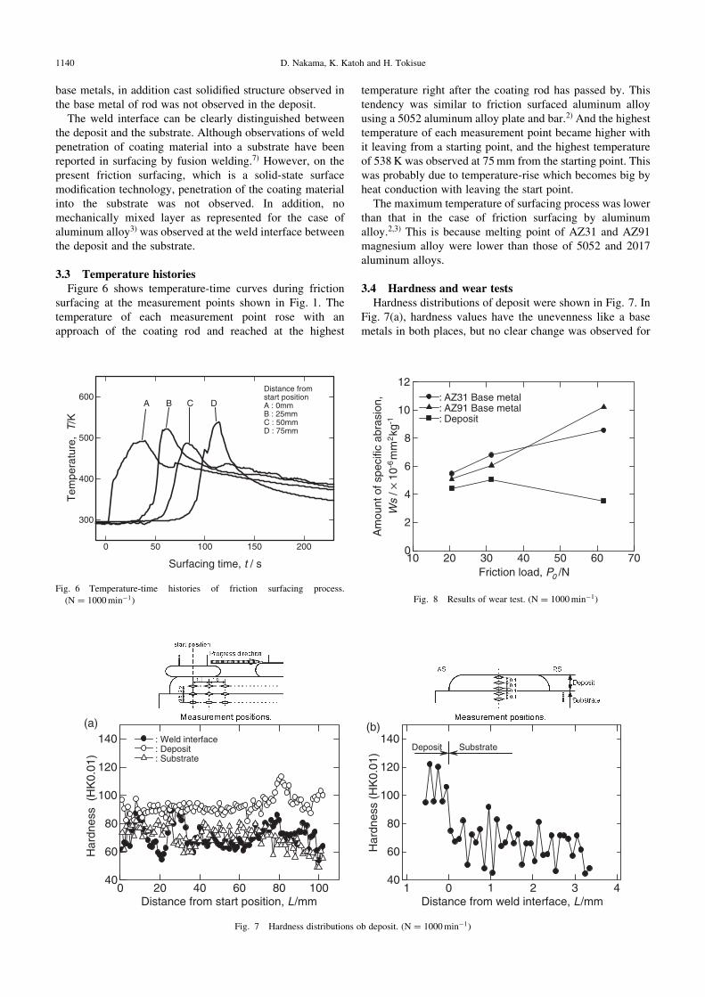
3.3 Temperature historiesFigure 6 shows temperature-time curves during friction
surfacing at the measurement points shown in Fig. 1. Thetemperature of each measurement point rose with anapproach of the coating rod and reached at the highest
temperature right after the coating rod has passed by. Thistendency was similar to friction surfaced aluminum alloyusing a 5052 aluminum alloy plate and bar.2) And the highesttemperature of each measurement point became higher withit leaving from a starting point, and the highest temperatureof 538K was observed at 75mm from the starting point. Thiswas probably due to temperature-rise which becomes big byheat conduction with leaving the start point.
The maximum temperature of surfacing process was lowerthan that in the case of friction surfacing by aluminumalloy.2,3) This is because melting point of AZ31 and AZ91magnesium alloy were lower than those of 5052 and 2017aluminum alloys.
3.4 Hardness and wear testsHardness distributions of deposit were shown in Fig. 7. In
Fig. 7(a), hardness values have the unevenness like a basemetals in both places, but no clear change was observed for
0 50 100 150 200
300
400
500
600
Surfacing time, t / s
Tem
pera
ture
, T
/K
Distance from start positionA : 0mmB : 25mmC : 50mmD : 75mm
A B C D
Fig. 6 Temperature-time histories of friction surfacing process.
(N ¼ 1000min�1)
0 20 40 60 80 10040
60
80
100
120
140
Har
dnes
s (
HK
0.01
)
Distance from start position, L /mm
: Weld interface : Deposit : Substrate
(a)
0140
60
80
100
120
140
Distance from weld interface, L /mm
Har
dnes
s (H
K0.
01)
Deposit Substrate
1
(b)
2 3 4
Fig. 7 Hardness distributions ob deposit. (N ¼ 1000min�1)
10 20 30 40 50 60 700
2
4
6
8
10
12A
mou
nt o
f spe
cific
abr
asio
n,
Friction load, P0 /N
: AZ31 Base metal: AZ91 Base metal: Deposit
-6m
m2kg
-1W
s / ×
10
Fig. 8 Results of wear test. (N ¼ 1000min�1)
1140 D. Nakama, K. Katoh and H. Tokisue

the hardness distribution. In Fig. 7(b), the hardness of depositwas higher than that of the substrate. Hardness change suchas softened area like an aluminum alloy deposit on substratecould not be recognized. Hardness of the deposit showedhigher value than that of the AZ91 magnesium alloy basemetal. The hardness distribution is similar to that of AZ31magnesium alloy friction welded to AZ91 magnesium alloycastings.5) Difference in hardness of the deposits wasconsidered to be cast structure of the AZ91 magnesiumalloy base metal which is consumable rod became the finestructure by friction surfacing.
Results of wear tests are shown in Fig. 8. Specific wear ofboth base metals tended to increase with increasing frictionload, and little difference of specific wear values between thematerials was obtained. Specific wear of the deposit showedlower value than those of both base metals. It was clear thatfriction surfacing improved the wear resistance. It isconsidered that the deposit became to have fine structureand hence of hardness.
Surfaces of wear tested specimen were shown in Fig. 9. Incase of a friction load of 6.3 kg, width of wear mark on bothbase metals were large, while the deposit showed smallerwidth and this value was the same as that of base metals at alow friction load.
4. Conclusions
Friction surfacing was conduced using AZ31 magnesiumalloy plate as a substrate and AZ91 magnesium alloy bar
using a coating rod. The influence of surfacing conditions onstructure and mechanical properties of the friction surfacedmaterial has been investigated. The following results wereobtained.1) The circular pattern due to the rotation of consumable
rod was clearly observed on the surface of deposit.2) The cast structure which was observed in AZ91 alloy
base metal was not observed in the deposit. Micro-structure of the deposit was finer than that of theconsumable rod and substrate.
3) The highest temperature during surfacing process was538K at 75mm position from the starting point.
4) Hardness of the deposit was higher than that of theAZ91 magnesium alloy base metal.
5) The deposit showed higher wear resistance than thoseof both base metals.
REFERENCES
1) E. D. Nicholas and W. M. Thomas: Weld. J. 65 (1986) 17–27.
2) H. Sakihama, H. Tokisue and K. Katoh: Mater. Trans. 44 (2003) 2688–
2694.
3) H. Tokisue, K. Katoh, T. Asahina and T. Ushiyama: Mater. Trans. 47
(2006) 874–882.
4) H. Sakihama, H. Tokisue and K. Katoh: Proc. of The 100th Conf. Jpn.
Inst. Light Met. (2001) 223–224.
5) K. Katoh, T. Asahina and H. Tokisue: J. Jpn. Inst. Light Met. 44 (1994)
562–566.
6) A. Hasui and S. Fukushima: J. Jpn. Weld. Soc. 44 (1975) 1005–1010.
7) Y. Kanbe et al.: Quart. J. Jpn. Weld. Soc. 11 (1993) 247–253.
Fig. 9 Appearances of wear tested specimen. (N ¼ 1000min�1)
Some Characteristics of AZ31/AZ91 Dissimilar Magnesium Alloy Deposit by Friction Surfacing 1141