from behavior to structure: high-level synthesis …fglima/projeto/paper1.pdf · from behavior to...
TRANSCRIPT

FROM BEHAVIOR TO STRUCTURE:
HIGH-LEVEL SYNTHESIS
R. CAMPOSANO IBM T J Watson Research Center
In this tutorial, the author describes how high-level synthesis bridges the
gap between behavioral specifications and hardware structure by automatically
generating a circuit description from a netlist. The resulting description can be used for other design automation tools
such as logic synthesis and layout. Describing high-level synthesis for synchronous digital hardware, the
author explains the steps of the process, which include compilation,
transformation, scheduling, and allocation.
igh-level synthesis bridges the gap between the high-level behavioral specification of a digital circuit and its structure. As opposed to logic synthesis, which optimizes only combina- H tional logic, high-level synthesis deals with memory elements,
the interconnection structure, such as buses and multiplexers, and the sequential aspects of a design.
The behavioral specification aims at describing only the functionality of a circuit, or what the circuit must do. The specification is usually in a sequential or procedural language similar to programming languages such as C or Pascal-for example, sequential VHDL. Circuit structure, on the other hand, gives strong hints about the circuit's implementation, or how it is built. The structure is described by a netlist, a list of components and their interconnections.
The first step in synthesis is to compile a specification into an internal representation. The second step is to apply high-level transformations with the goal of optimizing the behavior. Finally, scheduling and alloca- tion convert the behavior into a structure. Scheduling determines the time at which each operation is executed, while allocation synthesizes the necessary hardware to perform the operations. The structure is then passed to other design tools for logic synthesis.
The advantage of high-level synthesis is that behavioral specifications are generally shorter than lower level structural specifications. Thus, they are easier to write, understand, and change. This makes them less error prone and faster to simulate, which makes the design of complex systems easier and allows a considerably shorter design cycle. But, as is often the case, automation at this level also exacts a price, and we may have to trade advantages for larger or slower hardware. Moreover, design automation cannot generally match the abilities of a skilled human designer. Despite these drawbacks, design automation does increase productivity significantly.
8
~
DESIGN REPRESENTATION A requisite for high-level synthesis is the precise definition of circuit
behavior and structure and the systematic classification of design representations. As Table 1 shows, this definition and classification commonly involves two orthogonal axes: the domain and the level. There are three domains: the behavioral, the structural, and the physical. Ideally, pure behavior is described in terms of an input-output relation- ship, such as a set of Boolean equations for a combinational network. The structure describes the topology of a system and is typically given
0740-7475/90/0010 0861 OW1990 IEEE IEEE DESIGN & TEST OF COMPUTERS
~~
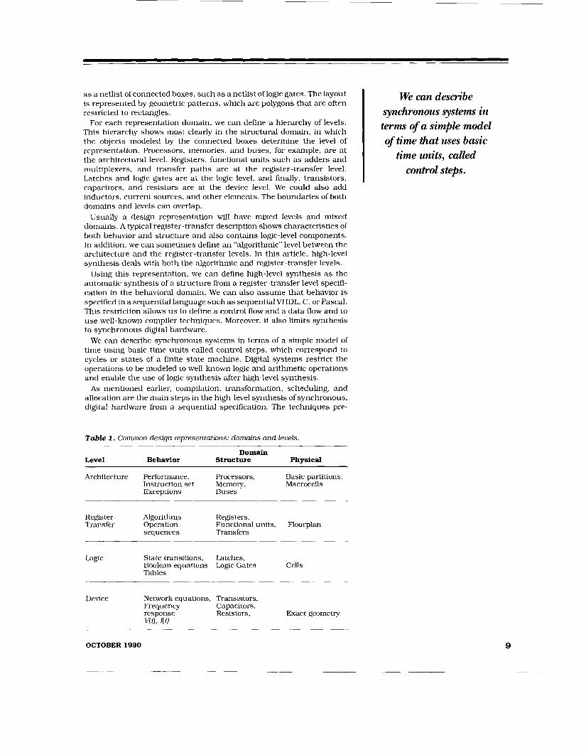
as a netlist of connected boxes, such as a netlist of logic gates. The layout is represented by geometric patterns, which are polygons that are often restricted to rectangles.
For each representation domain, we can define a hierarchy of levels. This hierarchy shows most clearly in the structural domain, in which the objects modeled by the connected boxes determine the level of representation. Processors, memories, and buses, for example, are a t the architectural level. Registers, functional units such as adders and multiplexers, and transfer paths are at the register-transfer level. Latches and logic gates are a t the logic level, and finally, transistors, capacitors, and resistors are at the device level. We could also add inductors, current sources, and other elements. The boundaries of both domains and levels can overlap.
Usually a design representation will have mixed levels and mixed domains. A typical register-transfer description shows characteristics of both behavior and structure and also contains logic-level components. In addition, we can sometimes define an “algorithmic” level between the architecture and the register-transfer levels. In this article, high-level synthesis deals with both the algorithmic and register-transfer levels.
Using this representation, we can define high-level synthesis as the automatic synthesis of a structure from a register-transfer level specifi- cation in the behavioral domain. We can also assume that behavior is specified in a sequential language such as sequentialVHDL, C , or Pascal. This restriction allows u s to define a control flow and a data flow and to use well-known compiler techniques. Moreover, it also limits synthesis to synchronous digital hardware.
We can describe synchronous systems in terms of a simple model of time using basic time units called control steps, which correspond to cycles or states of a finite state machine. Digital systems restrict the operations to be modeled to well-known logic and arithmetic operations and enable the use of logic synthesis after high-level synthesis.
As mentioned earlier, compilation, transformation, scheduling, and allocation are the main steps in the high-level synthesis of synchronous, digital hardware from a sequential specification. The techniques pre-
Table 1. Common design representations: domains and levels.
Level Behavior Structure Physical
_ _ _ _ _ ~ . ~
Domain
Architecture Performance, Processors, Basic partitions, Instruction set Memory, Macrocells Exceptions Buses
Register - Algorithms Registers , Transfer Operation Functional units, Floorplan
sequences Transfers
Logic State transitions, Latches, Boolean equations Logic Gates Cells Tables
Device Network equations, Transistors, Frequency Capacitors, response Resistors, Exact geometry Vt), I(t)
We can describe synchronous systems in terms of a simple model of time that uses basic
time units, called I control steps.
OCTOBER 1990
__ __

HIGH-LEVEL SYNTHESIS
Compilation in high-level synthesis
is almost identical to the nonoptimizing
compilation of fw-ogramming
langmges.
function Even (Inp: three-bit-vector) return bit is variable Par: bit; begin
Par := 1 ; for I in 1 to 3 loop
if Inp(l) = 1 then Par := not Par; end if;
end loop; return Par;
end Even:
Figure 1 . A three-bit even parity generator in W D L .
sented in this article are for general-purpose synthesis and do not include special-purpose synthesis for applications such as digital signal processing or for specialized architectures. The examples are simple, ignoring issues such as hierarchy, concurrent processes, multifunction designs, and parallelism extraction. Most of the work in the literature addresses these topics in some form.
COMPILATION Figure 1 shows the description of a three-bit, even-parity generator in
sequential VHDL. The function Even returns a 1 if it encounters an even number of 1’s in the three-bit input vector Inp. Parity generators are well-known, and 1 am not suggesting that they should be specified behaviorally and synthesized. However, this example illustrates that such a task can be done, and synthesis will yield the expected results.
Compilation in high-level synthesis is almost identical to the non- optimizing compilation of programming languages. In this case, compi- lation is basically a one-to-one transformation of the initial specification into a new internal representation of the behavior, better suited to synthesis. Optimization is a separate issue because optimization in hardware synthesis differs from the optimization of compilers. Graphs are used most often for internal representation.
Figure 2 gives data-flow and control-flow graphs for the example in Figure 1. The data-flow graph is a directed graph that indicates how the information flows. Its nodes are operations, designated by circles, and variables. Variables can be constants such as 1 or arrays such as Inp. “Control” represents variables that have to be passed to the control. For example, the result of the test I > 3 is passed to the control, which must decide which of two conditional branches to take. Arrows represent edges that link operation nodes to variable nodes and vice versa. An operation can either use or write the value in a variable. Filled arrows represent bit selection, which is Inp(4 in the example. The data-flow graph can be disconnected. The sample graph has three parts:
1. the test (= 1) of the bits of Inp
2. initialization (:=), incrementing (+l), and test (>) of I
3. initialization (:=I and negation (z) of Par.
These natural partitions of the data-flow graph may help later in partitioning the design for logic synthesis and layout.
The control-flow graph is also directed and indicates the sequence of operations-how the operations in the data-flow graph have to be controlled to perform the specified behavior. Arrows link an operation to its immediate successors. Filled arrowheads represent conditional branching, depending on the results of a test. Each arrow has the condition of each branch attached to it, either true or false. The control-flow graph for sequential programs without dead code is always connected. Moreover, there is a first operation (marked entry) from which all other operations can be reached.
Operations in the data-flow and control-flow graphs correspond to and are labeled with the operation they represent. For clarity, the control- flow graph label includes operands. Some representations choose to represent the operations only once, mixing both graphs. Also, some representations preserve only the essential parts of the control flow, such as loops and conditional branches. In the example, the ordering of
10 IEEE DESIGN & TEST OF COMF’UTERS
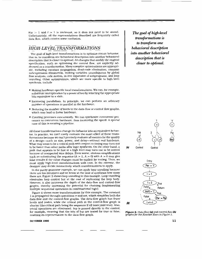
Par := 1 and I := 1 is irrelevant, so it does not need to be stored. Unfortunately, all the representations described are frequently called data flow, which creates some confusion.
HIGH- LE VEL TRANSFORMATIONS The goal of high-level transformations is to optimize circuit behavior,
that is, to transform one behavioral description into another behavioral description that is closer to optimal. All changes that modify the original specification, such as optimizing the control flow, are explicitly ad- dressed as a transformation. Many compiler optimizations are appropri- ate, including constant propagation, dead-code elimination, common subexpression elimination, making variables unambiguous by global flow analysis, code motion, in-line expansion of subprograms, and loop unrolling. Other optimizations, which are more specific to high-level synthesis, include
Making hardware-specific local transformations. We can, for example, substitute multiplication by a power of two by selecting the appropriate bits equivalent to a shift.
Increasing parallelism. In principle, we can perform an arbitrary number of operations in parallel in the hardware.
Reducing the number of levels in the data-flow or control-flow graphs, which may lead to faster hardware.
Creating processes concurrently. We can synthesize concurrent pro- cesses as concurrent hardware, thus increasing the speed. A special case of this is creating a pipeline.
All these transformations change the behavior into an equivalent behav- ior. In practice, we can't easily evaluate the exact effect of these trans- formations because we can't precisely evaluate all metrics for the quality of a design-such as size, power, and delay-without real hardware. What may seem to be a critical path with respect to timing may turn out to be faster than other paths after logic synthesis. On the other hand, a path that appears to be fast at a high level may turn out to be critical because of unexpected wire delays. Even worse, obvious simplifications such as substituting the sequence [A := 1, A := 0) with A := 0 may give false results if the value changes must be explicit for testing. Thus, we must apply high-level transformations with care. In the extreme, the designer may decide interactively which transformations to apply.
In the parity generator example, we can apply loop unrolling because there are few iterations and we know at the time of synthesis how many there are. Figure 3 shows loop unrolling in this example. Loop unrolling eliminates loop control but at the cost of replicating the loop body. However, it also increases the depth of the data-flow and control-flow graphs, thereby increasing the potential for chaining [implementing multiple sequential operations in combinational logic).
Figure 4 shows more transformations for this example. The constant 1 is propagated through operations := and not, which simplifies both the data-flow and the control-flow graphs. The data-flow graph has fewer levels and nodes, while the critical path in the control-flow graph is shorter (the critical path being the sequence if all tests yield true). Also, trivial operations are eliminated. Inp is passed directly to the control, for example, meaning that the bits of Inp are tested for true or false, omitting its representation in the data-flow graph.
OCTOBER 1990
The goal of highZeue1 tran.formatim is to Eransforrn one
behavioral desm3tion into another behavioral
description that is ~
I closer to optimal.
1
9 i i
(4 Control Control
Entry
I :=1
Return Inp(l) = '1'
Figure 2. Data-@w (4 and control-Jow &) graphs for thefunction Even in Figure 1 .
11

HIGH-LEVEL SYNTHESIS
It's not easy to evaluate the exuct efsect of
tram$wmations, since we can't precisely
evaluate metria such as size, power, and delay without real
hardware.
12
& (Bg (-j$
Par
False lnp(2) = '1'
/ \ True False
/ \ True False
Figure 3. Loop unrolling.
Entry I Q
'1' '0'
Par
Figure 4. Constant propagation and the elimination of trivial operations.
SCHEDULING AND ALLOCATION Behavior is converted into a structure in two main steps: scheduling
and allocation. We can evaluate the result only after applying both steps. Basically, scheduling assigns each operation to a point in time, while allocation assigns each operation, variable, and communication path to a piece of hardware. The two are highly interdependent and techniques disagree as to which should come first. Most approaches do scheduling first and rely on estimates of the required hardware. Other approaches allocate the data-path first, subject to given constraints, and then schedule, taking into account the already given hardware. We can also intertwine scheduling and allocation in an attempt to optimize a cost function that includes both the number of control steps and the hardware.
IEEE DESIGN & TEST OF COMPUTERS

SCHEDULING The goal of scheduling is to optimize the number of control steps
needed to complete a function, given certain limits on hardware re- sources and cycle time. A scheduling algorithm must take into account control constructs such as loops and conditional branching and data dependencies expressed in the data-flow graph. The result of scheduling is that each operation is scheduled into one or more control steps.
The control-flow graphs in Figures 2 and 4 give a trivial schedule, in which operations are executed one at a time. At the other extreme, if there are no loops, no limits on hardware resources, and no explicit constraints such as permissible delays, we could schedule all operations in one control step. We can schedule the behavior of the parity generator in Figure 4, for example, in just one control step, resulting in purely combinational logic. This strategy is probably the most desirable for a parity generator. Scheduling in this case requires implementing multiple sequential operations in combinational logic. This chaining usually decreases the number of control steps but increases the depth of combinational logic, possibly making the control steps-and thus the cycle time-longer.
Alternatively, we could schedule operations in three consecutive con- trol steps, as Figure 5 illustrates. The result would be available in the fourth control step. A scheduling algorithm that allows only one sequen- tial operation per control step would produce such as schedule. The result is a short cycle time. The sequential schedule is quite similar to the initial sequence (before loop unrolling) suggested by the control-flow graph in Figure 2. The difference is that we do not have to initialize PAR in the schedule in Figure 5 because of constant propagation.
Figure 5 shows only the data-flow graph. We also need to know which branch to take in each control step. In control step 3, for example, PAR is either negated or left unchanged, depending on the value of Inp(3). We can assume that the result stored in PAR is available at the beginning of the next control step. Hence, the final result will be available in the fourth control step.
Scheduling assumes certain hardware constraints. In synchronous hardware, the basic constraints are that every unit of hardware can be used only once during a control step. Registers can be loaded only once, combinational logic may evaluate only once (feedback is forbidden) and buses may carry only one value. If we have constraints on the hardware, such as size, delay, and power, an optimal schedule is one with the minimum number of control steps to complete a function within those constraints. Unfortunately, we can only estimate size, delay, and power at this level.
Many scheduling algorithms for high-level synthesis are in use. Among the simpler ones are as-soon-as-possible, or ASAP, and as-late-as-pos- sible, or ALAP. Both of these consist basically of sorting the data-flow graph topologically according to its data dependencies using a depth- first (-last) search. For the example, if there is enough hardware to execute two operations in one control step, ASAP scheduling would give the schedule in Figure 5. The operations in step 1 have no data dependencies, so they are scheduled first, the operations in step 2 depend on PAR, so they are sorted after the operations in step 1 which write PAR, etc.
Another type of scheduling is called list scheduling. Here, we create a list that gives the order in which the operations are scheduled. In addition to the topological order, a criterion such as the length of the longest path to the end (completion of the function) is used to order the list. Thus, data dependencies permitting, operations on longer paths are
OCTOBER 1990
The goal of scheduling is to optimize the number of control
steps needed to complete afinction, given certain limits
on hardware resources and cycle time.
'1' '0' Step
Par
&@ 2
Par
Par 4
Figure 5. Scheduling in three control steps.

HIGH-LEVEL SYNTHESIS
Many scheduling algorithms for high-level
synthesis are in use. Among the simpler ones are as-soonzrs+ossible and asZatea+ossi ble.
scheduled earlier than operations on shorter paths, since longer paths require more control steps. Another criterion used is the operation’s mobility, which is the difference between the ASAP and ALAF’ schedules. Operations with lower mobilities, which can be scheduled in fewer control steps, are scheduled earlier. In the example, all paths have the same length (three operations), and the ASAP and ALAP schedules are the same, so list scheduling would also result in the schedule in Figure 5.
Force-directed scheduling uses a global criterion that indicates how crowded a control step is compared with others to decide where to schedule an operation. We can calculate the probabilities of operations being in a given control step by using mobility. For example, if we can
TERMS IN HIGH-LEVEL SYNTHESIS Chaining. The scheduling of operations that have data dependen- cies in the same control step-data dependency meaning that one uses the output of the other. Chaining can reduce the number of control steps, since we can schedule more operations in the same step. It may also increase the cycle time, however, because the delay of executing chained operations can be significant. Control. The part of the design that deals with control functions. Typical control units are finite state machines (sometimes called hard-wired control) and microprogrammed controllers. Controllers that are finite state machines are characterized by random logic with little structure. Control step. The basic unit of time used in scheduling. A control step is equal to a state in designs that use a finite-state-machine controller. It is equal to a microprogram step in microprogrammed control units. Data path. Part of the design that deals with the computation of data. Data paths are often characterized by regular logic and bit slices-for example, &Us or adders. The boundary between the data path and the control is not defined precisely. To understand the difference between the two, take the comparison a = 3, which can be done in either the control or the data path. If it is done in the control, a is passed from the data path to the control. If it is done in the data path, the resulting bit of a = 3 is passed from the data path to the control. Loop unrolling. The replication of the loop body. Loops with known boundaries can be completely unrolled. Loops with condi- tional boundaries, such as While and Until loops, can be partially unrolled. Loop unrolling permits more freedom in scheduling and allocation and allows optimization across loop boundaries. Sequential language. Also called procedural or imperative lan- guage, a language in which statements are executed sequentially in the given order, and variables retain their values until a new value is assigned to them. Sequential languages permit multiple assign- ments to a variable, as opposed to functional or declarative lan- guages, which permit only single assignment and execute state- ments (functions) concurrently. Variable and state encoding. The assignment of a given code to the symbolic values of a variable or state. In the synthesis of finite state machines, for example, we could encode two symbolic states, so and S I , as binary vectors 00 and 10. VHDL. Short for VHSIC (very high speed IC) hardware description language. VHDL is IEEE standard 1076-1987. It can describe hard- ware at various levels, and sequential VHDL, in particular, is a pos- sible input language for high-level synthesis.
14 IEEE DESrGN & TEST OF COMPUTERS
schedule an operation in three possible steps, it has a mobility of 3. Thus, the probability in each of these steps is 1/3. Adding all the probabilities over one control step, s, gives a measure of how crowded this control step is. This measure is called the distribution because it tells how many operations will probably be executed in s and hence, how much hardware will be required.
After calculating the distribution for all control steps, we can calculate the effect for each possible assignment of an operation, U , to s. Then we can schedule the operation/control-step pair that minimizes the distri- bution differences among control steps. We calculate the quantitative measure of scheduling, U , in s on the distribution using an equation that is analog to the force in a spring (spring constant times displacement, where the constant is the original distribution for a control step and the displacement is the change in the distribution value). Thus, this sched- uling algorithm is called force-directed scheduling.
Another technique for scheduling operations is control-step merging. In this approach, we first assign each operation to a separate control step and then merge control steps iteratively without violating any constraints. We can also move operations among control steps. The opposite of merging is control-step splitting. Here, we first assign all operations to a single control step and then divide this control step until we have no constraint violations.
All these algorithms for scheduling are heuristics. Although optimal scheduling is NP-complete, heuristics yield reasonably good results.
ALLOCATION The goal of allocation is to optimize the amount of hardware needed,
given a certain schedule. Allocation naturally falls into three parts: functional-unit allocation, register allocation, and bus allocation. In high-level synthesis, the main aim of allocation is to share hardware units, for example to decide which variables can be mapped onto a common register. Since the goal is to optimize the overall hardware, we would like to do all three kinds of allocation simultaneously.
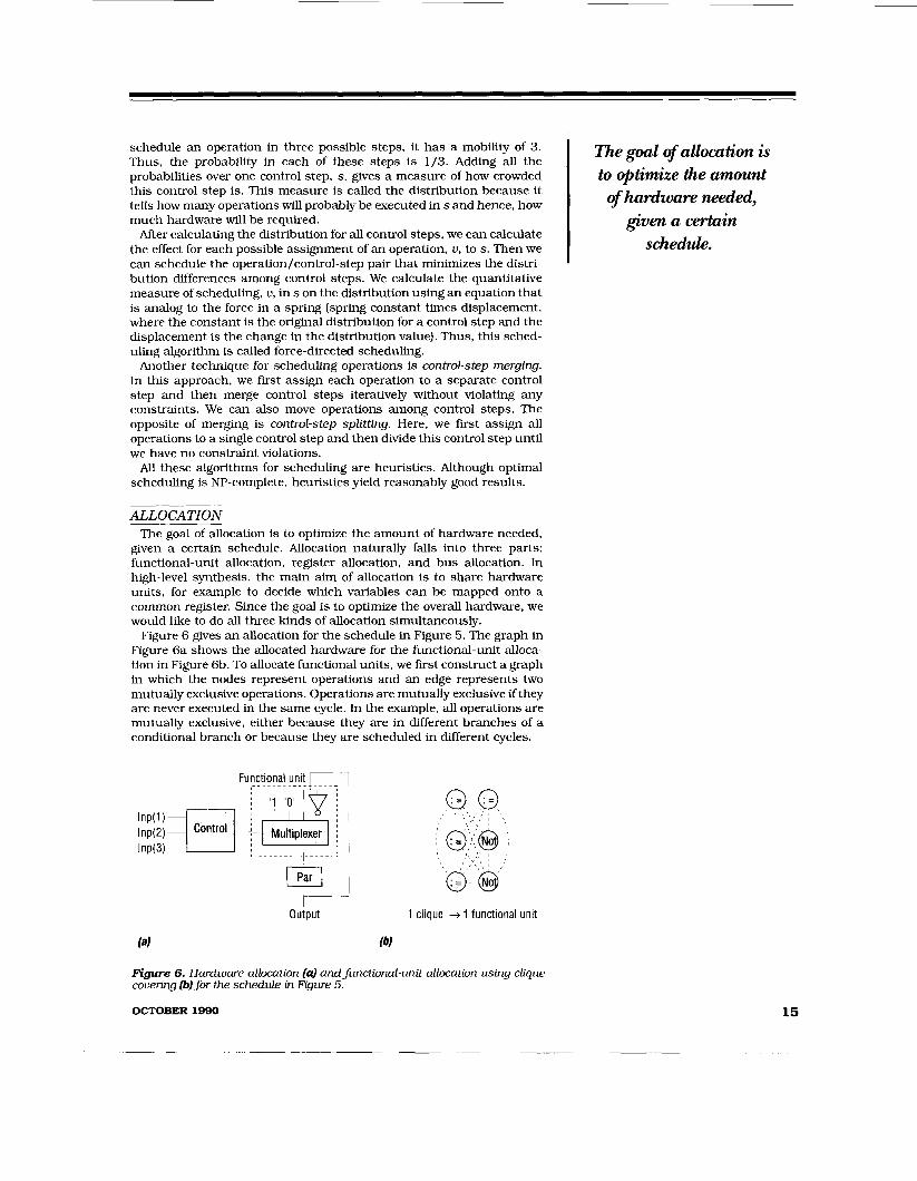
Figure 6 gives an allocation for the schedule in Figure 5. The graph in Figure 6a shows the allocated hardware for the functional-unit alloca- tion in Figure 6b. To allocate functional units, we first construct a graph in which the nodes represent operations and an edge represents two mutually exclusive operations. Operations are mutually exclusive ifthey are never executed in the same cycle. In the example, all operations are mutually exclusive, either because they are in different branches of a conditional branch or because they are scheduled in different cycles.
Functional unit 1-1 __......___ .....
I _ - _. . . . _._I_ -. .. -,
output 1 clique -+ 1 functional unit
Figure 6. Hardware allocation (a) andfunctiondunit allocation using cliqw covering (b) for the schedule in Figure 5.
OCTOBER 1990
The goal of allocation is to optimize the amount of hardware needed,
given a certain schedule.
15

HIGH-LEVEL SYNTHESIS
A clique is a fully connected subgraph, in
which all Operations can share the same
hardware.
When all operations within a subgraph are mutually exclusive, the subgraph is fully connected. In this type of subgraph, called a clique, all operations can share the same hardware. If the graph is covered by a minimum number of these cliques-called a minimal clique couerinp- the minimum amount of hardware will be required (one unit per clique). In the example, there is just one clique, which means that one functional unit has to perform the functions :=O, := l , :=, and not (output:=O, output:=l, output:=input and output:=not input).
Figure 6 also gives a possible implementation of the functional unit, in which a multiplexer selects the required result. We can simplify this implementation later on by using logic synthesis. Registers and buses are allocated as a final step in allocation. In the figure, only Par has to be passed among control steps, so one register is sufficient. The com- munication structure is trivial: two buses connect the register to the functional unit.
Besides the data-path just described, we have to allocate a control part. At this point control is already totally specified. Scheduling determined the control steps, while data-path allocation determined the required output-which function the functional unit is to perform in each control step. We can implement control for one sequential design using one finite state machine, which we can synthesize using standard techniques based on state assignment, variable encoding, and logic synthesis.
Table 2 gives the control specification for the allocation in Figure 6. Note that the given finite state machine will loop, computing a result every three cycles. The result will be available during the first cycle, called State 1. Each of the three input bits must be stable during one of three consecutive cycles. This specification actually represents a simple interface protocol. Without timing constraints, this design is valid. In practice, however, we are likely to have a specification of the interface’s timing behavior and would probably have to latch inputs and/or out- puts, which could constrain scheduling.
This hardware implementation is, of course, a rather clumsy sequen- tial implementation of the calculation of a parity bit because of the schedule chosen. If we had instead scheduled the complete graph in Figure 4 into one cycle, we would have had the familiar implementation in combinational logic. Figure 7 shows the hardware and functional-unit allocation using the schedule in Figure 4. It requires three functional units. We can simplify the design in Figure 7 using logic synthesis, which will yield the familiar XOR parity generator.
Besides using this clique-covering method, which we can easily refor- mulate as a graph-coloring problem, we can approach allocation as a
Table 2. Control specijlcatwn for Fgure 6.
State Inp(1) Inp(2) Inp(3) Next State Function
State 1 o x X State 1 1 X X
State 2 :=1 State 2 :=0
State 2 x o x State 2 x 1 X
.- State 3 .- State 3 not
.- State 3 x X 0 State 1 .- State 3 x X 1 State 1 not
IEEE DESIGN & TEST OF COMPUTERS

3 cliques + 3 functional units
Figure 7. Hardware allocation and functional-unit allocation for a schedule with one control step (combinational logic).
0-1 linear-programming problem. Also, many researchers use greedy heuristics. These algorithms select an operation and map it to already existing hardware if possible, or allocate new hardware. The selection criteria-the criteria used to determine what operation is allocated-can be size or the impact on the already allocated hardware. Other research- ers have used expert systems for allocation, attempting to capture the knowledge of a particular design problem, such as microprocessor design, in a rule base.
One obstacle of automatic allocation is that the process is NP-complete. Also, evaluating allocation results is more difficult than evaluating scheduling results. The ultimate evaluation criterion for allocation is the design by an expert, who may use tricks that an automated system is not likely to emulate.
PROBLEMS As mentioned earlier, we can use the results of high-level synthesis as
input for logic synthesis, which optimizes the combinational logic. We can then present these results for layout synthesis, which designs the chip geometry. These synthesis steps are fairly independent, which poses a problem when we try to flow information among them. For example, detailed design constraints are not easily passed from high- level synthesis to logic synthesis. Conversely, lower level implementation information such as sue, delay, and power is often not passed to high-level synthesis.
In designing an interface for these two levels, we must consider structural issues such as regularity of the design, particularly of the data path: the level of the primitives passed: and the influence of the size and functionality of the combinational logic partitions. Nonstructu- ral interface information, such as the underlying control scheme, con- straints on time and power. the required testability, and the required technology libraries, should also be passed or considered implicitly in high-level synthesis.
The gap between high-level and logic synthesis is starting to be bridged, however. The synthesis of finite state machines, which involves state encoding and the encoding of symbolic variables in logic synthesis, is a sign of progress in this area. But there are several obstacles. One of the most important issues is concurrency. Besides concurrency at the
OCTOBER 1990
The ultimate evaluation m''tem'0n for allocation
expert, who may use tricks that an
~ automated system is 1 not likely to emulate.
l is the design by an
I
17

HIGH-LEVEL SYNTHESIS
HIGH-LEVEL SYNTHESIS: NOT A NEW TECHNOLOGY
-
We can trace the roots of high-level synthesis back to the 1960s when design automation was also in its infancy. The Alert system developed at the IBM T.J. Watson Research Center was already addressing many problems in this area.’ During the 1970’s, design auto- mation development exploded, but the main practical problems to be solved were at lower levels, such as layout. Thus, high-level synthesis was considered an academic exercise, and research was restricted mainly to universities.
Carnegie-Mellon University has been the most prolific producer of high-level synthesis tools since 1973.2 In Europe, one of the first efforts was Mimola from the University of Kiel, which started as early as 1976.3 The Caddy/DSL system from the Universi of Karlsruhe has been under development since 1979. !iy
In the last decade, work on high-level synthesis has proliferated extensively within the academic community and has started to spread to industry. Carnegie-Mellon University has several r o ’ e c t ~ ~ . ~ as do the University of Southern california.7J’ d e University of California at
Karlsruhe University,” and Stanford Univer- sity.”In industry, AT&T Bell LaboratoriesI2 and IBM T.J. Watson Research CenterI3 have ongo;ysgrojects. There are also several interesting tutorials.
The design representation described in this article is taken from the Yorktown Intermediate Format (YIF]13 and the representation given in another work.17 Other well-known design representations are Value Trace ’* and DDS.7 Flamellg is a high-level synthesis approach based on transformations. The as-soon-as-possible scheduling algorithm and the list scheduling algorithm are in Davis et Parker et al.’ describe the critical- path-first algorithm, while Paulin and Knight2’ describe force-directed scheduling. There are also descriptions of control-step merging” and a more sophisticated version of control-step merging called percolation scheduling,22 and control-step ~plitting.’~
Tseng and Siework5 formulate allocation as a clique partitioning problem, while Hafer and Parker formulate it as a linear-programing problem.24 Kowalski uses an artificial intelligence approach to a l l ~ c a t i o n . ~ ~
REFERENCES 1. T. Friedman and S. Yang. “Methods Used in an Automatic
Logic Design Generator (ALERT),” IEEE Trans. Computers, Vol. C-18, NO. 7, July 1969, pp. 593-614.
2. M. Barbacci, Automatic EKploration of the Design Space for Register Transfer (RT) Systems, PhD dissertation, Dept. of CS, Carnegie-Mellon Univ., Cambridge, Mass., Nov. 1973.
3. G. Zimmermann, “Eine Methode zum Entwurf von Digitalrechnem mit der Programmiersprache MIMOLA,” Informatik-Fachberichte, Vol. 5, Springer-Verlag, Berlin, 1976 (in German).
4. R. Camposano and W. Rosenstiel. Algorithmische Synthese deterministischer (Petri-) Netze aus Ablaujbeschreibungen digitaler Systerne, Fakultat fur Informatik. University of Karlsruhe, Bericht 22/80, 1980.
5. C. Tseng and D. Siewiorek, “Automated Synthesis of Data Paths in Digital Systems,” IEEE Trans. Computer-Aided Design. Vol. CAD-5, No. 3, July 1986, pp. 379-395.
6. D. Thomas et al., ‘The Systems Architect‘s Workbench,” Roc. Design Automation Conf., June 1988. pp. 337-343.
7. D. Knapp and A. Parker, “A Unified Representation for Design Information,” F’roc. Symp. Computer Hardware De- scription Languages and Their Applications, Aug. 1985, pp. 337-353.
8. A. Parker, J . Pizarro and M. Mlinar, “MAHA: A Program for Datapath Synthesis,” Proc. Design Automation Conf., June 1986, pp. 461-466.
9. B. Pangrle and D. Gajski, “Design Tools for Intelligent Silicon Compilation,” IEEE Trans. Computer-Aided Design, Vol. CAD-6, NO. 6, NOV. 1987, pp. 1098-1 112.
10. R. Camposano and W. Rosenstiel, “Synthesizing Circuits from Behavioral Descriptions,” IEEE Trans. Computer- Aided Design, Vol. 8, No. 2, Feb. 1989. pp. 171-180.
11. D. Ku and G . De Micheli, “High-Level Synthesis and Opti- mization Strategies in Hercules and Hebe,” Proc. Conf. Logic and Architecture Synthesis, May 1990, pp. 9-14.
12. M. McFarland, “Using Bottom-Up DesignTechniques in the Synthesis of Digital Hardware from Abstract Behavioral Descriptions,” Roc. Design Automation Conf., June 1986,
13. R. Camposano, “Structural Synthesis in the Yorktown Silicon Compiler.” in VLSl 87: V L S I Design ofDigital Sys- tems, C. Sequin, ed., NorthHolland, Vancouver, 1988, pp. 61-72.
pp. 474-480.
14. M. McFarland, A. Parker, and R. Camposano, ‘Tutorial on High Level Synthesis,” Proc. Design Automation Conf., June 1988. pp. 330-336.
15. D. Thomas, “Automatic Data Path Synthesis,” in Advances in CAD for VLSI: Vol. 6, Design Methodologies, S. Goto, ed.. NorthHolland, Amsterdam. 1986, pp. 401-439.
16. R. Camposano, “Synthesis Techniques for Digital Systems Design,” Roc. Design Automation Conf., June 1985, pp. 475-480.
17. R. Camposano and R. Tabet, “Design Representation for the Synthesis of Behavioral VHDL Models,” Roc. Symp. Computer Hardware Description Languages and “heir Ap- plications, 1989.
18. M. McFarland, 7he Value Trace: A Data BaseforAutomated Digital Design, tech. rpt. DRC-01-4-80, Design Research Ctr., Camegie-Mellon Univ., Dec. 1978.
19. H. Trickey. “Flamel: A High-Level Hardware Compiler,” IEEE Trans. Computer-Aided Design, Vol. CAD-6, No. 2, Mar. 1987, pp. 259-269.
20. S. Davidson et al., “Some Experiments in Local Microcode Compaction for Horizontal Machines,” IEEE Trans. Comput- ers, Vol. (2-30, No. 7, July 1981, pp. 460-477.
21. P. Paulin and J. Knight, “Force-Directed Scheduling in Automatic Data Path Synthesis,” Roc. Design Automation Conf.. June 1987, pp. 195-202.
22. V. Berstis, ‘The V Compiler: Automatic Hardware Design.” IEEE Design & Test of Computers, Vol. 6 , No. 4, Apr. 1989, pp. 8-17,
23. R. Camposano, “Behavior-Preserving Transformations for High-Level Synthesis.” Roc. Workshop on Hardware Spec- fwation, Veriication, and Synthesis: Mathematical Aspects, Springer Verlag. Berlin, 1989.
24. L. Hafer and A. Parker, “Register-Transfer Level Design Automation: The Allocation Process,” Proc. Design Automa- tion Conf., June 1978, pp. 213-219.
25. T. Kowalski. An ArtGCid Intelligence Approach to VLSI Design. Kluwer Academic Pub., Boston, 1985.
18 IEEE DESIGN 81 TEST OF COMPUTERS
operational level, which scheduling handles adequately, we must be concerned with concurrency at the system level-for example, the automatic synthesis of pipelines.
System-level synthesis above the level described here is still an open research topic. Synthesis with constraints such as delay, area, and power and synthesis with interfaces-for example, a bus requiring a given protocol-are specialized topics that have received little attention. Despite the large amount of work and despite standardization efforts, languages are still considered an issue. One unanswered question is whether a sequential or a functional style description is better suited for behavioral specification and synthesis. The formal foundation of high- level synthesis is also still in its infancy. No coherent theory exists and there is no practical way of proving the equivalence of a behavioral and a structural description at the level addressed here. Current develop- ments in formal verification may help in this area.
We also need more work on design process issues. In addition to information flow from high-level synthesis to logic synthesis, we need the feedback of information from logic synthesis to high-level synthesis to improve the traditional top-down or meet-in-the-middle design in just one pass. A strict top-down approach makes it rather difficult to meet stringent design constraints and to evaluate designs at a high level because we must estimate information such as size and delay. Design iteration in a closed loop may help, but we must have much tighter system integration.
H igh-level synthesis is fairly well understood, and efficient algorithms exist for each step involved. The results of synthe- sis work so far indicate that we can synthesize problems of realistic size, although the designs are larger and slower than
the designs produced by human designers. Digital-signal processing is one area in which high-level synthesis is already in practice. Other areas have yet to see widespread practical application of this technology. Despite several open questions, however, the body of knowledge in high-level synthesis has reached a state in which practical applications in many areas certainly seem possible. @+
Despite several Open questions, the body of
knowledge in highZeve1 synthesis has reached a state in which practical
applications in many areas certainly seem
possible.
Center, where his interests include CAD and design automation for digital systems. Previously, he was assistant professor at the University of Siegen in Germany and was professor of computer science at the Universidad del Norte in Antofagasta in Chile. He was also a researcher in the Computer Science Research Laboratory of the University of Karlsruhe in Germany. He holds a diploma in electrical engineering from the University of Chile and a PhD in computer science from the University of Karlsruhe. His address is IBM T.J. Watson Research Center, PO Box 218, Yorktown Heights, NY 10598.
OCTOBER 1990 19