from conceptual design to performance optimization of etl ... · from conceptual design to...
TRANSCRIPT

The VLDB Journal (2017) 26:777–801DOI 10.1007/s00778-017-0477-2
REGULAR PAPER
From conceptual design to performance optimization of ETLworkflows: current state of research and open problems
Syed Muhammad Fawad Ali1 · Robert Wrembel1
Received: 11 December 2016 / Revised: 14 June 2017 / Accepted: 9 August 2017 / Published online: 6 September 2017© The Author(s) 2017. This article is an open access publication
Abstract In this paper, we discuss the state of the art andcurrent trends in designing and optimizing ETL workflows.We explain the existing techniques for: (1) constructing aconceptual and a logical model of an ETL workflow, (2)its corresponding physical implementation, and (3) its opti-mization, illustrated by examples. The discussed techniquesare analyzed w.r.t. their advantages, disadvantages, and chal-lenges in the context ofmetrics such as autonomous behavior,support for quality metrics, and support for ETL activi-ties as user-defined functions. We draw conclusions on stillopen research and technological issues in the field of ETL.Finally, we propose a theoretical ETL framework for ETLoptimization.
Keywords ETL workflow · ETL conceptual design ·ETL logical design · ETL physical implementation · ETLoptimization
1 Introduction
A data warehouse (DW) integrates multiple heterogeneousand distributed data sources (DSs) in order to provide acentralized and unified access to data with the end goal ofdecision support [1]. Data originating from DSs may havedifferent formats and data models, which may not complywith the format and data model of a target DW. Furthermore,
B Syed Muhammad Fawad [email protected]
Robert [email protected]
1 Poznan University of Technology, Poznan, Poland
incoming data may be inconsistent and of poor quality—ranging from simple spelling errors, missing or inconsistentvalues, to conflicting or redundant data. Therefore, a spe-cial purpose software is typically used in a data warehousearchitecture to integrate DSs. This software (a.k.a. process),called Extraction–Transformation–Loading (ETL) is locatedbetween data sources and a DW. The first task of an ETL pro-cess is to extract data from multiple data sources, typicallyinto a Data Staging Area (DSA). Once data are available in aDSA, the second phase is to perform data quality checks andtransformations in order to make data clean and consistentwith the structure of a target DW. Finally, the third phase isto load data into a DW.
An ETL process is typically implemented as a workflow,where various tasks (a.k.a. activities or operations), whichprocess data, are connected by data flows [2,3]. The tasksexecuted in an ETL workflow include among others: (1)extracting and filtering data from data sources, (2) trans-forming data into a common data model, (3) cleaning data inorder to remove errors and null values, (4) standardizing val-ues, (5) integrating cleaned data into one common consistentdata set, (6) removing duplicates, (7) sorting and comput-ing summaries, and (8) loading data into a DW. These taskscan be implemented by means of SQL commands, prede-fined components, or user-defined functions (UDFs) writtenin multiple programming languages.
There are several proprietary, cf., [4], and open-source,cf., [5], ETL tools available in a business sector for design-ing and developing ETLworkflows. The tools provide properdocumentation and graphical user interfaces to design, visu-alize, implement, deploy, and monitor execution of an entireETLworkflow. However, these tools have a very limited sup-port for designing and developing efficient workflows, sinceautomatic optimization and fine-tuning of an ETL workflow
123

778 S. M. F. Ali, R. Wrembel
is not available. Hence, the ETL developer him/herself isresponsible for producing an efficient workflow.
This is one of a few reasons that make numerous organiza-tions incline toward in-house development of such ETL toolsthat best suit their business needs [6,7]. Furthermore, thedesign of an ETL workflow may become complex, as it con-sists of multiple activities and each of the ETL activity has itsexecution cost, which increases with the increase of the vol-ume of data being processed. As a result of a varying cost anda complex design, an ETLworkflowmay fail amid executionor may not be able to finish its execution within a specifiedtime window. In consequence, a DW becomes outdated andcannot be utilized by its stakeholders. In order to increasethe productivity, quality, and performance of ETLworkflowssome ETL design methods and optimization methods havebeen proposed.
The ETL research community has proposed several meth-ods for designing a conceptual model of an ETL workflow,which led to its semantically equivalent logical model, phys-ical implementation, and its optimized run-time version. Theset of guidelines formulated for the design of a conceptualand a logical model of an ETL workflow [7,8] prompts theautomation of a design process, in order to facilitate thedevelopment life cycle of the whole DW architecture. Fur-thermore, community has been focusing on techniques foroptimizing the execution of an ETL workflow [9]. The mostcommon techniques are based on tasks rearranging andmov-ing more selective tasks toward the beginning of a workflow,e.g., [10–12]. On top of that, the existing research proves thatapplying processing parallelism at a data level or at activitylevel, or both, is a known approach to attain better executionof an ETL workflow.
Since there existmultiplemethods and techniques for con-ceptual, logical, and physical design of an ETL workflow,there is a need of developing a uniform ETL framework,which would: (1) facilitate the ETL developer designing anefficient ETL workflow, by providing hints for optimizingthe workflow, and (2) allow the ETL developer to validateand benchmark some alternative workflow designs for givenquality objectives.
In this paper, we discuss the state of the art and currenttrends in designing an ETL workflow and its optimization.The goal of this paper is threefold. First, to study and under-stand the existing techniques to construct a conceptual anda logical model, its corresponding physical implementation,and optimization of an ETL workflow as well as to evalu-ate them on the basis of some metrics that we proposed (cf.Sects. 3.5, 6.9). Second, to identify open research and tech-nological issues in the field of designing, implementing, andoptimizing an ETL workflow. Third, based on the identifiedvirtues and limitations, to propose a framework for ETL opti-mization.
This paper is divided into seven sections, each of whichstarts with an introduction and concludes with the sum-mary of open research and technological issues. Section 2describes a running example, which we use throughout thispaper. Section 3 discusses the findings on a conceptual mod-eling of an ETLworkflow. Section 4 overviewsworks carriedout on designing a logical model of an ETL workflow andapproaches to convert a conceptual model into its corre-sponding logical design. Section 5 introduces techniquesfor the physical implementation of an ETL workflow. Sec-tion 6 focuses on techniques for optimizing anETLworkflow.Finally, Sect. 7 concludes this survey with a summary ofopen research and technological issues and outlines our ETLdesign and optimization framework.
2 Running example
To begin our discussion on the existing literature, we will beusing the example described in [7], which involves two datasources S1.PARTSUPP (PKEY, SUPPKEY, QTY, COST)andS2.PARTSUPP (PKEY,SUPPKEY,DATE,DEPT,QTY,COST) and a central DW.PARTSUPP (PKEY, SUPPKEY,DATE, QTY, COST). PKEY is the part number, SUPPKEYis the supplier of the part, and QTY and COSTas are theavailable quantity and cost of parts per supplier, respectively.
Data are propagated from S1.PARTSUPP andS2.PARTSUPP into a DW table DW.PARTSUPP, as shownin Fig. 1.
The example assumes that source S1 stores everyday dataabout supplies in the European format and source S2 storesthe month-to-month data about supplies in the American for-mat. TheDWstoresmonthly data on the available quantity ofparts per supplier in the European format, which means thatdata coming from S2 need to be converted into the Europeanformat and data coming from S1 need to be rolled-up at themonth level in order to be accepted by the DW. S1 joins datafrom two separate sources PS1 and PS2, and later the dataare transformed into a format accepted by the DW.Data fromsources S1 and S2 undergo several transformations, denotedas A11, . . . , A1n and A21, . . . , A2n , respectively. Finally, datafromS1 and S2 aremerged at activity Ann to be finally loadedinto the DW.
Fig. 1 An ETL workflow for the running example
123

From conceptual design to performance optimization of ETL workflows: current state of… 779
3 Conceptual model
A conceptual model of a DW serves a purpose of represent-ing business requirements and clearly identifies all businessentities participating in a DW. A conceptual model and itsdocumentation help in understanding and identifying dataschema and facilitating the ETL developer in transformationand maintenance phase of an ETL workflow.
Until 2002, design, development, and deployment of anETL workflow were done in an ad hoc manner due to thenonexistence of specific design and development guidelinesand standards. The ETL research community has put a lot ofeffort in formulating the required guidelines, methods, andstandards.
This section highlights these methods existing in theliterature for a conceptual model of an ETLworkflow includ-ing graph-, UML-, ontology-, and BPMN-based conceptualmodels.
3.1 Graph-based conceptual model
A graph-based customizable and extensible conceptualmodel [7] is among the first approaches in providing formalfoundations for the conceptual design of an ETL workflow.The proposed model focuses on the internal structure of theelements involved, interrelationships among sources, targetattributes of the elements, and transformations required dur-ing loading aDW.The idea behind the proposed framework isto provide the ETL developer with different kinds of transfor-mations required for different ETL scenarios, which cannotbe anticipated. Therefore, instead of providing a limited setof transformations, an extensible framework is developedso that the ETL developer can define transformations asrequired. The paper presents a three-layer architecture fora conceptual model of an ETL workflow that consists ofschema layer (SL), meta-model Layer (ML), and templateLayer (TL).
SL contains a specific ETL scenario, and all the elementsin this layer are instances of ML. ML is a set of generic enti-ties that are able to represent any ETL scenario. Finally, TLenables the generic behavior of the framework, by providingthe ETL developer with customizable ETL templates, whichhe/she can enrich according to different business require-ments.
In Fig. 2, SL depicts an ETL workflow of the runningexample described in Sect. 2. Sources S1.PARTSUPP andS2.PARTSUPP are the instances of class ‘Concept’ in MLand belong to template ‘ER Entity’ (i.e., an entity in an ERmodel) defined in TL. ‘ER Entity’ is a subclass of ‘Con-cept’ (fromML). Target DW.PARTSUPP belongs to subclass‘Fact Table’ in TL. Since a DW stores quantity and costof parts per supplier in the European format on the dailybasis and supplier S2 stores data in the American format,
Fig. 2 The multilayer architecture
the customized transformation ‘$2e’ is selected from TL asa subclass of ‘Transformation’ (from ML). The work in [7]describes only the formal foundations for a conceptual modelof an ETLworkflow. However, much needed designmethodsand standards were not addressed until [8] proposes a set ofsteps in order to construct a conceptual model in a managed,customizable, and extensible manner. The set of steps is asfollows:
1. Step 1: identify participating data stores and relation-ships between them. In the running example, sourcedata PARTSUPP comes from the union of two con-cepts S1.PARTSUPP and S2.PARTSUPP. A data store,DW.PARTSUPP is a target concept and stores cost ofparts per supplier on a daily basis.
2. Step 2: identify candidates and active candidates forthe involved data stores. The idea is to include onlyactive candidates in order to keep a conceptual modelsimple. For example, let us assume in the running exam-ple, S2.PARTSUPP can be populated either by file F1 orF2. So, F1 and F2 are candidate data stores for conceptS2.PARTSUPP. The ETL developer chooses F2 due tobusiness requirements to populate S2.PARTSUPP, andthus, F2 becomes the active candidate. Once the activecandidates are identified, the ETL developer can choosenot to show F1 in a conceptual model. However, it doesnot mean F1 is eliminated from a conceptual model; itremains a part of the model to be used in the later stages.
3. Step 3: identify the need of data transformation. If atransformation is required, definemapping rules betweensource and target concepts. A transformation can bea surrogate key assignment, conversion of units, orjust a simple mapping of attributes. In the runningexample, S2.PARTSUPP has values in the Americanformat, whereas DW.PARTSUPP accepts the Europeanformat values. Therefore, attributes COST and DATEfrom S2.PARTSUPP have to be transformed into Eurosand the European date format, respectively, to populateDW.PARTSUPP.
4. Step 4: annotate the model with run-time constraints.Annotation can be done using notes, which correspond
123

780 S. M. F. Ali, R. Wrembel
Fig. 3 A UML-based design of an ETL workflow
to a particular operation, concept, or a relationship in aconceptual model. For example, DW.PARTSUPP needsto be populated within a particular time window, e.g.,three hours. Therefore, to state this constraint, the ETLdeveloper attaches a note at the particular operation tospecify the run-time constraint.
3.2 UML-based conceptual model
The unified modeling language (UML) [13] is a standardmodeling language in the field of software engineering inorder to visualize the design of systems in a standard-ized way. [14] point out that methods [7,8], discussed inSect. 3.1, may result in a complex ETL workflow design dueto the absence of a standard modeling language and treat-ing attributes as ‘first-class citizens’ in the model. Therefore,UML is used as a standard modeling language for definingthe most common ETL activities (including among others:data integration, transformation of attributes between sourceand target data stores, as well as generation of surrogatekeys). The ETL activities are represented by UML packagesto model a large ETL workflow as multiple packages, thussimplifying the complexity of an ETL workflow for the ETLdeveloper.
Figure 3 represents the lower flow of the running exam-ple as a UML-based conceptual model of an ETL workflowusing the defined stereotype icons. For example, (a) is a‘Table’ stereotype icon,which is used to represent data sourceS2.PARTSUPP, (b) represents surrogate key assignment, (c)represents aggregation of data in S2.PARTSUPP, (d) repre-sents conversion of attribute DATE from the American tothe European format and conversion of attribute COST fromDollars to Euros, (e) represents loading data, and (f) repre-sents DW.PARTSUPP. The design and run-time constraintsare also shown using UML ‘Note’ artifact.
3.3 Ontology-based conceptual model
The approaches discussed in Sects. 3.1 and 3.2 require theETL developer to manually derive the ETL transformationsand inter-attribute mappings at a conceptual level of an
ETL workflow. The work in [15] proposes a semiautomaticmethod for designing a conceptual model of an ETL work-flow, leveraging an ontology-based approach. The proposedapproach uses ontology instead of UML because ontology iscapable of deriving ETL transformations automatically usingontology ‘reasoners.’ The proposed solution facilitates theconstruction of an ETL workflow at a conceptual level anddeals with the problem of semantic and structural hetero-geneity.
As the first step toward creating an ontology, a commonvocabulary is constructed. To this end, the ETL developer hasto provide the information about the application domain anduser requirements about a DW, for example, primitive con-cepts and their attributes, possible values of the attributes,and relationship among the concepts and attributes. Usingthe information provided by the ETL developer, the vocabu-lary is generated, which consists of the following elements:(1) VC—concepts involved in the workflow, (2) VP—a set ofattributes that characterizes each concept, (3) VF—varioustypes of formats that may be used for the attributes, (4) VT—a set of allowed values that an attribute may take, (5) fP—afunction associating each attribute in VP to primitive con-cept VC it describes, (6) fF—a function associating eachrepresentation format VF to attribute in VP , and (7) fT—afunction associating each value to representation format VF ,or directly to attribute in VP .
In the running example, VC is PARTSUPP, VP is aset of attributes {pPKEY, pSUPPKEY, pDATE, pQTY,pCOST}, VF for pCOST is VFcost ={Dollars, Euros},VF for pDATE is VFdate ={American, European}, andVF for pPKEY is VFpkey ={sourcepkey, dwhpkey}. Let usassume, a DW also stores data of parts type pTYPE ‘small,’‘medium,’ and ‘large,’ then VT for pType will be VT Type ={small,medium, large}.
After the common vocabulary is formulated, the secondstep is to annotate the data sources based on the constructedvocabulary. The annotation for source S2 is given in Table 1,which provides the following eight items: (1) φ—the formatof an attribute, (2) min—the minimum value for an attribute,(3) max—the maximum value for an attribute, (4) T—theset of values an attribute has on a given relation, (5) n—the cardinality of an attribute in the relation, (6) R′—theforeign key of a relation, (7) X f—the aggregation functionfor example ‘sum,’ max,’ or ‘avg,’ and (8) X p—the propertyon which the aggregation is based.
Once the application vocabulary and the annotations aredescribed, the third step is to construct an application ontol-ogy. It describes the application domain, relationships, aswell as mappings between sources and a target. The appli-cation ontology consists of: (1) a set of primitive classessimilar to the specified concepts, (2) representation formats,and (3) ranges or sets of values as defined in the vocabu-lary. Finally, the constructed ontology is used to generate a
123

From conceptual design to performance optimization of ETL workflows: current state of… 781
Table 1 Annotation for datastore S2
S2 φ min max T n R′ X f Xp
IpPKEY sourcepkey – – – 1 – – –
IpSUPPKEY – – – – 1 – – –
IpDATE American – – – 1 – – –
IpQTY – – – – 1 – Sum SUPPKEY
IpCOST Dollars – – – 1 – Sum SUPPKEY
IpTYPE – – – {small,medium, large} 1 – Sum SUPPKEY
Fig. 4 A data-store graph for data sources and a DW
conceptual model automatically using the OWL ‘reasoner.’This solution enables the ETL developer to explicitly andformally represent a conceptual model using Ontology WebLanguage-Description Logic (OWL-DL).
OWL [16] helps in creating a flexible model that canbe redefined and reused during different stages of a DWdesign. The well-defined semantics allows automated rea-soning. This solution is applicable to the relational databasesonly; however, a DW may also contain semi-structured andunstructured data.
To provide the support for semi-structured data, [17] pro-pose a solution, which is an extension of the work presentedin [15] to cater both structured and semi-structured datasources. The proposed approach uses graphs to represent aconceptual model for data sources in order to handle bothstructured and semi-structured data in a uniform way. Theschema presented as a graph is called a data-store graph(DSG). For a relational schema, a DSG is designed as fol-lows: (1) Nodes represent elements of a schema, (2) edgesrepresent relationships among the elements, (3) labels oneach edge represent min andmax cardinalities of a reference,and (4) leaf nodes represent elements containing data.
To construct a DSG from semi-structured data in order togenerate a conceptual model using an ontology, let us con-sider addition of a complex-type attribute DEPARTMENTderived from LOCATION (CITY, BRANCH) into source S2of the running example. Figure 4 shows theDSGs constructedby following the proposed steps to convert anXMLdocumentinto a DSG, which are as follows: (1) Nodes represent ele-ments, attributes, as well as complex and simplex types in anXML document, (2) edges represent nesting or referencingof XML elements, and (3) labels represent min and max car-dinalities of an XML element. Figure 4b illustrates a DSGthat depicts the DEPARTMENT as a complex type.
Fig. 5 The ontology graph
Figure 5 illustrates the ontology graph, where PARTSUPPhas attributes PKEY, SUPPKEY, DATE, QTY, and COST.For each of these attributes, a corresponding attribute and aclass are created in the ontology. Since PKEY has to be trans-formed into a surrogate key, a separate class along with itsproperty is created in the ontology graph. In case of COST,separate classes ‘Dollars’ and ‘Euros’ are introduced. Simi-larly, for the case of date format, classes ‘AmericanDate’ and‘EuropeanDate’ are created in the ontology graph. Classes‘TotalCost’ and ‘TotalQty’ are also introduced to representthe aggregated costs and quantity, according to the assump-tions taken in the running example.
The ontology graph and a DSG are then used to anno-tate each data store by defining mappings between these twographs. Finally, the semantic annotations are used along withan application ontology to infer a set of generic transforma-tions to construct a conceptual model of an ETL workflow.
In the preceding approaches [15,17] related to anontology-based conceptual model, the ETL developer isresponsible for manually sketching the required mappingsand transformations of schema from a source to a target datastore.
To reduce the manual work required by the ETL devel-oper, [18] propose a semiautomatic approach to build an ETLworkflow in a step-by-step manner through a series of cus-tomizable and extensible set of graph transformations rules.These rules are based on the already provided ontology in
123
782 S. M. F. Ali, R. Wrembel
order to determine which ETL operators are applicable in theinitial graph, i.e., a graph generated after converting a semi-structured data. The final graph, i.e., a graph generated afterapplying transformation rules, depicts a conceptual model ofan ETL workflow with an appropriate choice of ETL activi-ties.
3.4 BPMN-based conceptual model
Besides the aforementioned approaches proposing con-ceptual models (cf. Sects. 3.1, 3.2, 3.3), the work pre-sented in [19] proposes a Business Process Model Notation(BPMN) to create a platform-independent conceptual modelof an ETL workflow.
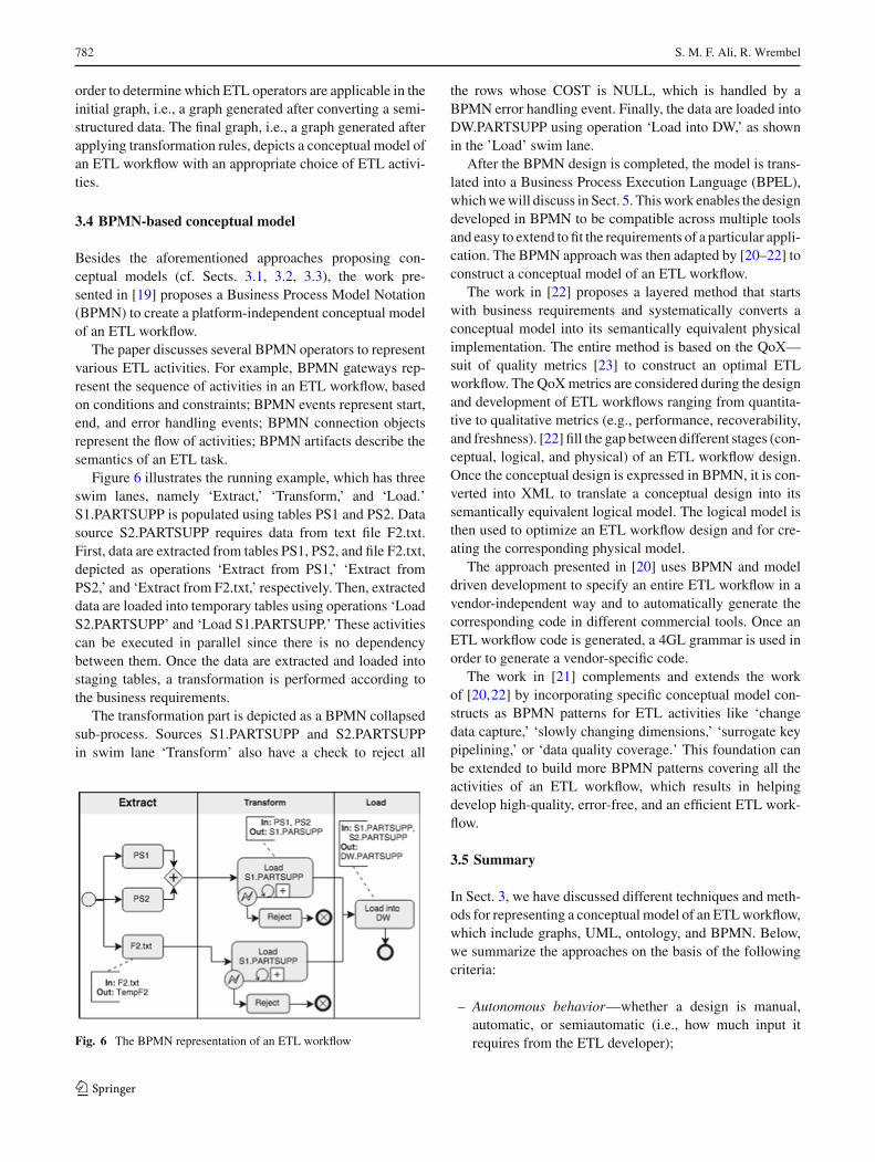
The paper discusses several BPMN operators to representvarious ETL activities. For example, BPMN gateways rep-resent the sequence of activities in an ETL workflow, basedon conditions and constraints; BPMN events represent start,end, and error handling events; BPMN connection objectsrepresent the flow of activities; BPMN artifacts describe thesemantics of an ETL task.
Figure 6 illustrates the running example, which has threeswim lanes, namely ‘Extract,’ ‘Transform,’ and ‘Load.’S1.PARTSUPP is populated using tables PS1 and PS2. Datasource S2.PARTSUPP requires data from text file F2.txt.First, data are extracted from tables PS1, PS2, and file F2.txt,depicted as operations ‘Extract from PS1,’ ‘Extract fromPS2,’ and ‘Extract from F2.txt,’ respectively. Then, extracteddata are loaded into temporary tables using operations ‘LoadS2.PARTSUPP’ and ‘Load S1.PARTSUPP.’ These activitiescan be executed in parallel since there is no dependencybetween them. Once the data are extracted and loaded intostaging tables, a transformation is performed according tothe business requirements.
The transformation part is depicted as a BPMN collapsedsub-process. Sources S1.PARTSUPP and S2.PARTSUPPin swim lane ‘Transform’ also have a check to reject all
Fig. 6 The BPMN representation of an ETL workflow
the rows whose COST is NULL, which is handled by aBPMN error handling event. Finally, the data are loaded intoDW.PARTSUPP using operation ‘Load into DW,’ as shownin the ’Load’ swim lane.
After the BPMN design is completed, the model is trans-lated into a Business Process Execution Language (BPEL),whichwewill discuss in Sect. 5. Thiswork enables the designdeveloped in BPMN to be compatible across multiple toolsand easy to extend to fit the requirements of a particular appli-cation. The BPMN approach was then adapted by [20–22] toconstruct a conceptual model of an ETL workflow.
The work in [22] proposes a layered method that startswith business requirements and systematically converts aconceptual model into its semantically equivalent physicalimplementation. The entire method is based on the QoX—suit of quality metrics [23] to construct an optimal ETLworkflow. The QoXmetrics are considered during the designand development of ETL workflows ranging from quantita-tive to qualitative metrics (e.g., performance, recoverability,and freshness). [22] fill the gap between different stages (con-ceptual, logical, and physical) of an ETL workflow design.Once the conceptual design is expressed in BPMN, it is con-verted into XML to translate a conceptual design into itssemantically equivalent logical model. The logical model isthen used to optimize an ETL workflow design and for cre-ating the corresponding physical model.
The approach presented in [20] uses BPMN and modeldriven development to specify an entire ETL workflow in avendor-independent way and to automatically generate thecorresponding code in different commercial tools. Once anETL workflow code is generated, a 4GL grammar is used inorder to generate a vendor-specific code.
The work in [21] complements and extends the workof [20,22] by incorporating specific conceptual model con-structs as BPMN patterns for ETL activities like ‘changedata capture,’ ‘slowly changing dimensions,’ ‘surrogate keypipelining,’ or ‘data quality coverage.’ This foundation canbe extended to build more BPMN patterns covering all theactivities of an ETL workflow, which results in helpingdevelop high-quality, error-free, and an efficient ETL work-flow.
3.5 Summary
In Sect. 3, we have discussed different techniques and meth-ods for representing a conceptual model of an ETLworkflow,which include graphs, UML, ontology, and BPMN. Below,we summarize the approaches on the basis of the followingcriteria:
– Autonomous behavior—whether a design is manual,automatic, or semiautomatic (i.e., how much input itrequires from the ETL developer);
123

From conceptual design to performance optimization of ETL workflows: current state of… 783
– DSs format—what kind of data sources are supported,i.e., structured, unstructured, or semi-structured;
– UDF support—whether user-defined functions are sup-ported;
– Quality metrics—whether quality metrics guide thedesign of an ETL workflow;
– Unified model—whether an ETL design is easily trans-lated from a conceptual model into its semanticallyequivalent logical model and whether it can be imple-mented using any ETL framework.
1. Graph-based approaches [7,8]
Pros:• Widely accepted graph-based models are used,which help the ETL developer to outline aconceptual model of an ETL workflow in a stan-dardized way.
• They present the first steps toward translating aconceptual model of an ETL workflow into itssemantically equivalent logical model.
Cons:• No autonomous behavior—the ETL developerhas to manually derive ETL transformations andinter-attribute mappings at a conceptual level.
• Structured data only—only the structured inputdata sources are supported, and there is nodiscussion on how to handle unstructured orsemi-structured data sources.
• No UDF support and quality metrics—the oper-ators and templates for traditional ETL tasks areproposed; there is no support for UDFs; qualitymetrics are not taken into consideration whileconstructing a conceptual model.
• Challenges—an ETL design may become com-plex due to the absence of a standard modelinglanguage and treating attributes as ‘first-class cit-izens’ in the model.
2. UML-based approach [14]
Pros:• Unified model—a method is proposed to stan-dardize the conceptual design of an ETL work-flow (UML is a standard modeling language).
Cons:• No autonomous behavior—the ETL developerhas to provide input at each stepof the conceptualdesign.
• Structured data only—only the structured inputdata sources are supported.
• No UDF support and quality metrics—no sup-port for user-defined functions and quality met-rics.
3. Ontology-based approaches [15,17,18,24]
Pros:• Semi-autonomousbehavior—theontology-basedmodels propose semiautomaticmethods to designa conceptual model of an ETL workflow ina step-by-step manner (based on reasoners onontologies, it is possible to derive ETL transfor-mations automatically).
• Structured&semi-structureddata—[15,18] focuson structured data only and [17] focus also onsemi-structured data.
Cons:• No UDF support and quality metrics—UDFsare not supported; quality metrics are not takeninto consideration while constructing a concep-tual ETL model.
• Unified model—an ontology-based conceptualdesign cannot be directly translated into itssemantically equivalent logical model. It requiresa fair amount of effort from the ETL developer totranslate the design.
• Challenges—manually creating an ontology anddefining the relationships among the ontologyelements is a difficult and time-consuming task.Constructing an ontology manually requires highcorrectness and detailed description of datasources, thus if an ontology is created manuallyit becomes more prone to errors.
4. BPMN-based approaches [19–22]
Pros:• Semi-autonomousbehavior—[21] introducevar-ious BPMN patterns as constructs for frequentlyused ETL operators and activities.
• Quality metrics & unified model—[22] pro-pose a systematic method to translate businessrequirements into a conceptual model and con-ceptual model into its semantically equivalentlogical model, based on quality metrics. [20] useBPMN andmodel driven development approachto develop vendor-independent design of anETLworkflow.
Cons:• No UDF support.• Challenges—converting conceptual model intoits equivalent logical and physical implementa-tion requires ETL developers to have specific
123

784 S. M. F. Ali, R. Wrembel
knowledge and hands-on experience in BPMNand BPEL.
To conclude, the graph-based models can be used to rep-resent a complex conceptual design of an ETL workflow byusing standard notations, whereas, for simpler ETL work-flows, approaches based on UML, ontology, and BPMNare well suited. Such models reflect business requirementsas well as provide technical perspective of the problem.Nonetheless, there is a need for a single agreed unifiedmodel,easy to validate and benchmark an ETL design for its qual-ity objectives. Also all the discussed approaches require theETL developer to extensively provide some input during thedesign phase of an ETL workflow, as well as require techni-cal knowledge frombusiness users to understand and validatean ETL design. Furthermore, despite the fact that multipleapproaches have been proposed, the research community hasnot yet agreed upon the standard notation for representing aconceptual model of an ETL workflow.
4 Logical model
The next step in ETL development life cycle is a logicaldesign of an ETL workflow. A logical design describesdetailed description of an ETL workflow such as relation-ships among the involved processes with participating datasources, a description of primary data flow from source datastores into a DW, including an execution order of ETL activ-ities as well as an execution schedule of an entire ETLworkflow. A recovery plan and a sequence of steps in caseof recovery from a failure are also devised during a logicaldesign of an ETL workflow.
In this section, we will discuss approaches to a logicaldesign of an ETL workflow.
4.1 Graph-based logical model
Initial approaches to designing a logical model of an ETLworkflow are based on graphs. The work presented in [25]proposes a formal logical model as a graph called Archi-tecture Graph. The graph shown in Fig. 7 illustrates anETL workflow as a set of ETL activities and a flow of databetween these activities. The nodes in the graph representETL activities, record sets, and attributes, whereas the edgesrepresent different types of relationships among ETL activ-ities. For example, Fig. 7 illustrates activities ‘SK_T’ and‘$2e.’ Parameter ‘PKEY’ is mapped to attribute ‘PKEY’of activity ‘SK_T’ and parameter ‘SKEY’ is mapped toattribute ‘SKEY’ via regulator relationship. The regulatorrelationship denotes that external data provider is used topopulate the attribute. The provider relationships denote thedata flow from source record sets toward the target recordset. The part-of relationship denotes the relationship between
Fig. 7 Architecture Graph of an ETL workflow
attributes and activity, record set, or function. The instance-of relationship describes a relationship between data typesand attributes.
[25] propose the following steps to construct a logicalmodel of an ETL workflow as the Architecture Graph:
1. Incorporate structured entities, i.e., activities and recordsets in a graph along with all the attributes. For example,Fig. 7 illustrates S2.PARTSUPP as a structured entityalong with its attributes, i.e., DEPT, COST, QTY, DATE,SUPPKEY, and PKEY.
2. Connect ‘Activity nodes’ with their respective attributesthrough a part-of relationship. For example, in Fig. 7‘Activity nodes’ ‘SK_T’ and ‘$2e’ are connected withtheir respective attributes as the part-of relationship thatis depicted as a connector with a diamond. The ‘IN’ and‘OUT’ labels on an activity represent that the attributesbelong to the input and output schema of an activity,respectively.
3. Incorporate data and function types using instance-ofrelationships. For example, data types ‘US_Date’ and‘US_Dollar’ are connected to their respective attributes‘DATE’ and ‘COST’ as instance-of relationships, depictedin Fig. 7.
4. Construct the regulator relationships. For example, inFig. 7, regulator relationships among the parameters ofthe activities and attributes are depicted with simple dot-ted edges.
5. Establish provider relationships that capture the flow ofdata from source to target. For example, the data flowfrom source attributes toward target attributes is depictedas bold solid arrows in Fig. 7.
The proposed graph is considered as a formal logicalmodel of an ETL workflow. In [26,27], the authors usedthe aforementioned model along with a formal LogicalData Language (LDL) to define the semantics of each ETLactivity. [27] also mention the reusability framework to com-
123

From conceptual design to performance optimization of ETL workflows: current state of… 785
Fig. 8 Parameterized DAG(DAG-P) for the example ETLworkflow
pliment the generic behavior of the proposed model, whichis achieved through a meta-model layer (ML) and a templatelayer (TL) as discussed in [7] (cf. Sect. 3.1). The authors alsopropose a user-friendly graphical tool to facilitate the ETLdeveloper to design an ETL workflow.
[22] propose to construct a logical model of an ETLwork-flow using a method to parameterize a Directed AcyclicGraph (DAG), called hereParameterizedDAG (DAG-P). TheDAG is created by translating a BPMN-based conceptualmodel, as mentioned in Sect. 3.4. DAG-P operations, trans-formations, and data stores are represented as vertices of thegraph. Edges represent data flows from a source data storeto a target data store. The parameters in DAG-P are used toincorporate business requirements [23], physical resources(needed for an ETL workflow execution), and other genericcharacteristics (such as visualization) of an ETL workflow.Figure 8 shows a part of the running example as DAG-P. Inthis figure, data are extracted from S2.PARTSUPP, ‘SK_T’generates a surrogate key, ‘A2E Date’ converts the DATE toEuropean format, ‘$2e’ converts the COST to Euros, andfinally, data are loaded into DW.PARTSUPP. The parametersdepict that the ‘Populate PARTSUPP Process’ should runevery 15min, has a mean time to recover MTTR 2min, anduses 2 CPUs. The DAG-P logical model is represented usingXML notation, called the xLM model.
The xLM model describes different naming standardsto represent DAG-P in an XML notation. For example,<design/> represents all the elements in an ETL graph,<node/> represents a vertex, and <edge/> represents adata flow in an ETL graph connecting two vertices. The<properties/>, <resources/>, and <features/> representdifferent parameters to identifyQoXmetrics in anETLwork-flow.
4.2 From conceptual to logical model
The work presented in [28] proposes a set of steps totransform a conceptual model of an ETL workflow to itscorresponding logical model. The models are representedby graphs called Conceptual Graph and Architecture Graph,respectively. The following steps map a conceptual modelinto a logical model:
1. Identify data stores and transformations required in anETL workflow and describe inter-attribute mappingsbetween source and target data stores.
2. Determine ‘Stages’ to identify the proper order of activ-ities in a conceptual model to assure a proper placementof activities in a logical model.
3. Follow the following five-step method in order to trans-late a conceptual model into its corresponding logicalmodel:
(a) Simplify a conceptual model such that only requiredelements are present in the model.
(b) Map the concepts of a conceptual model into datasources in a logical model such that part-of rela-tionships do not change. The part-of relationshipdenotes the relationship between attributes and activ-ity, record set, or function.
(c) Map transformations defined in a conceptual modelto logical activities and then determine the order ofexecution of the ETL activities.
(d) Represent ETL constraints with separate activities ina logical model and determine their execution order.
(e) Generate a schema involved in a logical model usingthe algorithm proposed in [12] in order to assure thatsemantics of the involved concepts does not changeeven after changing the execution order of tasks in anETL workflow.
As discussed in Sect. 3.4, the work in [22] proposes amethod that covers all stages of an ETL workflow design,i.e., from gathering business requirements to designing aconceptual model and finally translating it into an XML-based logicalmodel as aDAG-P. The reason behind choosingXML is its ability to easily transform one XML model(conceptual) into another XML model (logical). The paperproposes a semiautomatic approach to convert a concep-tual model represented using XPDL into the xLM model(XML representation of a logical workflow). For example,the XPDLworkflow ismapped into xLM<design/>, XPDLtransitions—into xLM <edges/>, XPDL activities—intoxLM<nodes/>. TheXML representation of a logicalmodelis used for creating a physical model of an ETL workflow,which is discussed in Sect. 5.
123

786 S. M. F. Ali, R. Wrembel
4.3 Summary
In this section, we have discussed a graph-based logicalrepresentation of an ETL workflow and steps to translatea conceptual model into its semantically equivalent logicalmodel. We have outlined step-by-step methods to formu-late a graph-based logical model of an ETL workflow. Thediscussed methods are not trivial to adopt and require asubstantial amount of manual effort and background knowl-edge from the ETL developers. Below, we summarize theapproaches on the basis of the criteria described in Sect. 3.5.
1. Graph-based approaches [22,25–27,29]
Pros:• Quality metrics—[22] propose annotations toincorporate quality metrics in an ETL workflowfor its efficient and reliable execution.
• Unified model—[27] propose a reusable frame-work that supplements a generic behavior of alogicalmodel by defining semantics of eachETLactivity in a graph. [22] propose a logical modelas a graph, which is implemented in XML andcan be used in any XML-based framework.
Cons:• No autonomous behavior—the discussed meth-ods require theETLdeveloper either tomanuallyconstruct a logical model from a given concep-tual model or to provide an extensive amount ofinput to the system, to generate a logical modelfrom a conceptual model.
• No UDF support.• Challenges—the discussed approaches demanda substantial amount of input from the ETLdeveloper. For example, such an input is requiredin: (1) the taskof identifying stages (c.f. Sect. 4.2)to make sure the activities are in a proper orderand (2) the task of defining themappings to trans-late a conceptual model to its equivalent logicalmodel. Such tasks are not trivial in nature andare prone to errors.
From the above discussion,we can conclude that there stillexists a need to develop a fully or semiautomatic intelligentsystem that would guide the ETL developer to produce a log-ical design of an ETL workflow satisfying some predefinedquality criteria.
5 Physical implementation
Having developed a conceptual and a logical model of anETL workflow, its physical model has to be produced. A
physical model describes and implements the specificationsand requirements presented in a conceptual and a logicalmodel.
5.1 Implementation based on reusable templates
The work in [30] proposes a method for mapping a logicalmodel of an ETL workflow into its corresponding physicalmodel. A logical model is formulated as a state-space prob-lem,where states are a set of physical level scenarios and eachstate has a different cost. An initial state of the state-spaceproblem is generated by converting each logical activity toits corresponding physical activity using a library of reusabletemplates. The library consists of both logical- and physical-level templates. The templates include a set of properties,require some input parameters, and thus are able to be cus-tomized according to a particular ETL scenario.
Let Lt denote a set of logical templates and Pt bea set of physical templates in a template library. Con-sider logical activity $2e that converts dollars to euros forS2.PARTSUPP in the running example. First, logical tem-plate ‘CurrencyConvert_Lt ’ (to convert currency amount)is picked from Lt . Then, an input and output schema andan attribute over which the conversion will take place areassigned to the selected template. For example, the requiredinput and output schema will be S2.PARTSUPP (PKEY,SUPPKEY, DATE, QTY, COST, SKEY) and attribute COSTwill be passed for conversion. Finally, the selected template‘CurrencyConvert_Lt ’ is mapped into a valid physical tem-plate from Pt .
Multiple versions of the solution can be generated byselecting different physical templates, provided all con-straints and conditions of the selected physical template aresatisfied.
5.2 Implementation based on BPEL
A BPMN approach [19] discussed in Sect. 3.4 implements aBPMN-based conceptual model into Business Process Exe-cution Language (BPEL). BPEL is a standard executablelanguage for specifying interactions with Web services,based onXML.BPELhas fourmain sections: ‘partnerLinks,’‘variables,’ ‘faultHandlers,’ and ‘process.’ In order to trans-late BPMN into BPEL, first the basic attributes are mappedsuch as business process name and related namespaces aremapped to the ‘process name’ in BPEL. Then, ETL tasks ina BPMN are represented as the type of ‘services’ and aremapped into the ‘partnerLinks’ in BPEL.
For example, Fig. 9, which is an extract from Fig. 6,illustrates ETL activities as (extract from) ‘PS1,’ (extractfrom) ‘PS2,’ and (extract from) ‘F2.txt.’ These activities aremapped to ‘partnerLinks’ in BPEL. BPMN properties thatsupport an ETL workflow such as ‘TempF2’ in Fig. 6 are
123

From conceptual design to performance optimization of ETL workflows: current state of… 787
Fig. 9 BPMN representation of an ‘Extract’ Step
stored in BPEL ‘variables.’ The error end events in a BPMNare mapped to ‘faultHandlers’ event in BPEL. Finally, the‘process’ section in BPEL contains the description of theETL activities that are included in an ETL workflow.
5.3 Implementation based on XML
[22] propose to model an ETL workflow as an ETL graphencoded in XML representation (as described in Sects. 3, 4).To translate an XML-based logical model to its correspond-ing physical implementation, the authors use an appropriateparser. For example, an XML encoded logical model can betranslated into a physical implementation format understand-able by Pentaho Data Integrator (PDI), as follows:
1. element <design/> maps into ‘job’ activity, and if<design/> element is nested, then it maps into ‘trans-formation’ activity in PDI,
2. element <node/> maps into ‘step,’3. elements <name/> and <optype/> map into ‘name’
and ‘type’ of ‘step,’ respectively,4. element <type/> of node describes the type of an ETL
activity, e.g., a data store or an ETL operator in ‘step,’5. element<edge/> specifies the order and interconnection
of ‘step,’6. element <properties/> specifies the physical properties
of the ‘step.’
‘job,’ ‘step,’ ‘name,’ and type of step’ are artifacts in PDI.Hence, using the aforementioned mapping rules and theappropriate parser, the physical implementation of a XMLencoded logical model is easily generated.
5.4 Summary
In this section, we have examined the methods and tech-niques to translate logical models of an ETL workflow intotheir corresponding physical implementations using reusabletemplates, engine-specific XML parser, and BPEL. Theadvantages and disadvantages of the discussed approachescanbe summarizedbasedon themetrics described inSect. 3.5as follows.
1. Reusable templates approach [30]
Pros:• Semi-autonomous behavior—the techniquesthat physically implement a graph-based logicalmodel use a library of reusable (possibly error-free and efficient) templates; a number of anETLworkflowvariantsmay be generated by selectingdifferent physical templates.
• UDF support—UDFs are supported as black-box ETL activities and are considered duringimplementation and performance optimization.
Cons:• Structured data—only structured data sourcesare supported.
• Quality metrics—only execution and perfor-mance cost as quality metrics are considered.
• Unifiedmodel—theETLdeveloper has tomanu-ally translate a logical model into its correspond-ing physical implementation if a template is notalready provided for a certain ETL activity. Fur-thermore, the templates are platform dependent,which limits their application.
• Challenges—a limited set of logical and physi-cal templates is provided.
2. BPEL-based approach [19]
Pros:• Semi-autonomous behavior—BPEL is used tophysically implement a BPMN-based logicalmodel; mapping rules are required to implementa BPMN-based model into BPEL.
• Unified model—the physical implementation isdone using BPEL and thus is platform indepen-dent as an ETL processes can be exposed as aWeb service.
Cons:• Structured data—only structured data sourcesare supported.
• No UDF support.• Challenges—the ETL developermust have priorknowledge of BPEL and tools that supportBPEL-based ETL workflows.
3. XML-based approach [22]
Pros:• Semi-autonomous behavior—a step-by-stepmethod is proposed to generate a physicalimplementation of an XML-based logicalmodel using engine-specific XML parser, butthe ETL developer has to provide the mappingrules to implement an ETL workflow.
123

788 S. M. F. Ali, R. Wrembel
• Quality metrics—the performance, freshness,recoverability, and reliability quality metrics areaddressed.
• Unified model—the logical design is createdin the XML format. Since most of the ETLtools support XML, it is easy to generate acorresponding physical implementation usingexisting tools.
Cons:• Structured data—only structured data sourcesare supported.
• No UDF support.• Challenges—generating a physical implementa-tion of a workflow from its XML-based logicalmodel requires a set of carefully defined rules.
To conclude, the discussed methods require extensiveamount of input from the ETL developer to execute a trans-lation of a logical model into its physical representation.Although a few approaches have been proposed in this field,there is a need for a framework that automatically or semi-automatically translates a logical model into its physicalimplementation with minimum or no human support.
6 Optimization of an ETL workflow
As discussed in Sect. 1, an ETL workflow has a complexstructure because it comprises many different ETL activities,which may be implemented in various ways, e.g., relationaloperators or UDFs. Each of these activities may have fluctu-ating execution time that increases with respect to the size ofincoming data. Therefore, minimizing the execution time isof particular importance. In this section, we will discuss dif-ferent research approaches and commercial tools that supportperformance optimization of ETL workflows.
6.1 State-space approach for optimizing an ETLworkflow
[12] present a concept to reduce the execution cost eitherby decreasing the total number of activities or by changingthe order of activities in an ETL workflow. To this end, astate-space search problem is defined, where each state in asearch space is a Directed Acyclic Graph (DAG). In a DAG,activities are represented as graph nodes and relationshipsamong nodes are represented as directed graph edges. Tofind an optimal ETL workflow, new states are generated thatare semantically equivalent to the original state. A transitionfrom an original state to a new state may involve swappingtwo activities, factorizing/distributing two activities, merg-ing, or splitting activities.
Fig. 10 ETL workflow before applying operation distribute
Fig. 11 ETL workflow after applying operation distribute
To illustrate the generation of a semantically equivalentnew state using operation distribute (i.e., to distribute thedata flow in an activity into different data flows rather thanoperating over a single data flow), consider a conceptualmodel of the running example as depicted in Fig. 10. Thedata are propagated into a DW in two parallel flows passingthrough different activities and are finally unified at Activity10. Then, in Activity 11, the flow checks for the value ofattribute QTY before loading data into a DW. This activity ishighly selective; therefore, it is beneficial to push the activityto the beginning of the flow and distribute the activity intotwo parallel flows. Figure 11 shows Activity 11_1 and Activ-ity 11_2 after applying the distribute operation to Activity 11in Fig. 10. This approach reduces the total cost of the flowwithout changing the semantics of the ETL workflow.
A work of [31] extends that of [12] w.r.t. generating anoptimal ETL workflow in terms of performance, fault toler-ance, and freshness, as described in [23]. In order to achievequality objectives, the approach applies three new transitions,namely partition, add_recovery_point, and replicate. parti-tion is used to parallelize an ETL workflow to achieve betterperformance. add_recovery_point and replicate are used toprovide a workflow persistence and recovery in case of afailure.
To generate a search space, the ‘exhaustive search (ES)’algorithm is used [12]. Next, the search space is pruned byusing a cost model and different heuristics for performance,reliability, and recoverability metrics. Once the state-spacesearch problem is constructed using the ES algorithm, heuris-tics and greedy algorithms are used to reduce and explore thesearch space to get an optimal ETL workflow.
[30] also model an ETL workflow as a state-space searchproblem and apply sorters in a graph node. Sorters changethe order of input tuples, because in some cases the orderplays an important role in an improved execution of an ETL
123
From conceptual design to performance optimization of ETL workflows: current state of… 789
activity. In order to obtain the optimal solution, the ‘exhaus-tive ordering (EO)’ algorithm is used. EO takes a logicaldesign of an ETL workflow as an input in the form of a DAGand computes its signature and its computing cost. The sig-nature is a string representation of a physical design of anETL workflow. To represent a workflow (i.e., a graph) as astring, the following rules are proposed: a@p—the physicalimplementation of ‘p’ of logical activity ‘a,’ . (dot)—namesof activities forming a linear path separated by dot (.), //—concurrent activities delimited by ‘//’ and each path enclosedin parenthesis, a_b(A,B)—a sorter placed among activity ‘a’and ‘b’ based on attributes ‘A’ and ‘B,’ V!A—a sorter ontable ‘V’ based on attribute ‘A.’ Based on the rules, an ETLworkflow shown in Fig. 10 can be represented in terms of thefollowing signature:
(([email protected]@NN) // ([email protected])). [email protected]
In the signature, activities 1, 3, 4, and 5 (in Fig. 10) form a lin-ear path in the upper level flow and activities 2, 6, 7, 8, and 9form a linear path in the lower level flow. Both the upper andthe lower level flows are concurrent and therefore are sepa-rated by ‘//.’ (([email protected]@NN) denotes that activity 4 isaggregated based on the date function ‘DT’ and activity 5 per-forms a not null check ‘NN.’ ([email protected]))[email protected] that activity 7 applies projection ‘PO’ on attributeDEPT as it is not required by a DW. Finally, both flows aremerged based on nested loop ‘NL’ at activity 10.
Once the signature is computed, the EO algorithm gen-erates all possible states by placing sorters at all possiblepositions. The EO algorithm then uses all possible combina-tions of different physical implementations for each activity.Finally, it chooses a state with minimum execution cost asthe optimal physical implementation.
6.2 Dependency graph for optimizing an ETL workflow
The optimization concept contributed in [11] draws upon theidea of rearranging tasks (activities) in an ETL workflow(as proposed in [12]), in order to construct a more efficientvariant of thisworkflow.The following assumptions aremadein [11]:
– an ETL workflow is represented as a DAG,– every task has associated a selectivity (defined as a ratio:output/input data volume),
– every task has associated a cost, which is a function ofan input data size,
– a workflow is rearranged by means of operations: swap,factorize/distribute, merge/un-merge (as in [12]),
– a workflow rearrangement is guided by an optimizationrule that moves (if possible) more selective tasks to thebeginning of the workflow.
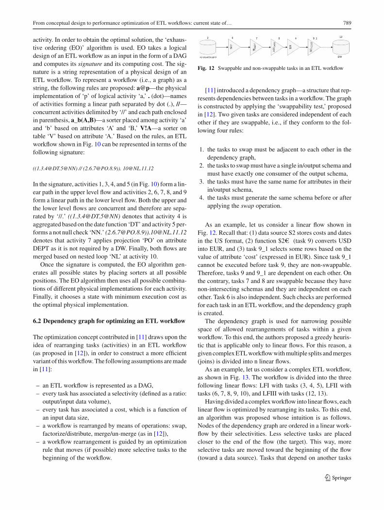
Fig. 12 Swappable and non-swappable tasks in an ETL workflow
[11] introduced a dependency graph—a structure that rep-resents dependencies between tasks in aworkflow. The graphis constructed by applying the ‘swappability test,’ proposedin [12]. Two given tasks are considered independent of eachother if they are swappable, i.e., if they conform to the fol-lowing four rules:
1. the tasks to swap must be adjacent to each other in thedependency graph,
2. the tasks to swapmust have a single in/output schema andmust have exactly one consumer of the output schema,
3. the tasks must have the same name for attributes in theirin/output schema,
4. the tasks must generate the same schema before or afterapplying the swap operation.
As an example, let us consider a linear flow shown inFig. 12. Recall that: (1) data source S2 stores costs and datesin the US format, (2) function $2e (task 9) converts USDinto EUR, and (3) task 9_1 selects some rows based on thevalue of attribute ‘cost’ (expressed in EUR). Since task 9_1cannot be executed before task 9, they are non-swappable.Therefore, tasks 9 and 9_1 are dependent on each other. Onthe contrary, tasks 7 and 8 are swappable because they havenon-intersecting schemas and they are independent on eachother. Task 6 is also independent. Such checks are performedfor each task in an ETL workflow, and the dependency graphis created.
The dependency graph is used for narrowing possiblespace of allowed rearrangements of tasks within a givenworkflow. To this end, the authors proposed a greedy heuris-tic that is applicable only to linear flows. For this reason, agiven complexETLworkflowwithmultiple splits andmerges(joins) is divided into n linear flows.
As an example, let us consider a complex ETL workflow,as shown in Fig. 13. The workflow is divided into the threefollowing linear flows: LFI with tasks (3, 4, 5), LFII withtasks (6, 7, 8, 9, 10), and LFIII with tasks (12, 13).
Havingdivided a complexworkflow into linear flows, eachlinear flow is optimized by rearranging its tasks. To this end,an algorithm was proposed whose intuition is as follows.Nodes of the dependency graph are ordered in a linear work-flow by their selectivities. Less selective tasks are placedcloser to the end of the flow (the target). This way, moreselective tasks are moved toward the beginning of the flow(toward a data source). Tasks that depend on another tasks
123

790 S. M. F. Ali, R. Wrembel
Fig. 13 Logical linear division of a complex ETL workflow
T must be placed to the right of T . This way, the dependen-cies between tasks represented in the dependency graph arerespected.
Having optimized the linear flows, the final step is to com-bine the flows into larger linear flows that include all the tasksprocessing data from the source to the destination. For exam-ple, the linear flows fromFig. 13 are combined into two largerlinear flows—the first one is composed of [LFI, LFIII] andthe second one is composed of [LFII, LFIII].
Next, each combined linear flow is optimized by rearrang-ing its tasks, as described above. There are tasks that may bemoved from a given linear flow LFm to the next linear flowLFn , i.e., in the direction toward the end of a workflow. Suchtasks are called forward transferable. There are also tasksthat may be moved in the opposite direction, i.e., toward thebeginning of a workflow. They are called backward transfer-able. An execution order within a combined linear flow isdetermined by the order implied by the dependency graph.
For example, in Fig. 13 tasks 5 and 9 have the same seman-tics (selecting rows with not null costs). Therefore, they canbemoved forward to the beginning of linear flow III, such thatthe linear flow will be composed of tasks (5_9, 12, 13). Task5_9 is a new task created by the factorize operator, havingthe same semantics as 5 and 9. Similarly, task 12 (selectingrows based on the value of attribute QTY) can be moved toLFI and LFII by applying the distribute operator.
Having constructed the combined linear flows, each com-bined flow is optimized by and algorithm whose intuitionis as follows. All possible rearrangements of backward- andforward-transferable tasks are analyzed, and for eachof them,an execution cost of the combined linear flow is computed.Next, the rearrangement with the lowest cost is selected.
6.3 Scheduling strategies for optimizing an ETLworkflow
[9] propose a solution to optimize the performance of anoffline batch ETL workflow in terms of execution time andmemory consumption without the loss of data. To this end,a multi-threaded framework with incorporated ETL sched-uler is presented, where each node of an ETL workflow isimplemented as a thread. The proposed frameworkmonitors,
schedules, and guarantees the correct execution of an ETLworkflow based on the proposed scheduling strategies suchas ‘minimum cost prediction (MCP),’ ‘minimum memoryprediction (MMP),’ and ‘mixed policy (MxP).’
The MCP scheduling strategy is proposed to improve theperformance of an ETL workflow by reducing its executiontime. TheETL scheduler prioritizes activities to be scheduledat each step that have the largest volume of input data toprocess at that time. As a result, the activity with the largestinput queue is able to process all datawithout any interruptionfrom the ETL scheduler.
The MMP scheduling strategy is proposed to improvememory consumption by scheduling activities at eachstep that have the highest consumption rate (consumptionrate=number of rows consumed/processing time of inputdata). As a result, the ETL scheduler maintains a data vol-ume low in a system by scheduling the flow of activitieswhenever an input queue is exhausted due to higher memoryconsumption of the activity.
The MxP strategy is proposed to combine the benefitsof MCP and MMP including operating system’s defaultscheduling strategy (i.e., round-robin) by exploiting paral-lelism within an ETL workflow.
A set of scheduling policies is assessed for the executionof an ETL workflow. The results of incorporating schedulingpolicies are as follows: (1) MCP outperforms other schedul-ing strategies w.r.t. execution time, (2) MMP is better w.r.t.average memory consumption, and (3) MxP, which incor-porates multiple scheduling strategies (e.g., MCP, MMP,or round-robin) by splitting an ETL workflow, achievesbetter time performance. The better time performance isachieved by either prioritizing memory intensive activitiesor by scheduling an ETL workflow to avoid blocking ETLoperations.
6.4 Reusable patterns for optimizing an ETL workflow
[32] present reusable patterns, as a mean to characterizeand standardize the representation of ETL activities alongwith the strategy to improve the efficiency an ETL workflowexecution. The paper proposes to standardize the represen-tation of frequently used ETL activities that involve a singletransformation (e.g., surrogate key transformation, checkingnull values, and primary key violations), called ETL Parti-cles. ETL activities that perform exactly one job and involveexactly one transformation (e.g., $2e conversion) are calledETL Atoms. ETL Atoms that involve a linear flow of ETLparticles are called ETL Molecules, and an ETL workflow iscalled ETL Compound.
The paper then presents a normal form of ETL activities,e.g., the normal form of activity 8 in Fig. 13 can be repre-sented as follows:
123

From conceptual design to performance optimization of ETL workflows: current state of… 791
Fig. 14 Data parallelism and task parallelism
I(πDEPT ),A2E(DATE),O(NNCOST )
I is the input schema coming from activityπDEPT .A2E is thespecific template activity that converts the format of attributeDATE from American to European. O represents the outputof activity 8 as an input to the next activity NNCOST . Simi-larly, activities 3 to 12 are ETLMolecules and the entire flowin Fig. 13 including activities and record sets represent theETL Compound.
6.5 Parallelism for optimizing an ETL workflow
Besides the aforementioned optimization strategies, incor-porating parallelism in an ETL workflow is another popularstrategy to achieve better execution performance. Parallelismcan be achieved either by partitioning the data into N subsetsand process each subset in parallel sub-flows (data paral-lelism) or by using pipeline parallelism (task parallelism) asshown in Fig. 14.
For a simple ETLworkflow, the data parallelism can workwell. However, for a complex ETL workflow (e.g., nonlin-ear flows or flows with data and compute-intensive tasks),combination of data and task parallelism is required. Hence,a mixed parallelism is beneficial when either communica-tion in a distributed environment is slow or the number ofprocessors is large [33].
6.5.1 Parallelism in traditional data flow
Most of research on ETL workflow parallelism has focusedon a traditional data flow parallelism, from which the mostprominent one is the MapReduce framework [34]. It usesa generic key/value data model to process large-scale datain a parallel environment. MapReduce provides two func-tions, Map and Reduce, both having two input parameters,i.e., (1) a set of input data set in a key/value format and (2) anuser-defined function (UDF). Map assigns a key/value pairto its input data using an UDF and produces a set of out-put key/value pairs. The Reduce function then groups thekey/value pairs of its input data on the basis of keys, andfinally, each group is processed using an UDF. Storage forMapReduce is based on distributed file system calledHadoopDistributed File System (HDFS) [35].
The MapReduce framework has its limitations, i.e., (1) itaccepts a single set of input data set at a time in a key/value
format, (2) it always executes in a strict order, i.e., first Mapand then Reduce, (3) the output data from Map have to bestored into an intermediate file system, which makes dataprocessing slow due to data partitioning and shuffling, and(4) developers have to write a custom code for the Map andthe Reduce functions, which is hard to maintain and reuse.
Another parallel processing framework is PACT [36]. Itis based on the Parallelization Contracts (PACTs), whichconsists of an Input Contract and an optional Output Con-tract. The Input Contract is the generalization of theMap andReduce functions and takes anUDF and one ormore data setsas an input. It also provides an extended set of Input Con-tracts i.e., ‘Cross,’ ‘Math,’ and ‘CoGroup’ functions, whichcomplements Map and Reduce functionality and overcomesthe limitations ofMapReducemodel, i.e., The Input Contractdoes not need to be executed in a fixed order and allows mul-tiple inputs of key/value pairs. The Output Contract denotesdifferent properties of the output data, which are relevant toparallelization. These properties can be either (1) preservinga partitioning property or (2) an ordering property on data thatare generated by an UDF. An input UDF contains the strat-egy (such as partitioning, repartitioning, or broadcasting) forparallelizing in PACT.
For example, let us introduce another concept in our run-ning example, REVIEWS (RID, PKEY, DEPT, REVIEW,SCORE, ENTRYDATE), which stores user reviews alongwith its computed score for each ‘part’ stored in a depart-ment. Now consider analytical query Q, which provides‘parts’ from S1.PARTSUPP having COST greater than someamount, let us say ‘c.’ Query Q joins S1.PARTSUPP withREVIEWS, keeping only ‘parts’ where the review score isgreater than some threshold ‘s,’ and reduces the result set tothe ‘parts,’ which are not present in S2.PARTSUPP for somedepartment ‘d.’
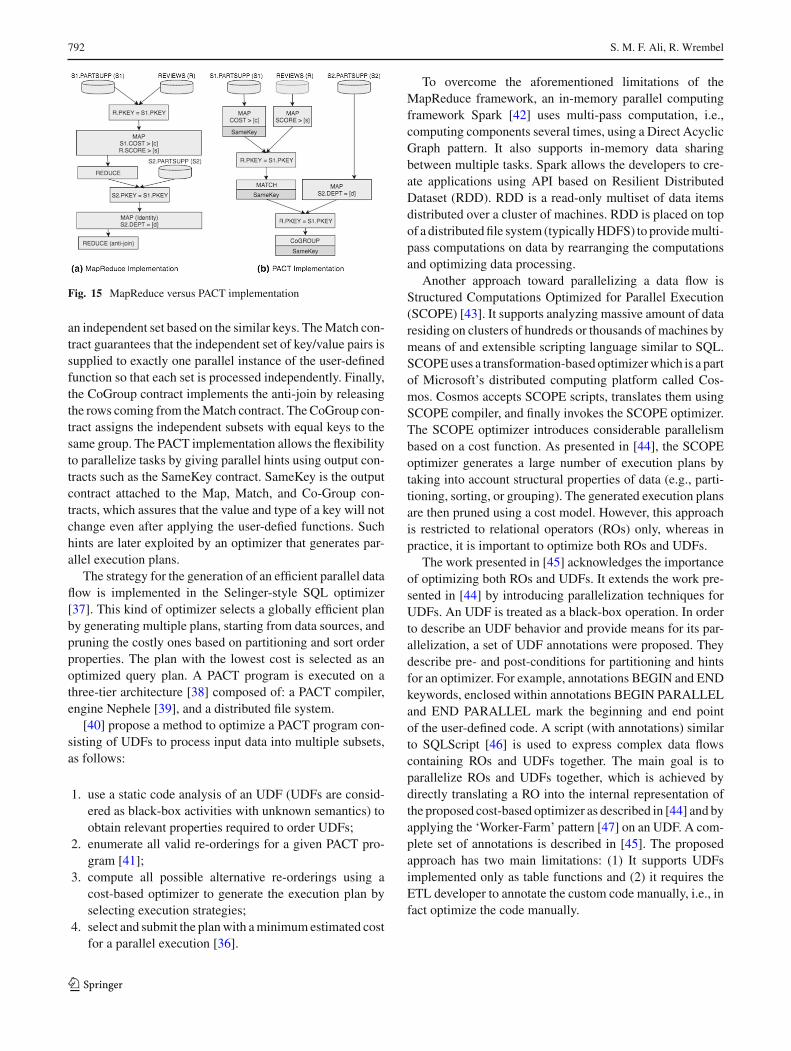
Figure 15 shows query Q as: (a) the MapReduce imple-mentation and (b) the PACT implementation. The MapRe-duce implementation requires two stages of the MapReducejob. The first stage performs a join on the basis of PKEY inS1.PARTSUPP (S1) and REVIEWS (R) and carries out thespecific selection based on S1. COST > ‘c’ and R.SCORE> ‘s.’ The result from the first stage joins with the selec-tion on S2.PARTSUPP (S2) on the basis of S2.DEPT= ‘d’in the Map function of the second stage. The reducer inthis stage performs an anti-join on the result set (when noS2.PARTSUPP row with an equal key is found).
The PACT implementation for the same query Q requiresthree separate user-defined functions (UDFs) attached to theMap contract to perform a selection on data sources S1, R,and S2 instead of a single user-defined function in a MapRe-duce scenario, such that each UDF is executed in parallel.The Match contract replaces the Reduce contract in the orig-inal MapReduce implementation. It matches the incomingkey/value pairs from data sets with the same key and forms
123
792 S. M. F. Ali, R. Wrembel
Fig. 15 MapReduce versus PACT implementation
an independent set based on the similar keys. TheMatch con-tract guarantees that the independent set of key/value pairs issupplied to exactly one parallel instance of the user-definedfunction so that each set is processed independently. Finally,the CoGroup contract implements the anti-join by releasingthe rows coming from theMatch contract. The CoGroup con-tract assigns the independent subsets with equal keys to thesame group. The PACT implementation allows the flexibilityto parallelize tasks by giving parallel hints using output con-tracts such as the SameKey contract. SameKey is the outputcontract attached to the Map, Match, and Co-Group con-tracts, which assures that the value and type of a key will notchange even after applying the user-defied functions. Suchhints are later exploited by an optimizer that generates par-allel execution plans.
The strategy for the generation of an efficient parallel dataflow is implemented in the Selinger-style SQL optimizer[37]. This kind of optimizer selects a globally efficient planby generating multiple plans, starting from data sources, andpruning the costly ones based on partitioning and sort orderproperties. The plan with the lowest cost is selected as anoptimized query plan. A PACT program is executed on athree-tier architecture [38] composed of: a PACT compiler,engine Nephele [39], and a distributed file system.
[40] propose a method to optimize a PACT program con-sisting of UDFs to process input data into multiple subsets,as follows:
1. use a static code analysis of an UDF (UDFs are consid-ered as black-box activities with unknown semantics) toobtain relevant properties required to order UDFs;
2. enumerate all valid re-orderings for a given PACT pro-gram [41];
3. compute all possible alternative re-orderings using acost-based optimizer to generate the execution plan byselecting execution strategies;
4. select and submit the planwith aminimumestimated costfor a parallel execution [36].
To overcome the aforementioned limitations of theMapReduce framework, an in-memory parallel computingframework Spark [42] uses multi-pass computation, i.e.,computing components several times, using a Direct AcyclicGraph pattern. It also supports in-memory data sharingbetween multiple tasks. Spark allows the developers to cre-ate applications using API based on Resilient DistributedDataset (RDD). RDD is a read-only multiset of data itemsdistributed over a cluster of machines. RDD is placed on topof a distributedfile system (typicallyHDFS) to providemulti-pass computations on data by rearranging the computationsand optimizing data processing.
Another approach toward parallelizing a data flow isStructured Computations Optimized for Parallel Execution(SCOPE) [43]. It supports analyzing massive amount of dataresiding on clusters of hundreds or thousands of machines bymeans of and extensible scripting language similar to SQL.SCOPEuses a transformation-based optimizerwhich is a partof Microsoft’s distributed computing platform called Cos-mos. Cosmos accepts SCOPE scripts, translates them usingSCOPE compiler, and finally invokes the SCOPE optimizer.The SCOPE optimizer introduces considerable parallelismbased on a cost function. As presented in [44], the SCOPEoptimizer generates a large number of execution plans bytaking into account structural properties of data (e.g., parti-tioning, sorting, or grouping). The generated execution plansare then pruned using a cost model. However, this approachis restricted to relational operators (ROs) only, whereas inpractice, it is important to optimize both ROs and UDFs.
The work presented in [45] acknowledges the importanceof optimizing both ROs and UDFs. It extends the work pre-sented in [44] by introducing parallelization techniques forUDFs. An UDF is treated as a black-box operation. In orderto describe an UDF behavior and provide means for its par-allelization, a set of UDF annotations were proposed. Theydescribe pre- and post-conditions for partitioning and hintsfor an optimizer. For example, annotations BEGIN and ENDkeywords, enclosed within annotations BEGIN PARALLELand END PARALLEL mark the beginning and end pointof the user-defined code. A script (with annotations) similarto SQLScript [46] is used to express complex data flowscontaining ROs and UDFs together. The main goal is toparallelize ROs and UDFs together, which is achieved bydirectly translating a RO into the internal representation ofthe proposed cost-based optimizer as described in [44] and byapplying the ‘Worker-Farm’ pattern [47] on an UDF. A com-plete set of annotations is described in [45]. The proposedapproach has two main limitations: (1) It supports UDFsimplemented only as table functions and (2) it requires theETL developer to annotate the custom code manually, i.e., infact optimize the code manually.
123

From conceptual design to performance optimization of ETL workflows: current state of… 793
6.5.2 Parallelism in an ETL workflow
Introducing parallelism into an ETL workflow is not a trivialtask. The ETL developer has to decide which activities toparallelize, how much to parallelize, and when to parallelizebefore incorporating parallelism into an ETL workflow.
Task and code parallelism [48] propose a method to exploitparallelism at a code level by introducing strategies for bothtask and data parallelism. A set of constructs is proposed inorder to enable the ETL developer to convert a linear ETLworkflow into its corresponding parallel flow. The constructsare easy to use and do not require complicated modifica-tion of a non-parallel ETL workflow. However, the proposedsolution is code based and requires the ETL developer toconfigure the degree of parallelization. Furthermore, thissolution does not provide any cost model to estimate a per-formance gain.
Parallelizing by means of MapReduce [49,50] present aparallel dimensional ETL framework based on MapReducecalled ETLMR. The focus of ETLMR is on star schema,snowflake schema, slowly changing dimensions (SCDs), anddata-intensive dimensions. The ETLMR processes an ETLworkflow in two stages. In the first stage, dimensions are pro-cessed usingMapReduce tasks. In the second stage, facts areprocessed using another MapReduce task. Dimensions canbe processed by using either of the following strategies: OneDimension One Task (ODOT) and One Dimension All Tasks(ODAT). In ODOT, dimensions are processed by the Maptask using anUDFand then the processed data are propagatedinto a single Reduce task. In the Reduce task, user-definedtransformations are performed on rows and then loaded intoa DW. In ODAT, an output of the Map task is partitioned ina ‘round-robin’ fashion, i.e., the output is processed by allthe Reduce tasks such that each Reduce task receives equalnumber of rows. The uniqueness of dimension key/values ismaintained by using a global ID generator and a ‘post-fixing’method, which merges rows with the same values but differ-ent keys into a single row. To optimize ODOT, keys with thesame values are combined together in the Combiner task, toreduce the communication cost between theMap andReducetasks. Using the single Reduce task can become a bottleneckin case of a data intensive dimension; therefore, ODAT isused to overcome the bottleneck.
Fact processing in ETLMR requires looking up of dimen-sion keys and aggregation (if required). If aggregations arenot applicable, only the Map task is used and the Reducetask is dropped. Otherwise, only the Reduce task is usedsince aggregations must be completed from all the data in theReduce task. Once the fact data are processed, it is loadedinto a temporary buffer where it resides until the buffer is
Fig. 16 ETL workflow partitioning
fully loaded. The Map and Reduce tasks then perform bulkloading in parallel into a DW.
Partitioning and parallelization [51] proposeETLworkflowpartitioning and parallelization, as an optimization method.Vertical and horizontal partitioning is suggested. Verticalpartitioning is impacted by tasks in an ETL workflow andthe following tasks are distinguished: row-synchronized—itprocesses row by row (e.g., filter, lookup, split, data for-mat conversion) and uses a shared cache to move data fromtask to task, block—processing cannot start until all rowsare received by the task (e.g., aggregation), semi-block—receives rows frommultiple tasks andmerges them (e.g., join,set operators); processing of the task starts no sooner than allexpected rows are received. The authors propose to partitionand parallelize an ETL workflow at three levels. First, thewhole ETL workflow is vertically partitioned into multiplesub-workflows—called execution trees. Second, executiontrees are partitioned horizontally and each partition is run inparallel. Third, single tasks in an execution tree are paral-lelized by multi-threading.
Vertical partitioning is executed as follows.AnETLwork-flow analysis is run depth-first and it starts from a data source(the root of an ETL graph). All row-synchronized compo-nents (i.e., the ones that use a shared cache) are added into anew sub-workflow, so that their original order is preserved.If a block or semi-block task is found, then it becomes a rootof a new sub-workflow.
Figure 16 explains the workflow partitioning method.Analyzing the ETL graph starts from data sources. For exam-ple, S1 and S2 create two separate execution trees T1 and T3,respectively. Task 3 is row-synchronized and it is added intoT1, whereas row-synchronized tasks 6, 7, 8, and 9 are addedinto T3. Since task 4 is a block task, it becomes the root ofa new execution tree T2 having activity 5 as its only child.Task 10 is a semi-block task, which forms execution tree T4,composed of tasks 11 and 12.
Once the execution trees are constructed, internal paral-lelization is carried out inside each of the execution trees. Tothis end, input data are partitioned horizontally into n disjointpartitions (n is parameterized), where each partition is pro-cessed by a separate thread. Finally, internal parallelizationis carried out for tasks with a heavy computational load. To
123

794 S. M. F. Ali, R. Wrembel
find such a task, time is measured during which a task doesnot produce any output. If the time is greater than a giventhreshold, then the task becomes a candidate for internal par-allelization. To parallelize a single task, multi-threading isapplied, i.e., an input of the task is divided into n equalsplits, each of which is run by a separate thread. Moving databetween tasks within the same execution tree is implementedby means of a shared cache, whereas moving data betweenadjacent execution trees is implemented by means of copingdata between separate cache (cf. dotted arrows in Fig. 16).
6.6 Quality metrics for ETL workflows
The goal of [23] is to reduce time and cost of ETL design,implementation, and maintenance (DIM) by incorporatingsome quality metrics into an ETL workflow design. A lay-ered approach is proposed for an ETLDIM,where each layerrepresents a logical design, implementation, optimization,and maintenance. At each layer, some metrics are intro-duced (or refined from higher levels) that guide the ETLdeveloper to produce a high-quality workflow. Furthermore,dependencies among metrics that impact DIM are identi-fied and discussed. The following metrics are proposed inthe so-called QoX metric suite: performance, recoverabil-ity, reliability, and maintainability—which characterize anETL workflow as well as freshness—which characterizesprocessed data.
The aforementioned QoX metrics are interrelated andinterdependent, which may lead to a contradictory behav-ior of a workflow. For example, on the one hand, increasingperformance by partitioning and parallelizationmay increasefreshness, but on the other hand, it decreases maintainabil-ity due to a more complex workflow design. The authorsstress that some metrics can be used only at certain levelsof DIM. For example, freshness and reliability can be han-dled at the physical level, but at the conceptual level theirusefulness is questionable; conversely, performance is a per-tinent metric at the conceptual, logical, and physical levelof an ETL workflow design. The interdependencies betweenthe quality metrics have been confirmed by some experi-ments. The authors report that: (1) increasing recoverabilityby means of recovery points decreases performance, as addi-tional disk operations are required to store RPs and (2) theimpact of some optimization techniques on the performancevaries, e.g., increasing processing power does not improveperformance linearly—there are parts for an ETL workloadwhose parallelization impacts performance stronger than theother parts.
6.7 Statistics for workflow optimization
Most of ETL workload optimization methods rely on vari-ous statistics. In [10], the authors provide a framework for
gathering statistics for cost-based workload optimization.To this end, a workload must be divided into parts, calledsub-expressions (SEs). The authors proposed to divide aworkflow into SEs based on division points, which are ETLtasks (activities). The following tasks are used as divisionpoints: (1) materialization of intermediate results, (2) trans-formation of values of an attribute that is derived from thejoin of multiple relations and that is further used in anotherjoin, and (3) an UDF. Then, each SE is optimized indepen-dently. It must be stressed that the proposed framework doesnot deal with generating execution plans or estimating theircosts, i.e., it is assumed that the set of SEs and their optimizedexecution plans exists and are delivered by an ETL optimizermodule.
Finding an optimal execution plan is based on: (1) iden-tifying different possible re-orderings of operators (tasks,activities) in a given SE and (2) estimating their executioncosts, in the spirit of [11,12]. Each operator has a cost func-tion that is based among others on: cardinalities of inputrelations (based onhistograms),CPUanddisk-access speeds,memory availability. The following operators are supported:select, project, join, group-by, and transform.
There aremultiple sets of statistics (called candidate statis-tics set—CSS) suitable for optimizing a given SE. Somestatistics can be computed from others, based on the fol-lowing computation rules:
– the cardinality of the select operator can be estimated ifthe data distribution on a filtering attribute is known,
– for the project operator, output cardinalities and distribu-tions are identical to the input ones,
– the cardinality of a join can be determined from the dis-tributions of the input tables on a join attribute,
– the cardinality of group by is identical to the number ofdistinct values of grouping attributes,
– for the transform operator, output cardinalities and dis-tributions are identical to the input ones,
– if there exists a histogram on any set of attributes of tableT, then the cardinality of T can be computed by addingthe values of buckets,
– if there exists a detailed histogram on attributes A and B,then a histogram for A can be computed by aggregatingbuckets on B.
Each CSS may have a different cost of collecting itsstatistics (e.g., CPU and memory usage). For this reason,a challenging task is to identify and generate a set of statis-tics to be collected by an ETL engine during its execution,such that: (1) the set of statistics can be used to estimatecosts of all possible re-orderings of tasks within a givenSE and (2) time and resource overhead of collecting thestatistics is minimal. The authors identified that this is anNP-hard problem and to solve it they proposed a linear pro-
123

From conceptual design to performance optimization of ETL workflows: current state of… 795
gramming algorithm. Finally, the authors suggested that thewhole ETLoptimizationmethod is divided into the seven fol-lowing steps: (1) identifying optimizable blocks by dividinga workflow into sub-expressions, (2) generating optimizedsub-expressions by means of task reordering, (3) generat-ing candidate statistics sets, (4) determining a minimal set ofstatistics, (5) augmenting an optimized SE by injecting intoit a special component for collecting statistics, (6) runninga SE and gathering statistics, and (7) optimizing the wholeETL workflow by means of cost-based techniques.
6.8 Commercial ETL tools
To the best of our knowledge, only two commercial ETLtools, namely IBM InfoSphere DataStage [52] and Infor-matica PowerCenter [53], provide some simple means ofoptimizing ETL workflows.
In IBM InfoSphere DataStage, the so-called balancedoptimization is used. The optimization is included in the fol-lowing design scenario: (1) an ETL workflow is designedmanually (each task should be elementary, e.g., simple selectfrom one table instead of a join), (2) the workflow is com-piled into an internal representation, (3) optimization optionsare defined by the ETL developer, (4) the balanced opti-mization method is applied, and (5) the optimized workflowis produced to be run. The optimization process is guidedby some parameters/options/hints including: (1) reduce adata volume retrieved from a data source (if possible), i.e.,move data transformations, aggregations, sorting, duplicateremoval, joins, and lookups into a data source, (2) alterna-tively, if possible, move processing into a data target, (3) usebulk loading to target, (4) maximize parallelism, and (5) usenot more than a given number of nested joins.
Informatica PowerCenter implements the so-called push-down optimization. In this optimization, some ETL tasks thatcan be implemented as SQL commands are first identified.Second, these tasks are converted into SQL and executedeither at an appropriate source or target database (dependingon the semantics of the tasks). This approach leverages theprocessing power of a database in which data reside.
Other tools, including AbInitio, Microsoft SQL ServerIntegration Services, and Oracle Data Integrator, supportonly parallelization of ETL tasks, with a parameterized levelof parallelism.
6.9 Summary
In this section, we discussed various approaches to theperformance optimization of an ETL workflow, i.e., state-space search, dependency graphs, scheduling policies, andreusable patterns to optimize and ETL workflow execution.We also presented strategies that use parallelism in order toachieve execution performance in an ETL workflow. Finally,
we presented optimization support available in commer-cial and open-source ETL tools. Below, we summarize theapproaches on the basis of the following criteria:
1. Autonomous Behavior—whether an optimizationmethod is automatic, semiautomatic (i.e., requires inputfrom the ETL developer), or manual;
2. UDFOptimization—whether amethod supports the opti-mization of user-defined functions;
3. Monitoring—whether a method or framework supportsmonitoring an ETL workflow in order to identify perfor-mance bottlenecks;
4. Recommendation—whether a method or framework pro-vides recommendations to improve the implementationof an ETL workflow.
1. State-space-based approaches [10–12,30,31]
Pros:• Optimization techniques based on executioncosts and tasks reordering (similarly as queryoptimization techniques) are applied.
• Semi-autonomous behavior—an input is an ETLworkflow in the form of a graph. A given work-flow is then transformed by an algorithm into amore efficient but semantically equivalent work-flow.
Cons:• No UDF support—the proposed optimizationalgorithms support only basic ETL operators.
• No monitoring and recommendation—the pro-posed frameworks neither monitor ETL work-flows for the performance bottlenecks nor pro-vide hints on how to improve the performanceof a workflow.
• Challenges—one of the biggest challenges is thegeneration of an optimal ETL workflow usingthe proposed algorithms. If an ETL workflowis large and complex, the generation of an opti-mal workflow may take longer than the actualtime of execution of the ETL workflow itself.Moreover, [12,31] are limited to a few transitiontechniques from one state to another and also donot give an account to translate an optimized log-icalmodel to its semantically equivalent physicalimplementation.
2. Scheduling-based approach [9]
Pros:• Scheduling policies are applied to optimize anETL workflow execution time and memory con-sumption.
123

796 S. M. F. Ali, R. Wrembel
• Semi-autonomous behavior—it is mainlyfocused on scheduling of ETL activities; thescheduling algorithm requires an ETL work-flow as an input; the scheduling is based onpredefined policies.
• Monitoring—it monitors the entire ETL work-flow, but only for the purpose of scheduling ETLactivities at the right time; it does notmonitor theactivities to find out performance bottlenecks.
Cons:• No UDF optimization and recommendation—itdoes not specifically optimize the behavior ofan UDF activity if it tends to be a bottleneck inanETLworkflow; the scheduling algorithmdoesnot provide any recommendations to improve aninput ETL workflow.
• Challenges—there is a possibility of losing dataduring scheduling; therefore, the approach willnot be applicable to most of the traditional ETLprocessing.
3. Parallelism-based approaches [48–51]
Pros:• Semi-autonomous behavior—the proposedapproaches give a reasonable account for par-allelizing the ETL activities, but the methodsrequire a considerable amount of input from theETL developer to decide which parts of an ETLworkflow need to be parallelized, how muchto parallelize, and where to put split points inorder to enable parallelism.
• UDF support—themethods proposed in [49,50]support the ETL activities as UDFs but do notsupport their optimization.
Cons:• No monitoring and recommendation—neithermechanisms for monitoring ETL workflows forbottlenecks nor recommendations to improve aninput ETL workflow are supported.
• Challenges—the proposed solutions do not pro-vide any cost model to identify the requireddegree of parallelism. Therefore, the ETL devel-oper has to either perform trial and error methodor execute the ETL transformations using testdata to figure out the required degree of paral-lelism.
4. QoX Suite [23]
Pros:• Analyzes various quality metrics and their interdependencies for an ETL design (at a conceptual
and logical level), implementation, optimiza-tion, and maintenance. The metrics are used forassessing the quality of a workflow.
Cons:• No autonomous behavior—the approach pro-vides only a theoretical framework.
• UDF support—not discussed.• No monitoring and recommendation—neithermethods for monitoring the performance of anETL engine nor the functionality of improvingan ETL design based on analyzing quality met-rics has been discussed.
• Challenges—the biggest challenge is how toefficiently guide the ETL developer through sub-sequent stages of an ETL design, taking intoaccount current values of the proposed metrics.
To conclude, the state-space search approaches [12,31]are considered among the first ones toward the logical opti-mization of an ETL workflow. [12] models the problem asa state-space search problem, where each state in a searchspace is a DAG. An optimal ETL workflow is achieved bychoosing the optimal state from the number of generatedstates that are semantically equivalent to the original state.[31] focus on optimizing an ETL workflow for fault toler-ance, performance, and freshness. These approaches servedas the premise for the optimization of an ETL workflow andwere later utilized by various researchers and specialists inthis particular topic. [11] propose the dependency graph thatis used for narrowing the space of allowed rearrangementsof tasks within a given workflow. Most of ETL workloadoptimization methods presented in this survey rely on vari-ous statistics. In [10], the authors provide a framework forgathering statistics for cost-based workload optimization.
The second group of approaches focuses on strategies thatuse parallelism as a mean for increasing ETL execution per-formance, but most of them focus on data flow parallelism.[48] introduce a method to parallelize an ETL workflow(developed in some programming language) by introducingboth task parallel and data parallel strategies. [49,50] presentan ETL framework based on MapReduce. Although [48–51]give a reasonable account for parallelization, these methodsrequire a considerable amount of input from the ETL devel-oper to decide which parts of an ETL workflow need to beparallelized, how much to parallelize, and where to put thesplit points in order to enable parallelism.
7 Conclusions
An ETL workflow comprises numerous activities, e.g., dataextraction, validation, transformation, cleaning, conversion,
123

From conceptual design to performance optimization of ETL workflows: current state of… 797
0
2
4
6
8
10
12
2000 2002 2004 2006 2008 2010 2012 2014 2016
% o
f pu
blic
atio
ns
year
Fig. 17 The distribution of ETL publications (in % of total 229 since2000 (based on DBLP)
deduplication, and loading. All these activities can be rep-resented and executed in many distinctive ways, e.g., usingrelational operators or user-defined functions (implementedin various programming languages), which results in a com-plex design of an ETL workflow. Designing an error-freeand efficient ETL workflow is a complex and expensive task.For this reason, the research community has contributed asignificant amount methods for the design, development,deployment, and optimization of an ETL workflow.
The most intensive research on ETL took place during thelast 10years. Figure 17 shows the distribution of publicationson ETL (expressed in % of total 229 publications), listed onDBLP since 2001. With the growing need to warehouse andanalyze Big Data, we may expect that the interest of thecommunity on ETL will even increase in the nearest future.The still open issues on ETL development, discussed in thissurvey, become much more difficult to solve in the area ofBig Data. In this paper, we have presented the state of the artand current trends in the whole process of an ETL workflowdevelopment and optimization.
7.1 ETL workflow development: summary
There exist multiple techniques for an ETL workflow devel-opment. At the conceptual level, there are methods involvinggraphs, semantic Web ontology, UML notation, and BPMN.All these methods propose diverse approaches to design anETLconceptualmodel in a precise and productiveway. Then,at a logical level, there exist approaches using graphs, whichsupplement a generic behavior of a logical design. Addition-ally, there are methods to incorporate quality metrics in anETL workflow for its efficient and reliable execution. Fora physical implementation of a logical design of an ETLworkflow, there exist methods that give detailed account ontranslating a logical model into its corresponding physicalimplementation.
Based on the analysis of the presented methods for eachdevelopment stage, i.e., conceptual modeling, logical mod-
eling, and physical implementation, we draw the followingconclusions.
1. There are diverse methods for constructing a concep-tual model of an ETL workflow, e.g., graph-based [7,8],UML-based [14], ontology-based [15,17,18,24,54], andBPMN [19–22], from which we can conclude that theresearch community has not yet concurred upon thestandard notation and model for representing an ETLconceptual design. As a consequence, it is difficult todevelop guidelines for validating an ETL design.
2. The discussed graph-based [7,8] and UML-based [14]methods require the ETL developer to extensively pro-vide input during the modeling and design of an ETLworkflow; thus, it can be error-prone, time-consuming,and inefficient.
3. Most of the methods are designed only for structureddata [7,8,14,19,22], and the support for semi-structuredand unstructured data is very limited. Since the varietyof data forMats is growing rapidly and most of data areunstructured, it is important to extend the support forunstructured data in an ETL workflow.
4. Almost all of the discussed design methods are basedon the traditional ETL operators (e.g., join, union, sort,aggregate, lookup, and convert), and they mostly do notconsider UDFs as ETL activities.
5. Few methods [22,31] put emphasis on the issues ofefficient, reliable, and improved execution of an ETLworkflow using quality metrics, as described in [23].However, most of the methods in practice do not cap-ture or track these quality metrics.
7.2 ETL workflow optimization: summary
We also discussed methods for the optimization of an ETLworkflow and afterward narrowed down our point of interestto parallelization techniques. The following ETL optimiza-tion approaches have been proposed so far: state-spacesearch, dependency graph, and scheduling policies. Thestate-space search approach serves as the foundation for theoptimization of an ETL workflow for other research. Thedependency graph approach focuses on the optimization ofa linear and a nonlinear logical ETL workflow. The schedul-ing policies are proposed to optimize the ETLworkflowwithrespect to execution time and memory consumption.
In the literature, there exist multiple methods that revolvearound data flow parallelism [34,36,40,43–45]. However,research on an ETL workflow parallelism has not appealedmuch consideration.
Based on the analysis of the presented methods for andETL workflow optimization, we draw the following conclu-sions.
123

798 S. M. F. Ali, R. Wrembel
1. [9,11,12,30–32,48–51] require extensive amount ofinput from the ETL developer to optimize an ETL work-flow, which makes his/her job very complicated andtime-consuming. Furthermore, the proposed methodsrequire the ETL developer to be highly technical in pro-gramming as well as cautious in order to understand thequality metrics and their impact on the performance.
2. The methods do not consider the optimization of UDFsin a comprehensive manner. As UDFs are commonlyused in an ETL workflow to overcome the limitationsof traditional ETL operators, it is important to optimizeUDFs along with traditional ETL operators. Since anUDF is typically considered as a black-box activity andits semantics is unknown, it is very difficult to optimizeits execution.
3. Currently, there is no such framework that autonomouslymonitors an ETL workflow to find out which ETL activ-ities hinder its performance and gives recommendationsto the ETL developer how to increase its performance.
7.3 Open Issues
On the basis of this literature review, we can conclude ourpaper with the following open issues.
1. There is a need for a unified model for an ETL workflow,so that it is easier to validate an ETL design for its qualitymetrics.
2. There is a need to consolidate and fully support UDFs inan ETL workflow along with traditional ETL operators.
3. There is a need for an ETL framework that shall reducethe work of the ETL developer from a design and perfor-mance optimization perspective. The framework shouldprovide recommendations on: (1) an efficient design anETL workflow according to the business requirementsand (2) how and when to improve the performance of anETL workflow without conceding other quality metrics.
4. To improve the execution performance of an entire ETLworkflow, techniques based on task parallelism, data par-allelism, and a combination of both for traditional ETLoperators as well as UDFs are required.
A new and yet almost unexplored area is handling struc-tural changes in data sources at an ETL layer. In practice,data sources change their structures (schemas) frequently.Typically after such changes, an ETL workflow cannot beexecuted and must be repaired (cf. the maintainability metricin Sect. 6.6). Such a repair is done manually by the ETLdesigner, as neither of commercial and open-source ETLtools supports (semi-)automatic repairs of ETL workflows.The tools support only impact analysis.
So far, only two research approaches have been proposedthat address this problem, namelyHecataeus [55] andE-ETL
[56]. In [55], an ETL workflow is manually annotated withrules that define the behavior of the workflow in response to adata source change. In [56], a case-based reasoning is used tosemiautomatically (or if possible—automatically) repair anETL workflow. Since both of the approaches do not providecomprehensive solutions, this problem still needs substantialresearch.
A rapidly growing need for analyzing Big Data calls fornovel architectures for warehousing the data, such as a datalake [57] or a polystore [58]. In both of the architectures,ETL processes serve similar purposes as in traditional DWarchitectures. Since Big Data exist in a multitude of formatsand the relationships between data often are very complex,ETL workflows are much complex than in traditional DWarchitectures. Such architectures also need data transforma-tions and cleaning (often on-the-fly, i.e., when a query isexecuted). For these reasons, designing ETL workflows forBigData challenging.Multiple off-the-box ETL tasks are notsuitable for processing Big Data, and such tasks have to beimplemented by UDFs. Since a Big Data ETL engine pro-cesses much complex ETL workflows and much larger datavolumes, the performance of the engine becomes vital.
The consequence of the aforementioned observation isthat designing and optimizing ETL workflows for Big Dataismuchmore difficult than for traditional data. Therefore, theopen issues identified for traditional ETL workflows becomeeven more difficult to solve in the context of Big Data.
7.4 Extendible theoretical ETL Framework
Basedon the open issues identified in this survey,wepresent atheoretical ETL Framework. It can be extended with variouscomponents, and some of them offer functionality that isnot supported in the current state-of-the-art solutions. Anarchitecture of the ETL Framework is shown in Fig. 18.
ETL Workflow Designer represents any standard open-source or commercial ETL tool for designing an ETLworkflow. The middle layer is extendible and consists of thefour following components:
Fig. 18 The overall architecture of the ETL Framework
123

From conceptual design to performance optimization of ETL workflows: current state of… 799
– A Monitoring Agent—it allows to: (1) monitor ETLworkflow executions, (2) identify performance bottle-necks, (3) report errors, (4) schedule executions, and (5)gather various performance statistics. This is a standardcomponent of any ETL engine.
– A Library of Code Templates—it contains the set of codetemplates that allow the ETL developer to write paral-lel UDFs to be executed in a distributed environment,e.g., a template forMapReduce. The ETL developer onlyhas to provide the Map and Reduce functions, whereasMapReduce configurations (i.e., partitioning parameters,number of nodes) will be provided by the ETL Frame-work, which actually are very critical to achieve rightdegree of parallelism.
– A Recommender—it includes a set of machine learningalgorithms to optimize a given ETL workflow (based onmetadata collected during past ETL executions) and togenerate a more efficient version of the workflow. Sincethere are a few algorithms that can be applied to opti-mizing a workflow, the ETL developer should be able toexperimentwith alternative algorithms and compare theiroptimization outcomes. To this end, the Recommendermodule should allow to plug in various optimization algo-rithms.
– ACostModel—thealgorithmsusedby theRecommenderneed cost models. Multiple cost models have been pro-posed in the research literature, and the module shouldallow to extend the set of cost models applied to the opti-mization.
The top layer in the architecture is theDistributed Frame-work. Its task is to execute parallel codes ofUDFs (developedusing the code templates) in a distributed environment, inorder to improve the overall execution performance of anETL workflow.
7.5 Future work: our approach to ETL optimization
Currently we are implementing the following two maincomponents of the ETL Framework, as first steps towardbuilding the complete Framework: (1) a Configurable–parallelizable UDF Component (cp-UDF)—to provide thelibrary of reusable parallel algorithmic skeletons for the ETLdeveloper and (2) a cost model—to generate the most effi-cient execution plan for an ETL workflow.
cp-UDF exposes a library of reusable parallel algorith-mic skeletons (e.g., MapReduce Paradigm Skeleton, Spark,Flink) for the ETL developer, in order to support parallelimplementations of UDFs. The skeletons contain the mainconfigurations and necessary functions for a relevant dis-tributed system and would only require an ETL developer towrite the main functionality of an UDF. For example, in caseof the MapReduce skeleton, cp-UDF requires only the Map
function and Reduce function to be implemented. The per-formance tuning and configuration, runner class as well asinput and output configuration parameters will be providedby cp-UDF itself.
Having provided a skeleton augmented with a user code,cp-UDF generates multiple parallel variants of the code. Forexample, in case of MapReduce, cp-UDF will generate aparallel skeleton with different configurations of a virtualmachine (VM), where a given program is to be executed,i.e., the same program can be executed on multiple differentVMs thatmay result in different execution time andmonetarycost (in case of cloud distributed frameworks).
The cost model finds a sub-optimal optimized executionplan for an ETL workflow, based on execution time andmonetary cost constraints provided by the ETL developer.Assuming that: (1) an ETL workflow consists of n differ-ent computationally intensive UDFs and (2) cp-UDF maygeneratem parallel variants of eachUDF, there aremn combi-nations of code variants. Finding an optimal code variantmaybe mapped to Multiple Choice Knapsack Problem (MCKP)[59]. Currently, we are implementing the cost model com-ponent and are applying dynamic programming for solvingMCKP.
Acknowledgements The research of F. Ali has been funded by theEuropean Commission through the Erasmus Mundus Joint Doctorate‘Information Technologies for Business Intelligence Doctoral College’(IT4BI-DC). The research of R. Wrembel has been funded by theNational Science Center Grant No. 2015/19/B/ST6/02637.
Open Access This article is distributed under the terms of the CreativeCommons Attribution 4.0 International License (http://creativecommons.org/licenses/by/4.0/), which permits unrestricted use, distribution,and reproduction in any medium, provided you give appropriate creditto the original author(s) and the source, provide a link to the CreativeCommons license, and indicate if changes were made.
References
1. Jensen, C.S., Pedersen, T.B., Thomsen, C.: Synthesis Lectures onData Management. Morgan & Claypool Publishers, San Rafael(2010)
2. Andzic, J., Fiore, V., Sisto, L.: Extraction, transformation, andloading processes. In: Wrembel, R., Koncilia, C. (eds.) DataWare-houses and OLAP: Concepts, Architectures and Solutions. IdeaGroup Inc. (2007). ISBN 1-59904-364-5
3. Patil, P., Rao, S., Patil, S.:Data integration problemof structural andsemantic heterogeneity: data warehousing framework models forthe optimization of the ETL processes. In: Proceedings of ACMInternational Conference and Workshop on Emerging Trends inTechnology (2011)
4. Gartner magic quadrant for data integration tools (2017)5. 10 open source ETL tools. Data science central. www.
datasciencecentral.com/profiles/blogs/10-open-source-etl-tools.Accessed 10 June 2017 (2015)
6. Awad, M.M., Abdullah, M.S., Ali, A.B.M.: Extending ETL frame-work using service oriented architecture. Proc. Comput. Sci. 3,110–114 (2011)
123

800 S. M. F. Ali, R. Wrembel
7. Vassiliadis, P., Simitsis, A., Skiadopoulos, S.: Conceptual mod-eling for ETL processes. In: Proceedings of ACM InternationalWorkshop on Data Warehousing and OLAP (DOLAP) (2002)
8. Simitsis,A.,Vassiliadis, P.:Amethodology for the conceptualmod-eling of ETL processes. In: Proceedings of the of Conference onAdvanced Information Systems Engineering (CAiSE) (2003)
9. Karagiannis, A., Vassiliadis, P., Simitsis, A.: Scheduling strategiesfor efficient ETL execution. Inf. Syst. 38(6), 927–945 (2013)
10. Halasipuram, R., Deshpande, P.M., Padmanabhan, S.: Determiningessential statistics for cost based optimization of an ETL work-flow. In: Proceedings of International Conference on ExtendingDatabase Technology (EDBT), pp. 307–318 (2014)
11. Kumar, N., Kumar, P.S.: An efficient heuristic for logical opti-mization of ETL workflows. In: Proceedings of InternationalConference on Very Large Data Bases (VLDB). Springer, Berlin(2011)
12. Simitsis, A., Vassiliadis, P., Sellis, T.: State-space optimization ofETL workflows. IEEE Trans. Knowl. Data Eng. (TKDE) 17(10),1404–1419 (2005)
13. Rumbaugh, J., Jacobson, I., Booch, G.: The Unified ModelingLanguage Reference Manual. Pearson Higher Education, London(2004)
14. Trujillo, J., Luján-Mora, S.: A UML based approach for modelingETL processes in datawarehouses. In: Proceedings of InternationalConference on ConceptualModeling (ER). Springer, Berlin (2003)
15. Skoutas, D., Simitsis, A.: Designing ETL processes using semanticweb technologies. In: Proceedings ofACMInternationalWorkshopon Data Warehousing and OLAP (DOLAP) (2006)
16. McGuinness, D.L., Van Harmelen, F., et al.: OWL web ontologylanguage overview. W3C recommendation. https://www.w3.org/TR/owl-features/. Accessed 05 June 2017 (2004)
17. Skoutas, D., Simitsis, A.: Ontology-based conceptual design ofETL processes for both structured and semi-structured data. Int. J.Semant. Web Inf. Syst. (IJSWIS) 3(4), 1–24 (2007)
18. Skoutas, D., Simitsis, A., Sellis, T.: Ontology-driven conceptualdesign of ETL processes using graph transformations. In: Journalon Data Semantics XIII. Lecture Notes in Computer Science, pp.120–146. Springer, Berlin (2009)
19. ElAkkaoui, Z., Zimányi, E.:DefiningETLworkflowsusingBPMNand BPEL. In: Proceedings of ACM International Workshop onData Warehousing and OLAP (DOLAP) (2009)
20. El Akkaoui, Z., Zimànyi, E., Mazón, J.N., Trujillo, J.: A model-driven framework for ETLprocess development. In: Proceedings ofthe ACM InternationalWorkshop onDataWarehousing andOLAP(DOLAP) (2011)
21. Oliveira, B., Belo, O.: BPMN patterns for ETL conceptual mod-elling and validation. In: Foundations of Intelligent Systems.Springer, Berlin (2012)
22. Wilkinson, K., Simitsis, A., Castellanos,M., Dayal, U.: Leveragingbusiness process models for ETL design. In: Proceedings of theInternational Conference on Conceptual Modeling (ER). Springer,Berlin (2010)
23. Simitsis, A., Wilkinson, K., Castellanos, M., Dayal, U.: QoX-driven ETL design: reducing the cost of ETL consulting engage-ments. In: Proceedings of the ACM SIGMOD International Con-ference on Management of Data (2009)
24. Simitsis, A., Skoutas, D., Castellanos, M.: Representation of con-ceptual ETL designs in natural language using semantic webtechnology. Data Knowl. Eng. (DKE) 69(1), 96–115 (2010)
25. Vassiliadis, P., Simitsis, A., Skiadopoulos, S.:Modeling ETL activ-ities as graphs. In: Proceedings of International Workshop onDesign and Management of Data Warehouses (DMDW) (2002)
26. Simitsis, A., Vassiliadis, P., Sellis, T.: Logical optimization of ETLworkflows. In: Proceedings of Hellenic DataManagement Sympo-sium. Citeseer (2005)
27. Vassiliadis, P., Simitsis, A., Georgantas, P., Terrovitis, M., Ski-adopoulos, S.: A generic and customizable framework for thedesign of ETL scenarios. Inf. Syst. 30(7), 492–525 (2005)
28. Simitsis, A., Vassiliadis, P.: A method for the mapping of concep-tual designs to logical blueprints for ETL processes. Decis. SupportSyst. 45(1), 22–40 (2008)
29. Vassiliadis, P., Simitsis, A., Georgantas, P., Terrovitis, M.: Aframework for the design of ETL scenarios. In: Proceedings ofthe Conference on Advanced Information Systems Engineering(CAiSE). Springer, Berlin (2003)
30. Tziovara, V., Vassiliadis, P., Simitsis, A.: Deciding the physicalimplementation of ETL workflows. In: Proceedings of ACM Inter-national Workshop on Data Warehousing and OLAP (DOLAP)(2007)
31. Simitsis, A., Wilkinson, K., Dayal, U., Castellanos, M.: Optimiz-ing ETL workflows for fault-tolerance. In: Proceedings of IEEEInternational Conference on Data Engineering (ICDE) (2010)
32. Vassiliadis, P., Simitsis, A., Baikousi, E.:A taxonomyofETL activ-ities. In: Proceedings of ACM International Workshop on DataWarehousing and OLAP (DOLAP) (2009)
33. Chakrabarti, S., Demmel, J., Yelick, K.: Modeling the benefits ofmixed data and task parallelism. In: Proceedings of the SeventhAnnual ACM Symposium on Parallel Algorithms and Architec-tures (1995)
34. Dean, J., Ghemawat, S.: MapReduce: simplified data processingon large clusters. Commun. ACM 51(1), 107–113 (2008)
35. Shvachko, K., Kuang, H., Radia, S., Chansler, R.: The hadoopdistributed file system. IEEEMass Storage Syst. Technol. (MSST)(2010)
36. Battré, D., Ewen, S., Hueske, F., Kao, O., Markl, V., Warneke, D.:Nephele/pacts: a programmingmodel and execution framework forweb-scale analytical processing. In: Proceedings of ACM Sympo-sium on Cloud Computing. ACM (2010)
37. Selinger, P.G., Astrahan, M.M., Chamberlin, D.D., Lorie, R.A.,Price, T.G.: Access path selection in a relational database man-agement system. In: Proceedings of ACM SIGMOD InternationalConference on Management of Data (1979)
38. Alexandrov, A., Heimel, M., Markl, V., Battré, D., Hueske, F.,Nijkamp, E., Ewen, S., Kao, O., Warneke, D.: Massively paralleldata analysis with pacts on nephele. Proceedings of InternationalConference on Very Large Data Bases (VLDB) (2010)
39. Warneke, D., Kao, O.: Nephele: efficient parallel data processingin the cloud. In: Proceedings of ACM International Workshop onMany-Task Computing on Grids and Supercomputers (2009)
40. Hueske, F., Peters, M., Krettek, A., Ringwald, M., Tzoumas, K.,Markl, V., Freytag, J.: Peeking into the optimization of data flowprograms with mapreduce-style UDFS. In: Proceedings of IEEEInternational Conference on Data Engineering (ICDE) (2013)
41. Hueske, F., Peters, M., Sax, M.J., Rheinländer, A., Bergmann, R.,Krettek, A., Tzoumas, K.: Opening the black boxes in data flowoptimization. In: Proceedings of International Conference on VeryLarge Data Bases (VLDB) (2012)
42. Apache Spark—lightning-fast cluster computing. http://spark.apache.org/. Accessed on 22 July 2016
43. Chaiken, R., Jenkins, B., Larson, P.Å., Ramsey, B., Shakib, D.,Weaver, S., Zhou, J.: Scope: easy and efficient parallel processingof massive data sets. In: Proceedings of International Conferenceon Very Large Data Bases (VLDB) (2008)
44. Zhou, J., Larson, P.A., Chaiken, R.: Incorporating partitioning andparallel plans into the scope optimizer. In: Proceedings of IEEEInternational Conference on Data Engineering (ICDE) (2010)
45. Große, P., May, N., Lehner, W.: A study of partitioning and paral-lel UDF execution with the SAP HANA database. In: Proceedingsof ACM International Conference on Scientific and StatisticalDatabase Management (SSDBM) (2014)
123

From conceptual design to performance optimization of ETL workflows: current state of… 801
46. Binnig, C., May, N., Mindnich, T.: SQLScript: Efficiently Analyz-ing Big Enterprise Data in SAP HANA. In: Datenbanksysteme fürBusiness, Technologie und Web (BTW) (2013)
47. Große, P., Lehner, W., May, N.: Advanced analytics with the SAPHANA database. In: DATA (2013)
48. Thomsen, C., Pedersen, T.B.: Easy and effective parallel pro-grammable ETL. In: Proceedings of ACM International Workshopon Data Warehousing and OLAP (DOLAP) (2011)
49. Liu, X., Thomsen, C., Pedersen, T.B.: ETLMR: a highly scalabledimensional ETL framework based onmapreduce. In: Proceedingsof International Conference on Data Warehousing and KnowledgeDiscovery (DaWaK). Springer, Berlin (2011)
50. Liu, X., Thomsen, C., Pedersen, T.B.: ETLMR: a highly scalabledimensional ETL framework based onmapreduce. In: Transactionson Large-Scale Data and Knowledge-Centered Systems, LNCS.Springer, Berlin (2013)
51. Liu, X., Iftikhar, N.: An ETL optimization framework using par-titioning and parallelization. In: Proceedings of the 30th AnnualSymposium on Applied Computing. ACM (2015)
52. Lella, R.: Optimizing BDFS jobs using InfoSphere DataStage Bal-anced Optimization. IBM Developer Works (2014)
53. How to Achieve Flexible, Cost-effective Scalability and Perfor-mance through Pushdown Processing. Informatica whitepaper.https://www.informatica.com/downloads/pushdown_wp_6650_web.pdf. Accessed 01 June 2017 (2007)
54. Bergamaschi, S., Guerra, F., Orsini, M., Sartori, C., Vincini, M.: Asemantic approach to ETL technologies. Data Knowl. Eng. (DKE)70(8), 717–731 (2011)
55. Manousis, P., Vassiliadis, P., Papastefanatos, G.: Impact analysisandpolicy-conforming rewriting of evolvingdata-intensive ecosys-tems. J. Data Semant. (2015). doi:10.1007/s13740-015-0050-3
56. Wojciechowski, A.: ETL workflow reparation by means ofcase-based reasoning. Inf. Syst. Front. (2017). doi:10.1007/s10796-016-9732-0
57. Terrizzano, I., Schwarz, P., Roth, M., Colino, J.E.: Data wrangling:the challenging journey from the Wild to the lake. In: Proceed-ings of Conference on Innovative Data Systems Research (CIDR)(2015)
58. Duggan, J., Elmore, A.J., Stonebraker, M., Balazinska, M., Howe,B., Kepner, J., Madden, S., Maier, D., Mattson, T., Zdonik, S.: TheBigDAWG Polystore system. SIGMOD Rec. 44(2), 11–16 (2015)
59. Ibaraki, T., Hasegawa, T., Teranaka, K., Iwase, J.: The multiplechoice knapsack problem. J. Oper. Res. Soc. Jpn. 21(1), 59–93(1978)
123