frost protection systems - ensto · safe. ensto.com. frost protection systems - a workable whole...
TRANSCRIPT

Frost Protection SystemsDon’t let safety slip away
Frost protection ensures that passages, piping and rainwater systems that are important to a property are always kept functional and safe. ensto.com


Frost protection systems- a workable whole
Our frost protection system has been developed for the demanding climatic conditions of northern Euro-pe. Frost protection ensures that passages and piping systems that are important to a property are always kept functional and safe. The ease of use as well as the dependable operation of our products are also vital to us. The high quality of our products guarantee reliable performance for years to come.
ContentsFrost protection cablesfor water and drain pipes
as well as outdoor areas. . . . . . . . . . . . . . . . . . 5Frost protection control energy-saving control units for various requirements . . . . . . . . . . . . . . . . 11Mounting and installation accessoriesassure safe assembly and practical use . . . . . . 13Electric frost protectionsimple structural applications . . . . . . . . . . . . 17
Water and drain pipes . . . . . . . . . . . . 22Rain water systems . . . . . . . . . . . . . . 24Outdoor areas . . . . . . . . . . . . . . . . . 30
Frost protection products . . . . . . . . . . . . 39


By means of self-regulating heating cables, heat-resistant cables and ready-made heating mats, it is easy to plan and realize functional frost protection solutions for water and drain pipes important to a property, as well as for outdoor areas.
Series-resistant cablesTash series-resistant cables represent an economical frost protection solution for outdoor areas, pipes and tanks. Ensto’s ULLA300 frost protection mats are ideally suited for the frost protection of vehicle access ramps, entrances and pavements. Series-resistant are ready-assembled in the mat.
Self-regulating cablesThe Optiheat cable is specially designed for frost protection of water and drain pipes as well as roofs and stairways. The self-regulating power output of the cable changes with any change in environmental temperature, and the cable’s own temperature remains stable. The power consumed by the cable varies in accordance with the properties of its location.
Plug’n Heat cableThe Plug’n Heat frost protection cable is fitted with a schuko-plug, and it’s designed for keeping piping and water meters ice-free. It can also be installed as a retrofit solution. The cabling is made of food provision-tested materials to ensure that it is also appropriate for use inside drinking water pipes.
Tash cable
Plug’n Heat
Optiheat cables
Frost protection cablesFor water and drain pipes as well as outdoor areas
5

Sizing and selection See the table for a summary of the sizing of frost protection solutions and the selection of a control thermostat. For sizing instructions, see the system-specific descriptions.
TASH
Sizing and selection
Cables Control
OPT
IHEA
T 10
OPT
IHEA
T RA
MP
PLU
G’N
HEA
T
OPT
IHEA
T 20
/40
ECO
500
ECO
900*
ECO
910
Maximum power per meter W/m
Installation powerW/m or W/m2
ECO
920
Water Pipes > 1.3 x HEAT LOSS
Plastic pipe 10 * * *
Plastic, instalallation inside pipe 10 * * *
Metal pipe 20 * * * * *
Drain Pipes > 1.3 x HEAT LOSS
Plastic pipe 10 * * *
Metal pipe 20 * * * * *
Rain Water Systems
Plastic gutter 10 20–60 W/m * * * *
Metal gutter 20 20–60 W/m * * * * *
Roof valley > 300 mm 20 200 W/m² * * * * *
Outdoor Areas
Covered outdoor area 200 W/m² * * * * *
Other outdoor areas 300 W/m² * * * * *
Heavy traffic 400 W/m² * * * * *
* ECO900 THERMOSTAT REQUIRES ALWAYS A SENSOR PAIR (ECOA901 + ECOA902 OR ECOA903 + ECOA904).
A workable solution for outdoor areas can be achieved either with Tash-series-resitant cables or by self-regulating Optiheat-cables.
6

1 2 3 4 5 6
Outdoor systems
1. Sheath2. Polyester tape3. Tinned copper braid4. Polyester tape5. Insulation6. Tinned conductor
Tash series-resistant cable suited for installa-tion in areas of different forms and also for large outdoor areas. With singleconductor cables, a loop is formed during installation so that both cold cables are connected to the junction box. (PICTURE PROVIDED FOR GUIDANCE ONLY )
To keep outdoor areas such as vehicle access ramps, pavements, loading plat-forms or entrances ice-free, the heat-ing cables are installed into the sand or concrete beneath the surface layer. Melting efficiency is maximized when the area to be kept ice-free is insulated from below.
When installing heating cables into sand, the granular size of the sand must be 0.063–2 mm. It is important in instal-lation that the cable sheath is not dam-aged and that the cable does not shift during levelling. A surface layer of slabs, concrete or asphalt is placed on top of the sand.
When installing heating cables in con-crete they are fixed to the reinforce-ment mesh with, e.g. cable ties. Care should be taken not to damage the ca-bles.
Tash-series-resistant cables or self-reg-ulating Optiheat-cables are suited for frost protection of outdoor areas.
Cable installationTash series-resistant cables are of sin-gle conductor type. The heating cable cannot be connected directly to a junc-tion box: instead, a separate connecting lead is used, i.e., a cold lead. With single-conductor cables, a loop is formed dur-ing installation so that both cold cables are connected to the junction box.
Cable thermal efficiencyCable thermal efficiency is inversely pro-portional to its length, i.e., with increase in length, output power declines and correspondingly increases as the length shortens. Cable manufacturers state the highest permitted temperature and maximum metric output, i.e., the mini-mum permitted length for cables.
Tash series-resistant cablesThe planning stages for the frost protec-tion solution implemented using Tash series-resistant cables are as follows:1. the installation power output is
specified2. maximum loading of the cable is
inspected3. the cable is selected based on the
power and the length4. the required cable length is calcu-
lated5. the installation spacing is deter-
mined6. total output, power per square
meter out put and cable power per meter output are inspected
Maximum loadings for Tash-cables
PMAX
Concrete 30 W/m
Sand 25 W/m
On the surface of a metal pipe
20 W/m
On the surface of a plastic pipe
10 W/m
Metal gutters 20 W/m
Plastic gutters 10 W/m
7

2 3 4 51
ULLA300-frost protection matsFactory manufactured and tested, ULLA300 frost protection mats can be used for keeping vehicle entrance ramps, entrances and pavements ice-free. They can be installed quickly and easily in both concrete and sand. The ready-made mat is easily installed and the installation spacing is always correct.
The mat is easy to shape by cutting the installation strips. The output is 300 W/m2 and the nominal voltage is 230 V. The standard width of the frost protection mats is 0.95 m and the length can be from 2–12 m. One cold cable end is 5 meters and the other is mat length + 5 meters.
1. Outer jacket2. Tinned copper braid (Not Optiheat10 which has alufoil with earth wire)3. Insulation4. Self-regulating heating element5. Nickel plated bus wire
Self-regulating Optiheat cableThe core of the cable is formed by two tinned copper braid conductors coated with semiconducting material. The current passes between the tinned conductors through the heat-resistant material. The resistivity of the conductors declines with a drop in temperature and increases with a rise in temperature.
The current and the cable power depends on the temperature. A self-regulating cable is used to keep the temperature stable, regardless of what the temperature is. The cable parts can be used in various environments, so their metric efficiencies may vary.
8

-30 -20 -10 0 10 20 30 40 °C
OPTIHEAT 20/40OPTIHEAT 10
403836343230282624222018161412108642
W/m
Temperature/power output curves and maximum installation lengths for Optiheat-cables
Maximum cable installation lengths for certain switch-on temperatures when the cable surface and surrounding temperatures are the same.
The purchase costs for self-regulating heating cables are higher than for series-resistant cable, but in overall costs it is highly competitive. It is well suited for use in small heating spaces as well as in pipework.
Self-regulating cable can be cut to the desired length. The maximum length for installation is determined on the basis of the protective, devicebased design current protecting the cable.
Cable resistance is small when a self-regulating cable is cold. For this reason, the voltage causes a power peak of approximately 2-3 times in comparison to the nominal current when connected to the cable. The protective device must be measured in accordance with the operating temperature. The Miniature Circuit Breaker (MCB) must be type C.
Maximum installation lengths
Alteration of Optiheat 10 and Optiheat 20/40 heating power output when the surrounding temperature changes. Optiheat RAMP is ~50 W/m/10 ° C (110 W/m in concrete 5° C)
Optiheat 10 10 A 16 A 32 A
On pipe surface +10 °C 74 m 89 m -
On pipe surface ±0 °C 61 m 89 m -
On pipe surface –30 °C 61m 89 m -
Optiheat 20/40
On pipe surface +10 °C 68 m 109 m 129 m
On pipe surface ±0 °C 57 m 92 m 119 m
On pipe surface –10 °C 50 m 79 m 111 m
On pipe surface –20 °C 44 m 70 m 104 m
Optiheat RAMP
On concrete -10 °C 18 m 28 m 55 m
9

By using ECO control equipment, frost protection always functions as required while at the same time saving energy. Our control equipment is appropriate not only for pipes and outdoor areas but also for demanding frost protection control systems.

The ECO900 is suitable for demanding frost protection control solutionsThe ECO900 is a fully-automatic control unit ensuring frost protection for outdoor areas and rainwater systems. The equipment sensors identify ice, moisture and temperature, so the device is ideally suited for frost protection control solutions in varying freezing conditions. The control equipment is mounted in the distribution board. The unit’s LCD display continuously displays the temperature and moisture information. Various sensors must be connected to the unit, depending on the required application. Thermostat requires always a sensor pair (ECOA901+ECOA902 or ECOA903+ECOA904).
The ECO500 controls the frost protection of pipesThe ECO500 thermostat controls the frost protection of pipes. The sensor is installed on top surface of the pipe when the heating cable is used inside the pipe. When the cable is used on the outside of the pipe, the sensor must be installed on the opposite side in the coldest spot.The adjustment range of temperature is +2 °C … +35 °C.
The ECO910 controls the frost protection of outdoor areas and rainwater systemsThere are two sensors in the ECO910 thermostat: a ground sensor and one measuring the temperature of the air. Both sensors are used in the frost protection control of outdoor areas. In maintaining ice-free conditions in rainwater systems, one sensor measures air temperature. The thermostat is mounted on a DIN rail, and the adjustment range of temperature is –30 °C … +15 °C.
The ECO920 controls the frost protection of outdoor areas and rainwater systemsThe ECO920 controls the frost protection for outdoor areas and rainwater systems. In outdoor area frost protection, ECOA908 ground sensor is used for measuring the humidity and temperature.
In rainwater systems, the ECO920 thermostats floor sensor is used for measuring the air temperature and the ECOA907 sensor for measuring the humidity of a gutter. The thermostat is mounted on a DIN rail, and the adjustment range of temperature is -20 °C...+10 °C.
Thermostat for frost protection of pipes DIN rail mounted thermostat with two sensors
DIN rail mounted fully-automatic control unitDIN rail mounted thermostat with display
Frost protection controlEnergy-saving control units for various requirements
11

Tash and Optiheat make up an easily assembled and reliable whole.
Mounting and installation accessories– Assure safe assembly and practical use
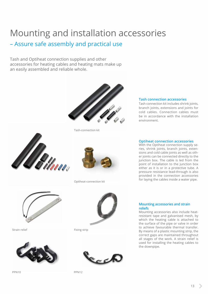
Mounting accessories and strain reliefsMounting accessories also include heat-resistant tape and galvanised mesh, by which the heating cable is attached to the surface of the pipe or valve in order to achieve favourable thermal transfer. By means of a plastic mounting strip, the correct gaps are maintained throughout all stages of the work. A strain relief is used for installing the heating cables to the downpipe.
Tash and Optiheat connection supplies and other accessories for heating cables and heating mats make up an easily assembled and reliable whole.
Tash connection accessoriesTash connection kit includes shrink joints, branch joints, extensions and joints for cold cables. Connection cables must be in accordance with the installation environment.
Optiheat connection accessoriesWith the Optiheat connection supply se-ries, shrink joints, branch joints, exten-sions and cold cable joints as well as oth-er joints can be connected directly to the junction box. The cable is led from the point of installation to the junction box either as it is or in a protective tube. A pressure resistance lead-through is also provided in the connection accessories for laying the cables inside a water pipe.
PPN10 PPN12
Fixing strip
Tash-connection kit
Optiheat-connection kit
Strain relief
13

Water Pipe Frost Protection Accessories
Plastic pipe LT20 Fibreglass tape * *
EFPLP1 Connection kit *
EFPLP2 Connection kit *
Plastic, installed in pipeEFPLV1 Pressure resist-ance lead-through
* *
EFPLP1 Connection kit *
EFPLP2 Connection kit *
Metal pipe LT20 Fibreglass tape * * * *
SV10 Galvanised mesh * * *
ALU50 Aluminum tape * * *
EFPLP1 Connection kit * *
EFPLP2 Connection kit * *
EFPLP4 Connection kit *
Drain Pipe Frost Protection
Plastic pipe LT20 Fibreglass tape * *
SV10 Galvanised mesh * *
EFPLP1 Connection kit *
EFPLP2 Connection kit *
Metal pipe LT20 Fibreglass tape * * * *
SV10 Galvanised mesh * * * *
ALU50 Aluminum tape * * * *
EFPLP1 Connection kit * *
EFPLP2 Connection kit * *
EFPLP4 Connection kit *
OPT
IHEA
T 20
/40
TASH
PLU
G’N
HEA
T
OPT
IHEA
T 10
Selection of accessories
This table will provide help in selecting heating cable accessories. The selection of right accessories will ensure the proper functioning of frost protection solutions in given conditions.
14
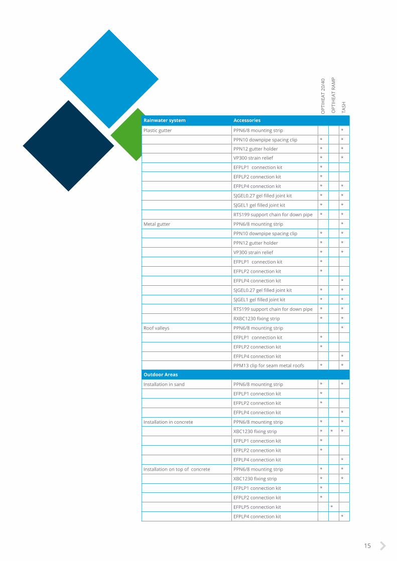
Rainwater system Accessories
Plastic gutter PPN6/8 mounting strip *
PPN10 downpipe spacing clip * *
PPN12 gutter holder * *
VP300 strain relief * *
EFPLP1 connection kit *
EFPLP2 connection kit *
EFPLP4 connection kit * *
SJGEL0.27 gel filled joint kit * *
SJGEL1 gel filled joint kit * *
RTS199 support chain for down pipe * *
Metal gutter PPN6/8 mounting strip *
PPN10 downpipe spacing clip * *
PPN12 gutter holder * *
VP300 strain relief * *
EFPLP1 connection kit *
EFPLP2 connection kit *
EFPLP4 connection kit *
SJGEL0.27 gel filled joint kit * *
SJGEL1 gel filled joint kit * *
RTS199 support chain for down pipe * *
RXBC1230 fixing strip * *
Roof valleys PPN6/8 mounting strip *
EFPLP1 connection kit *
EFPLP2 connection kit *
EFPLP4 connection kit *
PPM13 clip for seam metal roofs * *
Outdoor Areas
Installation in sand PPN6/8 mounting strip * *
EFPLP1 connection kit *
EFPLP2 connection kit *
EFPLP4 connection kit *
Installation in concrete PPN6/8 mounting strip * *
XBC1230 fixing strip * * *
EFPLP1 connection kit *
EFPLP2 connection kit *
EFPLP4 connection kit *
Installation on top of concrete PPN6/8 mounting strip * *
XBC1230 fixing strip * *
EFPLP1 connection kit *
EFPLP2 connection kit *
EFPLP5 connection kit *
EFPLP4 connection kit *
OPT
IHEA
T 20
/40
OPT
IHEA
T RA
MP
TASH
15

Quick and effectivefrost protection

Electric frost protectionSimple structural applications
The electrical control of frost protection is quick and effective. This energy-efficient solution requires the correct power sizing and heating control in accordance with requirements.
Frost protection for water and drain pipesFrost protection control prevents frozen pipes from causing water damage. Primary place for the heating cable is on the surface of a water pipe, but a cable may also be installed inside the water pipe as required.
Frost protection for rainwater systemsBy means of frost protection control over rainwater systems, water-freezing in connection with temperature changes in rainwater gutters and roof structures is prevented. Heavy ice masses damage structures and can be dangerous for those walking in the vicinity. The melt waters route must be looked after all the way to the rainwater drains.
Frost protection for ramps and other demanding areasOptiheat RAMP is intended for demanding frost-protection applications, such as vehicle ramps, helipads, and other frost-protection needs requiring high power per meter. In addition to ice-free maintenance, run-off route planning for melt waters must also be kept in mind.
Frost protection for outdoor areas By using frost protection for outdoor area, the pavements of a property are kept safe to walk on. Planning begins from the clarification of installation site conditions and the structure of the area to be heated. In addition to ice-free maintenance, run-off route planning for melt waters must also be kept in mind.
17

Sizing frost protection of pipework
In planning the heating ofpipes, we proceed as follows:1. Thermal losses in the pipe
are determined (table or by calculation)
2. Heating power is dimensioned: 1.3–1.5 x thermal loss
3. L ength of the heating cable is calculated.
4. On the basis of the cable tables, the appropriate specific resistance of the cable is specified.
5. The type of cable is chosen that achieves sufficient installation output.
6. Check that the total output is adequat and that the highest permitted metric output is not exceeded.
7. If the power per meter output exceeds what is permitted, the length of the heating cable is extended with several cable loops heating the pipe.
The thermal efficiency and cable type for the piping system are determined in accordance with material, size and thermal losses.
The following should be noted with Tash series-resitant cables:• highest permitted power per
meter output (plastic pipe 10 W/m, metal pipe 20 W/m)
• the cable does not criss-cross• the heating cable is generally
installed along the pipe• the cabling is always installed as
loops, two heating cables go to the pipe
Water pipe material Maximum cable power/m output Heating cable
Plastic 10Optiheat 10Plug´n HeatTash
Metal 20
Optiheat 10Optiheat 20/40Plug´n HeatTash
Plastic/metal, heating cable inside pipe
10 Plug´n Heat
Optiheat 10 heating cable for heating plastic and metal pipes. Take sensor position into account. An aluminium tape divides heat more evenly and a galvanised mesh is also used here. The pipe must be insulated. (PICTURE PROVIDED FOR GUIDANCE ONLY)
18

InsulationInsulation is the factor that affect heat loss most. Properly covered pipe with thermal insulation to retain heat losses. You need less heating power per meter if you use more insulation.
Instructions for reading the table
Thermal loss table for pipeAn uncertainty factor of 1.3 to 1.5 should be applied to the values in the table. The thermalloss table for pipes is used for determining how much power per meter of pipe is required for keeping the pipe water unfrozen.
1. The first column shows the outer pipe diameter.
2. The second column gives the insulation thickness.3. In the next columns, the values 20 °C to 60 °C refer
to the temperature difference between the pipe and environment. When you want to keep the pipe unfrozen in an environment where the temperature can get as low as –30 °C, you should select the 40 °C column for perusal. With regard to dimensioning, the insulation’s thermal conductivity is 0.035 W/m2. (Mineral wool: +10 °C.)
N.B. Holder rings (brackets) and valves have not been taken into consideration regarding sizing.
TsPipe
Insulation
Tu
du
ds
Thermal loss table for pipe(W/meter of pipe)
OUTER DIAMETERof PIPE Ø/mm
INSULATIONTHICKNESS mm 20 ˚c 30 ˚c 40 ˚c 50 ˚c 60 ˚c
14 20 3.3 4.9 6.5 8.1 9.830 2.6 4.0 5.3 6.6 7.940 2.3 3.5 4.6 5.8 6.950 2.1 3.1 4.2 5.2 6.3
21 20 4.1 6.2 8.2 10.3 12.430 3.3 4.9 6.5 8.1 9.840 2.8 4.2 5.6 7.0 8.450 2.5 3.8 5.0 6.3 7.5
27 20 4.8 7.3 9.7 12.1 14.530 3.8 5.6 7.5 9.4 11.340 3.2 4.8 6.4 8.0 9.650 2.8 4.3 5.7 7.1 8.580 2.3 3.4 4.5 5.7 6.8
34 20 5.7 8.5 11.3 14.1 17.030 4.3 6.5 8.6 10.8 13.040 3.6 5.5 7.3 9.1 10.950 3.2 4.8 6.4 8.0 9.680 2.5 3.8 5.1 6.3 7.6
42 30 5.0 7.4 9.9 12.4 14.940 4.1 6.2 8.2 10.3 12.450 3.6 5.4 7.2 9.0 10.880 2.8 4.2 5.6 7.0 8.4
48 30 5.4 8.1 10.8 13.6 16.340 4.5 6.7 9.0 11.2 13.550 3.9 5.9 7.8 9.8 11.780 3.0 4.5 6.0 7.5 9.0
60 30 6.3 9.5 12.7 15.9 19.040 5.2 7.8 10.4 13.0 15.650 4.5 6.7 9.0 11.2 13.580 3.4 5.1 6.8 8.5 10.2
76 30 7.6 11.3 15.1 18.9 22.740 6.1 9.2 12.2 15.3 18.350 5.2 7.9 10.5 13.1 15.780 3.9 5.8 7.8 9.7 11.6100 3.4 5.1 6.8 8.5 10.2
89 30 8.5 12.8 17.1 21.3 25.640 6.9 10.3 13.7 17.1 20.650 5.8 8.8 11.7 14.6 17.580 4.3 6.4 8.6 10.7 12.8100 3.7 5.6 7.5 9.3 11.2
114 30 10.4 15.6 20.8 26.0 31.240 8.3 12.4 16.5 20.7 24.850 7.0 10.5 14.0 17.5 21.080 5.0 7.5 10.0 12.5 15.0100 4.3 6.5 8.7 10.9 13.0
168 40 11.3 16.9 22.6 28.2 33.950 9.4 14.1 18.8 23.5 28.380 6.6 9.9 13.1 16.4 19.7100 5.6 8.4 11.2 14.0 16.8120 5.0 7.4 9.9 12.4 14.9
219 40 14.1 21.2 28.3 35.3 42.450 11.7 17.5 23.4 29.2 35.180 8.0 12.0 16.0 20.0 24.1100 6.8 10.2 13.6 16.9 20.3120 5.9 8.9 11.9 14.9 17.8
273 40 17.1 25.7 34.2 42.8 51.350 14.1 21.1 28.2 35.2 42.380 9.5 14.3 19.1 23.8 28.6100 8.0 12.0 16.0 20.0 24.0120 7.0 10.5 13.9 17.4 20.9
Temperature difference TS – TU
ExampleA plastic pipe’s outer diameter is 48 mm, insulation thickness 50 mm, and temperature difference 35 °C. This translates into a heat loss of 7.8 W/m. Here, 1.4 is selected as the uncertainty factor, for a design power of 7.8 x 1.4 = 10.92 W/m. Since the maximum metric load on the surface of the plastic pipe is 10 W/m, Optiheat 10 is selected as the heating cable. Same issue can be also calculated:
Thermal loss of a pipe
Φ= 2 π λinsulation * (Ts – Tu) ln du ds Φ Thermal loss of a pipe (W)λinsulation Thermal conductivity of insulation (W/mK)du Pipe overall diameter with insulation (m)ds Pipe diameter (m)Ts Inside temperature in pipe (°C)Tu Outside temperature (°C)
19

Heating cable external to the pipeThe heating cable is installed horizontally next to the pipe (5 o’clock). When two heating cables are used, the cables are installed on the bottom edge (at 5 and 7 o’clock). The heating cable is attached to the pipe so that the cable is fixed closely to the surface of the pipe. The thermostat sensor controlling the heating is placed on the opposite side from the heating cable.
The following may be used for mounting:• heat-resistant fiberglass tape (LT20)• heat-compensating aluminium tape (ALU50) applied along the pipe• galvanised mesh (SV10)
Heating cable inside the pipeThe heating cabling inside the water pipe is conveyed to the pipe by a pressure resistant lead-through (EFPLV1). In the installation the cable is horizontal at the lower edge of the pipe. The thermostat sensor is mounted on top of the pipe.
Installation for pipework
One heating cableThe sensor is on the opposite side. (PICTURE PROVIDED FOR GUIDANCE ONLY )
Two heating cables Are required for pipes with a large diameter (over 50 mm). The sensor is attached to the upper surface of the pipe. (PICTURE PROVIDED FOR GUIDANCE ONLY )
Heating cable inside the pipeAre required for pipes with a large diameter (over 50 mm). The sensor is attached to the upper surface of the pipe. (PICTURE PROVIDED FOR GUIDANCE ONLY)
EFPLV1 lead-inLead-in for Optiheat 10 cable for water pipes.
20

Extendable, max. 25 m, 2 x 1,5 mm2
NTC sensor 4 m
NTC sensor47 k Ω (@25 C˚)
Heating cable
Max. 16 A
Max. 3600 W
I F = 30 m A
NTC sensor
T / C R /k Ω 0 1565 12110 9415 7420 5925 47
A pipeline frost protection system must always be controlled with an operating switch. A thermostat is recommended to be used to activate heating only when necessary, thus avoiding the unnecessary waste of energy. Without a thermostat control the self-regulating cable’s lifetime is shorter because it is activate all the time.
Ready-made Plug’n Heat cables can be directly connected to the socket outlet when heating is required.
Heating implemented with series-resistant cables (Tash) is always controlled with a thermostat. The thermostat sensor is mounted on top of the pipe.
Controlling pipeline By using ECO500 thermostat
21

Frost protection of water pipes
Heating cables can be used for preventing water pipes that are vital to a property from being frozen, and for preventing water damage. Near outer walls, the impact of cold bridges is prevented by heating and insulating water pipes and their shutoff valves.
The heating power and cable type of pipes are determined on the basis of the pipe material and size as well as thermal loss. Pipe size, installation environment, and insulation are the factors that affect heat loss most.
Heat loss calculation is based on the principle that the insulation remains dry and does not have cracks etc.. A tolerance factor of 1.3–1.5 x the heat loss value is used in the design (see table on page 19).
Self-regulating cables (Optiheat) and series-resistant cables (Tash) are suitable for frost protection of pipes. The maximum metric outputs of heating cables can be found in the table on page 18.
The heating cable is usually installed on the pipe surface, but it can also be installed inside pipes if so required. In these cases, a heating cable, tested for compliance with regulations for operations involving foodstuffs and designed for drinking-water pipes, must be used.
Near the outer wall, the creation of cold bridges is prevented by heating and insulating the water pipe, water gauge, and shutoff valve. (PICTURE PROVIDED FOR GUIDANCE ONLY )
The heating cable in a water pipe is inserted into the pipe via a pressure resistant lead-through (EFPLV1). (PICTURE PROVIDED FOR GUIDANCE ONLY )
22

Plug’n Heat
Frost protection of valves(also applicable for brackets)
Factory made Plug’n Heat cables are equipped with a plug. The cables have polyethylene sheaths and they’re tested for compliance with regulations on use with foodstuffs, meaning that they can be installed in drinking-water pipes too. The heating cables are directly inserted into the pipes via a pressure resistent lead-through EFPLV1. Thanks to the plug, the cables can be plugged directly into a socket outlet, for use whenever heating is required. Additional protection for heating cables must always be provided by means of a residual-current device that is either in the distribution board or integrated with the socket outlet.
The pipe’s normal frost protection sizing is sufficient. At the valve, an extra cable loop is made in order to offset heat loss through the valve shaft to outside the insulation. The valve and pipe must be insulated. The extra cable loop also provides flexibility for cases in which the valve has to be replaced.
23

+
NL
DC LO
DC ON
ECO920
LN
ECOA907bl
ack
brow
nbl
ue
12
13
>25 mm
230 V/AC
+ -5 6 7 8 9
10 1112 13 14
1 2 3 4
5 6
blac
k
whi
te
Rain water gutter
Horizontal / vertical < 150 20–60
Rain water gutter
Horizontal > 150 200
Roof valley > 150 200
Gut
ter
wid
th
Inst
alla
tion
outp
utpe
r su
rfac
e to
be h
eate
d
Inst
a lla
tio n
out
put
per
e.g.
gut
ter
met
er
W/m2mm W/m
Rain water system Sizing and Designing
Installation
For narrow gutters, the design and power for keeping a rainwater system ice-free is sufficient if it is approx. 20 W/m, i.e., one Tash cable per gutter is adequate. Greater heating power requires installation of more than one heating cable in the gutter.
A rain water system consists of a heating cable as well as mounting accessories and control device.
A cable is fastened to the top ends of the vertical gutters with cable clamps. In long vertical gutters (>10m), support cable wire is also used. Cable clamps are mounted, if required, on the horizontal gutters.
Optiheat cables can live freely along the gutters but they’re recommended to set to the gutters.
Tash series-resistant cables are fixed to the gutters. Plastic mounting strips, plastic-coated cable clamps or cable wire supports combinations are used on horizontal sections.
Rain water wells on the roof must be protected from freezing in order to prevent ice damage to the wells and roof structures. In rain water well heating applications, the cable should extend for quite a distance into a warm area, since otherwise downspouts cool across a fairly long distance downwards. Roof wells usually include a factory-installed heating cable to which the supply voltage is connected.
In large-scale applications is recom-mended to use the TASH cable and a temperature control system. Using self-regulating cables the control sys-tem shall be to keep the starting peaks lower and to ensure the long life time of the cables.
Heating cable Thermostat Sensor Connectionaccessories
Mountingaccessories
Optiheat 20/40
ECO900ECOA903 + ECOA904 EFPLP1
EFPLP2EFPLP3
VP300PPN13 RXBC1230
ECO910
ECO920 ECOA907
TASH
ECO900ECOA903 + ECOA904
EFPLP4
VP300PPN8PPN6PPN13XBC1230
ECO910
ECO920 ECOA907
NTC sensorT / C R /k Ω 0 1565 12110 9415 7420 5925 47
NTC sensorT / C R /k Ω 0 32.610 1815 14.720 12.125 10.0
24

Junction box Strain relief
The frost protection cable and the sensors are attached by using a PPN6/8 mounting strip. The top end of the downpipe is equipped with a VP300 strain relief unit. In long downpipes (>10 m long) a wire is needed for holding the weight of the cable. The rain water system must be kept free of leaves. (PICTURE PROVIDED FOR GUIDANCE ONLY)
25

-30 -20 -10 0 10 20 30 40 °C
OPTIHEAT 20/40OPTIHEAT 10
403836343230282624222018161412108642
W/m
Frost protection of rainwater systems in a detached house Applying Optiheat heating cabling
Maximum installation lengths
Design and installationof frost protection forrainwater guttersThe metric output of the Optiheat 20/40 heating cable is 28W/m–24W/m in an environment with a temperature of –5 °C…+5 °C. In ice water, its metric power output is around 40 W/m.
One or more heating cables are installed in the horizontal sections and downpipe of the rainwater gutter in order to achieve the desired installation output. In the southernmost parts of Finland, one cable is sufficient for narrow gutters; more cables are required in other parts of Finland and for wider gutters (i.e., those with a diameter of over 150 mm).
The heating cable is installed as a loop in horizontal gutters, with the cable ending at the bottom end of the downpipe. Optiheat cables can be left free or inserted into an aluminium pipe. The cable is mounted using a strain relief (VP300) at the top end of a downpipe and, if required, a plastic-coated cable clamp at thebottom end.
Heating cables are connected to junction boxes. If required, a cold lead that is connected to the heating cable by a cable joint e.g. connection kit EFPLP2 can be used. The termination kit has to be used in the other end of the cable.
In Optiheat cables, the switching current is around 1.5 x the operating current. Since around 60 meters of heating cable in ice water can be installed in a group protected with a 10 A circuit breaker, heating is connected to a single group. The heating is controlled via an ECO910, ECO920 or ECO900 thermostat. See the wiring diagram on pages 24 and 29.
Maximum cable installation lengths with certain switching temperatures at which the cable’s surface temperature is still the same as the ambient temperature.
Alteration of Optiheat 10 and Optiheat 20/40 heating cables’ power output as the ambient temperature changes.
Optiheat heating cables’ temperature/power output curves and maximum installation lengths
Optiheat 10 10 A 16 A 32 A
On pipe surface +10 °C 74 m 89 m -
On pipe surface ±0 °C 61 m 89 m -
On pipe surface –30 °C 61m 89 m -
Optiheat 20/40
On pipe surface +10 °C 68 m 109 m 129 m
On pipe surface ±0 °C 57 m 92 m 119 m
On pipe surface –10 °C 50 m 79 m 111 m
On pipe surface –20 °C 44 m 70 m 104 m
Optiheat RAMP
On concrete -10 °C 18 m 28 m 55 m
26

3600 2700
38003600
L1
L1
L3L3sensor
5 x 1,5L1L1 L2L2
31
3536
32
38
37
33 34
2 X 1, 5
37
33
34
Frost protection of roof valleysWith heating that has been installed in the roof valleys, ice that has possibly accumulated in the eaves of the roof can be melted. As installation output, approx. 200 W/m2 is used, which is approx. 60 W/m in the example site. The amount of installed cable to roof valley is 16m of Optiheat 20/40 cable (point 37 in picture below). Cable length is compared to the Optiheat 20/40 cable’s maximum installation length for creation of an installation.
Example calculation:Roof Valley: 5,2m x 0,3m = 1,6m2
Needed heating power: 1,6m2 x 200W/m2 = 320W
Lenght of heating cable: 320W / 20W/m = 16mIntallation space: 6m2 / 16m = 0,1m = 10cm
Example: Residential house
Output/gutter lengthW/m
Optiheat 20/40,total number of cables
Horizontal gutter 40 2
Vertical gutter 20 1
Roof valley 60 3
Pos. Horizontal gutter, m Vertical gutter, m Length of heating cable
31 3,6 5,8 (2 x 3,6 + 5,8) = 13,0
32 2,7 5,8 (2 x 2,7 + 5,8) = 11,2
33 3,6 5,8 (2 x 3,6 + 5,8) = 13,0
34 3,8 5,8 (2 x 3,8 + 5,8) = 13,4
Total 50,6
Pos. Roof VALLEY length, m Roof VALLEY width, m Lämmityskaapelin pituus, m
35 5,2 0,3 320W / 20W/m = 16m
36 5,2 0,3 320W / 20W/m = 16m
37 5,2 0,3 320W / 20W/m = 16m
38 5,2 0,3 320W / 20W/m = 16m
Total 64
27

25 m25 m25 m25 m
A B
C D
A
A rainwater system in an industrial hallUsing Tash series-resistant cabling
If the design power in the gutter is 20–60 W/m, 30 W/m is selected. The installation output of the Tash cable can be maximum 20 W/m in a metal gutter, so it is installed as loops, approx. 15 W/m.
ExampleRain water gutter length (A + B):4 x 25 m + 2 x 5.8 m + 3 x 6.7 m≈ 132 m
Heating cable (A + B):length 2 x 132 m = 264 m
Heating output P1= 15 W/m x 264 m = 3 960 W
To be connected either to the principalvoltage or distributed to two links.
Total output(A + B + C + D) = 7 920 W
Heating is connected toa 3 x16 A group.
Control in the example is done with ECO900+ECOA903+ECOA904 but it can be also done with ECO920 and ECOA907.
2 X 1.5
5 X 1.5
5 X 2.5P = 1 099 W
TASH 0,65 Ω/m/74 mR = 48 Ω
Downpipe height 5.8 m
P = 2 784 WTASH 0,1 Ω/m/190 m
R = 19 ΩDownpipe height 6.7 m
P = 1 099 WTASH 0.65 Ω/m/74 m
R = 48 ΩDownpipe height 5.8 m
P = 2 784WTASH 0,1 Ω/m/190 m
R = 19 ΩDownpipe height 6.7 m
ECOA904ECOA903
L3 L1
L3 L2
B
C D
5.8
m
6.7
m
5.8
m
6.7
m
28

X2 X3
X1
20 21
230 V ACL1NPE
10 11 12 13 14 15 16 17 18 19 20 21
1 2 3 4 5 6 7 8 9
ALA
RM
LOA
D
82 kΩ / ECOA904
ECOA903
ECOA904
10 11 12 13 14 15 16 17 18 19 20 21
-20 T 50 NC
230 Vú ALARM230 V / 2 A
HEATER230 V / 16 A
white grey green yellow brown blue
ECOA901/ECOA903
ECOA902 ECOA904
ECOA904 or 82 kΩblue brown
1 2 3 4 5 6 7 8 9NC
brownwhite grey yellow brown
whi
te
grey
gree
n
yello
w
brow
n
blue
brow
n
ECO900
82 kΩ
82 kΩ
+
NL
DC LO
DC ON
ECO920
LN
ECOA907
blac
k
brow
nbl
ue
12
13
>25 mm
230 V/AC
+ -5 6 7 8 9
10 1112 13 14
1 2 3 4
5 6
blac
k
whi
te
EXAMPLE LOOP A (=LOOP C) LOOP B (=LOOP D)
Gutter length + downpipe length 25 m + 2 x 5.8 m ≈ 37 m 3 x 25 + 3 x 6.7 m ≈ 95 m
Required power output 30 W/m 1 110 W 2 850 W
Heating cable length 2 x 37 m = 74 m 2 x 95 m = 190 m
Heating cable resistance (230V)2 / (1 110 W x 74 m) ≈ 0,64 Ω/m (230V)2 / (2 850 W x 190 m) ≈0,1 Ω/m
Selecting heating cable Tash 0,65 Ω/m Tash 0.1 Ω/m
Installation power 1 099 W 2 784 W
Total power (A+B+C+D) 2 x (1 099 W + 2 784 W) = 7 766 W
29

10 Ω/m 6 Ω/m
W/m 230 V length/m
Output/W
400 V length/m
Output/W
6 30 176 52 3088 26 203 45 35610 23 230 40 40012 21 252 37 43214 19 278 34 47116 18 294 32 50018 17 311 30 53320 16 331 28 57122 16 331 27 59324 15 353 26 61526 14 378 25 64028 14 378 24 66730 13 407 23 696
W/m 230 V length/m
Output/W
400 V length/m
Output/W
6 38 232 67 3988 33 267 58 46010 30 294 52 51312 27 327 47 56714 25 353 44 60616 23 383 41 65018 22 401 38 70220 21 420 37 72122 20 441 35 76224 19 464 33 80826 18 490 32 83328 18 490 31 86030 17 519 30 889
Outdoor areas Sizing and planning
The power per square meter used in a frost protection solution for an outdoor area depends on factors including the purpose of use and structures.
Installation site conditions and the structure of the areas to be heated are always the starting points in the design and implementation of frost protection. The melt water route must be designed in co-operation with other designers in order to prevent melt water from caus-ing problems elsewhere on the site.
The heating cable is selected on the ba-sis of the area and the heating output required. The cables used are self-regu-lating (Optiheat) and series-resistant ca-bles (Tash) as well as ready-made mats.
The process of designinga frost protection system:• select the cable type• select the suitable power per meter
output or specific resistance• determine the installation spacing• select the control system
Tash 400v connection
Installation Site Installation Power, W/m2
Pavements (protected from wind) 150–200
Pavements (unprotected) 200–250
Outdoor steps and areas in front of doors
200–300
Parking areas and roadways 250–300
Loading areas (insulated) 250–300
Loading areas (uninsulated) 300–400
Heating Cable Type Characteristic Use
Self-regulating cable (Optiheat)Easy to design and install.High cable cost
Small areas. Concrete structures, steps, etc.
Frost protection mat (ULLA300)Quick to install. Stable instal-lation power. Only one power per square meter output
Suited to areas of all sizes.Concrete and sand
Series-resistant cable (Tash)Low cable cost.Requires careful planning
Versatile areas.Large areas. Concrete and sand.
Tash cable tablesThe tables show cable-specific maximum installation lengths with certain metric loads. The tables also indicate outputs in relation to lengths. The values are measured with both 230 V and 400 V switching voltage.
30

3 Ω/m 1.5 Ω/m 1 Ω/m
0.82 Ω/m 0.65 Ω/m 0.45 Ω/m
W/m 230 V length/m
Output/W
400 V length/m
Output/W
6 54 327 94 5678 47 375 82 65010 42 420 73 73112 38 464 67 79614 35 504 62 86016 33 534 58 92018 31 569 54 98820 30 588 52 102622 28 630 49 108824 27 653 47 113526 26 678 45 118528 25 705 44 121230 24 735 42 1270
W/m 230 V length/m
Output/W
400 V length/m
Output/W
6 77 458 133 8028 66 534 115 92810 59 598 103 103612 54 653 94 113514 50 705 87 122616 47 750 82 130118 44 802 77 138520 42 840 73 146122 40 882 70 152424 38 928 67 159226 37 953 64 166728 35 1008 62 172030 34 1037 60 1778
W/m 230 V length/m
Output/W
400 V length/m
Output/W
6 94 563 163 9828 81 653 141 113510 73 725 126 127012 66 802 115 139114 61 867 107 149516 58 912 100 160018 54 980 94 170220 51 1037 89 179822 49 1080 85 188224 47 1126 82 195126 45 1176 78 205128 43 1230 76 210530 42 1260 73 2192
W/m 230 V length/m
Output/W
400 V length/m
Output/W
6 104 620 180 10848 90 717 156 125110 80 806 140 139412 73 884 128 152414 68 949 118 165416 63 1024 110 177418 60 1075 104 187620 57 1132 99 197122 54 1195 94 207624 52 1241 90 216826 50 1290 87 224328 48 1344 83 235130 46 1402 81 2409
W/m 230 V length/m
Output/W
400 V length/m
Output/W
6 117 696 203 12138 101 806 176 139910 90 904 157 156812 83 981 143 172114 76 1071 133 185116 71 1146 124 198518 67 1215 117 210420 64 1272 111 221822 61 1334 106 232224 58 1403 101 243726 56 1453 97 253828 54 1507 94 261930 52 1565 91 2705
W/m 230 V length/m
Output/W
400 V length/m
Output/W
6 140 840 243 14638 121 972 211 168510 108 1088 189 188112 99 1187 172 206714 92 1278 159 223616 86 1367 149 238618 81 1451 141 252220 77 1527 133 267322 73 1610 127 280024 70 1679 122 291426 67 1755 117 303928 65 1809 113 314730 63 1866 109 3262
W/m 230 V length/m
Output/W
400 V length/m
Output/W
6 166 996 289 17308 144 1148 250 200010 129 1281 219 228312 117 1413 204 245114 109 1517 189 264616 102 1621 177 282518 96 1722 167 299420 91 1817 158 316522 87 1900 151 331124 83 1992 144 347226 80 2066 139 359728 77 2147 124 375930 74 2234 129 3876
W/m 230 V length/m
Output/W
400 V length/m
Output/W
6 205 1229 356 21408 177 1423 309 246610 159 1584 276 276112 145 1737 252 302314 124 1880 233 327016 125 2015 218 349518 118 2135 206 369920 112 2249 195 390722 107 2354 186 409624 102 2470 178 428026 98 2570 171 445628 95 2652 165 461830 92 2738 159 4792
W/m 230 V length/m
Output/W
400 V length/m
Output/W
6 228 1365 396 23778 197 1580 343 274410 176 1768 307 306612 161 1933 280 336114 149 2088 259 363416 139 2239 243 387318 131 2375 229 411020 125 2489 217 433722 119 2615 207 454724 114 2730 198 475326 109 2855 190 495428 105 2964 183 514330 102 3151 177 5317
W/m 230 V length/m
Output/W
400 V length/m
Output/W
6 297 1781 516 31018 257 2058 447 357910 230 2300 400 400012 210 2519 365 438414 194 2727 338 473416 182 2907 316 506318 171 3094 298 536920 163 3245 283 565422 155 3413 270 592624 149 3550 258 620226 143 3699 248 645228 138 3833 239 669530 133 3977 231 6926
W/m 230 V length/m
Output/W
400 V length/m
Output/W
6 420 2519 730 43848 364 2907 632 506310 325 3255 566 565412 297 3562 516 6202
0.21 Ω/m0.32 Ω/m 0.17 Ω/m
0.05 Ω/m0.1 Ω/m
31

Vehicle access ramps
If the traffic using the vehicle access ramp is light, the frost protection control cables are installed on the ramp only at the location of the wheels. When heavy traffic uses the ramp or it is steep, the frost protection heating cables are installed throughout the entire area. If the area has slopes, the route for melting water must also be protected from freezing.
Example 1 Light vehicle access ramp frost protection can be maintained with an ULLA300 frost protection mat (300 W/m2). In this case, 10 meters long and 4 meters wide, two ULLA300 mats (300.10) are chosen at the location of the wheels, producing a total frost protection output of 6 kW. Heating is regulated either with the ECO900 control system or the ECO910 frost protection control thermostat.
Example 2 An alternative is to install Tash cabling to a strip 0.5 meters wide at the location of the wheels. The cabling is installed into the concrete with maximum load of the cable at 30 W/m. The heating cable must not be installed across the movement joint.
Total output forms 3 kW (1 500 W/ strip). A suitable Tash cable can be chosen from the sizing tables. The load output is 1 500 W and maximum load 30 W/m, i.e., cable type Tash 0.65 Ω is chosen.
Since the total output is rather small (3.1 kW), an ECO 910 frost protection control thermostat is selected for control purposes. The two sensors in the thermostat enable both ground and air temperature measurement.
Frost protection of entrance areaThe self-regulating cable is selected according to the size of the area and the required output. The metric output of the Optiheat 20/40 cable varies with the temperature.
Outdoor heating is usually required with an outdoor temperature of –5 °C to 5 °C. In these cases, the cable’s metric output (P metric) is around 28W/m–24W/m.
The required cable length is calculated on the basis of the cable’s metric output l cable = P length / P metric
The cable installation spacing is calculated by dividing the installation area (A installation) by the heating cable length (l cable). d = A installation / l cable
Heating is controlled by ECO910, ECO920 or ECO900 frost protection thermostat installed in the panel board or by an operating switch.
With light traffic, it suffices to install frost protection cables only on the wheel routes on the ramp (installation in concrete). In the inclined area, freezing of melt water must be prevented also. (PICTURE PROVIDED FOR GUIDANCE ONLY )
Heavy traffic requires frost protection cables to be installed throughout the ramp area (installation in concrete). In the inclined area, freezing of melt water must be prevented also. (PICTURE PROVIDED FOR GUIDANCE ONLY )
Example 1.
Example 2.
32

1
2
3
4
5
6
7
8
1
2
3
4
5
6
7
Designing and installing of loading area
Example 1:The loading area is 24 m long and 4 m wide 300 W/m2 is used as the installa-tion output, since the underlay of the installation site is insulated. A 300 m2 ULLA300 frost protection mat is select-ed, with six mats chosen for the area, four for the large turnaround area and two underneath the wheels.
The total frost protection output comes to 6 x 3.6 kW = 21.6 kW. Frost protection is controlled by means of the ECO900 control system. The ECOA901 snow and ice sensor is installed outside the heated area, with the temperature and humidity sensor, ECOA902, installed in the heated area. Frost protection mats are installed in the sand or concrete lo-
cated underneath the heated layers (in this case, the asphalt) surface layer.
Heating cable is installed around the rainwater well in order to prevent melt water from freezing, and around the drain output pipe below the ground frost level.
Example 2:Frost protection of the inclined area, de-signed for heavy traffic, is implemented with Tash cables throughout the area. There is no insulation underneath the sand, yielding a 400 m2 design power. The total frost protection output is 24 m x 4 m x 400 m2 = 38.4 kW, controlled by the ECO900 control system.
A Tash cable with a max. 25 W/m load output is selected from the tables. The Tash 0.45 cable fulfils these require-ments with a 400 V voltage. In total, 12 cables are required (supply of 16 A). The length is 122 m and output 2 921 W. Cable connections are shown on page 30.
The total output is 12 x 2 921 W = 35.05 kW, the output per square meter 35.05 W/96 m2 = 365 m2, and the installation spacing 8 m2/122 m = 6.5 cm. The cables are installed in the sand or concrete that is under the heated layer (usually tile or asphalt).
Installation examplesInstallation of an ULLA300 frost protection mat in the sand underneath the asphalt. There is in-sulation underneath the sand.
1. Soil / gravel2. Insulation3. Sand or concrete4. ULLA300 frost protection mat5. Snow and ice sensor6. Temperature and humidity sensor7. Asphalt(PICTURE PROVIDED FOR GUIDANCE ONLY )
Installation of a Tash heating cable in concrete with an expansion joint. No insulation underne-ath the concrete.
1. Soil / gravel2. Sand3. Concrete4. Reinforcement mesh5. Expansion joint6. Tash heating cable7. Snow and ice sensor8. Temperature and humidity sensor(PICTURE PROVIDED FOR GUIDANCE ONLY )
33

1
2
3
4
5
1
2
3
4
5
Installation in outdoor areas
Heating cables are usually installed in the sand or concrete (N.B. not in asphalt!) underneath the heated layer’s surface layer. Optimal frost protection efficiency is achieved by insulating the frost-protected area from underneath.
The heating cable is installed at a minimum depth of 5 cm in order to prevent, for instance, traffic from damaging it. The heating cable may not be installed across movement joints. Installation areas are designed in such a manner that only connecting leads (cold leads) cross movement joints.
Installation in sandIn a paved or asphalted area, the heating cable is installed in the installation sand underneath the surface layer. The grain size of installationsand is 0.063 to 2 mm. There should be around 3 cm of sand between the insulation and the heating cable. Either an ULLA300 frost protection mat or a series-resistant Tash cable is used as the heating cable.
A thin layer of sand is spread over the installed cable and manually leveled using a long-handled leveler with an edge that is either rounded or protected with a strip of felt. The cable’s outer sheath must not be damaged and the cable must not come loose from its fastenings. A surface layer is laid over the sand, for example tiles, concrete or asphalt.
Installation in concreteThe heating cable is loosely attached to the reinforcement mesh (with, for example, a cable tie) without damaging the cable’s outer sheath. In order to aid in any later troubleshooting and repairs, the cable is laid on top of the reinforcement mesh.
1. Insulation2. Sand3. ULLA300 frost protection mat4. Sensor5. Pavement, asphalt, or concrete(PICTURE PROVIDED FOR GUIDANCE ONLY )
1. Insulation2. Heating cable3. Reinforcement mesh4. Concrete5. Sensor(PICTURE PROVIDED FOR GUIDANCE ONLY )
34

1
2
3
4
5
6
7
Heating of cold room floor
Cold rooms and refrigerated warehouses where the temperature is continuously below –20 °C cool the surrounding floor even when there is good floor insulation. Due to this, all structures connected to the ground/ soil, such as foundations and floors, conduct heat away from the ground, causing the ground/soil to freeze. Frost in the ground will then cause damage.
An installed power of around 15–20 W/m2 is sufficient for the floor structure of a cold room, with a maximum installa-tion spacing of 50 cm.
The amount of thermal loss directed downwards is affected by the U-value of the floor structure, desired ground temperature and the temperature of the cold room.
ExampleCold room indoor temperature –25 °CGround temperature +4 °CFloor structure U value 0,1 W/m2 °C
Thermal loss of the floor:Ф/A = 29 °C x 0,1 W/m2 °C = 2,9 W/m2
Ф/A=dt*U dT= dT= difference between the tem-peratures of the cold room and the floor U= thermal conductance of the floorstructure The cables are installed in the floor in the same way as in normal concrete structures. For safety reasons, two par-allel loops and two floor thermostats are recommended. The cables are in-stalled underneath minimum of 5 cm of insulation in the area because the aim is to keep the ground under the insula-tion free of ice. If there are movement joints, the installation areas of the heat-ing cables are distributed into sections in the room, so that only cold cables are installed across the movement joints.
Doors and doorways are also subject to freezing, so their structures must be protected from freezing with heating cables. This prevents structural damage and the doors can be operated flawless-ly and will close properly.
1. Soil/gravel2. Concrete3. Reinforcement mesh4. Tash or Tassu heating cable5. Moisture barrier6. Insulation7. Thermostat(PICTURE PROVIDED FOR GUIDANCE ONLY )
35
ALA
RM
16 17 18 19 20 2110 11 12 13 14 15 3X2X
10 11 12 13 14 15 16 17 18 19 20 21
-20 T 50
X1
NC
230 V~
ALARM230 V / 2 A
HEATER230 V / 16 A
82
82 / EC A904
20 21
230 V ACL1NPE
eulbnworbwolleyneergyergetihw
EC A901/EC A903
EC A902 EC A904
EC A904 or 82 blue brown
1 2 3 4 5 6 7 8 9
1 2 3 4 5 6 7 8 9
LA
EC A901 EC A902
NC
brownwhite grey yellow brown
whi
te
grey
gree
n
yello
w
brow
n
whi
te
grey
yello
w
brow
n
EC 900
82
+
DC LO
DC ON
not connected
brow
n
yello
w
pink
grey
gree
n
ECO920
>25 mm
ECOA908
-+
LN
230 V/AC
NL1 2 3 4
5 6 7 8 9
10 11 12 13 14
56
1213
whi
te
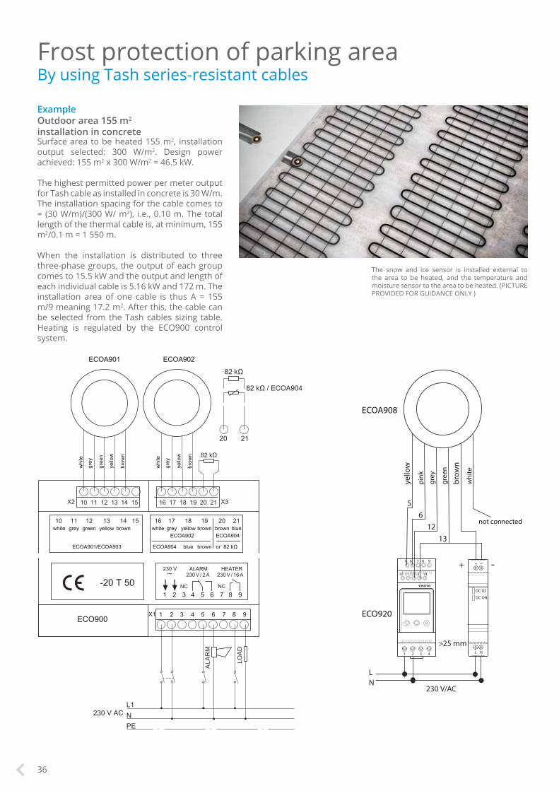
Frost protection of parking area By using Tash series-resistant cables
ExampleOutdoor area 155 m2
installation in concreteSurface area to be heated 155 m2, installation output selected: 300 W/m2. Design power achieved: 155 m2 x 300 W/m2 = 46.5 kW.
The highest permitted power per meter output for Tash cable as installed in concrete is 30 W/m. The installation spacing for the cable comes to = (30 W/m)/(300 W/ m2), i.e., 0.10 m. The total length of the thermal cable is, at minimum, 155 m2/0.1 m = 1 550 m.
When the installation is distributed to three three-phase groups, the output of each group comes to 15.5 kW and the output and length of each individual cable is 5.16 kW and 172 m. The installation area of one cable is thus A = 155 m/9 meaning 17.2 m2. After this, the cable can be selected from the Tash cables sizing table. Heating is regulated by the ECO900 control system.
The snow and ice sensor is installed external to the area to be heated, and the temperature and moisture sensor to the area to be heated. (PICTURE PROVIDED FOR GUIDANCE ONLY )
36

105
50
Frost protection of outdoor steps By using Tash cables
Example10 steps, installation width 0.9 meters, step advance 0.5 meters.Surface area to be heated: 10 x 0.9 m x 0,5 m = 4.5 m2. Installation power output selected: 300 W/m2, Design power achieved: 4.5 m2 x 300 W/m2 = 1 350 W.
The highest permitted power per meter output for Tash cable when installed in concrete is 30 W/m. The installation spacing for the cable comes to = (30 W/m)/(300 W/m2,), i.e., 0.10 m.
Five cables are installed to one step. Per step, the amount of cabling required is 5 x 0.9 m, i.e., 4.5 m.
The total length of the heating cable is:• steps 10 x 4.5 m = 45 m• step ascent 9 x 0.15 m = 1.35 m• return to connection point• 9 x 0.5 + 9 x 0.15 = 5.8 m total: 52
meters.
The specific resistance of the cable is 0.75 Ω/m, and Tash cable 0.82 Ω/m is selected from the sizing tables (page 30-31). Installation power output is to 1 240 W, heating cable power per meter output is 24 W and installation power per square meters output is 275 W/m2. Heating is controlled by installing an ECO900, ECO910 or ECO920 frost protection control thermostat to the panel board.
50Cabling starts 5 cm from the edge of the step. After this, the cable is installed at 10 cm intervals.
Series-resistant Tash cables are always installed as loops, with the cold leads led back to the connection box. (PICTURE PROVIDED FOR GUIDANCE ONLY )
37

1
2
3
4
5
6
Maintaining the temperature in tanks
Heating cables can be used to maintain the required temperature of various tanks in order to prevent excessive increases in the viscosity of the liquids within. Heating also prevents freezing damage to the structures.
When choosing the heating cable, all possible thermal losses in the tank and its base must be taken into account. These thermal losses are dependent on the tank’s shape, size, understructure type (foundation or stand), the insulation thickness used, the required temperature and the surrounding temperature.
The tank pipes must also be protected from freezing and insulated. Around one third of the tank’s top section can be left uncabled, but the entire tank must be carefully insulated.
The appropriate control units are ECO500 , ECO910 or ECO920 thermostats.
Stored liquids have a tendency to somehow escape their container. Thus, it is recommended to check whether the liquid in question can cause cable corrosion, and select the correct cable type for the application. Similarly, easily evaporating liquids may result in an environment classification that requires special solutions.
1. Fixing ribbon2. Tash heating cable3. Aluminium tape4. Heating cable / cold lead joint5. Sensor6. Insulation(PICTURE PROVIDED FOR GUIDANCE ONLY )
38

The high quality of our products guarantees reliable performance for years to come.
Ulla300 -cable heating mat....................................40Plug’n Heat -heating cable.....................................40Tash single-conductor heating cables..................41Optiheat self-regulating cables.............................41Tash accessories.....................................................41Optiheat accessories..............................................41Heating cable attachment accessories ...............42ECO500 thermostat................................................42ECO910 thermostat................................................42ECO920 thermostat................................................42ECO900 thermostat................................................42
Index.........................................................................43
Frost ProtectionProducts
39
Frost protection systems
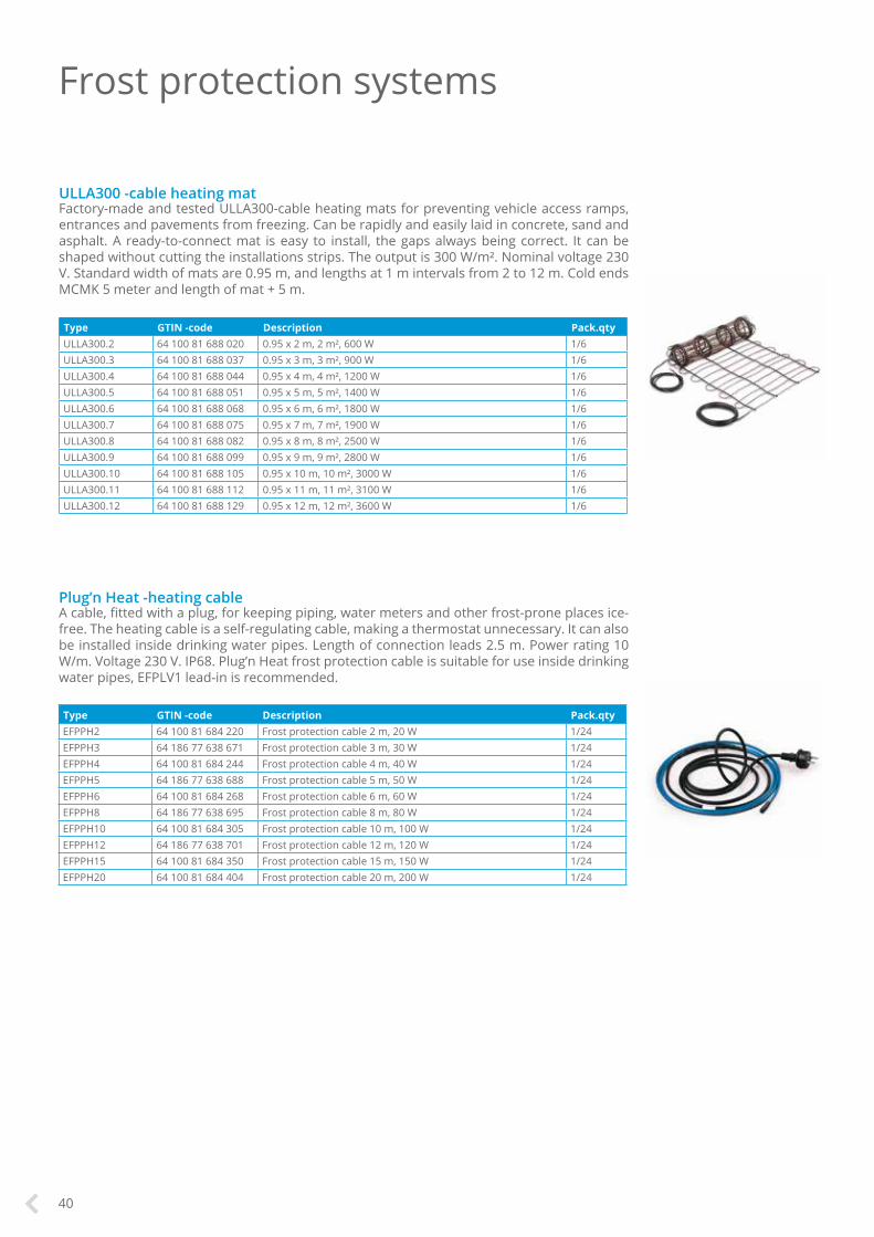
Type GTIN -code Description Pack.qtyULLA300.2 64 100 81 688 020 0.95 x 2 m, 2 m², 600 W 1/6ULLA300.3 64 100 81 688 037 0.95 x 3 m, 3 m², 900 W 1/6ULLA300.4 64 100 81 688 044 0.95 x 4 m, 4 m², 1200 W 1/6ULLA300.5 64 100 81 688 051 0.95 x 5 m, 5 m², 1400 W 1/6ULLA300.6 64 100 81 688 068 0.95 x 6 m, 6 m², 1800 W 1/6ULLA300.7 64 100 81 688 075 0.95 x 7 m, 7 m², 1900 W 1/6ULLA300.8 64 100 81 688 082 0.95 x 8 m, 8 m², 2500 W 1/6ULLA300.9 64 100 81 688 099 0.95 x 9 m, 9 m², 2800 W 1/6ULLA300.10 64 100 81 688 105 0.95 x 10 m, 10 m², 3000 W 1/6ULLA300.11 64 100 81 688 112 0.95 x 11 m, 11 m², 3100 W 1/6ULLA300.12 64 100 81 688 129 0.95 x 12 m, 12 m², 3600 W 1/6
ULLA300 -cable heating matFactory-made and tested ULLA300-cable heating mats for preventing vehicle access ramps, entrances and pavements from freezing. Can be rapidly and easily laid in concrete, sand and asphalt. A ready-to-connect mat is easy to install, the gaps always being correct. It can be shaped without cutting the installations strips. The output is 300 W/m². Nominal voltage 230 V. Standard width of mats are 0.95 m, and lengths at 1 m intervals from 2 to 12 m. Cold ends MCMK 5 meter and length of mat + 5 m.
Type GTIN -code Description Pack.qtyEFPPH2 64 100 81 684 220 Frost protection cable 2 m, 20 W 1/24EFPPH3 64 186 77 638 671 Frost protection cable 3 m, 30 W 1/24EFPPH4 64 100 81 684 244 Frost protection cable 4 m, 40 W 1/24EFPPH5 64 186 77 638 688 Frost protection cable 5 m, 50 W 1/24EFPPH6 64 100 81 684 268 Frost protection cable 6 m, 60 W 1/24EFPPH8 64 186 77 638 695 Frost protection cable 8 m, 80 W 1/24EFPPH10 64 100 81 684 305 Frost protection cable 10 m, 100 W 1/24EFPPH12 64 186 77 638 701 Frost protection cable 12 m, 120 W 1/24EFPPH15 64 100 81 684 350 Frost protection cable 15 m, 150 W 1/24EFPPH20 64 100 81 684 404 Frost protection cable 20 m, 200 W 1/24
Plug’n Heat -heating cableA cable, fitted with a plug, for keeping piping, water meters and other frost-prone places ice-free. The heating cable is a self-regulating cable, making a thermostat unnecessary. It can also be installed inside drinking water pipes. Length of connection leads 2.5 m. Power rating 10 W/m. Voltage 230 V. IP68. Plug’n Heat frost protection cable is suitable for use inside drinking water pipes, EFPLV1 lead-in is recommended.
40

Type GTIN -code Description Pack.qty EFPO10 64 100 04 313 107 Optiheat 10, power 10 W/m, blue 1/1000EFPO20 64 186 77 639 180 Optiheat 20/40, power 20 W/m, black 1/1000EFPO20.250 64 186 77 639 197 Optiheat 20/40, power 20 W/m, black 1/250 EFPORAMP 64 186 77 639 159 Optiheat Ramp, power 50 W/m, yellow 1/250
Tash single-conductor heating cablesThe TASH single-conductor series resistant cables are designed for keeping outdoor areas, pipes and containers ice-free. Outer sheet of cross linkable HFFR compound. Max loading 30 W/m (concrete), 25 W/m (sand), 20 W/m (pipe surface). Operating temperature under current 80 ºC, momentarily 160 ºC. Max voltage 500 V. Min. bending radius 5x outside diameter of cable.
Type GTIN -code Description Pack.qty TASH0.05 64 100 04 301 555 Tash-series resistant cable. 0.05 ohm/m 1/2000TASH0.1 64 100 04 301 500 Tash-series resistant cable. 0.1 ohm/m 1/2000TASH0.17 64 100 04 301 562 Tash-series resistant cable. 0.17 ohm/m 1/2000TASH0.21 64 100 04 301 517 Tash-series resistant cable. 0.21 ohm/m 1/2000TASH0.32 64 100 04 301 326 Tash-series resistant cable. 0.32 ohm/m 1/2000TASH0.45 64 100 04 301 579 Tash-series resistant cable. 0.45 ohm/m 1/2000TASH0.65 64 100 04 301 593 Tash-series resistant cable. 0.65 ohm/m 1/2000TASH0.82 64 100 04 301 586 Tash-series resistant cable. 0.82 ohm/m 1/2000TASH1 64 100 04 301 661 Tash-series resistant cable. 1.0 ohm/m 1/2000TASH1.5 64 100 04 301 609 Tash-series resistant cable. 1.5 ohm/m 1/2000TASH3 64 100 04 301 616 Tash-series resistant cable. 3 ohm/m 1/2000TASH6 64 100 04 301 630 Tash-series resistant cable. 6.0 ohm/m 1/2000TASH10 64 100 04 301 647 Tash-series resistant cable. 10 ohm/m 1/2000
Frost protection systems
Type GTIN -code Description Pack.qtyEFPLP1 64 186 77 630 002 Extension sleeve + termination accessory 1/20EFPLP2 64 186 77 630 019 Junction box + termination accessory 1/20EFPLP3 64 186 77 630 026 Optiheat – Optiheat extension 1/20EFPLP5 64 186 77 639 333 Splice package Optiheat Ramp 1/20EFPLV1 64 186 77 630 033 Lead-in for Optiheat 10-cable for water pipes 1/12
Optiheat accessoriesEFPLP1 jointing kit containing joint and shrink accessories for the watertight extension of a cable by means of a connector cable (MMJ or MMCK) and a termination accessory. EFPLP2 jointing kit for connecting a heating cable to a junction box or a termiantion accessory. The cable is laid from the point of installation to the box either as it is or in a protective tube. The kit includes a cable-shaped rubber seal. EFPLV1 pressure resistant lead-through for installing Optiheat 10 and Plug’n Heat cables inside a water pipe.
Type GTIN -code Description Pack.qtyEFPLP4 64 186 77 630 767 Jointing kit for single conductor Tash- and Lask heating cables 1/50
Tash accessoriesBy using EFPLP4 connection kit a single or a twin-conductor heating cable can be connected to a cold cable or another heating cable. The kit can also be used for connecting cold cables to both ends of a single conductor cable.
Optiheat self-regulating cablesEnsto Optiheat self-regulating frost protection cables are energy-efficient solutions for rainwater systems, roofs, stairs, ramps and outdoor areas.
41

Type GTIN -code Description Pack.qty
ECO900 64 186 77 630 866 Control device of frost protection in outdoor areas, ramps and roofs 1/180
ECOA901 64 186 77 630 873 Heated snow and ice sensor for ground installation 1/128
ECOA902 64 186 77 630 880 Humidity and temperature sensor for ground installation 1/128
ECOA903 64 186 77 630 897 Heated snow and ice sensor for rainwater guttering 1/180
ECOA904 64 186 77 630 903 Sensor for temperature measurement in gutters 1/180
ECO900-thermostatFully automatic snow- and ice melting control unit. Heat- and humidity informations. LCD-display with continuousinformation of temperature and humidity. Available versions in Finnish, Swedish, German, English, Czech and French. Diagnosis of faults and potential-free information in case of fault situation. Possibility of manual steering. DIN-rail mounting. 230 V.
Type GTIN -code Description Pack.qty
ECO500 64 186 77 635 830 Electronic thermostat, 3600 W, for frost protection of drain pipes 1/12
ECO500-thermostatFor frost protection control of pipes. Nominal voltage 230 V. Nominal current 16 A res. Max load 3600 W. Adjustment range +2 ... +35 ºC. Sensor 4 m, extendable up to 25 m with 2 x 1.5 mm². Sen-sor 47 kohm / 25 ºC. Box AP9. IP55. The sensor is installed to the top surface of the pipe when the cable is used inside the pipe. When using the cable outside the pipe, the sensor must be installed opposite of the heating cable, to the presumably coldest spot.
Type GTIN -code Description Pack.qty
ECO910 64 186 77 636 141 Frost protection thermostat, DIN-rail mounted 1/12
ECO910-thermostatDIN rail mounted frost protection thermostat with two sensors. Frost protection thermostat suits for the control of frost protection in outdoor areas, ramps, roofs and rainwater systems. Both two sensors are used for frost protection in outdoor areas and one sensor for frost protection in rainwater systems. Adjustment range of thermostat is –30 … +15 °C, IP20. Operating voltage 230 V. Maximum load 16 A. Sensor 47 kohm / 25°C. Length of sensor cable 4 m (extendable up to 25 m).
Type GTIN -code Description Pack.qtyLT20 64 186 77 631 764 Heat resistant tape, 12 mm x 20 m 1/16ALU50 64 186 77 631 702 Aluminium tape, 50 mm x 50 m 1/10SV10 64 186 77 631 795 Galvanized mesh, 50 mm x 10 m 1/10XBC1230 64 100 13 290 024 Galvanised attachment ribbon 20 m, installation gap 30 mm 1/10PPN6 64 186 77 631 771 Plastic mounting, 5.5 mm 1/100PPN8 64 100 13 290 611 Plastic mounting, 6.5 mm 1/100PPN10 64 186 77 637 766 Kaapelikiinnike syöksytorveen (25kpl) 25/300PPN12 64 186 77 637 773 Kaapelikiinnike räystäskouruun tai katolle (25kpl) 25/100VP300 64 186 77 632 082 Strain relief 1/20
Heating cable attachment accessoriesLT20 heat resistant tape for attaching a heating cable for piping. ALU50 aluminium tape, which is attached to the surface of the pipe in the same direction as the cable. SV10 is used for improving heat exchange to the pipe surface or valve. XBC1230 fixing strip, to which the heating cable is attached to ensure the correct gaps. PPN6 plastic mounting strip for attach-ment of Tash heating cable and assurance of correct gaps. PPN8 plastic mounting cable fixing strip for 2-conductor Tash heating cable attachment and to ensure correct gap. VP300 cable strain reliever for use when laying a heating cable in a drainpipe.
Type GTIN -code Description Pack.qty
ECO920 64 186 77 639 227 Frost protection thermostat, LCD 1/10
ECOA907 64 186 77 639 234 Roof sensor, humidity 1/12
ECOA908 64 186 77 639 241 Ground sensor, humidity and heat 1/10
ECOA909 64 186 77 639 302 ECO920 NTC-sensor, 10kohm 6 m 1/10
ECO920-thermostatFrost protection thermostat with LCD LCD-display. Frost protection thermostat suits for the control of outdoor areas and rainwater systems. The thermostat is mounted on a DIN rail, and the adjustment range of temperature is -20 °C...+10 °C.
42

Index of product types Index of SSTL-codes Index of GTIN -codes
Type PageALU50 42ECO500 42ECO900 42ECO910 42ECO920 42ECOA901 42ECOA902 42ECOA903 42ECOA904 42ECOA907 42ECOA908 42ECOA909 42EFPLP1 41EFPLP2 41EFPLP3 41EFPLP5 41EFPLV1 41EFPLV5 41EFPO10 41EFPO20 41EFPO20.250 41EFPORAMP 41EFPPH10 40EFPPH12 40EFPPH15 40EFPPH2 40EFPPH20 40EFPPH3 40EFPPH4 40EFPPH5 40EFPPH6 40EFPPH8 40LT20 42PPN6 42PPN8 42PPN10 42PPN12 42SV10 42TASH0.05 41TASH0.1 41TASH0.17 41TASH0.21 41TASH0.32 41TASH0.45 41TASH0.65 41TASH0.82 41TASH1 41TASH1.5 41TASH10 41TASH3 41TASH6 41ULLA300.10 40ULLA300.11 40ULLA300.12 40ULLA300.2 40ULLA300.3 40ULLA300.4 40ULLA300.5 40ULLA300.6 40ULLA300.7 40ULLA300.8 40ULLA300.9 40VP300 42XBC1230 42
GTIN -code Page64 100 04 301 326 4164 100 04 301 500 4164 100 04 301 517 4164 100 04 301 555 4164 100 04 301 562 4164 100 04 301 579 4164 100 04 301 586 4164 100 04 301 593 4164 100 04 301 609 4164 100 04 301 616 4164 100 04 301 630 4164 100 04 301 647 4164 100 04 301 661 4164 100 04 313 107 4164 100 13 290 024 4164 100 13 290 611 4164 100 81 684 220 4064 100 81 684 244 4064 100 81 684 268 4064 100 81 684 305 4064 100 81 684 350 4064 100 81 684 404 4064 100 81 688 020 4064 100 81 688 037 4064 100 81 688 044 4064 100 81 688 051 4064 100 81 688 068 4064 100 81 688 075 4064 100 81 688 082 4064 100 81 688 099 4064 100 81 688 105 4064 100 81 688 112 4064 100 81 688 129 4064 186 77 630 002 4164 186 77 630 019 4164 186 77 630 026 4164 186 77 630 033 4164 186 77 630 767 4164 186 77 630 866 4264 186 77 630 873 4264 186 77 630 880 4264 186 77 630 897 4264 186 77 630 903 4264 186 77 631 702 4264 186 77 631 764 4264 186 77 631 771 4264 186 77 631 795 4264 186 77 632 082 4164 186 77 635 830 4264 186 77 636 141 4264 186 77 637 766 4264 186 77 637 773 4264 186 77 638 671 4064 186 77 638 688 4064 186 77 638 695 4064 186 77 638 701 4064 186 77 639 180 4164 186 77 639 197 4164 186 77 639 159 4164 186 77 639 227 4264 186 77 639 234 4264 186 77 639 241 4264 186 77 639 302 4264 186 77 639 333 41
SSTL-code Page04 301 32 4104 301 50 4104 301 51 4104 301 55 4104 301 56 4104 301 57 4104 301 58 4104 301 59 4104 301 60 4104 301 61 4104 301 63 4104 301 64 4104 301 66 4104 310 39 4204 313 02 4104 313 10 4104 313 20 4104 313 32 4104 313 87 4104 313 89 4104 313 90 4104 313 91 4104 313 94 4104 313 95 4113 035 00 4213 035 01 4213 290 02 4213 290 60 4213 290 61 4235 300 20 4235 300 21 4235 300 22 4235 300 23 4235 300 24 4235 300 60 4235 300 80 4226 210 96 4226 210 97 4226 210 98 4226 213 00 4252 493 20 4152 493 21 4152 493 22 4181 684 22 4081 684 23 4081 684 24 4081 684 25 4081 684 26 4081 684 28 4081 684 30 4081 684 32 4081 684 35 4081 684 40 4081 688 02 4081 688 03 4081 688 04 4081 688 05 4081 688 06 4081 688 07 4081 688 08 4081 688 09 4081 688 10 4081 688 11 4081 688 12 40
43

Ensto Finland OyEnsio Miettisen katu 2, P.O. Box 77FIN-06101 Porvoo, [email protected]
ensto.com
EL10
EN/5
/201
7/10
00