frp repair reinforced concrete chimney
DESCRIPTION
Frp Repair Reinforced Concrete ChimneyTRANSCRIPT
David KellyDavid has over 19 years experience in the
Industrial Chimney Industry giving David
a specialist insight to the issues related
in the rigging of tall structures. David has
successfully managed numerous projects on
oil refineries and power stations worldwide.
Darren Smith MBADarren Smith has over 19 years experience
in the Industrial Chimney Industry. Having
started in sales, Darren now holds the position
of Business Development Director and is
responsible for promoting the Company
worldwide. Darren has a Masters Degree from
Keele University in England.
Andrew Kelly ICIOB B.Sc.Andrew Kelly has worked in the Industrial
Chimney & Construction Industries for
18 years starting as a junior technician,
progressing to his current position as
Director of Zenith Structural Access Solutions
Limited. A graduate of Heriot-Watt University,
Edinburgh, Andrew has held various construction positions
including Inspection Engineer, Quantity Surveyor, Construction
Manager and Commercial Manager.
Mo Ehsani PhD PE SEMo Ehsani is Professor Emeritus of Civil
Engineering at the University of Arizona and
President of QuakeWrap, Inc. He pioneered
the field of repair and retrofit of structures
with externally bonded FRP in the late
1980s and has applied this technique to numerous award-winning
projects worldwide.
IntroductionThis paper reviews the background, philosophy, repair scheme,
scope and methodology used in the inspection and strengthening
of a reinforced concrete chimney.
BackgroundThe climate in the country where the chimney is located is
continental. In the summer the temperatures can reach more than
53 Degrees Celsius and in winter the temperature can sink as
low as minus 58 Degrees Celsius. The structures are exposed to
some of the most extreme weather conditions this continent can
experience.
FRP Repair to a Reinforced Concrete Chimney
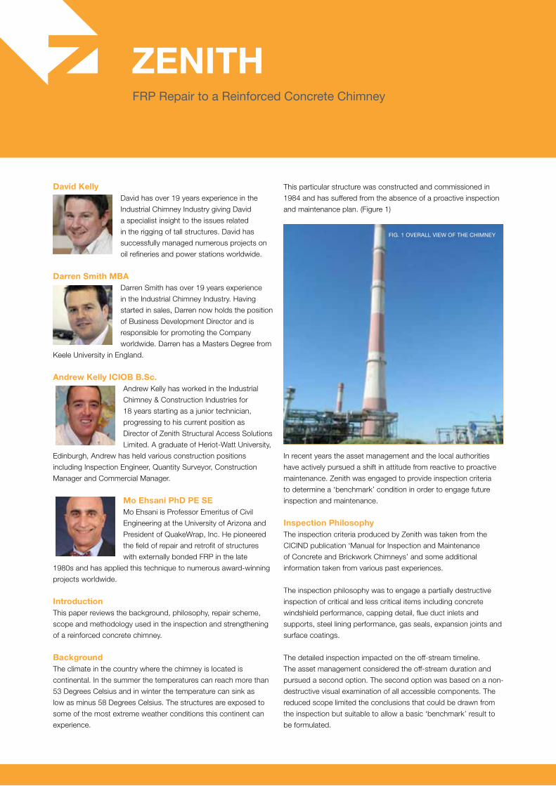
This particular structure was constructed and commissioned in
1984 and has suffered from the absence of a proactive inspection
and maintenance plan. (Figure 1)
In recent years the asset management and the local authorities
have actively pursued a shift in attitude from reactive to proactive
maintenance. Zenith was engaged to provide inspection criteria
to determine a ‘benchmark’ condition in order to engage future
inspection and maintenance.
Inspection PhilosophyThe inspection criteria produced by Zenith was taken from the
CICIND publication ‘Manual for Inspection and Maintenance
of Concrete and Brickwork Chimneys’ and some additional
information taken from various past experiences.
The inspection philosophy was to engage a partially destructive
inspection of critical and less critical items including concrete
windshield performance, capping detail, flue duct inlets and
supports, steel lining performance, gas seals, expansion joints and
surface coatings.
The detailed inspection impacted on the off-stream timeline.
The asset management considered the off-stream duration and
pursued a second option. The second option was based on a non-
destructive visual examination of all accessible components. The
reduced scope limited the conclusions that could be drawn from
the inspection but suitable to allow a basic ‘benchmark’ result to
be formulated.
Fig. 1 Overall view OF the chimney
The final scope required a visual examination only of the critical
and less critical components.
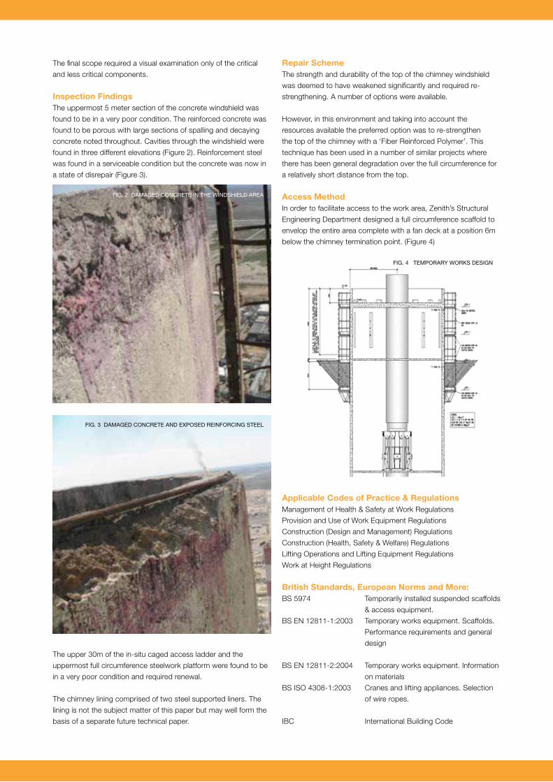
Inspection FindingsThe uppermost 5 meter section of the concrete windshield was
found to be in a very poor condition. The reinforced concrete was
found to be porous with large sections of spalling and decaying
concrete noted throughout. Cavities through the windshield were
found in three different elevations (Figure 2). Reinforcement steel
was found in a serviceable condition but the concrete was now in
a state of disrepair (Figure 3).
The upper 30m of the in-situ caged access ladder and the
uppermost full circumference steelwork platform were found to be
in a very poor condition and required renewal.
The chimney lining comprised of two steel supported liners. The
lining is not the subject matter of this paper but may well form the
basis of a separate future technical paper.
Repair SchemeThe strength and durability of the top of the chimney windshield
was deemed to have weakened significantly and required re-
strengthening. A number of options were available.
However, in this environment and taking into account the
resources available the preferred option was to re-strengthen
the top of the chimney with a ‘Fiber Reinforced Polymer’. This
technique has been used in a number of similar projects where
there has been general degradation over the full circumference for
a relatively short distance from the top.
Access MethodIn order to facilitate access to the work area, Zenith’s Structural
Engineering Department designed a full circumference scaffold to
envelop the entire area complete with a fan deck at a position 6m
below the chimney termination point. (Figure 4)
Applicable Codes of Practice & RegulationsManagement of Health & Safety at Work Regulations
Provision and Use of Work Equipment Regulations
Construction (Design and Management) Regulations
Construction (Health, Safety & Welfare) Regulations
Lifting Operations and Lifting Equipment Regulations
Work at Height Regulations
British Standards, European Norms and More:BS 5974 Temporarily installed suspended scaffolds
& access equipment.
BS EN 12811-1:2003 Temporary works equipment. Scaffolds.
Performance requirements and general
design
BS EN 12811-2:2004 Temporary works equipment. Information
on materials
BS ISO 4308-1:2003 Cranes and lifting appliances. Selection
of wire ropes.
IBC International Building Code
Fig. 2 DamageD cOncrete in the winDshielD area
Fig. 3 DamageD cOncrete anD expOseD reinFOrcing steel
Fig. 4 tempOrary wOrks Design
ASTM American Society for Testing and
Materials
ASTM D3039 Standard Test Method for Tensile
Properties of Polymer Matrix Composite
Materials
ACI American Concrete Institute
ACI 440.2R-08 Guide for the Design and Construction
of Externally Bonded FRP Systems for
Strengthening Concrete Structures.”
ACI 440 R-96 State-of-the-Art Report on Fiber
Reinforced Polymer (FRP) Reinforcement
for Concrete Structures.
ACI 503 R Pull-off test to determine FRP adhesion
to concrete substrate.
Governing Factors
• Environment
The repair scheme proposed was to limit any off-stream time to a
minimum. This repair scheme could be completed on-stream to
a safe distance from the top of the chimney (6.00 meters). One of
the flue liners was off-line whilst the other had a temporary heat
shield extension thereby allowing safe access to the work area.
• Resources
The design of the FRP retrofit was completed by QuakeWrap
engineers. The windshield area of the chimney presented signs
of deterioration caused by constant exposure of corrosive vapors
from the fumes. Repairing damaged areas with mortar alone was
not sufficient to guarantee reoccurrence of spalling; therefore,
alternative repair methods had to be considered. The repair
materials not only had to guarantee full bonding with the substrate,
but also confine the structure and protect it against corrosion for
years to come.
Fiber Reinforced Polymer (FRP) materials are very versatile and
offered unique advantages for repairing a structure of complex
shape with multiple openings. For this project, a biaxial glass
reinforcing fabric was selected. When properly installed, this fabric
provides a tensile force equivalent to a 10 mm reinforcing steel
at a spacing of 200 mm in both horizontal and vertical directions.
Visual inspections of the damaged sections indicated that this
level of reinforcement was more than the loss of strength that had
occurred due to the corrosion of reinforcing steel. The biaxial glass
fabric provides reinforcement in two orthogonal directions, allowing
the interception of potential cracks.
• Applicators Qualifications
1. A minimum of two (2) years experience applying composite fibre-
epoxy strengthening system to existing concrete elements.
2. Written certification from the manufacturer as an approved
installer of the manufacturer’s products.
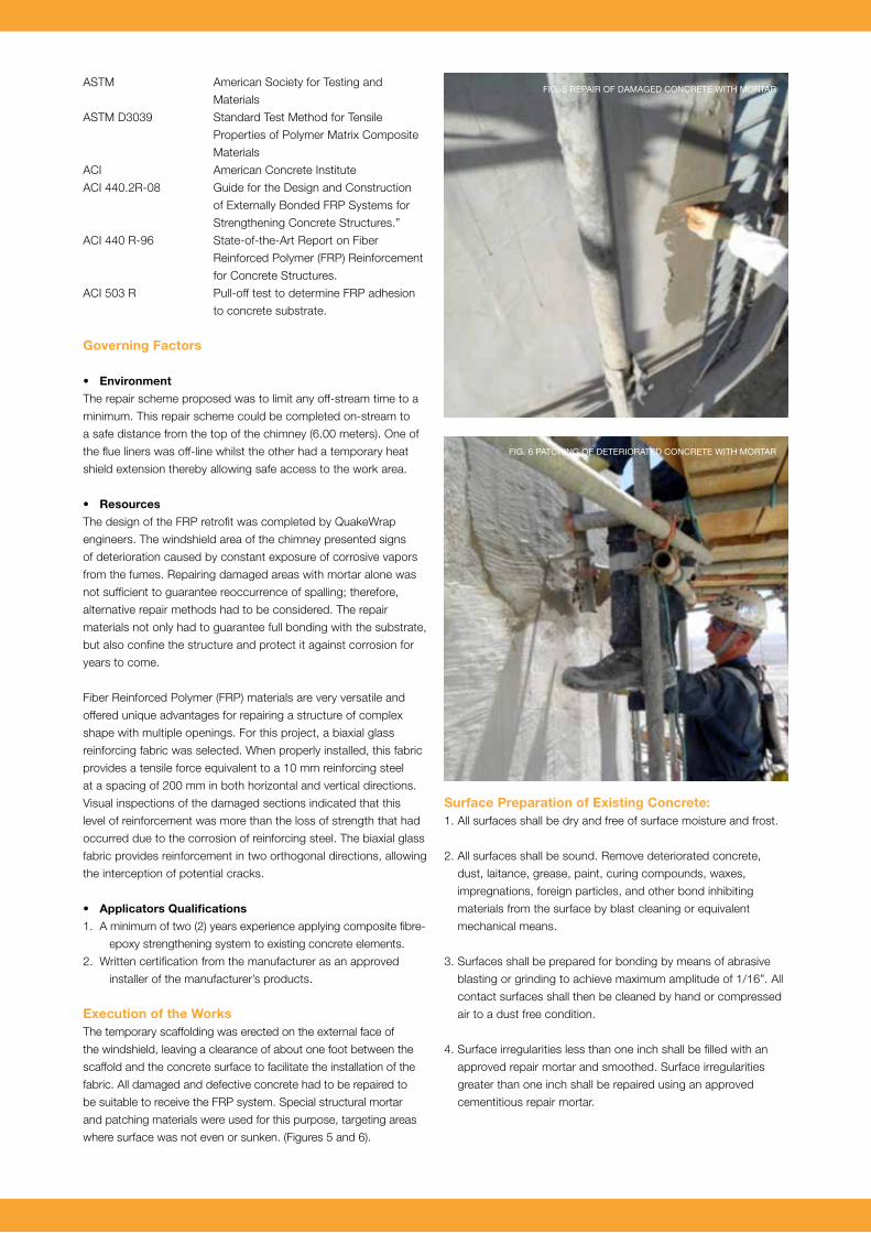
Execution of the WorksThe temporary scaffolding was erected on the external face of
the windshield, leaving a clearance of about one foot between the
scaffold and the concrete surface to facilitate the installation of the
fabric. All damaged and defective concrete had to be repaired to
be suitable to receive the FRP system. Special structural mortar
and patching materials were used for this purpose, targeting areas
where surface was not even or sunken. (Figures 5 and 6).
Surface Preparation of Existing Concrete:1. All surfaces shall be dry and free of surface moisture and frost.
2. All surfaces shall be sound. Remove deteriorated concrete,
dust, laitance, grease, paint, curing compounds, waxes,
impregnations, foreign particles, and other bond inhibiting
materials from the surface by blast cleaning or equivalent
mechanical means.
3. Surfaces shall be prepared for bonding by means of abrasive
blasting or grinding to achieve maximum amplitude of 1/16”. All
contact surfaces shall then be cleaned by hand or compressed
air to a dust free condition.
4. Surface irregularities less than one inch shall be filled with an
approved repair mortar and smoothed. Surface irregularities
greater than one inch shall be repaired using an approved
cementitious repair mortar.
Fig. 5 repair OF DamageD cOncrete with mOrtar
Fig. 6 patching OF DeteriOrateD cOncrete with mOrtar
5. External corners shall be rounded to at least a 1/2” radius when
perpendicular to fiber orientation and internal corners shall be
smoothed by trowelling epoxy mortar into the corners.
6. The adhesive strength of the surface shall be verified after
preparation by random pull off testing (ACI 503R) at the
direction of the Engineer. Minimum tensile strength is 200 psi
with concrete substrate failure, or as approved by the Engineer.
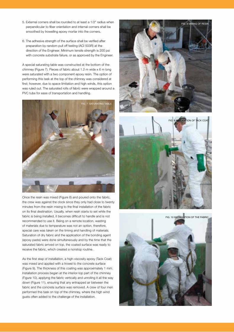
A special saturating table was constructed at the bottom of the
chimney (Figure 7). Pieces of fabric about 1.2 m wide x 6 m long
were saturated with a two component epoxy resin. The option of
performing this task at the top of the chimney was considered at
first; however, due to space limitation and high winds, this option
was ruled out. The saturated rolls of fabric were wrapped around a
PVC tube for ease of transportation and handling.
Once the resin was mixed (Figure 8) and poured onto the fabric,
the crew was against the clock since they only had close to twenty
minutes from the resin mixing to the final installation of the fabric
on its final destination. Usually, when resin starts to set while the
fabric is being installed, it becomes difficult to handle and is not
recommended to use it. Being on a remote location, wasting
of materials due to temperature was not an option, therefore,
special care was taken on the timing and handling of materials.
Saturation of dry fabric and the application of the bonding agent
(epoxy paste) were done simultaneously and by the time that the
saturated fabric arrived on top, the coated surface was ready to
receive the fabric, which created a nonstop routine.
As the first step of installation, a high-viscosity epoxy (Tack Coat)
was mixed and applied with a trowel to the concrete surface
(Figure 9). The thickness of this coating was approximately 1 mm.
Installation process began at the interior-top part of the chimney
(Figure 10), applying the fabric vertically and unrolling it all the way
down (Figure 11), ensuring that any entrapped air between the
fabric and the concrete surface was removed. A crew of four men
performed this task on top of the chimney, where the high wind
gusts often added to the challenge of the installation.
Fig. 7 saturating table
Fig. 8 mixing OF resin
Fig. 9 applicatiOn OF tack cOat
Fig. 10 installatiOn OF the Fabric
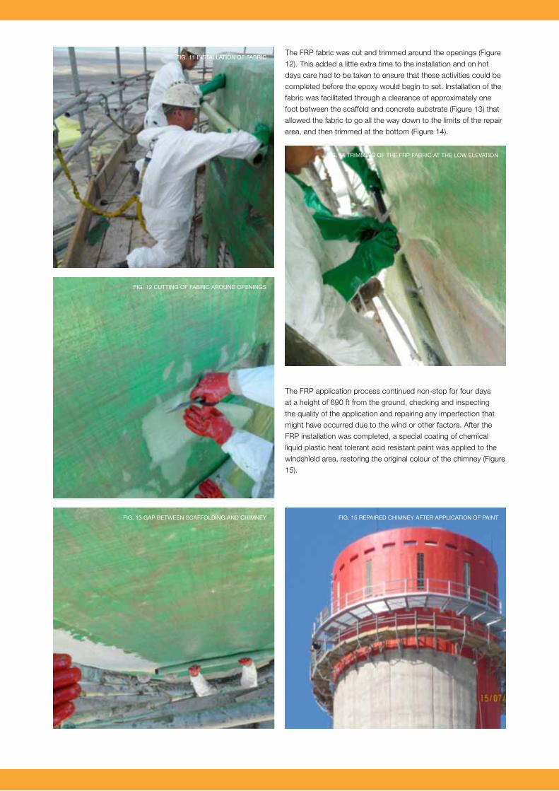
The FRP fabric was cut and trimmed around the openings (Figure
12). This added a little extra time to the installation and on hot
days care had to be taken to ensure that these activities could be
completed before the epoxy would begin to set. Installation of the
fabric was facilitated through a clearance of approximately one
foot between the scaffold and concrete substrate (Figure 13) that
allowed the fabric to go all the way down to the limits of the repair
area, and then trimmed at the bottom (Figure 14).
The FRP application process continued non-stop for four days
at a height of 690 ft from the ground, checking and inspecting
the quality of the application and repairing any imperfection that
might have occurred due to the wind or other factors. After the
FRP installation was completed, a special coating of chemical
liquid plastic heat tolerant acid resistant paint was applied to the
windshield area, restoring the original colour of the chimney (Figure
15).
Fig. 12 cutting OF Fabric arOunD Openings
Fig. 14 trimming OF the Frp Fabric at the lOw elevatiOn
Fig. 15 repaireD chimney aFter applicatiOn OF paint
Fig. 11 installatiOn OF Fabric
Fig. 13 gap between scaFFOlDing anD chimney

On completion of the FRP application, the top 30m of the caged
access ladder and in addition the top full circumference access
platform were replaced.
Future MaintenanceThe future inspection criteria have been developed to include
inspection of the modified region of the chimney and development
of a proactive maintenance scheme to ensure the longevity and
performance of the structure. The FRP system is not expected to
require any maintenance during its service life.
AcknowledgementsDave Kelly – Contracts Director
Scott Smith – Construction Supervisor and the Zenith Field Team.
Juan Carlos Romero – Project Engineer and FRP Installation
Supervisor, QuakeWrap, Inc.