fs-1018mfp km-1815 - service manual ebook filefs-1018mfp km-1815. 2dd contents 1-1 specifications...
TRANSCRIPT

SERVICEMANUAL
Published in June 2004842DD112Revision 2
FS-1018MFPKM-1815

2DD
CONTENTS
1-1 Specifications1-1-1 Specifications ....................................................................................................................................... 1-1-11-1-2 Name of parts ....................................................................................................................................... 1-1-3
(1) Main body ....................................................................................................................................... 1-1-3(2) Operation panel .............................................................................................................................. 1-1-4
1-2 Handling Precautions1-2-1 Drum .................................................................................................................................................... 1-2-11-2-2 Installation environment ....................................................................................................................... 1-2-1
1-3 Installation1-3-1 Unpacking and installation ................................................................................................................... 1-3-1
(1) Installation procedure ..................................................................................................................... 1-3-11-3-2 Connecting the cable ......................................................................................................................... 1-3-161-3-3 Installing the document processor (option) ........................................................................................ 1-3-181-3-4 Installing the expanding memory (option) .......................................................................................... 1-3-21
1-4 Maintenance Mode1-4-1 Maintenance mode ............................................................................................................................... 1-4-1
(1) Executing a maintenance item ....................................................................................................... 1-4-1(2) Maintenance mode item list ............................................................................................................ 1-4-2(3) Contents of maintenance mode items ............................................................................................ 1-4-3
1-4-2 System settings .................................................................................................................................. 1-4-18(1) Executing a system setting item ................................................................................................... 1-4-18(2) System settings ............................................................................................................................ 1-4-19
1-5 Troubleshooting1-5-1 Paper misfeed detection ...................................................................................................................... 1-5-1
(1) Paper misfeed indication ................................................................................................................ 1-5-1(2) Paper misfeed detection conditions ................................................................................................ 1-5-2(3) Paper misfeeds ............................................................................................................................... 1-5-4
1-5-2 Self-diagnosis ....................................................................................................................................... 1-5-8(1) Self-diagnostic function .................................................................................................................. 1-5-8(2) Self-diagnostic codes ..................................................................................................................... 1-5-8
1-5-3 Image formation problems ................................................................................................................. 1-5-13(1) No image appears (entirely white). ............................................................................................... 1-5-14(2) No image appears (entirely black). ............................................................................................... 1-5-14(3) Image is too light. ......................................................................................................................... 1-5-15(4) Background is visible. ................................................................................................................... 1-5-15(5) A white line appears longitudinally. .............................................................................................. 1-5-15(6) A black line appears longitudinally. .............................................................................................. 1-5-16(7) A black line appears laterally. ....................................................................................................... 1-5-16(8) One side of the print image is darker than the other. ................................................................... 1-5-16(9) Black dots appear on the image. .................................................................................................. 1-5-17
(10) Image is blurred. ........................................................................................................................... 1-5-17(11) The leading edge of the image is consistently misaligned with the original. ................................ 1-5-17(12) Paper creases. ............................................................................................................................. 1-5-18(13) Offset occurs. ............................................................................................................................... 1-5-18(14) Image is partly missing. ................................................................................................................ 1-5-18(15) Fixing is poor. ............................................................................................................................... 1-5-19(16) Image center does not align with the original center. ................................................................... 1-5-19
1-5-4 Electrical problems ............................................................................................................................. 1-5-20(1) The machine does not operate when the power switch is turned on. ........................................... 1-5-20(2) The main motor does not operate. (C2000) ................................................................................. 1-5-20(3) The scanner motor does not operate. .......................................................................................... 1-5-20(4) Cooling fan does not operate. ...................................................................................................... 1-5-20

2DD
(5) The feed clutch does not operate. ................................................................................................ 1-5-20(6) The MP feed clutch does not operate. .......................................................................................... 1-5-21(7) The registration clutch does not operate. ..................................................................................... 1-5-21(8) The eraser lamp does not turn on. ............................................................................................... 1-5-21(9) The exposure lamp does not turn on. ........................................................................................... 1-5-21
(10) The exposure lamp does not turn off. ........................................................................................... 1-5-21(11) The heater lamp does not turn on. ............................................................................................... 1-5-21(12) The heater lamp does not turn off. ............................................................................................... 1-5-21(13) Main charging is not performed. ................................................................................................... 1-5-22(14) Transfer charging is not performed. ............................................................................................. 1-5-22(15) A paper jam in the paper feed or exit section is indicated
when the power switch is turned on. ............................................................................................ 1-5-22(16) The message requesting cover to be closed is displayed
when the front cover is closed. ..................................................................................................... 1-5-22(17) Others. .......................................................................................................................................... 1-5-22
1-5-5 Mechanical problems ......................................................................................................................... 1-5-23(1) No primary paper feed. ................................................................................................................. 1-5-23(2) No secondary paper feed. ............................................................................................................ 1-5-23(3) Skewed paper feed. ...................................................................................................................... 1-5-23(4) The scanner does not travel. ........................................................................................................ 1-5-23(5) Multiple sheets of paper are fed at one time. ................................................................................. 1-5-23(6) Paper jams. .................................................................................................................................. 1-5-23(7) Abnormal noise is heard. .............................................................................................................. 1-5-23
1-6 Assembly and Disassembly1-6-1 Precautions for assembly and disassembly ......................................................................................... 1-6-1
(1) Precautions ..................................................................................................................................... 1-6-11-6-2 Removing the process unit ................................................................................................................... 1-6-21-6-3 Removing the principal outer covers .................................................................................................... 1-6-3
(1) Removing the front top cover/face-down output tray ...................................................................... 1-6-3(2) Removing the right cover ................................................................................................................ 1-6-4(3) Removing the left cover .................................................................................................................. 1-6-4
1-6-4 Removing the feed roller ...................................................................................................................... 1-6-51-6-5 Removing the MP feed roller ................................................................................................................ 1-6-61-6-6 Removing the transfer roller ................................................................................................................. 1-6-81-6-7 Removing the principal circuit boards .................................................................................................. 1-6-9
(1) Removing the engine board ........................................................................................................... 1-6-9(2) Removing the main board ............................................................................................................ 1-6-10(3) Removing the power supply board and high voltage board ......................................................... 1-6-12(4) Removing the bias board .............................................................................................................. 1-6-13
1-6-8 Removing the main motor and drive unit ........................................................................................... 1-6-141-6-9 Removing and splitting the fuser unit ................................................................................................. 1-6-18
(1) Removing the separation craws ................................................................................................... 1-6-20(2) Removing the heater lamp ........................................................................................................... 1-6-21(3) Removing the heat roller .............................................................................................................. 1-6-22(4) Removing the thermistor .............................................................................................................. 1-6-24(5) Removing the thermal cutout ........................................................................................................ 1-6-25(6) Removing the press roller ............................................................................................................. 1-6-26
1-6-10 Removing and scanner unit ............................................................................................................... 1-6-271-6-11 Removing the laser scanner unit and the eraser lamp ....................................................................... 1-6-291-6-12 Removing the ISU unit ....................................................................................................................... 1-6-321-6-13 Removing the exposure lamp ............................................................................................................ 1-6-341-6-14 Removing the scanner mirror A ......................................................................................................... 1-6-361-6-15 Removing the scanner motor ............................................................................................................. 1-6-371-6-16 Removing the main charger unit ........................................................................................................ 1-6-401-6-17 Adjustment the maintenance mode .................................................................................................... 1-6-41
(1) Adjusting the leading edge registration of image printing ............................................................. 1-6-41(2) Adjusting the center line of image printing .................................................................................... 1-6-42(3) Adjusting the amount of slack in the paper ................................................................................... 1-6-43

2DD
(4) Adjusting magnification of the scanner in the main scanning direction ........................................ 1-6-44(5) Adjusting magnification of the scanner in the auxiliary scanning direction ................................... 1-6-45(6) Adjusting the scanner leading edge registration ........................................................................... 1-6-46(7) Adjusting the scanner center line ................................................................................................. 1-6-47(8) Adjusting the margins for scanning an original on the contact glass ............................................ 1-6-48(9) Adjusting the DP magnification ..................................................................................................... 1-6-49
(10) Adjusting the DP leading edge registration .................................................................................. 1-6-50(11) Adjusting the DP trailing edge registration ................................................................................... 1-6-51(12) Adjusting the DP center line ......................................................................................................... 1-6-52(13) Adjusting the margins for scanning the original from the DP ........................................................ 1-6-53
1-7 Requirements on PWB Replacement1-7-1 Upgrading the firmware on the main board .......................................................................................... 1-7-1
2-1 Mechanical construction2-1-1 Paper feeding system .......................................................................................................................... 2-1-1
(1) Paper feed control .......................................................................................................................... 2-1-2(2) Paper feeding mechanism .............................................................................................................. 2-1-3
2-1-2 Original scanning system ..................................................................................................................... 2-1-4(1) ISU unit ........................................................................................................................................... 2-1-6
2-1-3 Electrophotographic system ................................................................................................................. 2-1-7(1) Electrophotographic cycle .............................................................................................................. 2-1-7
(1-1) Process unit mechanism ....................................................................................................... 2-1-8(2) Main charging ................................................................................................................................. 2-1-9
(2-1) Photo conductive drum .......................................................................................................... 2-1-9(2-2) Charging the drum ............................................................................................................... 2-1-10
(3) Exposure ...................................................................................................................................... 2-1-11(3-1) Laser scanner unit ............................................................................................................... 2-1-12(3-2) Drum surface potential ........................................................................................................ 2-1-13
(4) Development ................................................................................................................................ 2-1-14(5) Transfer ........................................................................................................................................ 2-1-15(6) Fusing ........................................................................................................................................... 2-1-16
(6-1) Fuser unit mechanism ......................................................................................................... 2-1-17(7) Cleaning ....................................................................................................................................... 2-1-18
2-2 Electrical Parts Layout2-2-1 Electrical parts layout ........................................................................................................................... 2-2-1
(1) Main unit ......................................................................................................................................... 2-2-1(2) Scanner unit ................................................................................................................................... 2-2-2
2-3 Operation of the PWBs2-3-1 Main board ........................................................................................................................................... 2-3-12-3-2 Engine board ........................................................................................................................................ 2-3-7
(1) Eraser lamp control circuit .............................................................................................................. 2-3-9(2) Heater lamp control circuit ............................................................................................................ 2-3-10(3) Polygon motor control circuit ........................................................................................................ 2-3-13
2-3-3 Power supply board ........................................................................................................................... 2-3-172-3-4 Bias board .......................................................................................................................................... 2-3-192-3-5 High voltage board ............................................................................................................................. 2-3-20
(1) Interlock switch ............................................................................................................................. 2-3-212-3-6 CCD board ......................................................................................................................................... 2-3-222-3-7 Operation board ................................................................................................................................. 2-3-242-3-8 Scanner board .................................................................................................................................... 2-3-26
2-4 AppendixesTiming chart No. 1 .......................................................................................................................................... 2-4-1Timing chart No. 2 .......................................................................................................................................... 2-4-2Timing chart No. 3 .......................................................................................................................................... 2-4-3Wiring diagram ............................................................................................................................................... 2-4-4

2DD-2
1-1-1
1-1-1 Specifications
Type ............................................... DesktopCopying system.............................. Indirect electrostatic systemOriginals ......................................... Sheets of paper (Maximum original size: folio/81/2" × 14" [legal])
Platen: Sheets of paper, books, 3-dimensional objects (Maximum original size: folio/81/2" × 14" [legal])
Original feed system ...................... Contact glass: fixedDocument processor (optional): sheet-through
Copy paper .................................... Cassette: Plain paper (60 - 105 g/m2])MP tray: Plain paper (60 - 163 g/m2])Special paper: Transparencies, letterhead, colored paper, recycled paperNote: Use the MP tray for special paper.
Copying sizes ................................. Maximum: folio/81/2" × 14" [legal]Minimum: A6R /51/2" × 81/2"
Magnification ratios ........................ Manual mode: 50 - 200%, 1% incrementsCopying speed ............................... At 100% magnification, platen:
A4/81/2" × 11": 18 copies/min.A5: 18 copies/min.81/2" × 14": 15 copies/min.At 100% magnification, document processor:A4/81/2" × 11": 18 copies/min.
First copy speed ............................. Apporox. 10 s (A4/81/2" × 11", original placed on the platen)Warm-up time ................................. Within 30 s
Recovery from the low power mode: Within 10 sRecovery from the sleep mode: Within 15 s(at room temperature 23°C/73.4°F, humidity 60% RH)
Paper feed system ......................... Cassette: 250 sheets (80 g/m2)MP tray: 50 sheets (80 g/m2)
Stacking capacity ........................... Output tray: Approx. 150 sheets (80 g/m2)Face-up tray: 30 sheets (80 g/m2)
Standard memory........................... 96 MB (64 MB of system memory and 32 MB of additional memory)(Approx. 70 pages of memory possible with letter size, 5%, Text+Photo mode)
Additional memory ......................... 1 slot (64 MB, 128 MB or 256 MB)Continuous copying........................ 1 - 999 sheetsScanning system ............................ Flat bed scanning by CCD image sensorResolution ...................................... Reading (scanning) 600 × 600 dpi
Writing (printing) 600 × 600 dpiOriginal quality mode ..................... Text+Photo, Photo and TextLight source.................................... Cold cathode lampPhotoconductor .............................. OPC (drum diameter 30 mm)Charging system ............................ Single positive corona chargingDeveloping system ......................... Single element reversing processTransfer system ............................. Transfer rollerFixing system ................................. Heat roller
Heat source: halogen heaters (750 W)Control temperature: 190°C/374°F (at normal ambient temperature)Abnormally high temperature protection device: thermal cutout
Charge erasing system .................. Exposure by cleaning lampCleaning system............................. Cleaning bladeDimensions .................................... 496 (W) × 421 (D) × 385 (H) mm
199/16" (W) × 165/8" (D) × 153/16" (H)Weight ............................................ Approx. 14.5 kg/32.0 lbsFloor requirements ......................... 496 (W) × 740 (D) mm
199/16" (W) × 293/16" (D)Functions........................................ Auto exposure adjustment, Eco-copy mode, Zoom mode, Preset zoom mode,
Off mode, Low power mode, Layout modes, Sort mode and Program functionPower source ................................. 120 V AC, 60 Hz, 7.8 A
220 - 240 V AC, 50/60 Hz, 4.0 APower consumption........................ 854 WOptions ........................................... Paper feeder, Document processor and Additional memory
2DD-2
1-1-2
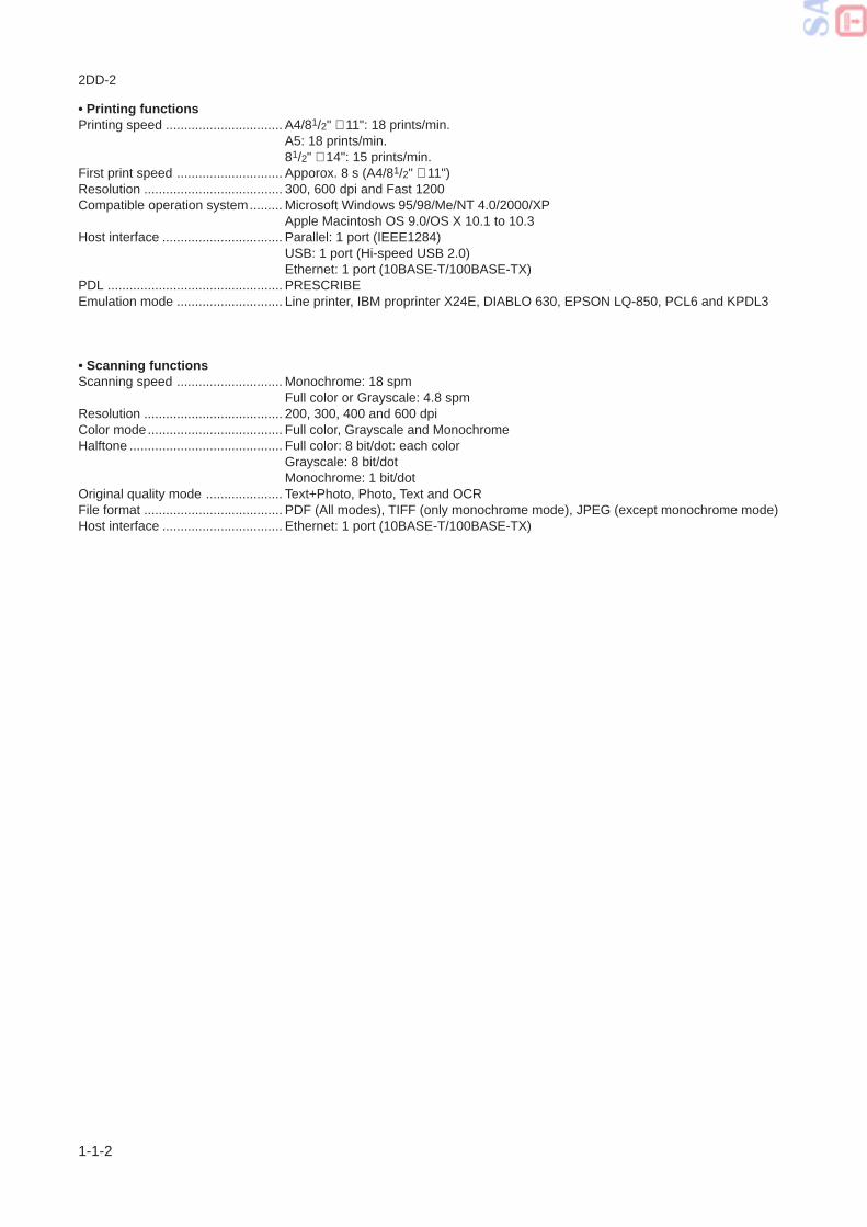
• Printing functionsPrinting speed ................................ A4/81/2" × 11": 18 prints/min.
A5: 18 prints/min.81/2" × 14": 15 prints/min.
First print speed ............................. Apporox. 8 s (A4/81/2" × 11")Resolution ...................................... 300, 600 dpi and Fast 1200Compatible operation system......... Microsoft Windows 95/98/Me/NT 4.0/2000/XP
Apple Macintosh OS 9.0/OS X 10.1 to 10.3Host interface ................................. Parallel: 1 port (IEEE1284)
USB: 1 port (Hi-speed USB 2.0)Ethernet: 1 port (10BASE-T/100BASE-TX)
PDL ................................................ PRESCRIBEEmulation mode ............................. Line printer, IBM proprinter X24E, DIABLO 630, EPSON LQ-850, PCL6 and KPDL3
• Scanning functionsScanning speed ............................. Monochrome: 18 spm
Full color or Grayscale: 4.8 spmResolution ...................................... 200, 300, 400 and 600 dpiColor mode..................................... Full color, Grayscale and MonochromeHalftone .......................................... Full color: 8 bit/dot: each color
Grayscale: 8 bit/dotMonochrome: 1 bit/dot
Original quality mode ..................... Text+Photo, Photo, Text and OCRFile format ...................................... PDF (All modes), TIFF (only monochrome mode), JPEG (except monochrome mode)Host interface ................................. Ethernet: 1 port (10BASE-T/100BASE-TX)

2DD-1
1-1-3
Figure 1-1-1 Names of parts
1-1-2 Names of parts
(1) Main body
1 Original cover2 Contact glass3 Original size indicator4 Operation panel5 Front top cover6 Front cover7 Process unit8 Toner container9 Lock lever0 Toner container release lever! Main charger cleaner@ Cassette# Paper guide$ Paper stopper
2
›
‹
¤
@
^
& *
( (
)
fifl
‡
⁄
#
#
1
3
5
6
7
89 0
!
$%
4
% Stopper extension lock^ Face-down output tray& MP tray* Extension tray( Slider) Power switch⁄ Face-up output tray¤ Power cord‹ DP interface connector› Memory coverfi Parallel interface connectorfl USB interface connector‡ Network interface connector

2DD
1-1-4
(2) Operation panel
1 Status key and indicator2 Copy key and indicator3 E-mail (Scan) key and indicator4 One-touch keys (1 to 8)5 Scan color select key and indicator6 Scan resolution key and indicator7 Function key and indicator8 Print indicator9 Send/Receive indicator0 Error indicator! System menu/Counter key
and indicator@ Keypad# Reset/Power key$ Main power indicator
Figure 1-1-2
% Original quality key and indicator^ Original size key and indicator& Exposure key and indicator* Paper select key and indicator( Message display) Left select key⁄ Right select key¤ Back key‹ Left cursor key› Up cursor keyfi Down cursor keyfl Right cursor key‡ Enter key— Stop/Clear key· Start key and indicator
1
3 % & ( ) ⁄ ‹ › ‡ fl — ·
^ * ¤ fi
2 4 5 6 7 8 9 0 ! @ # $

PARTS LISTPublished in Apr.’04
842DD120
FS-1018MFPKM-1815

NOTE
1.Indicate parts number and machine model when placing an order.
eg. Parts Number Parts Name Machine Model Cycle Quantity
2DD04020 LID TOP FS-1018MFP/KM-1815 50Hz 1
2.Service calls and freight will be charged separately.
3.Symbols in the "Parts Number" column.
• Parts with "'" indicates the spare parts and the parts without "'" can not be supplied.
• Parts with "•" are component parts or sub-assemblies of the assembly appearing immediately above them.
eg. Parts Number Parts Name Parts Number Parts Name
2DC93102 PARTS,MPF COVER SP •2A806730 TRAY MPF A
•2A806740 TRAY MPF B
4.See the last page of this parts list for the classification of the screws in the illustrations.
FIG.1 EXTERIOR COVERS · · · · · · · · · · · · · · · · · · · · · · · · · · · · 2FIG.2 FRAMES & PAPER FEED SECTION I · · · · · · · · · · · · · · · 4FIG.3 PAPER FEED SECTION II & LSU · · · · · · · · · · · · · · · · · · 8FIG.4 DRIVING SECTION · · · · · · · · · · · · · · · · · · · · · · · · · · · · · 10FIG.5 PROCESS UNIT · · · · · · · · · · · · · · · · · · · · · · · · · · · · · · · · 12FIG.6 FUSER UNIT · · · · · · · · · · · · · · · · · · · · · · · · · · · · · · · · · · · 14FIG.7 CASSETTE · · · · · · · · · · · · · · · · · · · · · · · · · · · · · · · · · · · · 16FIG.8 OPTICAL SECTION · · · · · · · · · · · · · · · · · · · · · · · · · · · · · 18FIG.9 OPERATION UNIT & ORIGINAL HOLDER · · · · · · · · · · · 20FIG.10 TOOLS & SUPPLIED PARTS · · · · · · · · · · · · · · · · · · · · · · 22
• INDEX · · · · · · · · · · · · · · · · · · · · · · · · · · · · · · · · · · · · · · · 24
CONTENTS

2DD
– 2 –
FIG. 1 EXTERIOR COVERS
9
8
31
2
5
7
10
4
61112
13
15
15
1716
18
19
14
14
HCN
HCN
BUD
BUD
HAY
BHA
BHA
BHA
BHA
BHA

Kyocera-Mita FS-1018MFP, KM-1815 service manual
Kyocera-Mita FS-1018MFP, KM-1815 service manual
Kyocera-Mita FS-1018MFP, KM-1815 service manual
Kyocera-Mita FS-1018MFP, KM-1815 service manual
Kyocera-Mita FS-1018MFP, KM-1815 service manual
Kyocera-Mita FS-1018MFP, KM-1815 service manual
Kyocera-Mita FS-1018MFP, KM-1815 service manual
Kyocera-Mita FS-1018MFP, KM-1815 service manual
Kyocera-Mita FS-1018MFP, KM-1815 service manual