ft43, ft44, ft46 and ft47 ball float steam traps
TRANSCRIPT

IM-S02-30 CMGT Issue 14 1
FT43, FT44, FT46 and FT47 Ball Float Steam Traps
1. Safety information
2. General product information
3. Installation
4. Commissioning
5. Operation
6. Maintenance and spare parts
0667050/14
FT43, FT44, FT46 and FT47Ball Float Steam Traps
Installation and Maintenance Instructions
IM-S02-30CMGT Issue 14
© Copyright 2022
Printed in GB

IM-S02-30 CMGT Issue 142
FT43, FT44, FT46 and FT47 Ball Float Steam Traps
Safe operation of these products can only be guaranteed if they are properly installed, commissioned, used and maintained by qualified personnel (see Section 1.11) in compliance with the operating instructions. General installation and safety instructions for pipeline and plant construction, as well as the proper use of tools and safety equipment must also be complied with.
1.1 Intended useReferring to the Installation and Maintenance Instructions, name-plate and Technical Information Sheet, check that the product is suitable for the intended use/application. The products listed below comply with the requirements of the EU Pressure Equipment Directive/UK
Pressure Equipment (Safety) Regulations and carry the mark when so required.
The products fall within the following Pressure Equipment Directive categories:
Product Group 2Gases
Group 2Liquids
FT43
DN15 - DN40 SEP SEP
DN50 1 SEP
DN80 - DN100 2 SEP
FT44, FT46 and FT47
DN15 - DN20 SEP SEP
DN25 - DN50 1 SEP
DN80 - DN100 (FT44 only) 2 SEP
i) The products have been specifically designed for use on steam, air or water/condensate which are in Group 2 of the above mentioned Pressure Equipment Directive.
ii) Check material suitability, pressure and temperature and their maximum and minimum values. If the maximum operating limits of the product are lower than those of the system in which it is being fitted, or if malfunction of the product could result in a dangerous overpressure or overtemperature occurrence, ensure a safety device is included in the system to prevent such over-limit situations.
iii) Determine the correct installation situation and direction of fluid flow.
iv) Spirax Sarco products are not intended to withstand external stresses that may be induced by any system to which they are fitted. It is the responsibility of the installer to consider these stresses and take adequate precautions to minimise them.
v) Remove protection covers from all connections and protective film from all name-plates, where appropriate, before installation on steam or other high temperature applications.
1.2 AccessEnsure safe access and if necessary a safe working platform (suitably guarded) before attempting to work on the product. Arrange suitable lifting gear if required.
1.3 LightingEnsure adequate lighting, particularly where detailed or intricate work is required.
1. Safety information

IM-S02-30 CMGT Issue 14 3
FT43, FT44, FT46 and FT47 Ball Float Steam Traps
1.4 Hazardous liquids or gases in the pipelineConsider what is in the pipeline or what may have been in the pipeline at some previous time. Consider: flammable materials, substances hazardous to health, extremes of temperature.
1.5 Hazardous environment around the productConsider: explosion risk areas, lack of oxygen (e.g. tanks, pits), dangerous gases, extremes of temperature, hot surfaces, fire hazard (e.g. during welding), excessive noise, moving machinery.
1.6 The systemConsider the effect on the complete system of the work proposed. Will any proposed action (e.g. closing isolation valves, electrical isolation) put any other part of the system or any personnel at risk? Dangers might include isolation of vents or protective devices or the rendering ineffective of controls or alarms. Ensure isolation valves are turned on and off in a gradual way to avoid system shocks.
1.7 Pressure systems Ensure that any pressure is isolated and safely vented to atmospheric pressure. Consider double isolation (double block and bleed) and the locking or labelling of closed valves. Do not assume that the system has depressurised even when the pressure gauge indicates zero.
1.8 TemperatureAllow time for temperature to normalise after isolation to avoid danger of burns.
1.9 Tools and consumablesBefore starting work ensure that you have suitable tools and/or consumables available. Use only genuine Spirax Sarco replacement parts.
1.10 Protective clothingConsider whether you and/or others in the vicinity require any protective clothing to protect against the hazards of, for example, chemicals, high/low temperature, radiation, noise, falling objects, and dangers to eyes and face.
1.11 Permits to workAll work must be carried out or be supervised by a suitably competent person.Installation and operating personnel should be trained in the correct use of the product according to the Installation and Maintenance Instructions.Where a formal 'permit to work' system is in force it must be complied with. Where there is no such system, it is recommended that a responsible person should know what work is going on and, where necessary, arrange to have an assistant whose primary responsibility is safety.Post 'warning notices' if necessary.

IM-S02-30 CMGT Issue 144
FT43, FT44, FT46 and FT47 Ball Float Steam Traps
1.12 HandlingManual handling of large and/or heavy products may present a risk of injury. Lifting, pushing, pulling, carrying or supporting a load by bodily force can cause injury particularly to the back. You are advised to assess the risks taking into account the task, the individual, the load and the working environment and use the appropriate handling method depending on the circumstances of the work being done.
1.13 Residual hazardsIn normal use the external surface of the product may be very hot. If used at the maximum permitted operating conditions the surface temperature of some products may reach temperatures in excess of 300 °C (572 °F).Many products are not self-draining. Take due care when dismantling or removing the product from an installation (refer to 'Maintenance instructions').
1.14 FreezingProvision must be made to protect products which are not self-draining against frost damage in environments where they may be exposed to temperatures below freezing point.
1.15 DisposalUnless otherwise stated in the Installation and Maintenance Instructions, this product is recyclable and no ecological hazard is anticipated with its disposal providing due care is taken.
1.16 Returning productsCustomers and stockists are reminded that under EC Health, Safety and Environment Law, when returning products to Spirax Sarco they must provide information on any hazards and the precautions to be taken due to contamination residues or mechanical damage which may present a health, safety or environmental risk. This information must be provided in writing including Health and Safety data sheets relating to any substances identified as hazardous or potentially hazardous.
1.17 Working safely with cast iron products on steamCast iron products are commonly found on steam and condensate systems. If installed correctly using good steam engineering practices, it is perfectly safe. However, because of its mechanical properties, it is less forgiving compared to other materials such as SG iron or carbon steel. The following are the good engineering practices required to prevent waterhammer and ensure safe working conditions on a steam system.
Safe handlingCast Iron is a brittle material. If the product is dropped during installation and there is any risk of damage the product should not be used unless it is fully inspected and pressure tested by the manufacturer.

IM-S02-30 CMGT Issue 14 5
FT43, FT44, FT46 and FT47 Ball Float Steam Traps
Prevention of water hammer Steam trapping on steam mains:
Steam Mains - Do's and Don'ts:
Steam Steam
Flow Flow
30 - 50 metre intervalsGradient 1:100Gradient 1:100
Trap setTrap set
Trap set
CondensateCondensate
Condensate
Steam
Steam

IM-S02-30 CMGT Issue 146
FT43, FT44, FT46 and FT47 Ball Float Steam Traps
Prevention of tensile stressing Pipe misalignment:
Installing products or re-assembling after maintenance:
Thermal expansion:
Do not over tighten.Use correct torque figures.
11
4 2
3
82
6
3
7
Flange bolts should be gradually tightened across diameters to ensure even load and alignment.
Guides
Guides
Limit rods
Limit rods
Fixing pointMedium distance
Small lateral
movement
Small lateral movement
Large lateral movement
Large lateral movement
Short distance Fixing point
Axial movement
Axial movement
Guides
Guides
5
4

IM-S02-30 CMGT Issue 14 7
FT43, FT44, FT46 and FT47 Ball Float Steam Traps
2.1 General descriptionThe FT43 - cast iron, FT44 - carbon steel, FT46 - austenitic stainless steel and FT47 - SG iron ball float steam traps have stainless steel working internals and automatic built-in air venting facility. These traps are supplied with integrally flanged connections (for horizontal or vertical installations) and can be maintained without disturbing the pipework. Please be aware that the flow direction is not the same for all FT trap types or sizes but will be clearly marked on the trap body. For vertically orientated traps, identified by the added 'V' on the nomenclature i.e. FT44V, the flow is downwards only. The body and cover castings for the FT44, FT46 and FT47 are produced by a TÜV approved foundry.
Air ventThe BP99/32 capsule which is used in 4.5 bar - 21 bar ball float steam traps is suitable for use on 150 °C superheat @ 0 bar g. This value reduces with elevated pressure.The bimetallic element is fitted as standard to the 32 bar variants to provide additional superheat resistance. It is also available on other variants on request. Please refer to the pressure/temperature graphs in the following pages.
Optional extrasA manually adjustable needle valve (designated 'C' on the nomenclature i.e. FT46-C) can be fitted to these traps. This option provides a steam lock release (SLR) feature in addition to the standard air vent. Note: The steam lock release and bimetallic air vent cannot be used in conjunction with each other. Alternative arrangements may be available. For further information please contact Spirax Sarco.
The top of the cover can be drilled and tapped 3/8" BSP or NPT for the purpose of fitting a balance line if requested at the point of order.
The bottom of the cover can be drilled and tapped 3/8" BSP or NPT for the purpose of fitting a drain cock if requested at the point of order.
StandardsThis product fully complies with the requirements of the EU Pressure Equipment Directive/UK Pressure Equipment (Safety) Regulations and carries the mark when so required.
CertificationThis product is available with a manufacturers’ Typical Test Report. Certif ication to EN 10204 3.1 can be supplied at extra cost for the FT44, FT46 and the FT47. Note: All certification / inspection requirements must be stated at the time of order placement.
Note: For further product data see the following sections and Technical Information Sheets:
Product Material Section TI reference + Capacities
FT43DN25 - DN50 Cast iron Section 2.2 TI-S02-21
DN80 - DN100 Cast iron Section 2.2 TI-S02-22
FT44DN15 - DN50 Carbon steel Section 2.3 TI-S02-14
DN80 - DN100 Carbon steel Section 2.3 TI-S02-23
FT46 DN15 - DN50 Stainless steel Section 2.4 TI-P143-01
FT47 DN15 - DN50 SG iron Section 2.5 TI-P142-01 and TI-S02-36
2. General product information

IM-S02-30 CMGT Issue 148
FT43, FT44, FT46 and FT47 Ball Float Steam Traps
2.2 FT43 - Cast iron
Fig. 1
Sizes and pipe connectionsDN25, DN40 and DN50
Note: Flow direction, for FT43 horizontal orientated traps, when facing the body:
- DN25 is left to right. (R-L versions are available for DN25 FT43TV PN16 only)
- DN40 and DN50 is right to left. Flow direction, for FT43V vertically orientated traps is downwards only.
* Note: Only the one size, DN25, is available with JIS/KS flange connections with flow vertically downward FT43V.
Standard flanges are EN 1092 PN16 with face-to-face dimensions in accordance with EN 26554 (Series 1).
On request - ASME B 16.1 Class 125 and JIS/KS 10 flanges are also available.
Note: ASME and JIS/KS flanges are supplied with tapped holes to receive flange bolts. ASME flanges have UNC threads and JIS/KS have metric threads.
FT43 DN40 and DN50
FT43 DN25
FT43-C

IM-S02-30 CMGT Issue 14 9
FT43, FT44, FT46 and FT47 Ball Float Steam Traps
Pressure bar g
D B
A
C
Steam saturation curve
The product must not be used in this region.
A - B Flanged EN 1092 PN16.
A - C Flanged ASME 125.
A - D Flanged JIS/KS 10 *Body design conditions PN16
PMA Maximum allowable pressure 16 bar g @ 120 °C (232 psi g @ 248 °F)
TMA Maximum allowable temperature 220 °C @ 12.1 bar g (428 °F @ 175 psi g)
Minimum allowable temperature 0 °C (32 °F)
PMO Maximum operating pressure for saturated steam service 13 bar g @ 195 °C (188 psi g @ 383 °F)
Note: The DN40 and DN50 traps are limited to a PMO equal to DPMX
TMO Maximum operating temperature 220 °C @ 12.1 bar g (428 °F @ 175 psi g)
Minimum operating temperature 0 °C (32 °F)
Note: For lower operating temperatures consult Spirax Sarco
DPMX Maximum differential pressure
FT43-4.5 4.5 bar (65 psi)
FT43-10 10 bar (145 psi)
FT43-14 13 bar (188 psi)
Designed for a maximum cold hydraulic test pressure of: 24 bar g (348 psi g)
Note: With internals fitted, test pressure must not exceed DPMX
Pressure/temperature limits
Tem
pera
ture
°C
Pressure psi g
Temperature °F

IM-S02-30 CMGT Issue 1410
FT43, FT44, FT46 and FT47 Ball Float Steam Traps
2.3 FT44 - Carbon steel
Sizes and pipe connectionsDN15, DN20, DN25, DN40 and DN50
Horizontal traps: Note the flow direction when facing the body is as follows:
- DN15 to DN25 is left to right.
- DN40 and DN50 is right to left.
Standard flanges are EN 1092 PN40 with face-to-face dimensions in accordance with EN 26554 (Series 1).
On request - ASME B 16.5 Class 150 and 300 and JIS/KS 20 flanges are also available with extended face-to-face dimensions.
Vertical traps: Note that the flow direction is vertically downwards only.
Standard flanges are EN 1092 PN40 with face-to-face dimensions in accordance with EN 26554 (Series 1).
On request - ASME B 16.5 Class 150 and 300 and JIS/KS 20 are also available with face-to-face dimensions in accordance with EN 26554 (Series 1).
Note: ASME and JIS/KS flanges are supplied with tapped holes to receive flange bolts. ASME flanges have UNC threads and JIS/KS have metric threads.
Fig. 2
FT44 DN40 and DN50
DN50 shown
FT44 DN15, DN20 and DN25
DN15 shown
FT44-C
FT44 32 bar

IM-S02-30 CMGT Issue 14 11
FT43, FT44, FT46 and FT47 Ball Float Steam Traps
Pressure bar g
Tem
pera
ture
°C
D
A
The product must not be used in this region.
This product should not be used in this region as damage to the internals may occur.
A - B Flanged EN 1092 PN40 and ASME 300.
A - C Flanged JIS/KS 20.
A - D Flanged ASME 150.
Body design conditions PN40
PMA Maximum allowable pressure 40 bar g @ 100 °C (580 psi g @ 212 °F)
TMA Maximum allowable temperature 300 °C @ 27.5 bar g (572 °F @ 399 psi g)
Minimum allowable temperature -10 °C (14 °F)
PMO Maximum operating pressure for saturated steam service 32 bar g @ 239 °C (464 psi g @ 462 °F)
Note: The DN40 and DN50 traps are limited to a PMO equal to DPMX
TMO Maximum operating temperature 285 °C @ 28.5 bar g (545 °F @ 413 psi g)
Minimum operating temperature 0 °C (32 °F)
Note: For lower operating temperatures consult Spirax Sarco
DPMXMaximum differential pressure
Size DN15, DN20, DN25 DN40, DN50
FT44-4.5 4.5 bar 4.5 bar (65 psi)
FT44-10 10 bar 10 bar (145 psi)
FT44-14 14 bar - (203 psi)
FT44-21 21 bar 21 bar (304 psi)
FT44-32 32 bar 32 bar (464 psi)
Designed for a maximum cold hydraulic test pressure: 60 bar g (870 psi g)
Note: With internals fitted, test pressure must not exceed DPMX
Caution: The trap in its complete operational form must not be subjected to a pressure greater than 48 bar otherwise damage to the internal mechanism may result.
C B
Pressure psi g
Temperature °F
Pressure/temperature limits
Steam saturation curve

IM-S02-30 CMGT Issue 1412
FT43, FT44, FT46 and FT47 Ball Float Steam Traps
2.4 FT46 - Stainless steel
Sizing and pipe connectionsDN15, DN20, DN25, DN40 and DN50.
Note: Flow direction when facing the body is as follows:
- DN15 to DN25 is left to right.
- DN40 and DN50 is right to left.
Standard flanges are EN 1092 PN40 with face-to-face dimensions in accordance with EN 26554 (Series 1).
On request - ASME B 16.5 Class 150 and 300 flanges are also available with face-to-face dimensions in accordance with EN 26554 (Series 1).
Note: ASME flanges are supplied with tapped (UNC) holes for flange bolts.
Fig. 3
FT46 4.5 bar - 21 barDN15, DN20 and DN25
DN15 shown
FT464.5, 10 and 21 barDN40 and DN50
DN50 shown
FT46-C4.5-21 bar
FT46 DN15 to DN50
32 bar

IM-S02-30 CMGT Issue 14 13
FT43, FT44, FT46 and FT47 Ball Float Steam Traps
Pressure/temperature limits
The product must not be used in this region.
This product should not be used in this region as damage to the air vent may occur.
A - B Flanged EN 1092 PN40 and ASME (ANSI) 300.
A - C Flanged ASME (ANSI) 150.
Note: The use of the bimetallic element extends the superheat resistance to in excess of 400 °C.
Body design conditions PN40
PMA Maximum allowable pressure 40 bar g @ 100 °C (580 psi g @ 212 °F)
TMA Maximum allowable temperature 400 °C @ 27.4 bar g (752 °F @ 397 psi g)
Minimum allowable temperature -10 °C (14 °F)
PMO Maximum operating pressure for saturated steam service 32 bar g @ 239 °C (464 psi g @ 462 °F)
TMOMaximum operating temperature
When fitted with a capsule 285 °C @ 30 bar g (545 °F @ 439 psi g)
When fitted with a bimetallic air vent 400 °C @ 27.4 bar g (752 °F @ 397 psi g)
Minimum operating temperatureNote: For lower operating temperatures consult Spirax Sarco 0 °C (32 °F)
PMX Maximum differential pressure
SizeDN15 DN20DN25
DN40 DN50
FT46-4.5 4.5 bar 4.5 bar (65 psi)
FT46-10 10 bar 10 bar (145 psi)
FT46-14 14 bar - (203 psi)
FT46-21 21 bar 21 bar (304 psi)
FT46-32 32 bar 32 bar (464 psi)
Designed for a maximum cold hydraulic test pressure: 60 bar g (870 psi g)
Note: With internals fitted, test pressure must not exceed: 48 bar g (696 psi g)
Caution: The trap in its complete operational form must not be subjected to a pressure greater than 48 bar otherwise damage to the internal mechanism may result.
Pressure bar g
Tem
pera
ture
°C
B
A
C
Pressure psi g
Temperature °FSteam saturation
curve

IM-S02-30 CMGT Issue 1414
FT43, FT44, FT46 and FT47 Ball Float Steam Traps
Sizing and pipe connectionsDN15, DN20, DN25, DN40 and DN50.
Note: Flow direction, for horizontal orientated traps, when facing the body is as follows:
- DN15 to DN25 is left to right.
- DN40 and DN50 is right to left.
For vertically orientated traps the flow is downwards only.
Standard flanges are EN 1092 PN40 and PN25 with face-to-face dimensions in accordance with EN 26554 (Series 1).
On request - ASME B 16.5 Class 150 flanges are also available with face-to-face dimensions in accordance with EN 26554 (Series 1).
Note: ASME flanges are supplied with tapped (UNC) holes for flanged bolts.
2.5 FT47 - SG iron
Fig. 4
FT47 DN40 and DN50
DN50 shown
FT47 DN15, DN20 and DN25
DN15 shown
FT47-C
FT47 32 bar
IM-S02-30 CMGT Issue 14 15
FT43, FT44, FT46 and FT47 Ball Float Steam Traps
FT47 DN40 and DN50
DN50 shown
Pressure/temperature limitsPressure psi g
Temperature °F
Pressure bar g
Tem
pera
ture
°C
C
A
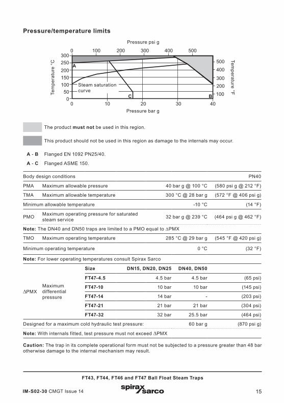
The product must not be used in this region.
This product should not be used in this region as damage to the internals may occur.
A - B Flanged EN 1092 PN25/40.
A - C Flanged ASME 150.
Body design conditions PN40
PMA Maximum allowable pressure 40 bar g @ 100 °C (580 psi g @ 212 °F)
TMA Maximum allowable temperature 300 °C @ 28 bar g (572 °F @ 406 psi g)
Minimum allowable temperature -10 °C (14 °F)
PMO Maximum operating pressure for saturated steam service 32 bar g @ 239 °C (464 psi g @ 462 °F)
Note: The DN40 and DN50 traps are limited to a PMO equal to ∆PMX
TMO Maximum operating temperature 285 °C @ 29 bar g (545 °F @ 420 psi g)
Minimum operating temperature 0 °C (32 °F)
Note: For lower operating temperatures consult Spirax Sarco
DPMXMaximum differential pressure
Size DN15, DN20, DN25 DN40, DN50
FT47-4.5 4.5 bar 4.5 bar (65 psi)
FT47-10 10 bar 10 bar (145 psi)
FT47-14 14 bar - (203 psi)
FT47-21 21 bar 21 bar (304 psi)
FT47-32 32 bar 25.5 bar (464 psi)
Designed for a maximum cold hydraulic test pressure: 60 bar g (870 psi g)
Note: With internals fitted, test pressure must not exceed PMX
Caution: The trap in its complete operational form must not be subjected to a pressure greater than 48 bar otherwise damage to the internal mechanism may result.
B
Steam saturation curve

IM-S02-30 CMGT Issue 1416
FT43, FT44, FT46 and FT47 Ball Float Steam Traps
Note: Before actioning any installation observe the 'Safety information' in Section 1.
Warning Note 1: The FT must be installed with the direction of flow as indicated on the body. Ensuring the float arm is in the horizontal plane so that it rises and falls vertically.
Note 2: It’s recommended that a strainer is fitted upstream of the trap and that sound engineering practice is followed and that the system undergoes regular maintenance to ensure the steam quality is to industry standard.
Note 3: The installation of the trap needs to be carried having selected nuts, bolts and gaskets to adhere to Industry Standards. The nuts and bolts should be tightened to the required torque cited in the Industry Standard.
Referring to the Installation and Maintenance Instructions, name-plate, and Technical Information Sheet, check that the product is suitable for its intended use.
3.1 Check materials, pressure and temperature and their maximum values. If the maximum operating limit of the product is lower than that of the system in which it is being fitted, ensure that a safety device is included in the system to prevent overpressurisation.
3.2 Determine the correct installation situation and direction of fluid flow – please be aware that the flow direction is not the same for all FT trap types or sizes. However the flow direction will be clearly marked on the trap body.
3.3 Remove protection covers from all connections and protective film from all name-plates, where appropriate, before installation on steam or other high temperature applications.
3. Installation
Fig. 5
The nameplate indicates which way is down

IM-S02-30 CMGT Issue 14 17
FT43, FT44, FT46 and FT47 Ball Float Steam Traps
FT
Fig. 6
3.4 The trap must be fitted with the float arm in a horizontal plane so that it rises and falls vertically. Note: The trap can be visually checked for its correct orientation by reading the writing on the body, cover, and name-plate. If installed correctly the writing will be seen to be displayed the correct way up.
3.5 The trap should be fitted below the outlet of the steam system, with a small drop leg immediately proceeding the trap, typically 150 mm (6") see Figure 6. If no drop leg is allowed for then it may be possible (under low load conditions) for steam to flow over the condensate in the bottom of the pipe and reach the trap.

IM-S02-30 CMGT Issue 1418
FT43, FT44, FT46 and FT47 Ball Float Steam Traps
3.7 If the trap is to be situated in an exposed position, it should be either lagged or drained by a separate small thermostatic trap such as the Spirax Sarco No.8, or Bydrain.
3.8 Always fit a non-return (check) valve downstream of any steam trap which discharges into condensate return lines where back pressure is experienced. This is not commonly caused by a rising condensate line. The check valve will prevent the steam space flooding when the inlet pressure is reduced or the steam is shut off.
Fig. 7 Slow speed cylinder drainage with system unit
Air vent
Float trap
Sight glass
Condensate out
Strainer
Air bottle
Cylinder
3.6 Float traps should be fitted as close to the outlet of the plant to be drained as possible otherwise the trap can steam lock. Steam locking occurs when the pipe between the condensate outlet and the steam trap fills with steam and prevents condensate from reaching the trap. This can lead to the system waterlogging which will affect plant efficiency. It is very similar to the air locking experienced in water systems.The most common application where steam locking is a risk is on rotating cylinders and other applications where condensate is removed via a dip tube or siphon pipe. Steam locking can easily be prevented by fitting the trap with a combined thermostatic air vent and an adjustable needle valve (SLR), Figure 7 shows an FT-C trap fitted on a slow speed cylinder.The adjustable needle valve (SLR) is opened by turning the spindle anticlockwise. The standard factory setting is ½ turn which equates to an approximate steam 'bypass' of 22 kg/h @ 10 bar.Site adjustment of the adjustable needle valve can be achieved by turning anticlockwise to increase the bypass flow, and clockwise to reduce the flow.When draining from a high speed cylinder application, there is need for large amounts of blow-through steam to assist the flow of condensate out of the cylinder via the siphon tube. In such cases the adjustable needle valve cannot handle such large amounts and an external bypass with an adjustable needle valve is required. See Figure 8.

IM-S02-30 CMGT Issue 14 19
FT43, FT44, FT46 and FT47 Ball Float Steam Traps
Fig. 8 High speed cylinder with float trap and parallel blow-through valve
Rotating cylinder
Float trap withexternal bypass
Steam in
Rotary joint with flexible couplings
Condensate out
After installation or maintenance ensure that the system is fully functioning. Carry out tests on any alarms or protective devices.
The float trap is a continuous trap, removing condensate the instant it forms. On start-up, the thermostatic air vent allows air to bypass the main valve preventing the system air binding. Hot condensate will close the air vent tightly, but as soon as it enters the main chamber of the trap, the float rises and the lever mechanism attached to it opens the main valve - keeping the system drained of condensate at all times. When the steam arrives, the float drops and closes the main valve. Float traps are renown for their high start-up load handling capability, clean tight shut-off and resistance to waterhammer and vibration.
4. Commissioning
5. Operation
3.9 Ensure adequate space is left to remove the cover from the body for maintenance – the maximum withdrawal to remove the cover is 200 mm (8").
Note: If the trap is to discharge to atmosphere ensure it is to a safe place, the discharging fluid may be at a temperature of 100 °C (212 °F).

IM-S02-30 CMGT Issue 1420
FT43, FT44, FT46 and FT47 Ball Float Steam Traps
6.1 FT43, FT44, FT46 and FT47 (DN15 to DN50)
Dowel
Steam lockrelease assembly19 + 21
2
2 3
20
WarningThe cover gasket contains a thin stainless steel support ring which may cause physical injury if not handled and disposed of carefully.
6. Maintenance and spare parts
18 17Bimetallic air vent assembly

IM-S02-30 CMGT Issue 14 21
FT43, FT44, FT46 and FT47 Ball Float Steam Traps
Table 1 Recommended tightening torques
Item No. Size or
mm N m (lbf ft)
2*
DN15, DN20, DN25
17 A/F M10 x 30 29 - 33 (19 - 24)
DN40 24 A/F M12 x 60 60 - 66 (44 - 48)
DN50 24 A/F M16 x 70 80 - 88 (58 - 65)
5DN15, DN20, DN25
50 - 55 (37 - 40)
7
DN15, DN20, DN25
M5 x 20 2.5 - 2.8 (1.8 - 2.1)
DN40 10 A/F M6 x 20 10 - 12 (7.0 - 9.0)
DN50 13 A/F M8 x 20 20 - 24 (15 - 17)
17 17 A/F 50 - 55 (37 - 40)
19* 22 A/F 40 - 45 (29 - 33)
FT44 only*
2DN15, DN20, DN25
17 A/F M10 x 30 19 - 22 (14 - 16)
19 22 A/F 50 - 55 (37 - 40)
65 10 7 811 9
266 5 7812
Main valve assembly with float (DN15, DN20 and DN25)
Main valve assembly(DN40 and DN50)
Capsule air vent assembly17
18
Notes:- Before actioning any
maintenance programme observe the 'Safety information' in Section 1.
- The FT43 is not normally provided with a bimetallic air vent due to its PN16 rating. This arrangement can be made available on request.
IM-S02-30 CMGT Issue 1422
FT43, FT44, FT46 and FT47 Ball Float Steam Traps
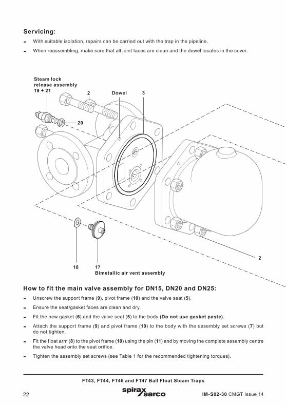
Servicing:- With suitable isolation, repairs can be carried out with the trap in the pipeline.
- When reassembling, make sure that all joint faces are clean and the dowel locates in the cover.
Dowel
Steam lockrelease assembly19 + 21
2
2 3
20
18
How to fit the main valve assembly for DN15, DN20 and DN25:- Unscrew the support frame (9), pivot frame (10) and the valve seat (5).
- Ensure the seat/gasket faces are clean and dry.
- Fit the new gasket (6) and the valve seat (5) to the body (Do not use gasket paste).
- Attach the support frame (9) and pivot frame (10) to the body with the assembly set screws (7) but do not tighten.
- Fit the float arm (8) to the pivot frame (10) using the pin (11) and by moving the complete assembly centre the valve head onto the seat orifice.
- Tighten the assembly set screws (see Table 1 for the recommended tightening torques).
17Bimetallic air vent assembly

IM-S02-30 CMGT Issue 14 23
FT43, FT44, FT46 and FT47 Ball Float Steam Traps
65 10 7 811 9
266 5 7812
Main valve assembly with float (DN15, DN20 and DN25)
Main valve assembly(DN40 and DN50)
Capsule air vent assembly17
18
How to fit the main valve assembly for DN40 and DN50:- Unscrew the 4 bolts or nuts (7).
- Remove the main valve assembly (5) and gasket (6).
- Ensure the gasket faces are clean and dry.
- Fit the new gasket (6) and the main valve assembly (5), including the baffle plate.
- Tighten the bolts or nuts (7) evenly (see Table 1 for recommended tightening torques).
How to fit the capsule air vent assembly for DN15 to DN100:- Remove the spring clip, capsule, spacer plate,
unscrew the seat and remove the frame (17) and gasket (18).
- Ensure the gasket faces are clean and dry.
- Fit the new gasket (18), the frame and seat (17) and tighten to the recommended torque (see Table 1).
- Assemble the new spacer plate, capsule and clip.
How to fit the bimetallic air vent assembly for DN15 to DN100:- Unscrew and remove the element assembly (17)
and gasket (18).
- Ensure the gasket faces are clean and dry.
- Fit the new gasket (18) and element assembly (17) and tighten to the recommended torque (see Table 1).

IM-S02-30 CMGT Issue 1424
FT43, FT44, FT46 and FT47 Ball Float Steam Traps
Spare partsThe spare parts available are shown in heavy outline. Parts drawn in a grey line are not supplied as spares.
Dowel
Steam lockrelease assembly19 + 21
2
2 3
20
18 17Bimetallic air vent assembly

IM-S02-30 CMGT Issue 14 25
FT43, FT44, FT46 and FT47 Ball Float Steam Traps
Available sparesMain valve assembly with float (DN15, DN20 and DN25) (specify horizontal or vertical traps) 5, 6, 7, 8, 9, 10, 11
Main valve assembly with erosion deflector (DN40 and 50) (specify horizontal or vertical trap) 5, 6, 7, 12, 26
Ball float and lever (DN40 and DN50) 8
Air vent assembly Bimetallic air vent assembly/Capsule air vent assembly 17, 18
Steam lock release and capsule air vent assembly 17, 18, 19, 20, 21
Complete set of gaskets (packet of 3 sets) 3, 6, 18, 20
How to order sparesAlways order spares by using the description given in the column headed 'Available spares' and state the size, type of trap, connection: horizontal or vertical and pressure range.
Note: When ordering a spare air vent Assembly, please specify whether you require a bimetallic or capsule air vent assembly.
Example: 1 - Capsule air vent assembly for a Spirax Sarco DN20 FT46-4.5 ball float steam trap, with horizontal connectors.
65 10 7 811 9
266 5 7812
Main valve assembly with float (DN15, DN20 and DN25)
Main valve assembly(DN40 and DN50)
Capsule air vent assembly17
18

IM-S02-30 CMGT Issue 1426
FT43, FT44, FT46 and FT47 Ball Float Steam Traps
Dowel
Air vent assembly
17
3 28
Main valve assembly
18
6.2 FT43 and FT44 (DN80 and DN100)Notes:- Before actioning any maintenance programme observe the 'Safety information' in Section 1.
- The FT43 is not normally provided with a bimetallic air vent due to its PN16 rating. This arrangement can be made available on request.
WarningThe cover gasket contains a thin stainless steel support ring which may cause physical injury if not handled and disposed of carefully.
12 7 26 5 76
18 17Bimetallic air ventassembly

IM-S02-30 CMGT Issue 14 27
FT43, FT44, FT46 and FT47 Ball Float Steam Traps
Table 2 Recommended tightening torques
Item No. or mm N m (lbf ft)
2FT43 24 A/F M16 x 45
80 - 88 (58 - 65)FT44 24 A/F M16 x 50
7 13 A/F M8 x 20 20 - 24 (15 - 17)
17 17 A/F 50 - 55 (37 - 40)
Unscrew element assembly- Remove the cover nuts (2) and cover.
- Undo the 4 main valve assembly nuts (7).
- Remove the main valve assembly (5) and gasket (6).
- Ensure gasket faces are clean and dry.
- Fit new gasket (6) and main valve assembly (5).
- Tighten nuts (7) evenly (see Table 2 for the recommended tightening torques).
- Re-use or replace the ball float (8) as required.
- Replace cover gasket (3) ensuring the gasket face has been cleaned.
- Replace the cover, ensuring the dowel is located correctly.
- Retighten the cover nuts (2) evenly (see Table 2 for the recommended tightening torques).
How to fit the capsule air vent assembly:- Remove the spring clip, capsule, spacer plate, unscrew the seat and remove the frame (17) and
gasket (18).
- Ensure the gasket faces are clean and dry.
- Fit the new gasket (18), frame and seat (17) and tighten evenly (see Table 2 for the recommended tightening torques).
- Assemble new spacer plate, capsule and clip.
How to fit the bimetallic air vent assembly for DN15 to DN100:- Unscrew and remove the element assembly (17) and gasket (18).
- Ensure the gasket faces are clean and dry.
- Fit the new gasket (18) and element assembly (17) and tighten evenly to the recommended torque (see Table 2).

IM-S02-30 CMGT Issue 1428
FT43, FT44, FT46 and FT47 Ball Float Steam Traps
Dowel
Air vent assembly
17
3 28
Main valve assembly
18
18
12 7 26 5 76
Spare partsThe spare parts available are shown in heavy outline. Parts drawn in a grey line are not supplied as spares.
Available sparesMain valve assembly 5, 6, 7, 12, 26Ball float and lever 8Air vent assembly Bimetallic air vent assembly/Capsule air vent assembly 17, 18Set of all gaskets (packet of 3 sets) 3, 6, 18
Note: For a complete overhaul 2 off of each spare are required.
How to order sparesAlways order spare parts by using the description given in the column headed 'Available spares' and state the size, Model No. and pressure rating of the trap.Example: 1 - Main valve assembly for a DN80 Spirax Sarco FT43-10TV ball float steam trap.
17Bimetallic air ventassembly

IM-S02-30 CMGT Issue 14 29
FT43, FT44, FT46 and FT47 Ball Float Steam Traps
6.3 FT mechanisms (DN40 only)Baffle arrangement used on FT43, FT44, FT46 and FT47 (horizontal only)In line with our policy of continuous product improvement, we have found it beneficial to add a baffle plate over the inlet port.This eliminates any risk of flow from the inlet port affecting the correct operation of the float. When fitting the mechanism, assemble the baffle plate supplied under the mechanism retaining bolts.
The correct positioning is shown below.
6.4 FT mechanisms (DN50 only)Baffle arrangement used on FT43, FT44, FT46 and FT47 (horizontal only)When fitting the mechanism, assemble as follows:
1. Remove two uppermost studs and replace with the longer studs provided.
2. Assemble the mechanism over the four studs.
3. Place the spacer collars then baffle plate over the longer studs so that the collars rest on the back of the square flange.
4. Replace the nuts and tighten as normal.
The correct assembly and positioning is shown below.
Inletbaffle
Inlet port
Inlet port
Inlet port
Spacer
Inletport
Inlet baffle
Longerstuds
Inletbaffle
Inlet baffle
Fig. 9
Fig. 10

IM-S02-30 CMGT Issue 1430
FT43, FT44, FT46 and FT47 Ball Float Steam Traps

IM-S02-30 CMGT Issue 14 31
FT43, FT44, FT46 and FT47 Ball Float Steam Traps

IM-S02-30 CMGT Issue 1432
FT43, FT44, FT46 and FT47 Ball Float Steam Traps