ftc 2201 red light controller - flash technology · mkr 370 ac power consumption: mkr 370 ac ir...
TRANSCRIPT

Flash Technology, 332 Nichol Mill Lane, Franklin, TN 37067www.spx.com/en/flash-technology
(615) 261-2000
FTC 2201 Red Light ControllerReference Manual
Part Number F7903667SERIAL NUMBER

ii Revision 9 – 7-16-2014 FTC 2201
Front Matter
Abstract
This manual contains information and instructions for installing, operating and maintainingthe FTC 2201 Red Light Controller.
Copyright
Copyright© 2014, Flash Technology®, Franklin, TN, 37067, U.S.A.
All rights reserved. Reproduction or use of any portion of this manual is prohibited withoutexpress written permission from Flash Technology and/or its licenser.
Trademark Acknowledgements
Flash Technology® is a registered trademark name.
All trademarks and product names mentioned are properties of their respective companiesand are recognized and acknowledged as such by Flash Technology.
Applicable Specifications
This equipment meets or exceeds requirements for an FAA Type L-864.
Disclaimer
While every effort has been made to ensure that the information in this manual is complete,accurate and up-to-date, Flash Technology assumes no liability for damages resulting fromany errors or omissions in this manual, or from the use of the information contained herein.Flash Technology reserves the right to revise this manual without obligation to notify anyperson or organization of the revision.
In no event will Flash Technology be liable for direct, indirect, special, incidental, orconsequential damages arising out of the use of or the inability to use this manual.
Warranty
Flash Technology warrants all controller components, under normal operating conditions, for1 year. LED Lighting components are warranted for 5 years.
Parts Replacement
The use of parts or components, in this equipment, not manufactured or supplied by FlashTechnology voids the warranty and invalidates the third party testing laboratory certificationwhich ensures compliance with FAA Advisory Circulars 150/5345-43G, 150/5345-53D, andEngineering Brief No. 67D. The certification is valid as long as the system is maintained inaccordance with FAA guidelines (FR doc. 04-13718 filed 6-16-04).

FTC 2201 Revision 9 – 7-16-2014 iii
Personnel Hazard Warning
Dangerous Voltages
Dangerous line voltages reside in certain locations in this equipment. Also, this equipmentmay generate dangerous voltages. Although Flash Technology has incorporated everypractical safety precaution, exercise extreme caution at all times when you expose circuitsand components, and when you operate, maintain, or service this equipment.
Avoid Touching Live Circuits
Avoid touching any component or any part of the circuitry while the equipment is operating.Do not change components or make adjustments inside the equipment with power on.
Do Not Depend on Interlocks
Never depend on interlocks alone to remove unsafe voltages. Always check circuits with avoltmeter after turning the circuit breakers off. Under no circumstances remove or alter thewiring or interlock switches.

iv Revision 9 – 7-16-2014 FTC 2201
Table of Contents
Front Matter .............................................................................................................................. iiApplicable Specifications ..................................................................................................... iiDisclaimer ............................................................................................................................. iiWarranty ............................................................................................................................... iiParts Replacement................................................................................................................. ii
Personnel Hazard Warning ...................................................................................................... iiiTable of Contents..................................................................................................................... ivList of Figures ........................................................................................................................... vList of Tables ............................................................................................................................ vSection 1 – Introduction............................................................................................................ 1
FTC 2201 Controller............................................................................................................. 1Specifications........................................................................................................................ 1Operation............................................................................................................................... 2
Controller (PCB1)............................................................................................................. 2Beacon / Marker Connection ............................................................................................ 2
Mode Select Switch .............................................................................................................. 2Manual Override Operation .............................................................................................. 2Normal LED Operation..................................................................................................... 2Photocell ........................................................................................................................... 2
FH 370r ................................................................................................................................. 6MKR 370 .................................................................................................................................. 8Section 2 – Outline, Mounting and Installation ........................................................................ 9
Unpacking ............................................................................................................................. 9Tools ..................................................................................................................................... 9Mounting............................................................................................................................... 9
Controller .......................................................................................................................... 9Photocell ........................................................................................................................... 9Antenna Mounting ............................................................................................................ 9FH 370r AC Beacon (L-864) .......................................................................................... 10MKR 370 AC (L-810) .................................................................................................... 10
Installation Wiring .............................................................................................................. 10Wiring ............................................................................................................................. 10Lightning Protection ....................................................................................................... 11Securing the Cable .......................................................................................................... 11
Installation Checklist .......................................................................................................... 12Checkout Procedure ............................................................................................................ 13
Using the Photocell ......................................................................................................... 13Using the Mode Override Switch ................................................................................... 13GPS (if installed)............................................................................................................. 13
Section 3 – Maintenance and Troubleshooting....................................................................... 25Safety .................................................................................................................................. 25Maintenance........................................................................................................................ 25Preventive Maintenance...................................................................................................... 25Storage ................................................................................................................................ 25
RFI Problems .................................................................................................................. 25

FTC 2201 Revision 9 – 7-16-2014 v
Troubleshooting .................................................................................................................. 25FTC 2201 ........................................................................................................................ 25Photocell ......................................................................................................................... 26
Component Removal and Replacement.............................................................................. 27FTC 2201 ........................................................................................................................ 27FH 370r AC / FH 370r IR AC ........................................................................................ 27MKR 370 (L-810 Marker) .............................................................................................. 28
Section 4 – Major Replaceable Parts ...................................................................................... 29Customer Service ................................................................................................................ 29Ordering Parts ..................................................................................................................... 29FTC 2201 Controller Parts.................................................................................................. 29FH 370r AC LED Beacon Parts.......................................................................................... 29Photocell ............................................................................................................................. 29
Return Material Authorization (RMA) Policy........................................................................ 32
List of Figures
Figure 1-1 – PCB1 Controller Board ........................................................................................ 4Figure 1-2 – PCB1 Controller Board with GPS........................................................................ 5Figure 1-3 – FH 370r AC.......................................................................................................... 6Figure 1-4 – FH 370r AC Base (Internal)................................................................................. 7Figure 1-5 – MKR 370.............................................................................................................. 8Figure 2-1 – FTC 2201 Controller Mounting and Outline ..................................................... 14Figure 2-2 – Photocell Sensor Mounting and Outline ............................................................ 15Figure 2-3 – FH 370r LED Beacon Base Outline................................................................... 16Figure 2-4 – MKR 370 Mounting and Outline ....................................................................... 17Figure 2-5 – FTC 2201 Typical A0 Installation Wiring ......................................................... 18Figure 2-6 – FTC 2201 Typical A1 Installation Wiring ......................................................... 19Figure 2-7 – FTC 2201 Typical A1 (4 Conductor) Installation Wiring ................................. 20Figure 2-8 – FTC 2201 Recommended Alarm Wiring........................................................... 22Figure 2-9 – FH 370r AC Internal Wiring .............................................................................. 23Figure 2-10 – FH 370r IR AC Internal Wiring ....................................................................... 24Figure 4-1 – FH 370r AC Component Locations ................................................................... 30
List of Tables
Table 1-1 – PCB1 Jumpers, Switches, Connectors and LEDs ................................................. 3Table 3-1 – Major Troubleshooting Symptoms...................................................................... 27Table 4-1 – FTC 2201 Major Replaceable Parts .................................................................... 29Table 4-2 – FH 370r AC Replaceable Parts............................................................................ 30Figure 4-2 – FH 370r IR AC Component Locations .............................................................. 31Table 4-3 – FH 370r IR AC Replaceable Parts....................................................................... 31


FTC 2201 Revision 9 – 7-16-2014 1
Section 1 – Introduction
FTC 2201 ControllerThe FTC 2201 Controller operates one FH370r AC (standard) or FH 370r IR AC(Infrared) L-864 LED Beacon and / or upto four MKR 370 AC or MKR 370 AC IRL-810 LED markers.* The FTC 2201Controller directs beacon flashing andreports light operating status. It allowsphotocell or manual override modecontrol.
The FTC 2201 Controller with GPS option
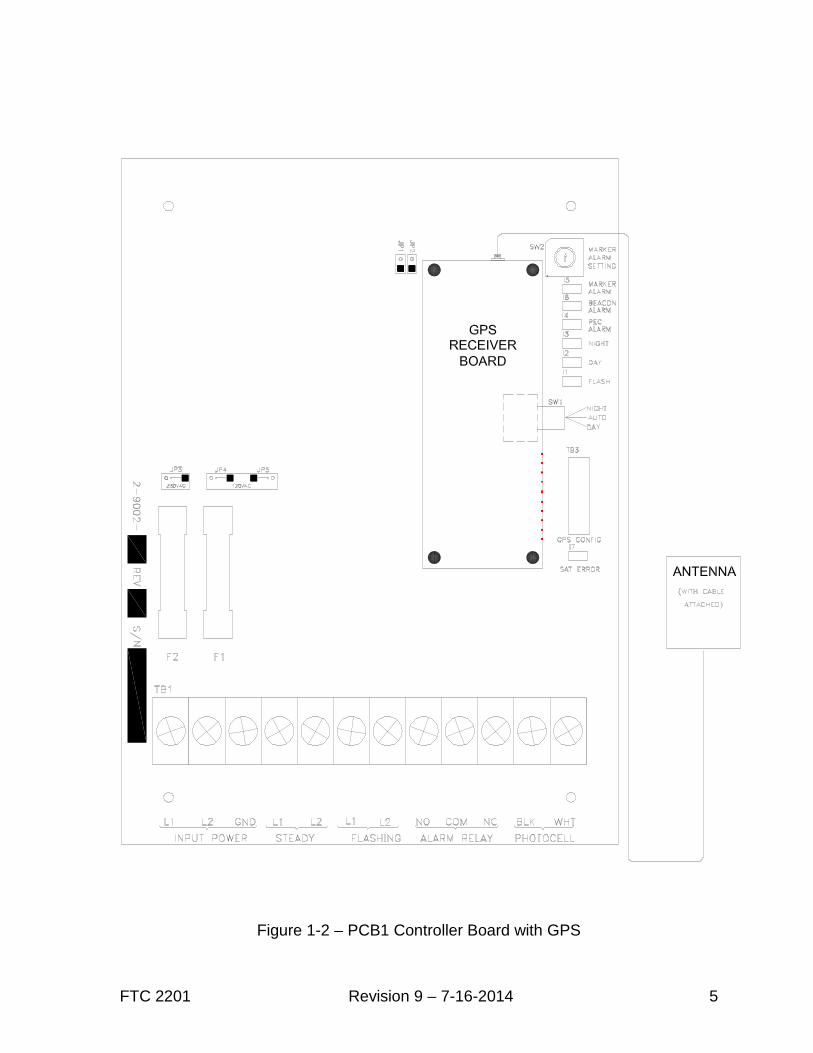
permits synchronization of multiple FTC2201 Controllers with no separation limitbetween units and no additionalinterconnect wiring required. Each FTC2201 Controller must use a PCB1Controller board with a GPS board and anantenna to obtain a GPS sync signal. A‘SAT ERROR’ LED indicates status of theGPS synchronization. Otherwise,operation of the Controller is unchanged.
Specifications
Parameter Specification
FTC 2201 ControllerPhysical Dimensions (H x W x Depth, Wt)(See Figure 2-1 for mounting dimensions)
Operating Temperature RangeAC Line Voltage
Power Consumption:Alarm Relay Contact Rating
9.62 x 7.5 x 4.74 in, 4 lbs /244 x 191 x 121 mm, 1.81 kg-40 to +85 degrees Centigrade120/240V AC ±10% 60 Hz ±5% single phase230V AC ±10% 50 Hz ±5% single phase4 Watts5 Amp @ 250V AC, Isolated contacts
L-864 FH 370r AC / FH 370r IR AC LED BeaconPhysical Dimensions (H x Diameter, Wt)Flash Intensity (nominal)Flash RateBeam Spread
FH 370r AC LED BeaconPower Consumption:
FH 370r IR AC LED BeaconPower Consumption:
7.5 x 15.75 in, 26.3 lbs / 190.5 x 400, 11.9 kg.Night (Red) 2,000 ± 25% ECD20 fpmHorizontal: 360º / Vertical: 3º Min.
14 Watts
23 WattsL-810 MKR 370 AC / MKR 370 AC IR
Physical Dimensions (H x Diameter, Wt):Intensity (nominal):Beam Spread:
MKR 370 ACPower Consumption:
MKR 370 AC IRPower Consumption:
8 x 2 in, 1.0 lbs / 203.2 x 50.8 mm, 0.45 kgNight (Red) 32.5 ± 25% ECDHorizontal: 360º / Vertical: 10º
2.7 Watts (per fixture)
4.6 Watts (per fixture)
*When supplied with an FH 370r AC or MKR 370 AC, the FTC 2201 is designed for operationat 120V AC 60 Hz only. When supplied with an FH 370r IR AC or MKR 370 AC IR, the systemmay be specified for operation at 120/240V AC 60 Hz or 230V AC 50 Hz. FTC 2201 systemsoperating at 230 or 240V AC are limited to two (2) MKR 370 AC IR fixtures. FTC 2201controller versions are available to support legacy lighting components and configurations.See FTC 2201 Reference Manual Rev. 7 for information regarding legacy lighting equipment.

2 Revision 9 – 7-16-2014 FTC 2201
OperationThe controller begins operation as soon asmain power is applied.
Controller (PCB1)
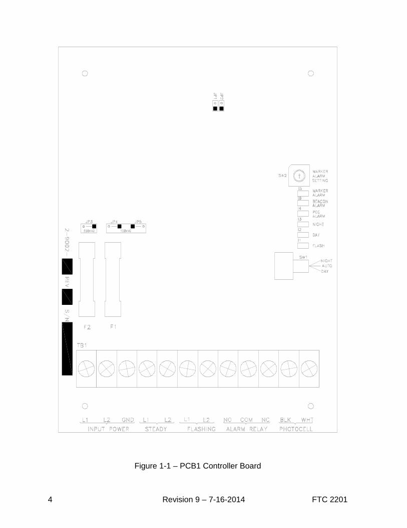
PCB1 has jumpers, switches, connectors,and LEDs whose functions are describedin Table 1-1. Figure 1-1 provides apictorial of the standard PCB1 ControllerBoard. Figure 1-2 provides a pictorial ofthe PCB1 Controller Board with GPSsync.
Each PCB1 configuration must beprogrammed at the factory for a specificapplication. When ordering, be sure tospecify the lighting requirements for yourapplication.
Beacon / Marker Connection
The FTC 2201 controller has twoconnections for beacons and markerslabeled “Steady” and “Flashing”. If thecontroller is being used to flash a beaconand run steady marker lights, the beacon isconnected to L1 and L2 of the “Flashing”output (TB1-6 & 7) and the markers areconnected to L1 and L2 of the “Steady”output (TB1-4 & 5). If the FTC 2201controller is being used to flash L-810markers only, they will be connected tothe “Flashing” output (TB1-6 & 7).
Mode Select SwitchThe DAY/AUTO/NIGHT manual overridemode switch, which controls day, night orautomatic operation (directed by thephotocell), is located on the right center ofPCB1. For normal operation, the switchshould be placed in the AUTO position.
Manual Override Operation
Select the desired mode of operation(DAY or NIGHT) by using theDAY/AUTO/NIGHT switch as shown inFigures 1-1 and 1-2.
The DAY or NIGHT position of theswitch overrides photocell control (Autoposition). The override does NOTtimeout.
Note: The Day and Night positions ofthe switch are intended for short termoperation of the unit. The 19 hourphotocell alarm timer is still active evenif the unit is manually placed in Day orNight mode.
Normal LED Operation
The LEDs on the PCB1 Controller Boardshould operate as described in thefollowing list with the DAY/AUTO/NIGHT switch in AUTO:
• The ALARM LEDs are not illuminated.
• The DAY or NIGHT mode LED isilluminated according to the ambientlighting conditions.
• The FLASH LED should be flashing ifthe unit is in NIGHT mode.
Photocell
The photocell changes resistance asambient light changes from day to night orfrom night to day. The controller board(PCB1) converts the changes into thenecessary circuit operation for day or nightoperation.

FTC 2201 Revision 9 – 7-16-2014 3
Table 1-1 – PCB1 Jumpers, Switches, Connectors and LEDs
JP1
Installed for all 120V AC systems.
Systems with Infrared (IR) beacons or markers: Installed for operation at 230VAC; removed for operation at 240V AC.
JP2
Systems with Infrared (IR) beacons or markers: Installed for operation at 120 &240V AC; removed for operation at 230V AC.
Legacy systems with Incandescent markers: Refer to FTC 2201 manual Rev. 7.
JP3Systems with Infrared (IR) beacons or markers: Installed for operation at230/240V AC. (Not applicable to systems with FH 370r AC or MKR 370 AC.)
JP4 & JP5Installed for operation at 120V AC. (Required for systems with FH 370r AC orMKR 370 AC.)
Manual OverrideSwitch SW1
Auto: Normal operating positionDay: Manual override to DAY modeNight: Manual override to NIGHT mode
LED I1Flashing = Syncs with NIGHT mode flash of flashing circuit.Steady Off = No power or DAY mode.
LED I2 DAY - On = DAY mode; LED will blink if unit is in Manual Override to DAY mode.
LED I3NIGHT - On = NIGHT mode; LED will blink if unit is in Manual Override toNIGHT mode.
LED I4PEC Alarm - On = Photocell alarm. The unit failed to transition modes within 19hours via the photocell input.
LED I5 Marker Alarm - On = Alarm condition exists on “Steady” output (TB1- 4 & 5).
LED I6Beacon Alarm - On = Alarm condition exists on “Flashing” output (TB1-6 & 7).(Beacon Alarm or Flashing Marker Alarm depending on installation.)
LED I7Satellite Error – On = Signals from fewer than three satellites are being received.(GPS enabled units only.)
SW2Marker Alarm Switch - Set to the number of marker bulbs installed to establishalarm condition.
4 Revision 9 – 7-16-2014 FTC 2201
Figure 1-1 – PCB1 Controller Board
FTC 2201 Revision 9 – 7-16-2014 5
Figure 1-2 – PCB1 Controller Board with GPS

6 Revision 9 – 7-16-2014 FTC 2201
FH 370rThe FH 370r AC, shown in Figure 1-3, isdivided into two sections: light engine,and base assembly. The light engine iscomprised of 36 highly efficient red LEDswhich are focused by Fresnel optics toproduce the required output per FAAspecifications for type L-864 beacons. Inthe event service is required, the lightengine is field replaceable as a singleassembly. The FH 370r AC componentlayout is shown in Figure 4-2 and thewiring diagram is shown in Figure 2-9.
The FH 370r IR AC (Infrared) is visuallysimilar to Figure 1-3. It incorporates allfeatures of the FH 370r AC and adds 12infrared LEDs. The addition of IR ensuresvisibility of the obstruction to pilots aidedby NVG (night vision goggles). Thecombination of standard Red (620nm)LEDs and IR (850nm) LEDs ensuresmaximum visibility to pilots in allcircumstances. The FH 370r IR ACcomponent layout is shown in Figure 4-3and the wiring diagram is shown in Figure2-10.
Figure 1-4 provides an overhead view ofthe FH 370r AC base assembly. Locatedin the base is a terminal block for inputpower connections and a power supplythat converts the input AC voltage to theappropriate DC output. Mounted on theterminal block are two surge suppressionunits. A window in the top right corner ofeach surge suppression unit indicates itsstatus. During normal operation, thewindow will appear dark. If the surgesuppressor fails, the window will turn red;indicating that the surge suppression unitsshould be replaced.
Note: FH 370r AC shown. FH 370r IRAC similar.
Figure 1-3 – FH 370r AC

FTC 2201 Revision 9 – 7-16-2014 7
A voltage selector switch,located on the power supply, ismarked to indicate the powersupply’s input voltageconfiguration (115V or 230V).
FTC 2201 controllers must be configuredfor operation at 120V AC 60 Hz whenconnected to an FH 370r AC. Use a flatblade screwdriver to move the powersupply’s voltage selector switch to the115V position for operation with the FTC2201 controller.
The FTC 2201 may be specified foroperation at 120, 230 or 240V AC whenconnected to an FH 370r IR AC. Verifythat the voltage selector switch is set tomatch the controller’s input voltage beforepowering the system on.
Important! FTC 2201 controllers, whenused with an FH 370r AC, areconfigured for operation at 120V AC, 60HZ. The power supply, located in thebase assembly of the FH 370r AC, mustbe set to 115V before applying power tothe system.
FTC 2201 controllers may beconfigured for operation at 120, 230 or240V AC when connected to an FH370r IR AC. Verify that the powersupply, located in the base assembly ofthe FH 370r IR AC is set to match thesupply voltage to the FTC 2201 beforepowering the system on. The voltageselector switch should be set to 230Vfor operation at 240V AC.
Note: FH 370r AC shown. FH 370r IR AC similar.
Figure 1-4 – FH 370r AC Base (Internal)
Input PowerConnections
SurgeSuppressors
TerminalBlock
Assembly
Power Supply
VoltageSelectorSwitch

8 Revision 9 – 7-16-2014 FTC 2201
MKR 370The MKR 370 AC, shown in Figure 1-5, isan L-810 LED marker. The innovativedesign combines three highly efficientLED’s and Fresnel optics into a compactcast aluminum base which is easy toinstall; requiring minimal hardware.
The MKR 370 AC IR (Infrared), which isvisually identical to the MKR 370 AC,adds three IR LEDs. The addition of IR
ensures visibility of the obstruction topilots aided by NVG. The combination ofstandard Red (620nm) LEDs and IR(850nm) LEDs ensures maximumvisibility to pilots in all circumstances.
A mounting diagram for the MKR 370 isprovided in Figure 2-4. Completeinstallation diagrams and instructions areprovided with the marker kit.
Note: Refer to “MKR 370 Wiring Instructions” (Part # 7119001) for specific informationregarding cable connection to the MKR 370.
Figure 1-5 – MKR 370

FTC 2201 Revision 9 – 7-16-2014 9
Section 2 – Outline, Mounting and Installation
UnpackingInspect shipping cartons for signs ofdamage before opening. Check packagecontents against the packing list andinspect each item for visible damage.Promptly report damage claims to thefreight handler.
ToolsFlash Technology suggests the followingtools for installation and maintenance:• 1/8” non-flared flat blade screw driver• 9 or 12 inch, flat blade #2 screwdriver• #2 Phillips® head screwdriver• Set of combination wrenches• Long-nose pliers• Assorted nut driver handles: 1/4”,5/16”, 3/8” recommended• Digital volt-ohm meter• Wire strippers• Level
Mounting
Controller
A quick-release latch secures theenclosure’s door. Release the latch andopen the door for internal access.
Outline and mounting dimensions for thecontroller are shown in Figure 2-1.
Locate the FTC 2201 Controller in an areawith restricted access. You can place thecontroller anywhere within 400 feet of themost distant beacon or marker. Consultwith the factory if a greater distance isnecessary.
Use the following guidelines for mountingthe controller:
Ensure that adequate space existsaround the equipment for accessduring installation, maintenance andservicing.
Allow space for air flow around thecontroller.
Note: Flash Technology does notfurnish mounting hardware unless it isordered as part of an installation kit.
Photocell
The photocell is supplied with pigtails forconnection to the FTC 2201. The standardphotocell (Part # 1855001) is suppliedwith 20’ of cable. Photocells with cablelengths up to 75’ are available.
The photocell may be located any practicaldistance from the FTC 2201. The cablemay be spliced to provide additionallength. The recommended minimum wiregauge is #16 AWG if additional length isnecessary.
Mounting and outline dimensions for thephotocell are shown in Figure 2-2. Usethe following guidelines for the photocell:
Locate the photocell where it has anunobstructed view of the polar sky.
It must not view direct or reflectedartificial light.
The photocell may be supporteddirectly by electrical conduit.
Mount the photocell on the top end ofa vertical length of conduit to preventwater from entering and damaging theunit.
Antenna Mounting
(Units with GPS only)
Mount the Antenna to the top of anoutdoor structure facing an unobstructedview of the sky. If possible, provide amaterial below it that attracts the antenna’smagnet. Do not place any materials abovethe antenna (including materials used tosecure it) that block RF Energy. An

10 Revision 9 – 7-16-2014 FTC 2201
optional antenna with extended separationis available (see parts list).
FH 370r AC Beacon (L-864)
Outline and mounting dimensions for theFH 370r are shown in Figure 2-3.
Note: Flash Technology recommendsthe installation of one or more lightningrods near the uppermost lightingfixture(s). The copper lightning rodsshould extend a minimum of 36” abovethe height of the lighting fixture and aminimum of 18” horizontally away fromthe fixture.
The beacon is mounted to the towerpedestal utilizing 1/2” galvanized (FlashTechnology part 5991740) or stainlesssteel hardware. Mounting holes areprovided on the beacon base as shown inFigure 2-3. These mounting holes willalign with most tower pedestals. Thebeacon must be installed level to maintainlight output in accordance with FAArequirements.
Important! Ensure the flashhead isgrounded to the tower.
MKR 370 AC (L-810)
Outline and mounting dimensions for theMKR 370 are shown in Figure 2-4.
Note: MKR 370 installation diagramsare included with the marker kit and arenot part of this document.
Installation Wiring
Wiring
This manual may not contain all theinformation about installation wiringrequired for your installation.
Note: If installation drawings preparedspecifically for your site disagree withinformation provided in this manual, thesite installation drawings should takeprecedence. Consult any site-specificinstallation wiring diagram supplied withyour equipment.
Flash Technology wiring diagramsdefine only minimum requirementsrecommended for satisfactoryequipment operation. It is theresponsibility of the installer to complywith all applicable electrical codes.
All installation wiring should have aninsulation rating of 600 volts. Wire sizefor the lights on each wire run iscalculated from the number of lightingfixtures and the length of the wire on thatrun. Wire for the lights should be sized sothat the voltage drop does not exceed 3%due to wire resistance. Assume 7.8 VA forthe FH 370r AC and 25.6 VA for the FH370r IR AC beacon. Assume 5 VA foreach MKR 370 AC and 8.5 VA for eachMKR 370 AC IR. Total power required isthe sum of all lights plus 4.5 VAadditional for the FTC 2201 Controller.
Typical installation wiring diagrams forthe FTC 2201 are shown in Figures 2-5through 2-7. Alarm wiringrecommendations are shown in Figure 2-8.
Make electrical connections at thefollowing terminals:
Beacon or Flashing Marker: TB1-6(L1) and TB1-7 (L2, N)
Marker steady: TB1-4 (L1) and TB1-5(L2, N)
Photocell: (control) TB1-11 and TB1-12
Alarm: TB1-8 and TB1-9 (NO) orTB1-9 and TB1-10 (NC).
Note: The alarm relay contacts arelabeled to represent their state with theunit powered on and with no alarmspresent.
To ensure proper alarm monitoring,Flash Technology recommendsmonitoring contacts that are open in analarm condition (TB1-9 and TB1-10).

FTC 2201 Revision 9 – 7-16-2014 11
Lightning Protection
All Flash Technology equipment isdesigned to withstand severe transientover-voltages. However, a lightningarresting system should be installed toprevent eventual damage by lightning.Transient suppressors from line-to-lineand line-to neutral are recommended at theprimary power load center.
Securing the Cable
Flash Technology recommends thefollowing method for securing the beaconand marker cable to a skeletal structure:
1. Run the cable along one of the towerlegs and wrap two full turns of two-inch Scotchrap™ #50 tape, or theequivalent, around the cable and towerleg at regular intervals of about 5 feet(1.5 meters).
2. Wrap three full turns of one-inchScotchrap Filament #890 tape, or theequivalent, over the Scotchrap #50tape.
3. Wrap four full turns of two-inchScotchrap #50 tape, or the equivalent,over the Scotchrap Filament #890 tape.
4. Perform steps 1 through 4 directlyabove and below any tower leg flangesthat the cable may cross. The cableshould be spaced approximately 1 inchfrom the edge of each flange toprovide stress relief from vibration thatmay damage the jacket of the cable. A5 foot service loop should be locatednear the beacon and the controller.

12 Revision 9 – 7-16-2014 FTC 2201
Installation ChecklistUse the following checklist wheninstalling the system:
1. Equipment Damage:Inspect all equipment for damage.
2. Required Equipment:Verify the received equipment againstthe packing list to ensurecompleteness.
3. Consult site installation drawings forplacement, mounting and wiringdetails.
4. Provide a power disconnect switch or acircuit breaker.
5. Check the lightning protection system.
6. Be sure that junction boxes will draincondensation properly.
7. Controller:
Position and mount the controllerallowing adequate clearance toopen the cover.
Ensure that the unit is mountedupright.
Check the internal hardware toensure that all screws are tight.
Ensure that no holes are punchedor drilled on the top surface of theenclosure.
Ensure that air can flow around theenclosure.
8. Photocell:
Locate the photocell where it hasan unobstructed view of the polarsky (north).
It must not view direct or reflectedartificial light.
The photocell should be supporteddirectly by electrical conduit ormounted on the optional Antenna
Mounting Bracket (Kit PN1905355). It should not bemounted underneath the controllerwhere it could be shadowed.
Ensure that the installation iswatertight.
9. GPS Antenna (Units with GPS only):
The GPS antenna must be mountedoutdoors with an unobstructed view ofthe sky.
Note: The GPS antenna can bemounted on the optional AntennaMounting Bracket (Kit PN 1905355).
Complete the following steps beforeapplying power:
10. Examine the installation drawings:
Check for proper incoming servicevoltage. Verify that primary powervoltage is the value stated on theID plate.
The unit is wired according to theinstructions.
Check all electrical connections fortightness.
Check all terminal stripconnections for tightness.
If external alarm detection circuitresponds to closed contacts, ensurethat they are wired to the contactson TB1-8 and TB1-9 (NO) thatclose on alarm.
If external alarm detection circuitresponds to open contacts, ensurethat they are wired to the contactson TB1-9 and TB1-10 (NC) thatopen on alarm.
Protect alarm wiring by usingshielded wires, grounding theshield, and placing wires in aconduit.

FTC 2201 Revision 9 – 7-16-2014 13
The black wire of the photocell isconnected to TB1-11 and the whitewire is connected to TB1-12.
The GPS antenna is connected tothe GPS receiver board (units withGPS only).
After completing all of the precedingsteps, apply power to the unit and performan operational checkout from proceduresin “Checkout Procedure”.
Checkout Procedure
Using the Photocell
Turn the DAY/AUTO/NIGHT Switch toAUTO:
The system is now under photocellcontrol.
Cover the photocell to block it from alllight. With no alarms or errors and after a60 second delay:
The system is now in NIGHT mode.
The beacons should be on and flashing(if installed).
The markers should be on steadily (orflashing depending on configuration).
Uncover the photocell so as to allow lightto strike it, or shine a light on it. With noalarms or errors and after a 60 seconddelay:
The system is now in DAY mode.
The beacons and markers should turnoff.
Using the Mode Override Switch
1. Turn the DAY/AUTO/NIGHT Switchto DAY:
With no alarms or errors:
The system is now in DAY mode.
The beacons and markers shouldturn off.
2. Turn the DAY/AUTO/NIGHT Switchto AUTO:
With no alarms or errors:
The system is now under photocellcontrol.
The beacons and markers shouldbe off during daylight and on atnight.
3. Turn the DAY/AUTO/NIGHT Switchto NIGHT:
With no alarms or errors:
The system is now in NIGHTmode.
The beacons should be on andflashing (if installed).
The markers should be on steadily(or flashing depending onconfiguration).
If the operation is not as described, go toTroubleshooting in Section 3.
GPS (if installed)
Verify that the “SAT Error” LED (I7) isnot lit.

14 Revision 9 – 7-16-2014 FTC 2201
Note: All dimensions are in inches (millimeters).
Figure 2-1 – FTC 2201 Controller Mounting and Outline

FTC 2201 Revision 9 – 7-16-2014 15
Note: All dimensions are in inches (millimeters).
Figure 2-2 – Photocell Sensor Mounting and Outline
2.28 (57.8)
0.13 (3.3)
HEX 1.00(25.4)
3.06(77.7)
1/2" NPT
0.38 (9.5)
2.58 (65.5)

16 Revision 9 – 7-16-2014 FTC 2201
Note: All dimensions are in inches (millimeters).
Figure 2-3 – FH 370r LED Beacon Base Outline
15.75 (400)
7.5 (190.5)

FTC 2201 Revision 9 – 7-16-2014 17
Note: All dimensions are in inches (millimeters).
Figure 2-4 – MKR 370 Mounting and Outline
3/4-14 NPS
0.87(22.1)
0.38(9.7)
0.38(9.7)
1/4-20 UNC
(TYP OF 3)
0.45(11.4)
8.00(203.2)
6.00
(152.4)
2.00
(50.8)
2.06
(52.3)
1.20
(30.48)
1.20
(30.48)
1.26
(32.0)

18 Revision 9 – 7-16-2014 FTC 2201
Note: System Wiring Diagram Notes are provided after Figure 2-7.
Figure 2-5 – FTC 2201 Typical A0 Installation Wiring

FTC 2201 Revision 9 – 7-16-2014 19
Note: System Wiring Diagram Notes are provided after Figure 2-7. MKR 370 connectioninstructions are provided with the marker kit.
Figure 2-6 – FTC 2201 Typical A1 Installation Wiring

20 Revision 9 – 7-16-2014 FTC 2201
Note: System Wiring Diagram Notes are provided after Figure 2-7. MKR 370 connectioninstructions are provided with the marker kit.
Figure 2-7 – FTC 2201 Typical A1 (4 Conductor) Installation Wiring

FTC 2201 Revision 9 – 7-16-2014 21
System Wiring Diagram Notes
1. Mount the FTC 2201 enclosure vertically.
2. AC input power conductor size depends on the service voltage, the distance from thesource and the number of lighting fixtures served. Assume 7.8 VA for the FH 370r ACand 25.6 VA for the FH 370r IR AC beacon. Assume 5 VA for each MKR 370 AC and8.5 VA for each MKR 370 AC IR. Total power required is the sum of all lights plus 4.5VA additional for the FTC 2201 Controller. Also see Note 4.
3. The AC Line Voltage is connected to terminal strip TB1 (L1, L2 & GND).
4. The total line drop, including the input service wiring and branch lines to the L-864beacon and L-810 marker lights, must not exceed 3% of the rated voltage.
5. The FTC 2201 controller PCB must be grounded to the site grounding system.Equipment ground must be included to light fixtures if an approved conduit system is notused, or local code requires.
6. Dry contact alarm output contact rating 5 ampere, 250V AC. Contacts shown in normaloperating state with no alarms or errors.
7. User's alarm circuit not shown.
8. Mount the photocell at the top end of a vertical length of conduit. Face it toward thepolar sky (north). Photocell cable should be two conductors 16 AWG (minimum).
9. Vertical wires, if installed in conduit, must be supported per NEC guidelines and localelectrical codes.
10. The following method is recommended for securing flashhead cables to a skeletalstructure:
A. Wrap 2 full turns of two inch Scotchrap #50 tape, or equivalent alternate, around thecables and tower members at regular intervals along one of the tower legs.
B. Wrap 3 full turns of one inch Scotchrap filament #890 tape, or equivalent alternate,over the Scotchrap #50 tape.
C. Wrap 4 full turns of two inch Scotchrap #50 tape, or equivalent alternate, over thefilament #890 tape. The last two turns should be applied with no tension.
D. Steps A thru C should be performed directly above and below tower leg flanges atintervals of not more than five feet. Do not pull cable tight against flanges or otherhard surface. Allow 1" clearance.
11. Cables and conduit are not included as part of the installation kit, but are required for theinstallation shown and can be purchased with the lighting equipment.
12. Install one or more lightning rods near the uppermost lighting fixture (L-810 or L-864). The copper lightning rod(s) should extend a minimum of 36” above the height ofthe flashhead and a minimum of 18” horizontally away from the flashhead.
13. Refer to Flash Technology supplied marker kit instructions for proper J-box mounting,MKR 370 wiring and installation standards.
14. The FH 370r must be grounded to tower steel using 8 AWG wire minimum.

22 Revision 9 – 7-16-2014 FTC 2201
Figure 2-8 – FTC 2201 Recommended Alarm Wiring
ALARM
130V
AC
MO
V
130V
AC
MO
V
GND
SHIELD
NOTES:1. USE SHIELDED CABLE TO ATTACH FLASH TECHNOLOGY ALARM RELAY CONTACTS TO EXTERNAL EQUIPMENT.2. ATTACH THE SHIELD WIRE TO A GND (GROUND) TERMINAL ON THE FLASH TECHNOLOGY EQUIPMENT AS SHOWN.3. WHEN POSSIBLE, ROUTE ALARM CONTACT WIRING IN METALLIC, GROUNDED CONDUIT.4. FOR ADDITIONAL PROTECTION, ADD MOVs (VARISTORS) FROM EACH ALARM RELAY CONTACT TERMINAL TO A GND
TERMINAL AT THE FLASH TECHNOLOGY POWER CONVERTER.
FLASH TECHNOLOGY ALARM RELAY CONTACTS ARE PROTECTED FROM VOLTAGE TRANSIENTS OF UP TO 1000 VOLTS.HOWEVER, WIRED ALARM CONTACTS CAN BE SUBJECTED TO VOLTAGES GREATER THAN 1000 VOLTS BECAUSE OFLIGHTNING. THE FOLLOWING RECOMMENDATIONS MINIMIZE THE POSSIBILITY OF DAMAGE CAUSED BY HIGH VOLTAGE
CUSTOMER CONNECTION
TO ALARM RELAY CONTACTS
METALLIC CONDUIT
L1 L2

FTC 2201 Revision 9 – 7-16-2014 23
Figure 2-9 – FH 370r AC Internal Wiring

24 Revision 9 – 7-16-2014 FTC 2201
Figure 2-10 – FH 370r IR AC Internal Wiring

FTC 2201 Revision 9 – 7-16-2014 25
Section 3 – Maintenance and Troubleshooting
SafetyWARNING
STOP: Before proceeding, read thePersonnel Hazard Warning on Page iii.
Work safely, as follows:
1. Remove rings and watches beforeopening the equipment.
2. Shut off power to the equipment.
3. Remove the component or connect thetest instruments.
4. Replace the component.
5. Turn on the power and test the system.
6. Turn off the power and disconnect thetest equipment.
MaintenanceThe circuit boards should be kept free ofaccumulated dust. Brush and V ACuum asnecessary.
Important! Do not use compressed air toclean this equipment.
Preventive MaintenanceCarry out the following inspection andcleaning procedures at least once a year:
1. Verify that moisture has not enteredthe equipment through gaskets orseals, or collected inside ascondensation.
2. Verify that all drain holes are clear.
3. Check terminal blocks for corrosion orarcing. Clean or replace anycomponent that shows evidence ofdamage.
4. Check all electrical connections fortightness and verify the absence ofcorrosion or electrical arcing.
5. Clean the outside surface of the lenswith liquid detergent and water. Wipeit gently with a soft cloth.
StorageEquipment should be stored indoors whennot in use. Circuit boards, when notinstalled in the equipment, should be keptin antistatic bags or containers.
RFI Problems
The presence of radio frequencyinterference (RFI) can burn-outcomponents, cause a light to flashintermittently, at the wrong rate, orintensity. RFI can enter the light by anywire to or from the unit. The circuits aredesigned to reject or bypass RFI, but FlashTechnology cannot guarantee completeimmunity beforehand. After installation,you may find it necessary to add externalfilters or use other methods to reduce RFIentering the equipment. To minimizeinterference, ensure proper installation inaccordance with AC 70-7460, Appendix 1,Figure 2.
Troubleshooting
FTC 2201
The most effective troubleshootingprocedure begins with observing thebehavior of the system. This often leadsdirectly to a faulty component or otherabnormal condition.
Table 3-1 provides a list of symptoms thatmay be observed if the system is operatingincorrectly. The column following eachsymptom provides the possible causes inorder of probability.
Note: Always make resistancemeasurements with the primary powerturned off. However, you must makevoltage measurements with power
26 Revision 9 – 7-16-2014 FTC 2201
applied. Thus, for your safety, carry outall preliminary steps such as connectingtest leads or circuit jumpers ordisconnecting existing circuitconnections with the power off.
Failing to Switch State
Switch the DAY/AUTO/NIGHT switch onPCB1 through all modes and verify thatthe lights follow the mode indicated by theswitch position. The lights should be offin DAY mode, on in NIGHT mode, and inAUTO, respond according to theprevailing lighting conditions asdetermined by the photocell.
Failure to follow mode as directed by theswitch may indicate failure of PCB1.Follow the steps to test the photocell if theunit is responding correctly to the switch.
Note: Some lights may be difficult tosee in bright daylight.
Steady / Flashing Outputs
Check the output voltage to the towerlights connected at TB1. “Steady” lightconnections should have a steady voltage.“Flashing” connections should show avoltage pulse rate of 20 flashes per minute.
PCB1 operates a relay that transfers powerto the beacon. If PCB1 control is absent,the beacon defaults to always on. Also,the side markers (if installed) turn on.
LED Status Indicators
Table 1-1 lists the function of each LEDstatus indicator.
Photocell
Use the following procedure to test theoperation of the photocell:
1. During daylight, completely blocklight from entering the photocell. Atnight, shine a light on the photocell. If
the system does not transition from thecurrent mode after a few minutes,begin the following troubleshootingsteps.
2. First, disconnect the photocell from thecontroller. The system should go tonight operation after approximatelyone minute.
3. If the system does not transition tonight mode with the photocelldisconnected, confirm 3.3 VDC ispresent on the photocell connections(TB1 terminals 11 & 12).
4. If 3.3 VDC is not present, replacePCB1.
5. If the controller changes modescorrectly with the photocell removed,inspect the photocell wiring or replacethe photocell. Reconnect all wiresonce repair or replacement iscompleted and test for properoperation.
Error Condition
The SAT ERROR LED (I7) will be litwhen the signal from fewer than threesatellites is being received. The controlleris not synchronized while this errorcondition exists.
The Satellite Error LED may remain lit forapproximately 20 minutes after power upas the unit acquires satellites. If it remainslit for more than 20 minutes, it is probablethat the antenna needs to be repositionedto improve reception. The ideal position isto allow the antenna to view a fullhemisphere of sky without any barriersblocking reception. GPS informationtravels by “line of sight” and cannotpenetrate through most barriers such asbuildings, towers, and trees.

FTC 2201 Revision 9 – 7-16-2014 27
Table 3-1 – Major Troubleshooting Symptoms
Component Removal andReplacementNote the wiring connections and wirecolors when you remove wires from theirconnections. These must be replacedexactly as they were.
Important! For all service that requiresremoval or replacement, turn off ordisconnect the power.
FTC 2201
PCB1 (29002XX)
Remove1. Disconnect cable connectors and
wires. A Phillips screwdriver isneeded to loosen the screws that holdthe wires.
2. Loosen the four screws located nearthe corners of PCB1.
3. Unplug the GPS antenna (if equipped).
4. Lift the board out of the enclosure.
ReplaceReverse the removal procedure.
FH 370r AC / FH 370r IR AC
Light Engine
FH 370r AC (1370165)
FH 370r IR AC (1370040)
Remove: The Light Engine is designed tobe replaced as a single assembly.Unfasten the latches on the on the front ofthe beacon’s base. Lift the light engineassembly to expose the wiring harness.Disconnect the light engine from thepower supply by removing the connectorat J1. Disconnect the ground wire that thisattached to the light engine. Lower thelight engine to the closed position. Pull onthe ring attached to the hinge pin andremove the hinge pin. Lift the light engineassembly to remove it from the base.
Replace: Reinstall in reverse order.
Symptom Possible Cause in Likely Order of Frequency
All lights fail- Main power failure- External circuit breaker- PCB1 failure
Single light fails- Check wiring for short or open in that line- LED fixture failure
Erratic operation- Loose connections- PCB1
Alarm - Normal if a light or tier is out
False alarm
- Check for correct alarm connections: normallyopen (NO) contacts close on alarm, normallyclosed (NC) contacts open on alarm- SW2 on PCB1 is set incorrectly.- PCB1
AUTO switch position fails to switch systemfrom day to night or night to day
- Photocell- PCB1

28 Revision 9 – 7-16-2014 FTC 2201
Power Supply
FH 370r AC (2423000)
FH 370r IR AC (2423200)
Remove: Unfasten the two latches on thefront of the beacon’s base. Lift the lightengine assembly to expose the powersupply. Remove the connectors at J0 andJ1. Remove the four screws that attachthe power supply to the base.
Replace: Set the voltage selector switch tomatch the AC supply voltage. Reinstall inreverse order.
Surge Suppressor Assembly
Remove: Unfasten the two latches on thefront of the beacon’s base. Lift the lightengine assembly to expose the surgesuppressors. Disconnect the wires at theL/N and the Ground positions. Insert a flatblade screwdriver into the slot below theGround position and push the handletoward the terminal block to release thesurge suppressor assembly. To replace
only the surge suppressor, pull up on thesurge suppressor module to remove it fromthe holder.
Replace: Position the L/N end of thesurge suppressor over the DIN rail first.Insert a flat blade screwdriver into the slotbelow the Ground position and push thehandle toward the terminal block. Pushdown on the surge suppressor assemblyand remove the screwdriver. Verify thatthe surge suppressor is firmly attached tothe DIN rail. Reconnect the wires to thesurge suppressor. Lower the light engineassembly to the closed position and secureboth latches on the base assembly. Applypower to the beacon and verify that itoperates correctly. If not, recheck allconnections.
MKR 370 (L-810 Marker)
The MKR 370 does not contain any userserviceable parts.
FTC 2201 Revision 9 – 7-16-2014 29
Section 4 – Major Replaceable Parts
Customer ServiceCustomer Service: 1-800-821-5825
Telephone: (615) 261-2000
Facsimile: (615) 261-2600
Internet Address:http://www.flashtechnology.com
Shipping Address:Flash Technology332 Nichol Mill LaneFranklin, TN 37067
Ordering PartsTo order spare or replacement parts,contact Customer Service at 1-800-821-5825.
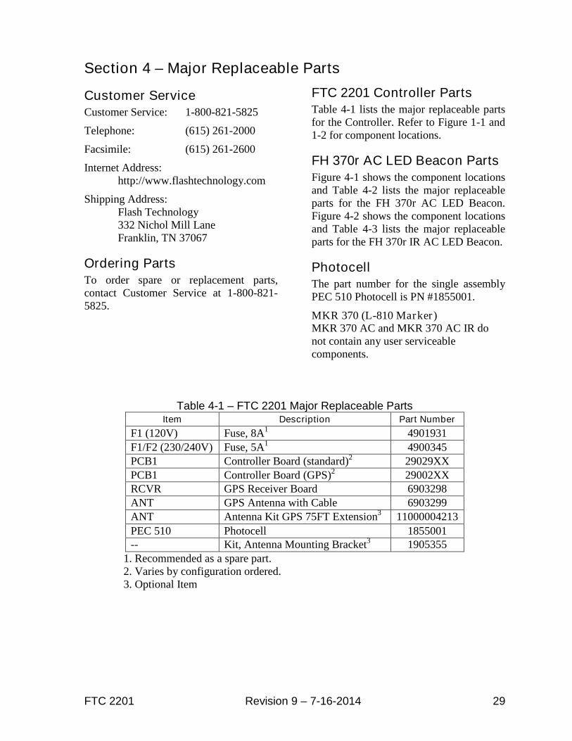
FTC 2201 Controller PartsTable 4-1 lists the major replaceable partsfor the Controller. Refer to Figure 1-1 and1-2 for component locations.
FH 370r AC LED Beacon PartsFigure 4-1 shows the component locationsand Table 4-2 lists the major replaceableparts for the FH 370r AC LED Beacon.Figure 4-2 shows the component locationsand Table 4-3 lists the major replaceableparts for the FH 370r IR AC LED Beacon.
PhotocellThe part number for the single assemblyPEC 510 Photocell is PN #1855001.
MKR 370 (L-810 Marker)MKR 370 AC and MKR 370 AC IR donot contain any user serviceablecomponents.
Table 4-1 – FTC 2201 Major Replaceable PartsItem Description Part Number
F1 (120V) Fuse, 8A1 4901931F1/F2 (230/240V) Fuse, 5A1 4900345PCB1 Controller Board (standard)2 29029XXPCB1 Controller Board (GPS)2 29002XXRCVR GPS Receiver Board 6903298ANT GPS Antenna with Cable 6903299ANT Antenna Kit GPS 75FT Extension3 11000004213
PEC 510 Photocell 1855001-- Kit, Antenna Mounting Bracket3 1905355
1. Recommended as a spare part.2. Varies by configuration ordered.3. Optional Item

30 Revision 9 – 7-16-2014 FTC 2201
Figure 4-1 – FH 370r AC Component Locations
Table 4-2 – FH 370r AC Replaceable Parts
Description Part Number
POWER SUPPLY FH 370r AC 2423000
SURGE SUPPRESSOR 220V 40kVA 11000010290
TERMINAL BLOCK ASSEMBLY 1362032
HINGE PIN AND LANYARD ASSEMBLY 1005303
FH 370r AC LIGHT ENGINE REPLACEMENT 1370165

FTC 2201 Revision 9 – 7-16-2014 31
Figure 4-2 – FH 370r IR AC Component Locations
Table 4-3 – FH 370r IR AC Replaceable Parts
Description Part Number
POWER SUPPLY FH 370r IR AC 2423200
SURGE SUPPRESSOR 220V 40kVA 11000010290
TERMINAL BLOCK ASSEMBLY 1362032
HINGE PIN AND LANYARD ASSEMBLY 1005303
FH 370r IR AC LIGHT ENGINE REPLACEMENT 1370040

RMA Policy Revision 2014A
Return Material Authorization (RMA) Policy
IF A PRODUCT PURCHASED FROM FLASH TECHNOLOGY MUST BE RETURNED FOR ANYREASON (SUBJECT TO THE WARRANTY POLICY), PLEASE FOLLOW THE PROCEDURE BELOW:
Note: An RMA number must be requested from Flash Technology prior to shipment of anyproduct. No returned product will be processed without an RMA number. This number will be theonly reference necessary for returning and obtaining information on the product’s progress.
1. To initiate an RMA: Call Flash Technology’s National Operations Center (NOC) at (800-821-
5825) to receive technical assistance and a Service Notification number. The following
information is required before a Service Notification number can be generated:
• Site Name/Number / FCC Registration number/ Call Letters or Airport Designator
• Site Owner (provide all that apply – owner, agent or subcontractor)
• Contractor Name
• Contractor Company
• Point of Contact Information: Name, Phone Number, Email Address, Fax Number and Cell Phone
(or alternate phone number)
• Product’s Serial Number
• Product’s Model Number or part number
• Service Notification Number (if previously given)
• Reason for call, with a full description of the reported issue
2. The Service Notification number will then serve as a precursor to receiving an RMA number if
it is determined that the product or equipment should be returned. To expedite the RMA
process please provide:
• Return shipping method• Shipping Address• Bill to Address• Any additional information to assist in resolving the issue or problem
3. Product within the Warranty Time Period
a. If to be returned for repair;
• RMA # is generated
• Once product is received and diagnosed;
• Covered under warranty – product is repaired or replaced
• Not covered under warranty – quote is sent to the customer for a bench fee of
$350 plus parts for repair
• If the customer does not want the product repaired, a $50 test fee is
charged before being returned
b. If advance replacement;
• Purchase order may be required before the advance replacement order is created
• RMA # is generated and the advance replacement order is created
• Once product is received and diagnosed;
• Covered under warranty – credit given back if PO received
• Not covered under warranty – credit will not be applied to PO
• Flash Technology has sole discretion in determining warranty claims. Flash Technology
reserves the right to invoice for parts advanced if the associated failed parts are not
returned within 15 days of issue or if product received is diagnosed to be non-warranty.

Revision 2014A RMA Policy
• Advance replacements will be shipped ground unless the customer provides alternative
shipping methods.
4. Product outside the Warranty Time Period
a. For Xenon System board repair; a purchase order is required at time of request for a RMA # for a
standard $350 repair bench fee
• RMA # is generated with the PO attached
• If the board is deemed non-repairable after diagnosis, the customer is notified. If the
customer purchases a new board, the repair bench fee is waived. If the customer does
not buy a new board, a $50 test fee is charged before being returned or scrapped.
b. For all other products; no purchase order is required to return the product for diagnosis
• RMA # is generated
• Once product is diagnosed, quote is sent to the customer for a bench fee of $350 plus
parts for repair
• Once the purchase order is received, the product will be repaired and returned
• If the customer does not want the product repaired, a $50 test fee is charged
before being returned or scrapped.
5. After receiving the Flash Technology RMA number, please adhere to the following packaging
guidelines:
• All returned products should be packaged in a way to prevent damage in transit. Adequate packingshould be provided taking into account the method of shipment.Note: Flash Technology will not be responsible for damaged items if product is not returned inappropriate packaging.
6. All packages should clearly display the RMA number on the outside of all RMA shipping
containers. RMA products (exact items and quantity) should be returned to:
Flash TechnologyAttn: RMA #XXX332 Nichol Mill LaneFranklin, TN 37067
7. All RMA numbers:
• Are valid for 30 days. Products received after 30 days may result in extra screening and delays.• Must have all required information provided before an RMA number is assigned.