ftj#-f!td .all models in stock na &. rabulll chelsea p · for hino model 338.....17 gmt p.t.o....
TRANSCRIPT

Bulletin HY25-1380-M1/US
Owner’s Manual Power Take-Offs Effective: February 2010
Supersedes: HY25-1380-M1/US December 2009
267 Series269 Series
277 Series278 Series
859 Series867 Series
Brought to you by Pro Gear & Transmission courtesy of Parker Hannifin Chelsea PTO
For parts or service contact us, Pro Gear & Transmission, Inc. [email protected]
ftJ#-f!tD Na• &. Rabulll CHELSEA P1TO
.All Models in stock
CHELSEA®
Parker

Parker Hannifin CorporationChelsea Products DivisionOlive Branch, MS 38654 USA
II
FAILURE OR IMPROPER SELECTION OR IMPROPER USE OF THE PRODUCTS DESCRIBED HEREIN OR RELATED ITEMS CAN CAUSE DEATH, PERSONAL INJURY AND PROPERTY DAMAGE.
This document and other information from Parker-Hannifin Corporation, its subsidiaries and authorized distributors provide product or system options for further investigation by users having technical expertise.
The user, through its own analysis and testing, is solely responsible for making the final selection of the system and components and assuring that all performance, endurance, maintenance, safety and warning requirements of the application are met. The user must analyze all aspects of the application, follow applicable industry standards, and follow the information concerning the product in the current product catalog and in any other materials provided from Parker or its subsidiaries or authorized distributors.
To the extent that Parker or its subsidiaries or authorized distributors provide component or system options based upon data or specifications provided by the user, the user is responsible for determining that such data and specifications are suitable and sufficient for all applications and reasonably foreseeable uses of the components or systems.
WARNING — User Responsibility
The items described in this document are hereby offered for sale by Parker Hannifin Corporation, its subsidiaries or its authorized distributors. This offer and its acceptance are governed by the provisions stated in the "Offer of Sale".
Offer of Sale
© Copyright 2010, Parker Hannifin Corporation, All Rights Reserved
The Chelsea® Power Take-Off or its components shipped with this owner’s manual may be manufactured under one or more of the following U.S. patents:4610175 5228355 4597301 5645363 6151975 6142274 6260682 7159701 B2 7,510,064Other patents pending.
Patent Information
Parker lchelsea

Bulletin HY25-1380-M1/US Owner’s Manual
Parker Hannifin CorporationChelsea Products DivisionOlive Branch, MS 38654 USA
III
General InformationSafety Information .........................................................................................................................1-2Pump Support Recommendations ................................................................................................3Foreword .......................................................................................................................................4Chelsea P.T.O. Safety Label Instructions .......................................................................................5-6Function of Auxiliary Power Shafts ................................................................................................7Spicer® Universal Joint Engineering Data .....................................................................................8
Allison Transmission Installation InstructionsMounting 267, 269, 277, 278, 859 and 867 P.T.O. on the Allison Transmission ....................................................................................................................9-11Pressure Port and Aperture Opening Identification ......................................................................12Hose Specifications by Transmission ............................................................................................12Shift Installation w/o Electronic Overspeed Control Old Style Valve ............................................................................................................................13Shift Installation w/o Electronic Overspeed Control New Style Valve...........................................................................................................................14Shift Installation w/ Electronic Overspeed Control New Style Valve ..............................................15Shift Installation with Remote Mount Solenoid ..............................................................................16Shift Installation 277 Series with Remote Solenoid for Hino Model 338 ......................................................................................................................17GMT P.T.O. Connector ...................................................................................................................18P.T.O./Combo Valve Installation Sketch 277/278 series
Old Style Valve ...........................................................................................................................19P.T.O./Combo Valve Installation Sketch 277/278 series
New Style Valve ..........................................................................................................................20Caterpillar Transmission Installation Instructions
Mounting 267, 269, 277, 278, 859 and 867 P.T.O. on the Caterpillar Transmission ..............................................................................................................21-23Shift Installation Sketch without Overspeed Control .....................................................................24Shift Installation Sketch with Overspeed Control ..........................................................................25Shift Installation Kit with Remote Mount Solenoid .........................................................................26Pressure Port Location and Hose Chart .......................................................................................27
Installation Instructions“RY” Wet Spline Installation Sketch ...............................................................................................28“AF” Wet Spline Installation Sketch (267) ......................................................................................28“AK” Wet Spline Installation Sketch ...............................................................................................29“AF” Wet Spline Installation Sketch (277/278)
Old Style Valve ..........................................................................................................................30“AF” Wet Spline Installation Sketch (277/278)
New Style Valve .........................................................................................................................31“XY” Wet Spline Installation Sketch ...............................................................................................32“ZY” Wet Spline Installation Sketch ..............................................................................................33Capscrew Installation ....................................................................................................................34Rotatable Flange Torque Specifications ........................................................................................34P.T.O. Shifting Procedure & Precautions .......................................................................................35P.T.O. Maintenance ........................................................................................................................38Offer of Sale ..................................................................................................................................39
Contents 10-Bolt Powershift P.T.O.s
Parker lchelsea

Bulletin HY25-1380-M1/US Owner’s Manual
Parker Hannifin CorporationChelsea Products DivisionOlive Branch, MS 38654 USA
IV
Parker lchelsea

Bulletin HY25-1380-M1/US Owner’s Manual
Parker Hannifin CorporationChelsea Products DivisionOlive Branch, MS 38654 USA
1
General Information 10-Bolt Powershift P.T.O.s
This symbol warns of possible personal injury.
These instructions are for your safety and the safety of the end user. Read them carefully until you understand them.
General Safety Information
To prevent injury to yourself and/or damage to the equipment:
■ Read carefully all owner’s manuals, service manuals, and/or other instructions.■ Always follow proper procedures, and use proper tools and safety equipment.■ Be sure to receive proper training.■ Never work alone while under a vehicle or while repairing or maintaining equipment.■ Always use proper components in applications for which they are approved.■ Be sure to assemble components properly.■ Never use wornout or damaged components.■ Always block any raised or moving device that may injure a person working on or under a vehicle.■ Never operate the controls of the Power Take-Off or other driven equipment from any position that could result in getting caught in the moving machinery.
Proper Matching of P.T.O.
WARNING: A Power Take-Off must be properly matched to the vehicle transmission and tothe auxiliary equipment being powered. An improperly matched Power Take-Off could cause severe damage to the vehicle transmission, the auxiliary driveshaft, and/or to the auxiliary equipment being powered. Damaged components or equipment could malfunction causing serious personal injury to the vehicle operator or to others nearby.
To avoid personal injury and/or equipment damage:
■ Always refer to Chelsea catalogs, literature, and owner’s manuals. Follow Chelsea recommendations when selecting, installing, repairing, or operating a Power Take-Off.■ Never attempt to use a Power Take-Off not specifically recommended by Chelsea for the vehicle transmission.■ Always match the Power Take-Off’s specified output capabilities to the requirements of the equipment to be powered.■ Never use a Power Take-Off whose range of speed could exceed the maximum.
Cold Weather Operation of Powershift P.T.O.
WARNING: During extreme cold weather operation [32°F (0°C) and lower], a disengaged Powershift Power Take-Off can momentarily transmit high torque that will cause unexpected output shaft rotation. This is caused by the high viscosity of the transmission oil when it is extremely cold. As slippage occurs between the Power Take-Off clutch plates, the oil will rapidly heat up and the viscous drag will quickly decrease.
The Power Take-Off output shaft rotation could cause unexpected movement of the driven equipment resulting in serious personal injury, death, or equipment damage.
To avoid personal injury or equipment damage:
■ Driven equipment must have separate controls.■ The driven equipment must be left in the disengaged position when not in operation.■ Do not operate the driven equipment until the vehicle is allowed to warm up.
Safety Information
A
A
A
Parker lchelsea

Bulletin HY25-1380-M1/US Owner’s Manual
Parker Hannifin CorporationChelsea Products DivisionOlive Branch, MS 38654 USA
2
General Information 10-Bolt Powershift P.T.O.s
Rotating Auxiliary Driveshafts
WARNING:■ Rotating auxiliary driveshafts are dangerous. You can snag clothes, skin, hair, hands, etc. This can cause serious injury or death.■ Do not go under the vehicle when the engine is running.■ Do not work on or near an exposed shaft when the engine is running.■ Shut off the engine before working on the Power Take-Off or driven equipment.■ Exposed rotating driveshafts must be guarded.
Guarding Auxiliary Driveshafts
WARNING: We strongly recommend that a Power Take-Off and a directly mounted pump be used to eliminate the auxiliary driveshaft whenever possible. If an auxiliary driveshaft is used and remains exposed after installation, it is the responsibility of the vehicle designer and P.T.O. installer to install a guard.
Using Set Screws
WARNING: Auxiliary driveshafts may be installed with either recessed or protruding set screws. If you choose a square head set screw, you should be aware that it will protrude above the hub of the yoke and may be a point where clothes, skin, hair, hands, etc. could be snagged. A socket head set screw, which may not protrude above the hub of the yoke, does not permit the same amount of torquing as does a square head set screw. Also, a square head set screw, if used with a lock wire, will prevent loosening of the screw caused by vibration. Regardless of the choice made with respect to a set screw, an exposed rotating auxiliary driveshaft must be guarded.
Important: Safety Information and Owner’s ManualChelsea Power Take-Offs are packaged with safety information decals, instructions, and an owner’s manual. These items are located in the envelope with the P.T.O. mounting gaskets. Also, safety infor-mation and installation instructions are packaged with some individual parts and kits. Be sure to read the owner’s manual before installing or operating the P.T.O. Always install the safety information decals according to the instructions provided. Place the owner’s manual in the vehicle glove compart-ment.
WARNING: Operating the P.T.O. with the Vehicle in Motion
Some Power Take-Offs may be operated when the vehicle is in motion. To do so, the P.T.O. must have been properly selected to operate at highway speeds and correctly matched to the vehicle transmission and the requirements of the driven equipment.
If in doubt about the P.T.O. specifications and capabilities, avoid operating the P.T.O. when the vehicle is in motion. Improper application and/or operation can cause serious personal injury or premature failure of the vehicle, the driven equipment, and/or the P.T.O.
Always remember to disengage the P.T.O. when the driven equipment is not in operation.
Pump Installation PrecautionsUse a bracket to support the pump to the transmission if:
■ The pump weighs 40 pounds [18.4 kg] or more.■ The combined length of the P.T.O. and pump is 18 inches [45.72 cm] or more from the P.T.O. centerline to the end of the pump.
This symbol warns of possible personal injury.
Safety Information (Continued)
A
A
A
A
A
Parker lchelsea

Bulletin HY25-1380-M1/US Owner’s Manual
Parker Hannifin CorporationChelsea Products DivisionOlive Branch, MS 38654 USA
3
General Information 10-Bolt Powershift P.T.O.s
Direct Mount Pump Support Recommendations
Chelsea strongly recommends the use of pump supports (Support Brackets) in all applications. P.T.O. warranty will be void if a pump bracket is not used when:1) The combined weight of pump, fittings and hose exceed 40 pounds [18.14 kg].2) The combined length of the P.T.O. and pump is 18 inches [45.72 cm] or more from the P.T.O. centerline to the end of the pump.
ALSO: Remember to pack the female pilot of the P.T.O. pump shaft with grease before installing the pump on the P.T.O. (reference Chelsea grease pack 379688)
Use caution to ensure that bracket does not pre-load pump/P.T.O. mounting
NOTe: For Proper Bracketing Attach at 2 or More Transmission Bolt Locations and 2 or More Pump Locations. Contact Transmission Manufacture for Proper Bracket Mounting Locations.
This symbol warns of possible personal injury.
"
A
A
Parker lchelsea
fo9 ~

Bulletin HY25-1380-M1/US Owner’s Manual
Parker Hannifin CorporationChelsea Products DivisionOlive Branch, MS 38654 USA
4
Since our major objective is to show you how to get additional and more profitable miles from truck, tractor and trailer components, we want to provide you with information on the installation of Chelsea Power Take-Offs.
We all realize that an inadequate transmission will overwork any Power Take-Off in a very short period of time. In addition, a mismatched transmission/P.T.O. combination can result in unsatisfactory perfor-mance of the equipment right from the start.
Before you order new trucks, be sure you’re getting the right transmission/P.T.O. combination. It is of vital importance for efficient performance to have adequate power. To help you select the proper type, size and design of P.T.O. it is advisable to discuss your specific requirements with Chelsea P.T.O. spe-cialists. They know their products and have easy access to manufacturers of equipment, transmissions and Power Take-Offs. They can inform you about everything you need to know about power, at the right time, before you specify components.
exploded View of a Typical Powershift P.T.O.
Foreword
General Information 10-Bolt Powershift P.T.O.s
Parker lchelsea

Bulletin HY25-1380-M1/US Owner’s Manual
Parker Hannifin CorporationChelsea Products DivisionOlive Branch, MS 38654 USA
5
Installation Instructions
Chelsea P.T.O. Safety Label Instructions
1. The two black and orange on white 5" x 7" pressure sensitive vinyl labels, part number 379274; must be placed on the vehicle frame rails (one (1) on each side), in a position that would be HIGHLY visible to anyone that would go under the truck near the P.T.O. rotating shaft. If the vehicle is to be painted after these labels are installed, cover them with two (2) blank masking covers. Remove the masking covers after painting.
2. Place the one (1) black and orange on white 3.5" x 5" pressure sensitive vinyl label, part number 379275, on the visor nearest the operator of the vehicle, this must be placed near the P.T.O. visor label.
3. Place the one (1) red and white with black lettering 3.5" x 7.5" pressure sensitive vinyl label, part number 379915, on the opposite side of the visor from the above label # 379275.
4. Place the one (1) white and black heavy duty card, part number 379276, in the vehicle glove box. Again in a position highly visible to the operator, for example: try to place this card on top of whatever may be in the glove box.
If you require labels, please order part number 328946X at no charge from your local Chelsea Warehouse or send request direct to:
Parker Hannifin CorporationChelsea Products Division8225 Hacks Cross RoadOlive Branch, MS 38654Customer Service: (662) 895-1011
10-Bolt Powershift P.T.O.s
Parker lchelsea

Bulletin HY25-1380-M1/US Owner’s Manual
Parker Hannifin CorporationChelsea Products DivisionOlive Branch, MS 38654 USA
6
Installation Instructions
7
10-Bolt Powershift P.T.O.s
Parker lchelsea

Bulletin HY25-1380-M1/US Owner’s Manual
Parker Hannifin CorporationChelsea Products DivisionOlive Branch, MS 38654 USA
7
Installation Instructions
Spicer® Universal Joint Operating Angles Prop. Max. Normal Prop. Max. Normal Shaft R.P.M. Operating Angle Shaft R.P.M. Operating Angle 3000 5° 50' 1500 11° 30' 2500 7° 00' 1000 11° 30' 2000 8° 40' 500 11° 30'Above based on angular acceleration of 100 RAD/SEC2
An auxiliary power shaft transmits torque from the power source to the driven accessory. The shaft must be capable of transmitting the maximum torque and R.P.M. required of the accessory, plus any shock loads that develop.
An auxiliary power shaft operates through constantly relative angles between the power source and the driven accessory, therefore, the length of the auxiliary power shaft must be capable of changing while transmitting torque. This length change, commonly called “slip movement”, is caused by movement of the power train due to torque reactions and chassis deflections.
Joint operating angles are very important in an auxiliary power joint application. In many cases, the longevity of a joint is dependent on the operating angles. (See chart below)
This information is limited to 1000 through 1310 series applications. For applications requiring a series larger than 1310, contact your local Chelsea distributor.
Determining Shaft Type1) Solid or tubular? a) In applications requiring more than 1000 R.P.M. or where the application necessitates a highly bal anced auxiliary power shaft, a tubular shaft should be used. b) Spicer’s solid shafting auxiliary power joints are designed for 1000 or less R.P.M. intermittent service such as: Driving small hydraulic pumps Driving winches Driving low speed product pumps2) Joint Series should be determined using the chart on the following page.
Function of Auxiliary Power Shafts
10-Bolt Powershift P.T.O.s
Parker lchelsea

Bulletin HY25-1380-M1/US Owner’s Manual
Parker Hannifin CorporationChelsea Products DivisionOlive Branch, MS 38654 USA
8
Installation Instructions 10-Bolt Powershift P.T.O.s
Spicer® Universal Joint engineering Data
Joint Series 1000 1100 1280 1310Torque Rating Automotive (Gas or Diesel Engine) Lbs. ft. Continuous 50 54 95 130
Tubing Diameter 1.750 1.250 2.500 3.00 Wall Thickness .065 .095 .083 .083 W = Welded S = Seamless W S W W
Flange Diameter (Swing Diameter) Rectangular Type 3.500 3.500 3.875 3.875
Bolt Holes - Flange Yoke Circle 2.750 2.750 3.125 3.125 Diameter .312 .312 .375 .375 Number 4 4 4 4 Male Pilot Dia. 2.250 2.250 2.375 2.375
Distance Across Lugs Snap Ring 2.188 2.656 3.469 3.469 Construction
Bearing Diameter .938 .938 1.062 1.062
Maximum Operating Speed * By Tube Size, Solid Shaft Size, and Length*(For speed below 500 R.P.M. or over 2500 R.P.M., contact your Chelsea Distributor)
Tubing Dia. & Max. Installed Length in Inches for Given R.P.M. Wall Thickness Centerline to Centerline of Joints for a Two Joint Assembly Joint & Shaft or (W=Welded Centerline of Joint to Centerline of Center Bearing for a Joint & Shaft S=Seamless) R.P.M. - Revolutions per Minute
500 1000 1500 2000 2500
1.750" X .065" W 117" 82" 67" 58" 52"
1.250" X .095" S 91" 64" 52" 45" 40"
2.500" X .083" W 122" 87" 70" 62" 55"
3.000" X .083" W - - - 85" 76" Solid Shaft Diameter
.750" 60" 42" 35" 30" 27"
.812" 62" 44" 36" 31" 28"
.875" 65" 46" 37" 32" 29"
1.000" 69" 49" 40" 35" 31"
1.250" 77" 55" 45" 39" 35"
Parker lchelsea

Bulletin HY25-1380-M1/US Owner’s Manual
Parker Hannifin CorporationChelsea Products DivisionOlive Branch, MS 38654 USA
9
Installation Instructions
Mounting the P.T.O. on the Transmission
Fig. 4
Fig. 3
Fig. 1
Fig. 2
3. Remove the gasket and clean the aperture surface (Fig. 3).
NOTe: Do not reuse the gasket that comes with the transmission.
4. Using a screwdriver, install the guide pins until they bottom out (Fig. 4) (Refer to Page 34 for correct location and use).
NOTe: Do not use sealing compounds because they are generally incompatible with automatic transmission fluid.
When installing a P.T.O., always wear protective clothing and safety glasses.
1. Begin by draining the oil from the transmis-sion. Use caution, since the oil may be hot (Fig. 1).
NOTe: Installation shown is for Right Side (Street Side) of Transmission.
2. Remove the P.T.O. aperture plate with a 15mm socket (Fig. 2).
Allison World Transmission P.T.O.s
Parker lchelsea

Bulletin HY25-1380-M1/US Owner’s Manual
Parker Hannifin CorporationChelsea Products DivisionOlive Branch, MS 38654 USA
10
Installation Instructions
Fig. 6
Fig. 7
Fig. 8
5. Install the special gasket over the guide pins. The ribbed surface should face outward, toward the installer (Fig. 5).
NOTe: To ensure proper backlash and sealing of P.T.O. to transmission only use gasket furnished with the P.T.O.
6. Position the P.T.O. and secure it with the top capscrew (Fig. 6).
NOTe: Refer to page 34 for proper capscrew installation for the 269 & 278 Series
7. Install the remaining capscrews. Torque all to 40 - 50 Lbs. ft. (54 - 68 N.m. or 5.5 - 6.9 Kg.m) (Fig. 7).
8. Install P.T.O. pressure switch, part # 379502, into port on Hydraulic Valve Cap. Torque to 120-140 In-lbs (Fig. 8).
Allison World Transmission P.T.O.s
Fig. 5
Mounting the P.T.O. on the Transmission (Continued)
Parker lchelsea

Bulletin HY25-1380-M1/US Owner’s Manual
Parker Hannifin CorporationChelsea Products DivisionOlive Branch, MS 38654 USA
11
Installation Instructions
Mounting the P.T.O. on the Transmission (Continued)
Fig. 10
▼
▼
▼
▼
Fig. 9
Fig. 11 (Right side shown)
Fig. 13Fig. 12
9. If using a rotatable flange see page 34 for bolt torque specifications. (Fig. 9).
10. Securely attach the high pressure line to the P.T.O. valve (Fig. 10).
11. Use the special fitting to securely attach the high pressure line to the transmission. This fitting is included with the P.T.O. (Fig. 11). See the chart on page 12 for the correct hose specifications. With the hose and P.T.O. securely connected, refill the transmission to the manufacturer’s suggested specifications.
12. Complete the assembly by installing the electrical connection to the valve assembly (Fig. 12) and the pressure switch (Fig 13).
Allison World Transmission P.T.O.s
Parker lchelsea

Bulletin HY25-1380-M1/US Owner’s Manual
Parker Hannifin CorporationChelsea Products DivisionOlive Branch, MS 38654 USA
12
Installation Instructions
Pressure Port and Aperture Opening Identification
1. These drawings represent left and right views of the MD and HD pressure ports on the transmission.
Allison World Transmission P.T.O.s
An HD with 2 P.T.O.’s requires a 379556 “T” fitting and a 379703 swivel nut 90 degree elbow to attach 2 hoses to the single port on the left side.
1 Lubrication Option “R”, shifter Options “G” and “H” for 277 and 859 Series
2 Lubrication Option “R” for 278 Series
Standard Hose Specifications by Transmission
TRANS. LOCATION 267 Series 277 Series 278 Series 859 Series MD Top Right (Right Press. Port) 329130-6X 329075-2X 329075-2X 329075-2X MD L.H. Side (Left Press. Port) 329130-1X 329130-5X 329130-5X 329130-5X MD R.H. Side (Right Press. Port) 329130-4X 329075-1X 329075-1X 329075-1X HD Top Right (Left Press. Port) 329130-6X 329075-2X 329075-2X 329075-2X HD L.H. Side (Left Press. Port) 329130-1X 329130-4X 329075-4X 329130-4X HD1, 2 L.H. Side (Left Press. Port) — 329130-5X 329130-5X 329130-5X HD1, 2 Top Right (Right Press. Port) — 329130-4X 329075-4X 329130-4X MD1, 2 L.H. Side (Left Press. Port) — 329130-5X 329130-5X 329130-5X MD1, 2 R.H. Side (Right Press. Port) — 329075-1X 329075-1X 329075-1X
Allison10-Bolt Pad97-Teeth
Main Pressure Port.438-20UNF-2ALeft Side Only
13.61[345.7]
68-Teeth
83-Teeth
Main Pressure Port.438-20UNF-2A175 to 255 P.S.I.Both Sides
Main Pressure Port.438-20UNF-2A175 to 255 P.S.I.Both Sides
10.15[257.8]
24.33[618.0]
Allison10-Bolt Pad
Main Pressure Port.438-20UNF-2A175 to 255 P.S.I.Both Sides
10.15[257.8]
24.33[618.0]
Allison10-Bolt Pad
Main Pressure Port.438-20UNF-2A175 to 255 P.S.I.Both Sides
Top/Left
Top/Left
Right/Left
MD
HD
MDy
..
y
..
Parker lchelsea

Bulletin HY25-1380-M1/US Owner’s Manual
Parker Hannifin CorporationChelsea Products DivisionOlive Branch, MS 38654 USA
13
Shift Installation Kit 277, 278 & 859 Series without electronic Overspeed Control (SK-347 Rev C) (Old Style)
Installation Sketch Allison World Transmission P.T.O.s
3792
65 G
rom
met
Bla
ck W
ire
3795
04 V
alve
Con
nect
ion
and
Wire
Ass
embl
y
Red
Wire
3795
02 P
ress
ure
Sw
itch
See
Hos
e C
hart
pa
ge 1
237
9486
90°
Fitt
ing
Inst
all i
n Tr
ansm
issi
on
Hig
h P
ress
ure
Por
tM
D: L
eft o
r R
ight
Sid
eH
D: L
eft S
ide
Onl
y3792
57 S
plic
e C
onne
ctor
3799
00 F
use
Hol
der
10 A
mp
Fus
e
Whi
te
Red
Wire
3793
36 B
rack
et
Indi
cato
r Li
ght
Blu
e W
ire
Pos
itive
Ter
min
al o
f Ig
nitio
n or
Bat
tery
Dril
l 1"
Dia
. Hol
e in
Fire
wal
l
Red
Wire
Run
Wire
s T
hrou
gh
Gro
mm
et in
Fire
wal
l
Ele
ctric
al G
roun
d of
Cab
or
Fram
e
Acc
epts
#1
0 S
crew
3793
06
Spa
de
Term
inal
3792
52
But
t Con
nect
or
3788
81S
witc
h37
9005
24
Vol
t37
9978
12
Vol
t
3290
24-1
2X 1
2V In
stal
latio
n K
it32
9024
-24X
24V
Inst
alla
tion
Kit
"R"
Lu
bri
cati
on
O
pti
on
278
Ser
ies
I
0
Parker lchelsea

Bulletin HY25-1380-M1/US Owner’s Manual
Parker Hannifin CorporationChelsea Products DivisionOlive Branch, MS 38654 USA
14
Shift Installation Kit 277, 278 & 859 Series without electronic Overspeed Control (SK-347 Rev e) (New Style)
Installation Sketch Allison World Transmission P.T.O.s
P.T.O
. IS E
NG
AGED
WH
EN L
IGH
T IS
ON
NWD
NWD
PAT.
PAT.
REA
DO
WN
ERS
MA
NU
AL
O N
O F F
3792
65 G
rom
met
Bla
ck W
ire
3795
04 V
alve
Con
nect
ion
and
Wire
Ass
embl
y
Red
Wire
3795
02 P
ress
ure
Sw
itch
See
Hos
e C
hart
pag
e 12
3794
86 9
0° F
ittin
gIn
stal
l in
Tran
smis
sion
H
igh
Pre
ssur
e P
ort
MD
: Lef
t or
Rig
ht S
ide
HD
: Lef
t Sid
e O
nly37
9257
Spl
ice
Con
nect
or
3799
00 F
use
H
olde
r 10
Am
p F
use
Whi
te
Red
Wire
3793
36 B
rack
et
Indi
cato
r Li
ght
Blu
e W
ire
Pos
itive
Ter
min
al o
f Ig
nitio
n or
Bat
tery
Dril
l 1"
Dia
. Hol
e in
Fire
wal
l
Red
Wire
Run
Wire
s T
hrou
gh
Gro
mm
et in
Fire
wal
l
Ele
ctric
al G
roun
d of
Cab
or
Fram
e
Acc
epts
#1
0 S
crew
3793
06S
pade
Ter
min
al
3792
52
But
t Con
nect
or
3788
81S
witc
h37
9005
24
Vol
t37
9978
12
Vol
t
3290
24-1
2X 1
2V In
stal
latio
n K
it32
9024
-24X
24V
Inst
alla
tion
Kit
"R"
Lu
bri
cati
on
O
pti
on
278
Ser
ies
3792
54-1
7 14
Gau
ge W
ire
w/F
ork
Term
inal
NO
Te
: * P
re -
200
5-C
onne
ct to
J1-
6 (T
CM
) or
Wire
#10
6
200
5 an
d La
ter
- C
onne
ct to
43
(TC
M)
or W
ire #
143.
*
Parker lchelsea

Bulletin HY25-1380-M1/US Owner’s Manual
Parker Hannifin CorporationChelsea Products DivisionOlive Branch, MS 38654 USA
15
Shift Installation Kit 277, 278 & 859 Series with electronic Overspeed Control (SK-472)
Installation Sketch Allison World Transmission P.T.O.s
NO
Te
S:
1) S
trip
Wire
End
s .2
5" P
rior
to In
stal
ling
in B
utt C
onne
ctor
(A
s N
eces
sary
)2)
Ref
eren
ce K
it 32
9076
X
NWD
PAT.
NWD
PAT.
Ele
ctric
al G
roun
dof
Cab
or
Fram
e
Acc
epts
.25"
Scr
ew
16 A
WG
Wire
, Bla
ckC
onne
ct T
o G
roun
d
16 A
WG
Wire
, Red
Con
nect
to 1
2 V
DC
or
24 V
DC
, 5A
Min
imum
Igni
tion
Circ
uit
2 W
ireS
hiel
ded
Cab
le
(1.0
")
(1.8
")
Ele
ctro
nic
Ove
rspe
edC
ontr
olle
r -
3296
50X
(4.9
")
Spe
ed S
enso
r E
xten
sion
Cab
le32
8923
-10X
(10
Ft.
Sup
plie
d w
/E.O
.C.)
3289
23-5
X (
5 F
t. O
ptio
nal C
able
)
Run
Cab
le th
roug
hG
rom
met
in F
irew
all
16 A
WG
Wire
, Blu
ew
ith B
utt C
onne
ctor
16 A
WG
Wire
, Gre
enw
ith B
utt C
onne
ctor
Slic
e G
rom
met
.in
sert
in H
ole
in F
irew
all
3792
65G
rom
met
Dril
l 1"
Hol
ein
Fire
wal
l
“Blu
e” W
ire
“Red
” Wire
Sad
dle
Spl
ice
Con
nect
orS
uppl
ied
by In
stal
ler
Wire
“A
”16
AW
G W
ire a
nd C
onne
ctor
Sup
plie
d by
Inst
alle
r
3792
43S
peed
Sen
sor
28-P
-171
O-R
ing
Rea
r C
over
Sho
wn
in“P
” Opt
ion
Pos
ition
Hos
e pe
r C
hart
(Ord
er S
epar
atel
y)
277/
278/
859
Ser
ies
Run
Wire
s th
roug
hG
rom
met
in F
irew
all
3795
04V
alve
Con
nect
oran
d W
ire A
ssem
bly
“Bla
ck” W
ireAcc
epts
#10
Scr
ewE
lect
rical
Gro
und
of C
ab o
r Fr
ame
3795
02P
ress
ure
Sw
itch
Rea
r C
over
Sho
wn
inS
tand
ard
“P” O
ptio
n P
ositi
on
3794
8690
° F
ittin
g In
stal
l in
Tran
smis
sion
Hig
h P
ress
ure
Por
tM
D: L
eft o
r R
ight
Sid
eH
D: L
eft S
ide
Onl
y
Hos
e P
er C
hart
(Ord
er S
epar
atel
y)
/ /
/ /
~
Parker lchelsea
/ C ___________ _

Bulletin HY25-1380-M1/US Owner’s Manual
Parker Hannifin CorporationChelsea Products DivisionOlive Branch, MS 38654 USA
16
Installation Sketch
Shift Installation Kit 277, 278, & 859 Series with Remote Mount Solenoid (SK-432 Rev C)
Allison World Transmission P.T.O.s
CHELSEA
N
R
INDICATOR
LIGHT DOES NOT
GUARANTEE
P.T.O. OPERATION.
IF LIGHT FAILS
CHECK BULB.
O
P.T.O. IS ENGAGED WHEN LIGHT IS ON
O F F
CCHELSEA
VALVEEXHAUST
PAT.
NWD
IN
CYL
Blu
e W
ire
Acc
epts
#10
Scr
ew
Bla
ck W
ire
Ele
ctric
al G
roun
d of
Cab
or
Fra
me
3792
65 G
rom
met
3292
31X
Val
ve C
onne
ctor
an
d W
ire A
ssem
bly
3292
30X
G
reen
Wire
3792
52
But
t Con
nect
or
3789
78
12 V
Indi
cato
r L
ight
3790
05
24 V
Indi
cato
r Li
ght
3793
36 B
rack
et
3792
57 S
plic
e C
onne
ctor
Pos
itive
Ter
min
al o
f Ign
ition
or
Bat
tery
3799
00
Fus
e H
olde
r
Ass
’y w
/10
Am
p F
use
3793
06 S
pade
Ter
min
al
3290
57-4
X H
ose
Ass
embl
y
3280
75X
Hos
e A
ssem
bly
3792
52
But
t Con
nect
or
3796
86-1
12
V S
olen
oid
Val
ve
3796
86-2
24
V S
olen
oid
Val
ve 3791
31-1
Ada
pter
3794
49 A
dapt
er
2x 5
0045
7-6
Mou
ntin
g S
crew
Hos
e P
er C
hart
(See
Cha
rt o
n P
age
12)
2x 5
0035
7-7
Lock
was
her
3794
86 9
0° F
ittin
g In
stal
l in
Tran
smis
sion
Hig
h P
ress
ure
Por
tM
D-L
eft o
r R
ight
Sid
eH
D-R
ight
Sid
e O
nly
NO
Te
: Thi
s op
tion
is n
ot a
vaila
ble
with
nor
can
it b
e us
ed o
n E
.O.C
. app
licat
ions
.
3788
81
Sw
itch
3292
37-1
2X 1
2V In
stal
latio
n K
it32
9237
-24X
24V
Inst
alla
tion
Kit
3797
11 T
ee F
ittin
g
3800
10
Sw
ivel
Uni
on
3794
8690
° F
ittin
g
3792
58
Mou
ntin
g B
rack
et
3797
00
Run
Tee
3290
57-4
XH
ose
Ass
’y
Dril
l 1"
Dia
. Hol
e in
Fire
wal
l
Slic
e G
rom
met
Inse
rt in
Hol
e
in F
irew
all
Run
Wire
s T
hrou
gh
Gro
mm
et in
Fire
wal
l
Torq
ue to
120
-156
In. L
bs.
Torq
ue to
16-
20 L
bs. f
t.
Oil
from
Tr
ans O
il to
P.T
.O. L
ube
Oil
to P
.T.O
. Clu
tch
3795
02
Pre
ssur
e S
witc
h
21-P
-701
3792
54-1
7 14
Gau
ge W
ire
w/F
ork
Term
inal
NO
Te
: * P
re -
200
5-C
onne
ct to
J1-
6 (T
CM
) or
Wire
#10
6
200
5 an
d La
ter
- C
onne
ct to
43
(TC
M)
or W
ire #
143.
*
I I
'*
r ··
l Parker lchelsea

Bulletin HY25-1380-M1/US Owner’s Manual
Parker Hannifin CorporationChelsea Products DivisionOlive Branch, MS 38654 USA
17
Shift Installation Kit 277 Series with Remote Mount Solenoid for Hino Model 338 (SK-410 Rev C)
Installation Sketch Allison World Transmission P.T.O.s
3292
37-1
2X 1
2V In
stal
latio
n K
it32
9237
-24X
24V
Inst
alla
tion
Kit
3294
41X
Pre
ssur
e S
witc
h R
eloc
atio
n K
it (H
ino)
CHELSEA
N
R
INDICATOR
LIGHT DOES NOT
GUARANTEE
P.T.O. OPERATION.
IF LIGHT FAILS
CHECK BULB.
O
P.T.O. IS ENGAGED WHEN LIGHT IS ON
O F F
IN
CYL
BUILT BYTES-2
MODEL NO.DATE:S/N
NWD
PAT.
3792
65
Gro
mm
et
Dril
l 1"
Dia
. Hol
e in
Fire
wal
l
Run
Wire
s T
hrou
gh
Gro
mm
et in
Fire
wal
l37
9252
B
utt
Con
nect
or
3788
81
Sw
itch
3793
06
Spa
de
Term
inal
3793
36
Bra
cket
Pos
itive
Ter
min
al o
f Ig
nitio
n or
Bat
tery
3792
57 S
plic
e C
onne
ctor
3799
00 F
use
Hol
der
Ass
embl
y w
/10
AM
P F
use
See
Hos
e C
hart
Pag
e 12
3291
30-1
X
Hos
e A
ssem
bly
3794
86
90°
Fitt
ing
3795
02 P
ress
ure
Sw
itch
3797
11
Tee
Fitt
ing
3291
30-1
0X
Hos
e A
ssem
bly
5003
57-7
Lo
ck W
ashe
r3291
30-1
X
Hos
e A
ssem
bly
3280
75X
H
ose
Ass
embl
y
3794
49
Ada
pter
3794
49
Ada
pter
3796
86-1
12v
S
olen
oid
Val
ve37
9686
-2 2
4v
Sol
enoi
d V
alve
5004
57-6
Scr
ews
3792
52 B
utt
Con
nect
or
Ele
ctric
al G
roun
d of
Cab
or
Fram
e
Acc
epts
#10
S
crew
Bla
ck W
ire
3794
86 9
0° F
ittin
g In
stal
l in
Tra
nsm
issi
on H
igh
Pre
ssur
e P
ort
3794
57 O
-Rin
g H
ex s
ocke
t pl
ug
3792
54-1
7 14
Gau
ge W
ire
w/F
ork
Term
inal
NO
Te
: * P
re -
2005
-Con
nect
to J
1-6
(TC
M)
o
r Wire
#10
6
200
5 an
d La
ter
- C
onne
ct to
43
(T
CM
) or
Wire
#14
3.
*
I
~
I I I
-- --- -- - .. ---=r .. _J
Parker lchelsea

Bulletin HY25-1380-M1/US Owner’s Manual
Parker Hannifin CorporationChelsea Products DivisionOlive Branch, MS 38654 USA
18
GMT P.T.O. ConnectorOwner’s ManualAllison World Transmission P.T.O.s
GMT C Series Trucks
For model year 2003 GM C Series 4500, 5500, 6500, 7500 and 8500 trucks may be equipped with the Allison World (MD) transmission. In these vehicles GM Truck has integrated a P.T.O. connector, located in the right hand engine compartment area. A Power Take-Off switch has also been incorporated into the GM dash panel to control P.T.O. operation. With the P.T.O. option ordered on the truck, the P.T.O. connector and in-dash switch simplify the interface for the body builder.
In order for the customer to utilize the full capability of the P.T.O./transmission, Chelsea has design a wiring harness that must be used between the GM P.T.O. connector and the Chelsea Power Take-Off. These are for P.T.O. Non E.O.C. applications only.
On the Allison World (MD) transmission the P.T.O. drive gear is engine driven. The wiring harness is not “required” for the Power Take-Offs listed on the chart, but must be used if the GM supplied in-dash P.T.O. switch is to be utilized.
See wiring harness part number 379926 for the 277, 278 and 859 Series Power Take-Offs.
2003 GM “C” Series Wiring Harness for 277, 278 and 859 SeriesPart Number 379926
10' 6"
To GM P.T.O. Connector
Black Wire Loom
Connect to Solenoid Valve
Connect to Pressure Switch
Parker lchelsea

Bulletin HY25-1380-M1/US Owner’s Manual
Parker Hannifin CorporationChelsea Products DivisionOlive Branch, MS 38654 USA
19
Installation Sketch Allison World Transmissions
P.T.O. Combo Valve Installation Sketch, 277/278 Series (SK-427 Rev B) (Old Style)
Caution: When installing nylon tubing avoid sharp angles, exhaust and manifold systems.
379252Butt Connector
Drill 1" Dia. Hole in Firewall379265 Grommet
Slice Grommet Insert in Hole in Firewall
Red Wire
379504 Valve Connector and Wire Assembly
Black Wire Accepts #10 Screw
Electrical Ground of Cab or Frame
Run Wires Through Grommet in Firewall
379306Spade Terminal
Blue Wire
379502 Pressure Switch
379547X Pressure Switch
380009 Female Connector
To P.T.O. Port Air Control Valve
379900 Fuse Holder Ass’y w/10 Amp Fuse
379257 Splice Connector
Positive Terminal of Ignition or Battery
379664 Red L.E.D. 12 Volt Indicator Light Assembly
37948690° FittingInstall in TransmissionHigh Pressure PortMD: Left or Right SideHD: Left Side Only
Hose Per Chart (See Chart on Page 12)
Hose Per Chart(See Chart on Page 12)
“R” Lubrication Option
Allison P.T.O. Shown
379042Male Connector
Warning: Connect directly to air supply. Do not use tubing between air supply and pressure protection valve.
378416Hex Nipple
378414Pressure Protection ValveOpens at 40 PSI
379044-71/4" Nylon TubingAir Supply
To Dump Pump Shifter “Lower Port”
379042Male Connector 379547
Pressure Switch
380009 Female Connector
379044-7 Nylon Tubing
379664 Red L.E.D. 12 volt Indicator Light Assembly
Cab
379042Male Connector
To Dump Pump Shifter “Raise Port”
Installation Kits328388-85X “S” Shifter328388-86X “T” Shifter
A
Parker lchelsea
I " __ __,,,
--- ---- -0 0 0
7 ! i
;--__ ,.,/
!
\ --- / 1~~"1..,..,., ..... "~
0-.--------~0
i. -l-0 G) 0-i-~-t'>========== -~ 'ff'. i 1:: I
i ~

Bulletin HY25-1380-M1/US Owner’s Manual
Parker Hannifin CorporationChelsea Products DivisionOlive Branch, MS 38654 USA
20
P.T.O. Combo Valve Installation Sketch, 277/278 Series (SK-427 Rev C) (New Style)
Installation Sketch Allison World Transmissions
Caution: When installing nylon tubing avoid sharp angles, exhaust and manifold systems.
379252Butt Connector
Drill 1" Dia. Hole in Firewall379265 Grommet
Slice Grommet Insert in Hole in Firewall
Red Wire
379504 Valve Connector and Wire Assembly
Black Wire Accepts #10 Screw
Electrical Ground of Cab or Frame
Run Wires Through Grommet in Firewall
379306Spade Terminal
Blue Wire
379502 Pressure Switch
379547X Pressure Switch
380009 Female Connector
To P.T.O. Port Air Control Valve379900 Fuse Holder
Ass’y w/10 Amp Fuse
379257 SpliceConnector
Positive Terminal of Ignition or Battery
379664 RedL.E.D. 12 VoltIndicator Light Assembly
37948690° FittingInstall in TransmissionHigh Pressure PortMD: Left or Right SideHD: Left Side Only
Hose Per Chart (See Chart on Page 12)
Hose Per Chart(See Chart on Page 12)
“R” Lubrication Option
Allison P.T.O. Shown
379042Male Connector
Warning: Connect directly to air supply. Do not use tubing between air supply and pressure protection valve.
378416Hex Nipple
378414Pressure Protection ValveOpens at 40 PSI
379044-71/4" Nylon Tubing
Air Supply
To Dump Pump Shifter “Lower Port”
379042Male Connector
379547 Pressure Switch
380009 Female Connector
379044-7 Nylon Tubing
379664 Red L.E.D. 12 volt Indicator Light Assembly
Cab
379042Male Connector
To Dump Pump Shifter “Raise Port”
Installation Kits328388-85X “S” Shifter328388-86X “T” Shifter
A
Parker lchelsea
\.._I
--=
7 I
I I
I I
( I
,-~===-" ,--+--
1<1l

Bulletin HY25-1380-M1/US Owner’s Manual
Parker Hannifin CorporationChelsea Products DivisionOlive Branch, MS 38654 USA
21
Installation Instructions
Mounting the P.T.O. on the Transmission
2. Remove the gasket and clean the aperture surface (Fig. 2).
NOTe: Do not reuse the gasket that comes with the transmission.
3. Using a screwdriver, install the guide pins until they bottom out (Fig. 3) (see page 34 ).
NOTe: Do not use sealing compounds because they are generally incompatible with automatic transmission fluid.
4. Install the special gasket over the guide pins. The ribbed surface should face outward, toward the installer (Fig. 4).
NOTe: To ensure proper backlash and sealing of the P.T.O. to the transmission, only use Gasket furnished with the P.T.O.
When installing a P.T.O., always wear protective clothing and safety glasses.
1. Remove the P.T.O. aperture plate with a 16mm socket (Fig. 1).
Caterpillar
Fig. 4
Fig. 1
Fig. 2
Fig. 3
Parker lchelsea

Bulletin HY25-1380-M1/US Owner’s Manual
Parker Hannifin CorporationChelsea Products DivisionOlive Branch, MS 38654 USA
22
Installation Instructions
5. Position the P.T.O. and secure it with the top capscrew provided. (Fig. 5)
NOTe: Refer to page 34 for proper capscrew installation for the 269 & 278 Series
6. Install the remaining capscrews. Torque them to 37-44 Lbs. ft. [50-60 N.m.] (Fig. 6).
NOTe: There are two (2) high pressure ports available. Use the port located on the driver’s side of the transmission unless there is an interference issue with a pump or driven object (Fig. 7).
7. Using the special fitting (379812) to securely attach the high pressure line to the transmission. This fitting is included with the P.T.O. Tighten to 8-10 Lbs. ft. [11.0 - 13.5 N.m.] (Fig. 8).
See the hose chart on page 27 for the correct hose specifications. Tighten hose end fitting 2 flats from finger tight
Caterpillar
Fig. 8
Fig. 5
Fig. 6
Fig. 7
Mounting the P.T.O. on the Transmission (Continued)
Parker lchelsea

Bulletin HY25-1380-M1/US Owner’s Manual
Parker Hannifin CorporationChelsea Products DivisionOlive Branch, MS 38654 USA
23
Installation Instructions
Mounting the P.T.O. on the Transmission (Continued)
9. Complete the assembly by installing the electrical connection (Fig. 10).
NOTe: See page 24-26 for electrical connection drawings.
NOTe: If using a rotatable flange, see page 34 for bolt torque.
Owner’s ManualCaterpillar
8. Securely attach the high pressure line to the valve. Tighten hose end fitting 2 flats from finger tight (Fig. 9).
Fig. 9
Fig. 10
Parker lchelsea

Bulletin HY25-1380-M1/US Owner’s Manual
Parker Hannifin CorporationChelsea Products DivisionOlive Branch, MS 38654 USA
24
Installation InstructionsOwner’s ManualCaterpillar
Shift Installation Kit 277, 278 and 859 Series without electronic Overspeed Control (SK-411 Rev A)
3790
03 2
4 V
olt I
ndic
ator
Li
ght
3789
78 1
2 V
olt I
ndic
ator
Li
ght
Dril
l 1"
Dia
. Hol
e In
Fire
wal
l37
9265
G
rom
met
Slic
e G
rom
met
, In
sert
in H
ole
in F
irew
all
3798
12 S
trai
ght F
ittin
gIn
stal
l in
Tran
smis
sion
Hig
h P
ress
ure
Por
t
Thi
s H
ose
Pur
chas
ed S
epar
atel
yS
ee H
ose
Cha
rt S
K-4
14 p
age
27
3793
36 B
rack
et
3793
06
Spa
de
Term
inal
3788
81
Sw
itch
3792
52 B
utt C
onne
ctor
Blu
e W
ireRun
Wire
s T
hrou
gh G
rom
met
in
Fire
wal
l
3799
28V
alve
Con
nect
or a
nd
Wire
Ass
embl
yR
ed W
ire
Bla
ck W
ire
3795
02 P
ress
ure
Sw
itch
Torq
ue V
alue
s m
ust b
e be
twee
n 12
0-14
4 lb
s. in
.
Torq
ue to
16
-20
Lbs.
ft.
3799
00 F
use
Hol
der
w/ 1
0 am
p F
use
3792
57 S
plic
e C
onne
ctor
Pos
itive
Ter
min
al o
f Ig
nitio
n or
Bat
tery
Ele
ctric
al
Gro
und
of C
ab
or F
ram
e
3294
43-1
2X -
For
12V
Inst
alla
tion
Kit
3294
43-2
4X -
For
24V
Inst
alla
tion
Kit
\ '\ I . _ _,.1
I
0
I
l
Parker lchelsea
.0 ~· t -•
.... ___ _ -- ----,
I I
0
Bulletin HY25-1380-M1/US Owner’s Manual
Parker Hannifin CorporationChelsea Products DivisionOlive Branch, MS 38654 USA
25
Installation Instructions
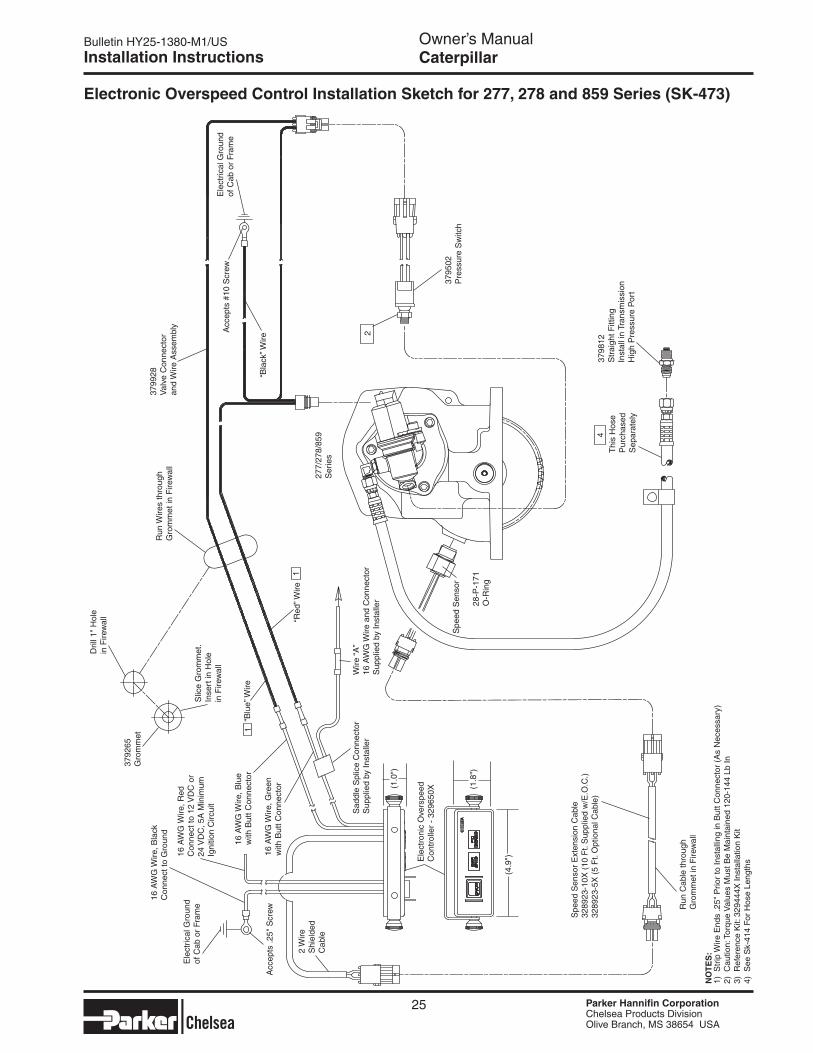
electronic Overspeed Control Installation Sketch for 277, 278 and 859 Series (SK-473)
Caterpillar
1) S
trip
Wire
End
s .2
5" P
rior
to In
stal
ling
in B
utt C
onne
ctor
(A
s N
eces
sary
)2)
Cau
tion:
Tor
que
Val
ues
Mus
t Be
Mai
ntai
ned
120-
144
Lb In
3) R
efer
ence
Kit:
329
444X
Inst
alla
tion
Kit
4) S
ee S
k-41
4 F
or H
ose
Leng
ths
NO
Te
S:
Ele
ctric
al G
roun
dof
Cab
or
Fram
e
Acc
epts
.25"
Scr
ew
16 A
WG
Wire
, Bla
ckC
onne
ct to
Gro
und
16 A
WG
Wire
, Red
Con
nect
to 1
2 V
DC
or
24 V
DC
, 5A
Min
imum
Igni
tion
Circ
uit
2 W
ireS
hiel
ded
Cab
le
Ele
ctro
nic
Ove
rspe
edC
ontr
olle
r -
3296
50X(1
.0")
(1.8
")
(4.9
")
Spe
ed S
enso
r E
xten
sion
Cab
le32
8923
-10X
(10
Ft.
Sup
plie
d w
/E.O
.C.)
3289
23-5
X (
5 F
t. O
ptio
nal C
able
)
Run
Cab
le th
roug
hG
rom
met
in F
irew
all
Sad
dle
Spl
ice
Con
nect
or
Sup
plie
d by
Inst
alle
r
16 A
WG
Wire
, Blu
ew
ith B
utt C
onne
ctor
16 A
WG
Wire
, Gre
enw
ith B
utt C
onne
ctor
3792
65G
rom
met
Slic
e G
rom
met
.In
sert
in H
ole
in F
irew
all
Dril
l 1"
Hol
ein
Fire
wal
l
“Blu
e” W
ire
“Red
” Wire
Wire
“A
”16
AW
G W
ire a
nd C
onne
ctor
Sup
plie
d by
Inst
alle
r
Spe
ed S
enso
r
28-P
-171
O-R
ing
Thi
s H
ose
Pur
chas
edS
epar
atel
y
3798
12S
trai
ght F
ittin
gIn
stal
l in
Tran
smis
sion
Hig
h P
ress
ure
Por
t
277/
278/
859
Ser
ies
Run
Wire
s th
roug
hG
rom
met
in F
irew
all
3799
28V
alve
Con
nect
oran
d W
ire A
ssem
bly
“Bla
ck” W
ire
Acc
epts
#10
Scr
ewE
lect
rical
Gro
und
of C
ab o
r Fr
ame
3795
02P
ress
ure
Sw
itch
4
2
1
1
--, I
I I
I
\ I
~ X l __
i 1 I
I I
J I I
I •
'\ I
Parker lchelsea

Bulletin HY25-1380-M1/US Owner’s Manual
Parker Hannifin CorporationChelsea Products DivisionOlive Branch, MS 38654 USA
26
Installation Instructions Caterpillar
Remote Mount Installation Sketch for 277, 278 and 859 (SK-413 Rev C)
Ele
ctric
al G
roun
d of
Cab
or
Fra
me
Acc
epts
#10
Scr
ewB
lack
Wire
3792
65G
rom
met S
lice
Gro
mm
etIn
sert
in H
ole
in F
irew
allDril
l 1"
Dia
. Hol
ein
Fire
wal
l
Run
Wire
s T
hrou
gh G
rom
met
in
Fire
wal
l
Blu
e W
ire
3799
28V
alve
Con
nect
oran
d W
ire A
ssem
bly
Red
Wire
3792
52B
utt C
onne
ctor
3789
78 -
12
Vol
t In
dica
tor
Ligh
t
3790
05 -
24
Vol
t In
dica
tor
Ligh
t
3788
81S
witc
h
3793
06S
pade
Ter
min
al
3799
00 F
use
Hol
der
Ass
embl
yw
/10
AM
P F
use
3792
57 S
plic
e C
onne
ctor
3793
36B
rack
et
Pos
itive
Ter
min
al o
f Ign
ition
or
Bat
tery
3794
86
90°
Elb
ow
3290
57-3
X H
ose
Ass
embl
yP
urch
ase
Sep
arat
ely
3798
12 S
trai
ght F
ittin
g In
stal
l in
Tran
smis
sion
Hig
h P
ress
ure
Por
t
3798
12 C
onne
ctor
3798
12
Con
nect
or
Val
ve E
xhau
st
3291
30-5
X O
il to
P.T
.O.
Clu
tch
Hos
e A
ss’y
Pur
chas
ed S
epar
atel
y
Pur
chas
ed S
epar
atel
y S
ee H
ose
Cha
rt
SK
-414
pag
e 27
Rem
ote
Val
ve A
ssem
bly
3294
46-1
2X -
12
Vol
t32
9446
-24X
- 2
4 V
olt
3798
12
Con
nect
orO
il fr
om
Tran
s
3294
45-1
2X 1
2V In
stal
latio
n K
it32
9445
-24X
24V
Inst
alla
tion
Kit
3795
02P
ress
ure
Sw
itch
3797
11 T
ee F
ittin
g
3800
10 U
nion
Sw
ivel
Nut
3797
00S
wiv
elN
utR
unTe
e 3290
57-3
XO
il to
P.T
.O.
Lube
Hos
e A
ss’y
Pur
chas
e S
epar
atel
y
NO
Te
: Thi
s op
tion
is n
ot a
vaila
ble
with
, nor
can
it b
e us
ed o
n E
.O.C
. app
licat
ions
.
Torq
ue to
12
0 -
156
In. L
bs.
Torq
ue to
16-
20 L
bs. f
t.
21-P
-701
I
I
J
Parker lchelsea

Bulletin HY25-1380-M1/US Owner’s Manual
Parker Hannifin CorporationChelsea Products DivisionOlive Branch, MS 38654 USA
27
Installation Instructions Caterpillar
Pressure Port Locations & Hose Chart (SK-414 Rev B)
LHS = Left Side of Transmission, 8 o’clock positionRHS = Right Side of Transmission, 1 o’clock positionNOTeS:1. P.T.O. Fitting 379486 and Transmission Fitting 379812 included with the P.T.O. Unit. If Using 379486 in Transmission it Must be Purchased Separately2. Hoses to be Purchased Separately3. 379486 Elbow Will Not Install on Left Hand (Driver) Side Oil Port Due to Transmission Interference4. If 379486 is Listed as Transmission Fitting for Rear Location, Route Hose Along Right Hand (passenger) Side of Transmission and Under Transmission Output Yoke
Trans. P.T.O. P.T.O. High Oil P.T.O. P.T.O. Trans. Trans.-P.T.O. Location Pressure Valve Fitting Fitting Valve Hose # Location Location
Driver (LHS) LHS 329075-1X Driver (LHS) Rear
Attached 379486 379812 329075-5X
Pass. (RHS) LHS 329075-2X 277, 278 Pass. (RHS) Rear 379486 329075-5X 859 Driver (LHS) LHS 329130-6X Driver (LHS) Rear Remote 379486 379812 329130-6X Pass. (RHS) LHS 329130-6XCX31 Pass. (RHS) Rear 329130-6XCX28 Driver (LHS) LHS 379812 329130-3X 267 Driver (LHS) Rear
N/A 379486 379486 329075-5X
Pass. (RHS) LHS 379812 329075-2X Pass. (RHS) Rear 379812 329075-5X Driver (LHS) LHS 329130-3X 867 Driver (LHS) Rear N/A 379486 379812 329075-5X Pass. (RHS) LHS 329075-2X Pass. (RHS) Rear 379486 329075-5X
Left Side Port Rear Port Left Side Port Rear Port CX31 CX28
Both High Pressure Connections are -4 O-Ring Boss
(Filter Removed for Clarity)
HOSe CHART
Parker lchelsea

Bulletin HY25-1380-M1/US Owner’s Manual
Parker Hannifin CorporationChelsea Products DivisionOlive Branch, MS 38654 USA
28
Installation Instructions 10-Bolt Powershift P.T.O.s
CAUTION: Wet Spline Options Must be used with a Pump that has a Contiguous Sealing surface to Ensure a proper seal between Pump and P.T.O.
Installation “RY” Wet 267 Series (SK-351 Rev C)
Installation “AF” Wet Spline 267 Series (SK-350 Rev C)
Install 22-P-84 gasket between P.T.O. and Pump. Install 22-P-100 gasket between bearing cap & output flange on P.T.O.
379896500841-1
329057-2X
Connect to transmission pressure port. Hose must be ordered separately. See hose charts on page 27 for Caterpillar and page 29 for Allison.
Install 35-P-92 gasket between P.T.O. and Pump
379896500841-1
329057-2X
Connect to transmission pressure port. Hose must be ordered separately. See hose charts on page 27 for Caterpillar and page 29 for Allison.
Parker lchelsea

Bulletin HY25-1380-M1/US Owner’s Manual
Parker Hannifin CorporationChelsea Products DivisionOlive Branch, MS 38654 USA
29
Installation Instructions 10-Bolt Powershift P.T.O.s
Installation “AK” Wet Spline 267 Series (SK-378 Rev A)
Pressure Hose Chart (Transmission to P.T.O.) Trans Location Hose MD Left 329130-5X MD Right 329130-4X HD Left 329130-5X HD Top Right 329130-8X
329130-1XHose Assembly
379964Restrictor
500841-190° Elbow
Install 35-P-95 Gasket between P.T.O. & pump
Connect to Transmission Pressure PortSee Charts on page 27 for Caterpillar and page 29 for Allison.
5 Ass’y View
3 Ass’y View
329130-1XHose Assembly
379964Restrictor
500841-190° Elbow
Install 35-P-95 Gasket between P.T.O. & pump
Connect to Transmission Pressure PortSee Charts on page 27 for Caterpillar and page 29 for Allison.
Kit #329406X for Wet Spline Installation Components
Parker lchelsea

Bulletin HY25-1380-M1/US Owner’s Manual
Parker Hannifin CorporationChelsea Products DivisionOlive Branch, MS 38654 USA
30
Installation Instructions 10-Bolt Powershift P.T.O.s
Installation “AF” Wet Spline 277 & 278 Series (SK-383 Rev B) (Old Style)
Pressure Hose Chart (Transmission to P.T.O.) Trans Location Hose MD Left 329130-1X MD Right 329075-1X HD Left 329130-1X HD Right 329075-2X
NW
D
PAT.
Output Side Valve Cover Side
28-P-259 O-Ring
379896 Pipe Adapter
See Hose Chart
379627 Male Branch Tee
Connect To Tee on Output Flange
329130-4X Hose Assembly
Connect to Tee on Valve Cover
379231 Pipe Plug
329337-6X - Wet Spline Installation Kit
Parker lchelsea

Bulletin HY25-1380-M1/US Owner’s Manual
Parker Hannifin CorporationChelsea Products DivisionOlive Branch, MS 38654 USA
31
Installation Instructions 10-Bolt Powershift P.T.O.s
Installation “AF” Wet Spline 277 & 278 Series (SK-383 Rev D) (New Style)
Pressure Hose Chart (Transmission to P.T.O.) Trans Location Hose MD Left 329130-1X MD Right 329075-1X HD Left 329130-1X HD Right 329075-2X
NW
D
PAT.
Output Side Valve Cover Side
28-P-259 O-Ring
379896 Pipe Adapter
See Hose Chart
379627 Male Branch Tee
Connect To Tee on Output Flange
329130-4X Hose Assembly
Connect to Tee on Valve Cover
Parker lchelsea

Bulletin HY25-1380-M1/US Owner’s Manual
Parker Hannifin CorporationChelsea Products DivisionOlive Branch, MS 38654 USA
32
Installation Instructions 10-Bolt Powershift P.T.O.s
Installation “XY” Wet Spline 269 Series (SK-416 Rev B)
Pressure Hose Chart (Transmission to P.T.O.) Trans Location Hose MD Left 329130-5X MD Right 329075-1X HD Left 329075-4X HD Top Right 329075-2X
Fitting to Transmission Pressure Tap
90° Fitting
379486 (Part of 7170-107X)
Fitting to P.T.O.
Hose - See ChartOrder Separately
329130X Lube Hose
379659 Tee Connect to Transmission Pressure PortSee Chart for Hose Lengths
Install 22-P-84 Gasket Between P.T.O. and Pump
379964 Adapter w/Restriction
500841-1 90° Elbow
Parker lchelsea
Bulletin HY25-1380-M1/US Owner’s Manual
Parker Hannifin CorporationChelsea Products DivisionOlive Branch, MS 38654 USA
33
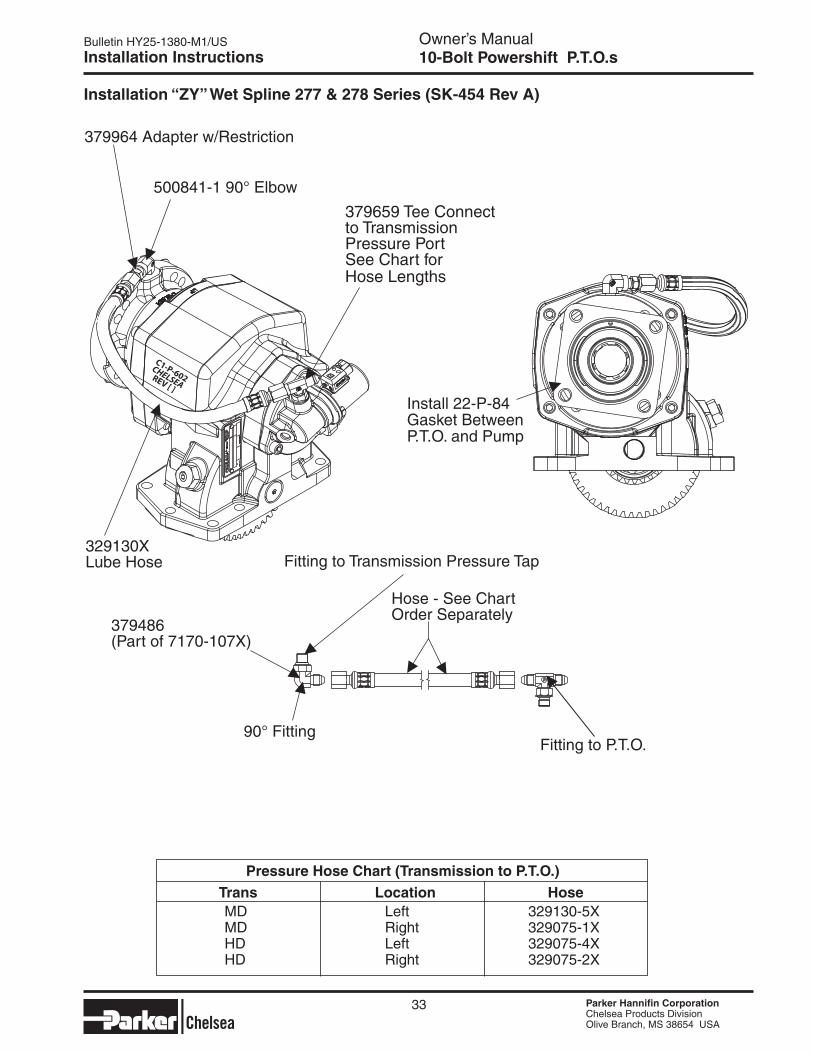
Installation Instructions 10-Bolt Powershift P.T.O.s
C1-P-602CHELSEAREV [ ]
Installation “ZY” Wet Spline 277 & 278 Series (SK-454 Rev A)
Pressure Hose Chart (Transmission to P.T.O.) Trans Location Hose MD Left 329130-5X MD Right 329075-1X HD Left 329075-4X HD Right 329075-2X
Fitting to Transmission Pressure Tap
90° Fitting
379486 (Part of 7170-107X)
Fitting to P.T.O.
Hose - See ChartOrder Separately
329130X Lube Hose
379659 Tee Connect to Transmission Pressure PortSee Chart for Hose Lengths
Install 22-P-84 Gasket Between P.T.O. and Pump
379964 Adapter w/Restriction
500841-1 90° Elbow
Parker lchelsea

Bulletin HY25-1380-M1/US Owner’s Manual
Parker Hannifin CorporationChelsea Products DivisionOlive Branch, MS 38654 USA
34
Installation Instructions
269 & 278 Series Installation Mounting Kit Instructions (SK-355 Rev B)
10-Bolt Powershift P.T.O.s
Installing Rotatable FlangesThe rotatable flange is shipped loose with the P.T.O. units for ease of installation. After determining the flange position, attach the flange to the P.T.O. bearing cap using the capscrews provided in the bag kit. Bag kit number 328170-207X (6-bolt family) will contain (3) capscrews (378447-6) and 328170-208X (277 Series) will contain (4) capscrews for attaching the flange to the P.T.O. bearing cap.After installing the capscrews make sure to torque the screws to 16-20 Lbs. ft.Consideration should be taken on the size and weight of the pump being installed. (see pages 3 and 4)
RA Flange Shown
NOTe: Reinstalling or tightening of a rotatable flange after it has become loose is not recommended. If a P.T.O. has run for a length of time after the flange has become loose, the flange and / or bearing cap may not be to manufacturing tolerance.
NOTe: P.T.O. Models 269 & 278 Guide pins 379451 may be removed after assembly and replaced with 379453-10 capscrews.
NOTe: Models 267, 277, 859 & 867 guide pins cannot be removed.
Dowel Pin Location if installing P.T.O. on Right Side (Curb Side) of Transmission.
NOTe: Install Shorter 379453-8 capscrews Under Barrel of P.T.O. Housing in Either Hole Depending on Housing Orientation.
Dowel Pin Locations if installing P.T.O. on Left Side (Street Side) of Transmission.
▼
▼▼
▼
Parker lchelsea

Bulletin HY25-1380-M1/US Owner’s Manual
Parker Hannifin CorporationChelsea Products DivisionOlive Branch, MS 38654 USA
35
Installation Instructions
CAUTION: This vehicle is equipped with a Power Take-Off. Shut engine off before working on the Power Take-Off or getting below the vehicle. Consult the operating instructions before using the P.T.O. (See sun visor.)
POWER TAKE-OFF OPERATION — VEHICLE STATIONARY
Automatic Transmission with Powershift P.T.O.s
Engage the P.T.O. with the engine at idle speed.
NOTe: Powershift P.T.O.s: The engine must be at idle or below 1000 R.P.M. when the P.T.O. is en-gaged. See the transmission manufacturer’s instructions for special procedures.
IMPORTANT:Failure to follow the proper shifting or operating sequences will result in premature P.T.O. failure with possible damage to other equipment.
Warning: Cold Weather Operation of Powershift P.T.O.s
During extreme cold weather operation [32° F (0° C) and lower], a disengaged Powershift Power Take-Off can momentarily transmit high torque that will cause unexpected output shaft rotation. This is caused by the high viscosity of the transmission oil when it is extremely cold. As slippage occurs between the Power Take-Off clutch plates, the oil will rapidly heat up and the viscous drag quickly decreases.
The Power Take-Off output shaft rotation could cause unexpected movement of the driven equipment, resulting in serious personal injury, death, or equipment damage.
To avoid personal injury or equipment damage:
■ Driven equipment must have separate controls.
■ Driven equipment must be left in the disengaged position when not in operation.
■ Driven equipment must not be operated until the vehicle is allowed to warm up.
This symbol warns of possible personal injury.
P.T.O. Shifting Procedure & Precautions
10-Bolt Powershift P.T.O.s
A
A
Parker lchelsea

Notes
Parker Hannifin CorporationChelsea Products DivisionOlive Branch, MS 38654 USA
36
Parker lchelsea

Notes
Parker Hannifin CorporationChelsea Products DivisionOlive Branch, MS 38654 USA
37
Parker lchelsea

Bulletin HY25-1380-M1/US Owner’s Manual
Parker Hannifin CorporationChelsea Products DivisionOlive Branch, MS 38654 USA
38
Power Take-Off Maintenance
Due to the normal and sometime severe torsional vibrations that Power Take-Off units experience, operators should follow a set maintenance schedule for inspections. Failure to service loose bolts or Power Take-Off leaks could result in potential auxiliary Power Take-Off or transmission damage.
Periodic P.T.O. MAINTENANCE is required by the owner/operator to ensure proper, safe and trouble free operation.
Daily: Check all air, hydraulic and working mechanisms before operating P.T.O. Perform maintenance as required.
Monthly: Inspect for possible leaks and tighten all air, hydraulic and mounting hardware, if necessary. Torque all bolts, nuts, etc. to Chelsea specifications. Ensure that splines are properly lubricated, if applicable. Perform maintenance as required.
With regards to the direct mounted pump splines, the P.T.O. requires the application of a specially formulated anti-fretting, high pressure, high temperature grease. The addition of the grease has been proven to reduce the effects of the torsional vibrations, which result in fretting corrosion on the P.T.O. internal splines as well as the pump external splines. Fretting corrosion appears as a “rusting and wearing” of the pump shaft splines. Severe duty applications, which require long P.T.O. running times and high torque may require more frequent regreasing. Applications such as Utility Trucks that run continuously and are lightly loaded also require frequent regreasing due to the sheer hours of running time. It is important to note that service intervals will vary for each and every ap-plication and is the responsibility of the end user of the product. Chelsea also recommends that you consult your pump owners manuals and technical services for their maintenance guidelines. Fretting corrosion is caused by many factors and without proper maintenance; the anti-fretting grease can only reduce its effects on components.
Chelsea offers the grease to our customers in two packages. The first is a 5/8 fluid ounce tube (379688), which is included with every applicable P.T.O., and the second is a 14-ounce grease cartridge (379831). Chelsea also offers greaseable shafts for most all output designators. Warranty: Failure to comply entirely with the provisions set forth in the appropriate Owner’s Manual will result in voiding of ALL Warranty consideration.
Power Take-Off Maintenance 10-Bolt Powershift P.T.O.s
Parker lchelsea

The items described in this document and other documents or descriptions provided by Parker Hannifin Corporation, its subsidiaries and its autho-rized distributors are hereby offered for sale at prices to be established by Parker Hannifin Corporation, its subsidiaries and its authorized distributors. This offer and its acceptance by any customer ("Buyer") shall be governed by all of the following Terms and Conditions. Buyer’s order for any such items, when communicated to Parker Hannifin Corporation, its subsidiary or an authorized distributor ("Seller") verbally or in writing, shall constitute acceptance of this offer.
8. Buyer’s Property: Any designs, tools, patterns, materials, drawings, confidential information or equipment furnished by Buyer or any other items which become Buyer’s property, may be considered obsolete and may be destroyed by Seller after two (2) consecutive years have elapsed without Buyer placing an order for the items which are manufactured using such property, Seller shall not be responsible for any loss or damage to such property while it is in Seller’s possession or control.9. Taxes: Unless otherwise indicated on the face hereof, all prices and charges are exclusive of excise, sales, use, property, occupational or like taxes which may be imposed by any taxing authority upon the manufacture, sale or delivery of the items sold hereunder. If any such taxes must be paid by Seller or if Seller is liable for the collection of such tax, the amount thereof shall be in addition to the amounts for the items sold. Buyer agrees to pay all such taxes or to reimburse Seller therefore upon receipt of its invoice. If Buyer claims exemption from any sales, use or other tax imposed by any taxing authority, Buyer shall save Seller harmless from and against any such tax, together with any interest or penalties thereon which may be assessed if the items are held to be taxable.10. Indemnity For Infringement of Intellectual Property Rights: Seller shall have no liability for infringement of any patents, trademarks, copyrights, trade dress, trade secrets or similar rights except as provided in this Part 10. Seller will defend and indemnify Buyer against allegations of infringement of U.S. Patents, U.S. Trademarks, copyrights, trade dress and trade secrets (hereinafter ‘Intellectual Property Rights’). Seller will defend at its expense and will pay the cost of any settlement or damages awarded in an action brought against Buyer based on an allegation that an item sold pursuant to this contract infringes the Intellectual Property Rights of a third party. Seller’s obligation to defend and indemnify Buyer is contingent on Buyer notifying Seller within ten (10) days after Buyer becomes aware of such allegations of infringement, and Seller having sole control over the defense of any allegations or actions including all negotiations for settlement or compromise. If an item sold hereunder is subject to a claim that it infringes the Intellectual Property Rights of a third party, Seller may, at its sole expense and option, procure for Buyer the right to continue using said item, replace or modify said item so as to make it noninfringing, or offer to accept return of said item and return the purchase price less a reasonable allowance for depreciation. Notwithstanding the foregoing, Seller shall have no liability for claims of infringement based on information provided by Buyer, or directed to items delivered hereunder for which the designs are specified in whole or part by Buyer, or infringements resulting from the modification, com-bination or use in a system of any item sold hereunder. The foregoing provisions of this Part 10 shall constitute Seller’s sole and exclusive liability and Buyer’s sole and exclusive remedy for infringement of Intel-lectual Property Rights.If a claim is based on information provided by Buyer or if the design for an item delivered hereunder is specified in whole or in part by Buyer, Buyer shall defend and indemnify Seller for all costs, expenses or judgments resulting from any claim that such item infringes any patent, trademark, copyright, trade dress, trade secret or any similar right.11. Force Majeure: Seller does not assume the risk of and shall not be liable for delay or failure to perform any of Seller’s obligations by reason of circumstances beyond the reasonable control of Seller (hereinafter ‘Events of Force Majeure’). Events of Force Majeure shall include without limitation, accidents, acts of God, strikes or labor disputes, acts, laws, rules or regulations of any government or government agency, fires, floods, delays or failures in delivery of carriers or suppliers, shortages of materials and any other cause beyond Seller’s control.12. entire Agreement/Governing Law: The terms and conditions set forth herein, together with any amendments, modifications and any different terms or conditions expressly accepted by Seller in writing, shall constitute the entire Agreement concerning the items sold, and there are no oral or other representations or agreements which pertain there/to. This Agreement shall be governed in all respects by the law of the State of Ohio. No actions arising out of the sale of the items sold hereunder or this Agreement may be brought by either party more than two (2) years after the cause of action accrues. 10/09-P
1. Terms and Conditions of Sale: All descriptions, quotations, pro-posals, offers, acknowledgments, acceptances and sales of Seller’s products are subject to and shall be governed exclusively by the terms and conditions stated herein. Buyer’s acceptance of any offer to sell is limited to these terms and conditions. Any terms or conditions in addi-tion to, or inconsistent with those stated herein, proposed by Buyer in any acceptance of an offer by Seller, are hereby objected to. No such additional, different or inconsistent terms and conditions shall become part of the contract between Buyer and Seller unless expressly accepted in writing by Seller. Seller’s acceptance of any offer to purchase by Buyer is expressly conditional upon Buyer’s assent to all the terms and condi-tions stated herein, including any terms in addition to, or inconsistent with those contained in Buyer’s offer, Acceptance of Seller’s products shall in all events constitute such assent.2. Payment: Payment shall be made by Buyer net 30 days from the date of delivery of the items purchased hereunder. Amounts not timely paid shall bear interest at the maximum rate permitted by law for each month or portion thereof that the Buyer is late in making payment. Any claims by Buyer for omissions or shortages in a shipment shall be waived un-less Seller receives notice thereof within 30 days after Buyer’s receipt of the shipment.3. Delivery: Unless otherwise provided on the face hereof, delivery shall be made F.O.B. Seller’s plant. Regardless of the method of deliv-ery, however, risk of loss shall pass to Buyer upon Seller’s delivery to a carrier. Any delivery dates shown are approximate only and Seller shall have no liability for any delays in delivery.4. Warranty: Seller warrants that certain Products, namely PTOs, SEMs, and Wet Line Kits sold hereunder shall be free from defects in material or workmanship for a period of twenty four months from the date of delivery to Buyer. Seller warrants that certain Products namely Pumps, and Hydraulic Accessories shall be free from defects in material or workmanship for a period of eighteen months from the date of delivery to the Buyer. The prices charged for Seller's products are based upon the exclusive limited warranty stated above, and upon the following disclaimer: DISCLAIMeR OF WARRANTY: THIS WARRANTY COMPRISeS THe SOLe AND eNTIRe WARRANTY PeRTAINING TO PRODUCTS PROVIDeD HeReUNDeR. SeLLeR DISCLAIMS ALL OTHeR WARRANTIeS, eXPReSS AND IMPLIeD, INCLUDING MeRCHANTABILITY AND FITNeSS FOR A PARTICULAR PURPOSe.5. Limitation Of Remedy: SeLLeR’S LIABILITY ARISING FROM OR IN ANY WAY CONNeCTeD WITH THe ITeMS SOLD OR THIS CONTRACT SHALL Be LIMITeD eXCLUSIVeLY TO RePAIR OR RePLACeMeNT OF THe ITeMS SOLD OR ReFUND OF THe PURCHASe PRICe PAID BY BUYeR, AT SeLLeR’S SOLe OPTION. IN NO eVeNT SHALL SeLLeR Be LIABLe FOR ANY INCIDeNTAL, CONSeQUeNTIAL OR SPeCIAL DAMAGeS OF ANY KIND OR NATURe WHATSOeVeR, INCLUDING BUT NOT LIMITeD TO LOST PROFITS ARISING FROM OR IN ANY WAY CONNeCTeD WITH THIS AGReeMeNT OR ITeMS SOLD HeReUNDeR, WHeTHeR ALLeGeD TO ARISe FROM BReACH OF CONTRACT, eXPReSS OR IMPLIeD WARRANTY, OR IN TORT, INCLUDING WITHOUT LIMITATION, NeGLIGeNCe, FAILURe TO WARN OR STRICT LIABILITY.6. Changes, Reschedules and Cancellations: Buyer may request to modify the designs or specifications for the items sold hereunder as well as the quantities and delivery dates thereof, or may request to cancel all or part of this order, however, no such requested modification or cancellation shall become part of the contract between Buyer and Seller unless accepted by Seller in a written amendment to this Agreement. Acceptance of any such requested modification or cancellation shall be at Seller’s discretion, and shall be upon such terms and conditions as Seller may require.7. Special Tooling: A tooling charge may be imposed for any special tooling, including without limitation, dies, fixtures, molds and patterns, acquired to manufacture items sold pursuant to this contract. Such special tooling shall be and remain Seller’s property notwithstanding payment of any charges by Buyer. In no event will Buyer acquire any interest in apparatus belonging to Seller which is utilized in the manufacture of the items sold hereunder, even if such apparatus has been specially converted or adapted for such manufacture and notwithstanding any charges paid by Buyer. Unless otherwise agreed, Seller shall have the right to alter, discard or otherwise dispose of any special tooling or other property in its sole discretion at any time.
Offer of Sale
Parker Hannifin CorporationChelsea Products DivisionOlive Branch, MS 38654 USA
39
Parker lchelsea

Parker Hannifin CorporationChelsea Products Division8225 Hacks Cross RoadOlive Branch, Mississippi 38654 USATel: (662) 895-1011Fax: (662) 890-5379www.parker.com/chelsea
FP 03/10 4.5M
Parker