fttx rf/video overlay - dkt home · pdf filefeatures and benefits lower network operating...
TRANSCRIPT

fttx rf/video overlay
RF O
VERL
AY V
2

DKT designs and manufactures optical and coaxial products for professional broadband operators and service providers. DKT’s unique product line, combined with extensive experience from many years in the industry, makes it a strong partner.
The company was founded in 1977, and is family owned. Its headquarters are in Denmark and has subsidiaries in Sweden, Finland and Germany.
Via a strong network of distributors and subsidiaries, customers are served in most parts of Europe. It has always been DKT’s philosophy to challenge the status quo and look for improvements to benefit the customers. This has lead us to unique products that add value to the installation as well as network performance.
DKT’s missionDKT develops and creates a series of products for broadband networks within 3 major groups: Coax distribution, FTTX (Fiber technology) and Home Networks.
The vision is to create the best solutions and products to connect Europe to high-speed broadband with focus on quality and innovation.
DKT will actively contribute to exceed the expectations concerning deployment of fast broadband in the 2020 plan of the EU commission, which will increase living standards and competitiveness across Europe.
Scan the QR tag to view the latest PDF version of this brochure.
about dkt
Specifications are subject to change without notice. DKT is not liable for any misprints or errors.
Solution introduction ......................................................................... 3
Features and benefits ........................................................................ 4
Design solution ................................................................................ 5
Laser transmitters - general ................................................................ 7
Laser transmitters - 1550 nm DFB .......................................................... 8
Laser transmitters - 1550 nm externally modulated ....................................9
Erbium doped fibre amplifiers (EDFA) .................................................... 11
EDFA - characteristics ..................................................................... 12
EDFA - ordering information .............................................................. 13
Single mode dual window couplers (1x2 way) .......................................... 14
Single mode tree couplers (1x3 to 1x64 way) .......................................... 15
High density FTTH splitter, 19-inch rack type .......................................... 16
FTTH splitter, 19-inch rack type with 64x WDM module .............................. 17
Fibre-to-the-Building (FTTB) nodes ...................................................... 19
Fibre-to-the-Home (FTTH) nodes ......................................................... 21
PoP-kit solution ............................................................................. 22

3
solution introduction
Introduction
With the ever increasing demand from consumers concerning bandwidth, fibre networks are being deployed in an increasing rate, pushing ever further towards the subscriber’s premises. This development is not new, or unique for broadband network. However when the fiber is installed, our experience is that many subscribers wish to continue to utilize the existing coaxial network in the house, avoiding new cabling and additional boxes. By choosing an RF overlay in the network, DKT’s experience shows that a higher customer penetration rate and customer satisfaction can be achieved compared to IP-only video services.
The DKT RF/video overlay solution can be utilized on both active Ethernet (P2P) and passive optical networks (PON), by adding an extra wavelength being broadcast on the fiber. Both amplifiers and transmitters can be remotely managed and monitored, allowing troubleshooting and adjustment without having a technician in the field.
The video service is considered to be the most important service in a broadband network today, and its success will be determined on how it is perceived by the end-user. RF/video overlay will improve the success due to easy in-home distribution and used in combination with IP video.
We see the RF video service as a supplement to an optional IP video service. The standard TV package will be RF, which is easy for the consumer to “handle” as the coaxial network already installed in the home can be used without any modifications. Additional TV services can then be offered on IP. Since 1999 we have been specialists in RF overlay in fiber optical networks and we are happy to share our knowledge in this area.
To summarize, what does this imply?
Increased service level and higher level of customer satisfaction• Stabile services. Happy customers and reduced churn as a result.
Increased revenue and ARPU• Due to increased flexibility with both IP and RF signals, all customers can easily be served with video
services.
Attractive return on investment• Stretch investment budget across several years.• No need for full scale implementation - can be done ongoing.
Improved OPEX• RF services are very robust and the technology is mature which, results in very low maintenance and
low customer support.• As there is no set-top box, the depreciation is systematically reduced.
FHT GATEWAY
Head-end FTTH & FTTBSpecific brochure for FTTH
gateways is available
AmplifiersTransmitters Splitters
OLT
The RF/video overlayThe gray area below displays what DKT considers the RF overlay. This is covered in the brochure.

features and benef its
Lower network operating costs
The RF overlay solution offers end-to-end management and status monitoring on all active components via SNMP. Compared to traditional RF networks, the DKT solution supports a lower OPEX by optimizing total network operating costs and faster network troubleshooting. Furthermore, as signals can be transmitted further on fibre than traditional coaxial cable, the amount of active components in the network can be substantially reduced, resulting in fewer sources for defects. The solution can be managed remotely or locally on the individual front panels.
Stabile services
Our long experience with fibre technology gives us an advantageous position when evaluating quality at subcontractors, ensuring that only production facilities of the highest standard are chosen to manufacture our portfolio. Combined with the ability to create redundancy in both power supplies and transmission makes for an incredible uptime on the TV signal, which is key to increasing customer satisfaction, and thereby reducing both churn and maintenance cost.
Increased flexibility
By adding an RF overlay to the fiber network, it’s possible to service all potential customers on the network. By transmitting an RF signal that can be connected directly to all TVs after the optical/electrical conversion at the CPE. That way it is possible to utilize existing in-home coaxial networks to supply TV sets, and thereby avoiding set-top boxes and rewiring of the home. The ease of installation is a swaying factor for the discerning audience.
Accrual of investments (on CATV networks)
When implementing an RF overlay, it is not necessary to invest large sums (High CAPEX) initially. If Optical/Electrical nodes are being utilized, it’s possible to spread investments over a period of time, that does not need to be predefined as there is no expiration date on a partial implementation. The idea is simply to push the fibre closer to the customer, by replacing coaxial infrastructure with fiber, and thereby reducing the amount of amplifiers and other coaxial equipment. When implementation is finalized in an area, the optical/electrical nodes are removed from the network due to replacement of smaller CPE units, and are as such ready to be placed within a new network, starting the upgrade cycle once more.

5
design solution
PON RF overlay solutionThe RF signal is distributed from a standard RF head-end through an E/O 1550 nm laser transmitter. The RF signal is transported by a separate fibre network to the PoP station. Optical protection of the primary and secondary signal routes is optional through a protection switch, either included in an EDFA or as a standalone device. A WDM coupler combines the RF signal with the data traffic from the PoP OLT, which uses a different wavelength (1310/1490 nm), putting three wavelengths on the same fibre PON and distributing them downstream through the splitters to the customer’s ONT/ONUs.
Point-to-Point (P2P), Active Ethernet RF overlay solutionThe RF signal is typically distributed from a standard RF head-end through an electrical to optical 1550 nm laser transmitter. The RF signal is transported by a separate fibre network to the PoP station in the field. Optical protection of the primary and secondary signal routes is optional through a redundant failover switch, either included in an EDFA or as a standalone device. An EDFA amplifies the signal and distributes it through an optimized design of splitters to the P2P CPE.
The DKT RF overlay solution compliments active Ethernet networks as well as PON networks.
1:32 - 64
1:32 - 64
1:32 - 64
FHT GATEWAY
LT OPS EDFAPoPHEAD-END FTTx
1:32 - 64
1:32 - 64
1:32 - 64
FHT GATEWAY
LT OPS EDFAPOP
OLT
HEAD-END FTTx
LegendLT = Laser Transmitter, electrical to optical conversion unit.
OPS = Optical Protection Switch, an optical fail-over device, adding redundancy in the broadcasting.
EDFA = Erbium Doped Fibre Amplifier, amplification unit of optical forward path signals.
OLT = Optical Line Terminal, an OLT provides the interface between a PON and a service provider′s core network.
1:16 - 64
1:16 - 64
1:16 - 64FHT GATEWAY
DATA
1:16 - 64
1:16 - 64
1:16 - 64FHT GATEWAY
DATA
Access switches

Benefits
- Maximum performance- Stable operation- Simple plug-and-play- Easy installation- Easy network management via TELNET, HTTP & SNMP

7
laser transmitters
Product informationThe laser transmitters support today’s need for optical transmission of RF signals in modern fibre optical broadband networks. To complement Internet and voice applications, DKT provides unique solutions for RF transmission for long-haul and short-haul applications.
The product line consists of two different series, depending on the required signal transmission distance; thermally stabilised DFB isolated lasers for short-haul and externally modulated lasers for long-haul. Both lines can simultaneously transmit a high number of channels with superior performance.
Externally modulated transmitter (LTE)The transmitter takes advantage of advanced fibre dispersion compensation circuitry to provide exceptional CATV performance. It provides a cost-efficient, transport solution for medium to long distances.
• Handles conventional cable television as well as DVB-C and DVB-T formats.• Suitable for long-haul applications up to 90 km.• SBS suppression for optimized CSO and CTB over long-haul fibre lengths.
DFB laser transmitterThe DFB optical laser transmitter employs a high performance thermally stabilisedDFB, a low-chirp isolated laser to transmit 1550 nm CATV signals.
• Handles conventional cable television as well as DVB-C and DVB-T formats.• Suitable for <10 km fibre links and short-haul FTTH access networks.• Possible >30 km reach on 1550 nm dispersion shifted fibres.
FHT GATEWAY
RF-Input LTE EDFA40 - 50 km
EDFA40 - 50 km
O/EConversion
RF-Input LTE EDFA< 10 km
O/EConversion
FHT GATEWAY

Optical and RF Data
Optical wavelength ITU grid channel (193,3 THz), 1550 nm range (1550,92 nm)
Optical output power options (mW) 6, 8, 10
Optical connectors SC/APC, E2000/APC, FC/APC
RF bandwidth (MHz) 45...1000
RF input level (dBµV) 85 at 4 % OMI
RF flatness (dB) ± 0,75
RF gain control (dB) -15...5
RF input (Ω) 75 SCTE F-type
RF test point -20 dB ± 1 dB, 75 Ohm Mini-SMB
Link performance (measured at 0 dBm optical input, 1550 nm 10 km SMF and 4% OMI)42 CENELEC channels (as per EN50083-3)
Carrier-to-Noise Ratio (CNR) (dB) > 53
Composite Second Order (CSO) (dB) > 55
Composite Triple Beat (CTB) (dB) > 61
General
Power 90 ~ 264 VAC 50 ~ 60 Hz
Power Consumption (W) 46
Operating temperature (°C ) 0...45
Dimensions (H x W x D mm) 44 x 483 x 360
Weight (kg) 5
Craft port (management system) USB on front panel
Network port (SNMP/HTTP) 10BaseT
Declaration of conformity CE: EN50083-2
Product information
The optical transmitter model LT1550 employs a high performance thermally stabilised DFB, a low-chirp isolated laser to transmit CATV signals. Operating on a specific optical wavelength in the ITU-DWDM grid, the unit suits single-mode optical fibre networks with or without Dense Wavelength Division Multiplexing (DWDM).
Designed for high channel loading and superior performance, DKT can guarantee distances with this transmitter of up to 10 km, and with the correct fibre quality distances of up to 30 km.
LT1550 optical transmitters incorporate a comprehensive alarm and status monitoring system. This is for all laser operating parameters such as DC Laser Bias Current, Cooler Current and Optical Output Power.
The data is simultaneously available on a front panel LCD display, on a USB connector and optionally via a HTTP/SNMP network module.
Features
- Analog InGaAsP DFB low-chirp laser with optical isolator and thermoelectric cooler.
- Handles conventional cable television as well as digital DVB-T or DVB-C formats.
- 45 ~ 1000 MHz forward path RF amplifier with automatic gain control (AGC) for a constant Optical Modulation Index (OMI).
- Automatic Peltier thermo-cooler control and automatic laser power control for constant laser temperature and optical output.
- Self-contained 19-inch subrack 1 RU with integrated universal mains power supply.
- Backlit LCD display provides status monitoring and control.
- Front panel mounted USB craft port with optional Ethernet port on the rear panel for SNMP/HTTP network management.
1550 nm dfb
Item no. Type no. Output power
64155 LT1550-06-33-R0-SC-S 6 mW
64158 LT1550-08-33-0-SC-SN 8 mW
64160 LT1550-10-1-33.SC-U 10 mW

9
1550 nm externally modulatedProduct information
The LTE153-6000 externally modulated laser transmitter for 1550 nm wavelengths is designed as a professional solution for long line CATV delivery. The unit delivers excellent performance on long-haul fibre with dispersion shifted to 1550 nm. The transmitter also operates very well in systems with legacy non-dispersion shifted fibres, optimised for 1310 nm.The transmitter provides a chirp-free mode of operation with a very narrow optical line width. This allows the use of 1550 nm wavelength for the transmission of broadband CATV, whilst maintaining excellent CNR, CSO and CTB performance throughout the network.The LTE153-6000 is packaged in a self-contained 19” sub rack housing of 1 RU, with lateral cooling and an option for dual, redundant, hot-swappable power supplies.The transmitter features field-adjustable SBS suppression to optimise performance for optical line drive levels between 14 dBm and 18 dBm. The standard unit operates on 1550 ± 5 nm with an option for DWDM lasers specified from the ITU grid. Multiple DWDM laser transmitters can be combined for transmission through a single optical amplifier.An integrated SNMP agent makes remote management and monitoring possible through an RJ45 network connection. A large LCD readout is provided for local management.
Features- Externally-modulated transmitter with low dispersion distortion.- RF pre-distortion circuit for excellent CSO and CTB performance with low distortion parameters.- Designed for long-haul applications, as well as for short-haul FTTH customer access networks.- Dual redundant universal mains hot-swappable power supplies.- Field-adjustable Stimulated Brillouin Scattering (SBS) suppression.- Integrated SNMP agent with RJ45 Ethernet port for remote monitoring.- Flat RF frequency response for 45 ~ 1003 MHz.- Dual optical outputs for 2 x 7 dBm.
Optical and RF Data
Optical wavelength 1550 ± 5 nm, ITU-grid available
Optical output power options (mW) 2 outputs 7.0/7.0
Optical connectors SC/APC
RF bandwidth (MHz) 45 - 1003
RF input level 15-20 dBmV or 75-80dBuV
RF flatness (dB) ± 0.75 @ 45 ~ 1003 MHz
RF input return loss ≥ 16 dB
RF input (Ω) 75
RF test point -20 dB ± 1 dB down from RF input
Link performance (measured at 0 dBm optical input, 1550 nm 65 km SMF and 4% OMI)60 PAL channels at 25 °C
SBS Suppression (dBm) 16
Carrier-to-Noise Ratio (CNR) (dB) > 53
Composite Second Order (CSO) (dB) > 65
Composite Triple Beat (CTB) (dB) > 65
General
Power Dual PSU, 90 ~ 265 VAC 50 ~ 60 Hz
Power Consumption (W) max. 65
Operating temperature (°C ) 0 - +45
Dimensions (H x W x D mm) 44 x 485 x 381
Weight (kg) 6
Network port (SNMP/HTTP) RJ45 with 10/100baseTx
Declaration of conformity CE: EN50083-2
Item no. Type no. Output power
64194 LTE153-6000-SA-1013 2 x 7 mW

Benefits
- Easy plug-and-play installation and operation- High power for dense FTTH subscriber applications- Simple network management via HTTP/SNMP- Many configuration possibilities- High reliability/high MTBF
11
Product information
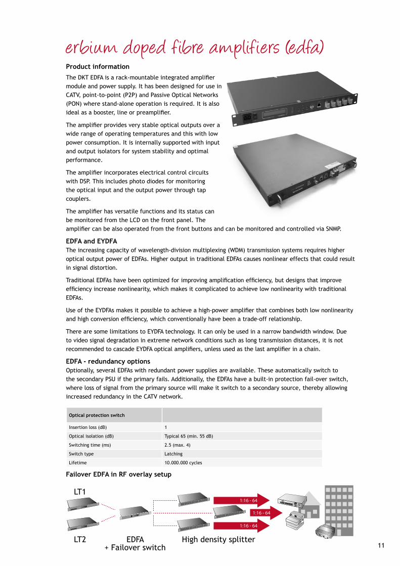
The DKT EDFA is a rack-mountable integrated amplifier module and power supply. It has been designed for use in CATV, point-to-point (P2P) and Passive Optical Networks (PON) where stand-alone operation is required. It is also ideal as a booster, line or preamplifier.
The amplifier provides very stable optical outputs over a wide range of operating temperatures and this with low power consumption. It is internally supported with input and output isolators for system stability and optimal performance.
The amplifier incorporates electrical control circuits with DSP. This includes photo diodes for monitoring the optical input and the output power through tap couplers.
The amplifier has versatile functions and its status can be monitored from the LCD on the front panel. The amplifier can be also operated from the front buttons and can be monitored and controlled via SNMP.
EDFA and EYDFAThe increasing capacity of wavelength-division multiplexing (WDM) transmission systems requires higher optical output power of EDFAs. Higher output in traditional EDFAs causes nonlinear effects that could result in signal distortion.
Traditional EDFAs have been optimized for improving amplification efficiency, but designs that improve efficiency increase nonlinearity, which makes it complicated to achieve low nonlinearity with traditional EDFAs.
Use of the EYDFAs makes it possible to achieve a high-power amplifier that combines both low nonlinearity and high conversion efficiency, which conventionally have been a trade-off relationship.
There are some limitations to EYDFA technology. It can only be used in a narrow bandwidth window. Due to video signal degradation in extreme network conditions such as long transmission distances, it is not recommended to cascade EYDFA optical amplifiers, unless used as the last amplifier in a chain.
EDFA - redundancy optionsOptionally, several EDFAs with redundant power supplies are available. These automatically switch to the secondary PSU if the primary fails. Additionally, the EDFAs have a built-in protection fail-over switch, where loss of signal from the primary source will make it switch to a secondary source, thereby allowing increased redundancy in the CATV network.
erbium doped f ibre amplif iers (edfa)
Optical protection switch
Insertion loss (dB) 1
Optical isolation (dB) Typical 65 (min. 55 dB)
Switching time (ms) 2.5 (max. 4)
Switch type Latching
Lifetime 10.000.000 cycles
1:16 - 64
1:16 - 64
1:16 - 64
FHT GATEWAY
LT1
LT2 EDFA+ Failover switch
High density splitter
Failover EDFA in RF overlay setup

* Test condition where Input power = 0 dBm at 1550 nm and measured within operating temperature range.
† Only applicable for item no.: 64656 - 64657
edfa - characteristicsOptical specifications 600-series 800-series
Optical wavelength (nm) 1545 to 1565 1530 to 1566
Optical input power (dBm)* 64814 and 64820: -5 to +10All other: -10 to +10 -5 to +10
Optical output power (dBm) See ordering information See ordering information
Accuracy of output power (dB) ± 0.5 ± 0.5
Uniformity maximum (dB) 1 1
Optical isolation (dB) > 30 > 30
Optical return loss (dB) > 45 > 40
Noise figure (dB)* < 5.5 < 5.5
Polarization mode dispersion (ps) 0.4 1.0
Polarization dependence gain (dB) 0.3 0.5
Pump leakage (dBm) -30 (At input and output) -30 (At input and output)
Optical connector type SC/APC, SMF SC/APC, SMF, other types available upon request
Electrical specifications
Power supply type 230 VAC 230 VAC or 48 VDC
Supply voltage AC (V) 100 - 240 (Frequency 50/60 Hz) 100 - 240 (Frequency 50/60 Hz)
Supply voltage DC (V) - 36 - 75
Number of power supplies 1 1 or 2
Mechanical specifications
Physical dimension (H x W x D mm) 43.6 x 483 x 25243.6 x 483 x 490 †
43.6 x 483 x 350 (1U)88 x 483 x 350 (2U)
General
Storage temperature (°C) -40 to +85 -40 to +85
Operating temperature (°C) -5 to 55 0 to 50
Storage humidity (%) 0 to 95 0 to 95
Operating relative humidity (%) 0 to 85 (Non-condensing) 0 to 95 (Non-condensing)
Communications connectors
RS232
64652 to 64655: 1 port, DB9 con-nector (38400 bps baud rate)
All other: 1 port RJ45 connector (38400 bps baud rate)
1 port, RJ45 connector (38400 bps baud rate)
Ethernet 1 port, RJ45 connector (10/100 Mbps)
1 port, RJ45 connector (10/100 Mbps)
Optical specifications EYDFA
Optical wavelength (nm) 1545 to 1560
Optical input power (dBm)* -5 to +10
Noise figure (dB) Typ. 5
Uniformity (max. dB) 1.5
Optical isolation (dB) > 30
General
Operating temperature range (°C) 0 - 50
Dimensions (H x W x D mm) 88 x 350 x 304
Differences in 880-series specifications from 800-series

13
* Measured maximum consumption.
edfa - ordering information
Item no. Type no. Output power Number of outputs
Power consumption (W)* Height Notes
64821 EDFA-17-DUAL-SA-01-S 17 dBm 1 < 20 1U Dual PSU, front connectors
64824 EDFA-17-DUAL-SA-04-S 17 dBm 4 < 30 1U Dual PSU, front connectors
64825 EDFA-19-DUAL-SA-08-S 19 dBm 8 < 65 2U Dual PSU, front connectors
64826 EDFA-21-DUAL-SA-04-S 21 dBm 4 < 55 1U Dual PSU, front connectors
64827 EDFA-21-DUAL-SA-08-S 21 dBm 8 < 80 2U Dual PSU, front connectors
64830 EDFA-21-DUAL-SA-01-S 21 dBm 1 < 25 1U Dual PSU, front connectors
64831 EDFA-17-DUAL-SA-01-S 17 dBm 1 < 20 1U Dual PSU, front connectors
64832 EDFA-17-DUAL-SA-02-S 17 dBm 2 < 25 1U Dual PSU, front connectors
64833 EDFA-17-DUAL-SA-03-S 17 dBm 3 < 25 1U Dual PSU, front connectors
64834 EDFA-17-DUAL-SA-04-S 17 dBm 4 < 30 1U Dual PSU, front connectors
64835 EDFA-19-DUAL-SA-04-S 19 dBm 4 < 45 1U Dual PSU, front connectors
64836 EDFA-21-DUAL-SA-04-S 21 dBm 4 < 55 1U Dual PSU, front connectors
64837 EDFA-21-DUAL-SA-08-S 21 dBm 8 < 80 1U Dual PSU, front connectors
800-series
Item no. Type no. Output power Number of outputs
Power consumption (W)* Height Notes
64652 EDFA-17-220-SA-01-S 17 dBm 1 < 30 1U Compact depth
64653 EDFA-17-220-SA-02-S 17 dBm 2 < 30 1U Compact depth
64654 EDFA-17-220-SA-03-S 17 dBm 3 < 30 1U Compact depth
64655 EDFA-17-220-SA-04-S 17 dBm 4 < 30 1U Compact depth
64656 EDFA-19-220-SA-04-S 19 dBm 4 < 75 1U Web management
64657 EDFA-21-220-SA-04-S 21 dBm 4 < 75 1U Web management
64814 EDFA-17-230-SA-04-S 17 dBm 4 < 45 1U Front connectors
64820 EDFA-21-230-SA-04-S 21 dBm 4 < 50 1U Front connectors
600-series
Applications
- Long-haul Telecommunications - CATV Systems- P2P/PON FTTH/FTTB Networks
Features
- High saturation output power- CATV field–proven low noise figure- Wide input dynamic range- Stable output power over wide temperature range- Control and monitoring with SNMP
Item no. Type no. Output power Number of outputs
Power consumption (W)* Height Notes
64881 EYDFA-21-DUAL-SA-04 21 dBm 4 < 55 1U Dual PSU, front connectors
64882 EYDFA-21-DUAL-SA-08 21 dBm 8 < 80 2U Dual PSU, front connectors
64883 EYDFA-21-DUAL-SA-16 21 dBm 16 < 46 2U Dual PSU, front connectors
64884 EYDFA-19-DUAL-SA-32 19 dBm 32 < 50 2U Dual PSU, front connectors
880-series
Other types available upon request

single mode dual window couplers (1x2 way)Product information
Optical couplers are often used in network design, either for tap-off or to divide/combine optical signals. For this purpose DKT can offer a range of 1x2 couplers with a splitting ratio ranging from 5/95 to 50/50 using fused technology.
These couplers feature low insertion loss and are specially designed for broadband networks as well as long-haul transmission systems. SC/APC are available as standard connectors. Other connectors can be ordered upon request.
Features
- Complete range from 5/95 - 50/50- High stability- Low insertion loss- High quality connectors- High network uptime
Item no. Type no. Coupler ratio % Typical insertion loss (dB) *
69802 OSP-S-5050-SC/APC 50 / 50 3.1
69806 OSP-S-5545-SC/APC 45 / 55 3.6 / 2.7
69811 OSP-S-6040-SC/APC 40 / 60 4.3 / 2.3
69816 OSP-S-6535-SC/APC 35 / 65 4.7 / 2.0
69821 OSP-S-7030-SC/APC 30 / 70 5.5 / 1.6
69826 OSP-S-7525-SC/APC 25 / 75 6.1 / 1.4
69831 OSP-S-8020-SC/APC 20 / 80 7.5 / 1.0
69836 OSP-S-8515-SC/APC 15 / 85 8.4 / 0.8
69841 OSP-S-9010-SC/APC 10 / 90 10.6 / 0.5
69846 OSP-S-9505-SC/APC 5 / 95 13.5 / 0.3
* Measurements without connectors
Parameter Data
Uniformity (dB) max. 0.6
Polarization sensitivity (dB) 0.2
Operating wavelength (nm) 1260...1360 & 1430...1600
Return loss / Directivity (dB) ≥ 55
Operation temperature range (°C) -40...85
Connector type SC/APC, Other types available upon request
Fibre type G.652.D 9/125/3000 µm
Port configuration 1 x 2
Dimensions (H x W x D mm) 98 x 14 x 8.5

15
single mode tree couplers (1x3 to 1x64 way)Product information
Tree couplers are very often used to divide or combine signals from different locations in an optical network. For these applications DKT has a wide range of cou-plers to split and combine signals from 1x3 lines up to 1x64 lines.
The couplers feature low insertion loss, low excess loss, high directivity and are specially designed for long-haul telecommunications, CATV systems and LAN networks.
SC/APC is used as standard. Other connector types are available upon request.
Features
- High stability- Low insertion loss- High quality connectors- High network uptime- Option for 19-inch 1HU
Parameter Data
Uniformity (dB) 0.10 to 1.2 (1x4), 1.8 (1x8), 2.4 (1x16), 3.0 (1x32)
Polarization sensitivity (dB) 0.10 to 0.4 (1x4), 0.6 (1x8), 0.8 (1x16), 1.0 (1x32)
Operating wavelength (nm) 1260...1360 & 1430...1600
Return loss / Directivity (dB) ≥ 55
Operation temperature range (°C) -40...85
Connector type SC/APC, Other types available upon request
Fibre type G.652.D 9/125/3000 µm
Dimensions (H x W x D mm) 100 x 80 x 8.5
Item no. Type no. Port configuration Typical insertion loss (dB)
69851 OSP-S-03-28-SC/APC 1 x 3 4.9
69856 OSP-S-04-28-SC/APC 1 x 4 6.2
69866 OSP-S-06-28-SC/APC 1 x 6 8.0
69886 OSP-S-08-28-SC/APC 1 x 8 9.3
69891 OSP-S-16-28-SC/APC 1 x 16 12.4
69895 OSP-S-24-28-SC/APC 1 x 24 15.6
69896 OSP-S-32-28-SC/APC 1 x 32 17.0
Other types available upon request

high density ftth splitter, 19-inch rack typeProduct information
The OSP19-SC/APC is an optical splitter with SC/APC termination in a 19-inch 1U rack.
In front of the chassis there is features a fiber management tray, making it easier to handle high quantities of fibres in the rack. Additionally, the mounting brackets are depth adjustable, allowing more flexibility with different rack cabinets.
Tree-couplers are very often used to divide or combine signals from different locations in an optical network. For these applications DKT has a range of couplers to split and combine signals from 1x16 lines and up to 1x64 lines in a one height unit.
These products feature low insertion loss, high directivity and are specially designed for CATV communication and FTTH/FTTx communication networks.
Features
- High stability- Low insertion loss- 19-inch mounting- High quality connectors- High network uptime
19-inch rack optical splitter
Type 16-way 32-way 64-way
Item no. 69703 69700 69710
Typical insertion loss (dB) ≤ 14.0 ≤ 17.1 ≤ 21.5
Typical uniformity (dB) ≤ 1.5 ≤ 1.5 ≤ 2.5
Polarization dependent loss (dB) ≤ 0.3 ≤ 0.3 ≤ 0.4
Operating wavelength (nm) 1260 ~ 1610 1260 ~ 1610 1260 ~ 1610
Return loss / Directivity (dB) ≥ 55 ≥ 55 ≥ 55
Operation temperature range (°C) -40...85 -40...85 -40...85
Port configuration 1 x 16 1 x 32 1 x 64
Connector type SC/APC SC/APC SC/APC
Dimensions (H x W x D mm) 44 x 483 x 170 44 x 483 x 170 44 x 483 x 170
Empty 19” housing for custom configuration is also available.
The housing has 25 ports, one marked as “IN” and 24 ports numbered from 1-24. The package also contains screws for fastening adaptors.
Type* Item no.
Housing 69799
SC/APC Adaptor 67200
SC/PC Adaptor 67202
LC/APC Duplex Adaptor 67207
*Other types available upon request
Other types available upon request
17
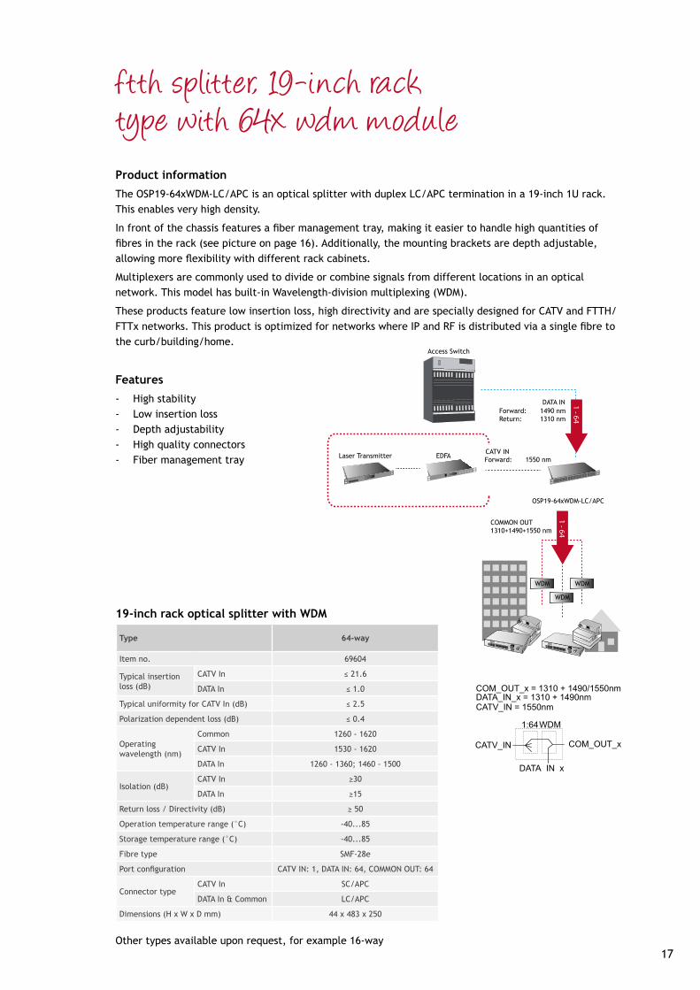
ftth splitter, 19-inch rack type with 64x wdm moduleProduct information
The OSP19-64xWDM-LC/APC is an optical splitter with duplex LC/APC termination in a 19-inch 1U rack. This enables very high density.
In front of the chassis features a fiber management tray, making it easier to handle high quantities of fibres in the rack (see picture on page 16). Additionally, the mounting brackets are depth adjustable, allowing more flexibility with different rack cabinets.
Multiplexers are commonly used to divide or combine signals from different locations in an optical network. This model has built-in Wavelength-division multiplexing (WDM).
These products feature low insertion loss, high directivity and are specially designed for CATV and FTTH/FTTx networks. This product is optimized for networks where IP and RF is distributed via a single fibre to the curb/building/home.
Features
- High stability- Low insertion loss- Depth adjustability- High quality connectors- Fiber management tray
Type 64-way
Item no. 69604
Typical insertion loss (dB)
CATV In ≤ 21.6
DATA In ≤ 1.0
Typical uniformity for CATV In (dB) ≤ 2.5
Polarization dependent loss (dB) ≤ 0.4
Operatingwavelength (nm)
Common 1260 - 1620
CATV In 1530 - 1620
DATA In 1260 - 1360; 1460 - 1500
Isolation (dB)CATV In ≥30
DATA In ≥15
Return loss / Directivity (dB) ≥ 50
Operation temperature range (°C) -40...85
Storage temperature range (°C) -40...85
Fibre type SMF-28e
Port configuration CATV IN: 1, DATA IN: 64, COMMON OUT: 64
Connector typeCATV In SC/APC
DATA In & Common LC/APC
Dimensions (H x W x D mm) 44 x 483 x 250
19-inch rack optical splitter with WDM
FHT GATEWAY
1 - 64
Laser Transmitter
Access Switch
EDFACATV IN
DATA IN
Forward: 1550 nm
OSP19-64xWDM-LC/APC
1 - 64
FHT GATEWAY
COMMON OUT1310+1490+1550 nm
WDM
WDM
WDM
Forward: 1490 nmReturn: 1310 nm
Other types available upon request, for example 16-way

Advantages
- Value line – compact deep fibre optical node- High system performance – high levels/low noise - Output splitter incorporated within the node - Single compact unit, housing fibre optic receiver and a versatile RF amplifier - Competitive price/performance

19
f ibre-to-the-building (fttb) nodesProduct Introduction
The product line consists of two different series. Firstly, the AO series, which is a compact and versatile FTTx node for two-way transmission. It provides an efficient way to manage and control the roll-out of projects and new services. The all-in-one active element delivers high output levels for distribution or low level output for trunk deployments.
Secondly, the OE series, which is a deep fibre FTTC node ideal for multimedia applications. This pushes fibre directly to the curb in densely populated areas. Whilst operating with a low power consumption level, this all-in-one element delivers high output levels for distribution in any broadband HFC network environment.
Both series have a variety of configuration possibilities and can be expanded to meet the future needs of a growing and changing network.
Separate brochure is available.
Forward path, optical section AO 801V1 OE 801H1
Optical wavelength 1290 - 1600 nm 1290-1600 nm
Optical input power level -6 to +2 dBm -6 to +2 dBm
Equivalent current noise @ 47 / 862 MHz 8 / 6 pA/√Hz 8 / 6 pA/√Hz
Forward path, coaxial section
Bandwidth (depending on diplexer modules) 47 - 862 MHz 47-862 MHz
Output level - high gain (optical link specifications) 102-112 dBμV 100-110 dBμV
CTB (42 ch CENELEC) @ 0 dBm / 4.5% OMI 62 dB @ 110 dBμV 62 dB @ 110 dBμV
CSO (42 ch CENELEC) @ 0 dBm / 4.5% OMI 65 dB@ 110 dBμV 65 dB @ 110 dBμV
Output level - low gain (optical link specifications) 94 - 106 dBμV -
CTB (42 ch CENELEC) @ 0 dBm / 4.5% OMI 68 dB @ 100 dBμV -
CSO (42 ch CENELEC) @ 0 dBm / 4.5% OMI 65 dB @ 100 dBμV -
Return path
Bandwidth (depending on diplexer modules) 5-65 MHz 5-65 MHz
General
Line power, voltage 24-65 VAC -
Line power, current 1080-450 mA -
Mains power, voltage 175-260 VAC 175-260 VAC
Power consumption (incl. return path) 19 W 15 W
Internally used optical connector SC/APC SC/APC
Coaxial outputs PG11 PG11
Physical
Dimension (H x W x D) 200 x 180 x 82 mm 200 x 180 x 82 mm
Weight 2 kg 2 kg
Note: all specifications are with 0 dB link modules. If other modules are inserted, then please correct for insertion loss.
Ordering information
Type no. AOL 801 V1 AOM 801 V1 OEM 801 H1
Item no. 65807 65801 65804
Power supply Line Mains Mains

Advantages
- The easiest way to add TV/FM services to an FTTH network- Cost optimized - cost per TV/FM channel / service - An open opportunity to add IP services at any time- No need for set-top boxes- Easy installation - ease of use - plug and play - Services: TV/FM, DVB-C, DVB-T, DAB

21
f ibre-to-the-home (ftth) cpe gatewayProduct Introduction
There are two models of FTTH gateways. The 796xx series is a full-size gateway, ranging from management to Multiport Ethernet and VoIP. The 797xx series is a very compact gateway, offering the most basic features for optical to electrical conversion.
Both product series follow the philosophy of utilizing a “two-box” rather than an “all-in-a-box” solution. It is DKT’s belief to separate the OSI layers 1, 2 and 3. This results in a cost-efficient base installation, allows for home network scalability and also permits several independent service providers. This ensures that the base installation does not require upgrading to comply with wireless technology changes and other technologies.
This brochure provides an overview of the benefits associated with the different types of FTTH gateways in the DKT portfolio. Each section provides an overview of the different models.
Summary
796xx seriesThe 796xx series offers a wide range of features, spanning from multiport Ethernet and VoIP, to more advanced management options such as SNMP and TR-069. This also supports Wi-Fi.
The development of the 796xx series has primary focus on the following two parameters:
• Open-source firmware - Allows customers to deploy specific features and functions - Non-proprietary solutions - Can be integrated into any OSS/BSS
• Flexible platform - More than 16 variants available - Supports CATV, VoIP and WiFi as options - Same firmware across all variants - Fiber management cassette as an option
797xx seriesThe 797xx series passive unit includes as standard a fiber management cassette for G.657A Bend-insensitive Single Mode Fiber installation, 1x SC/PC and 1x SC/APC adaptor and two pigtails.
The 797xx series active unit enables RJ45 and RF/CATV output (optional).
The development of the 797xx series has primary focus on the following three parameters:
• Low installation/deployment costs - Simple to install - Cheap to deploy as the passive and active parts are separated - Permits installation at the fiber entrance of the premises - Business case examples indicate that it will be feasible to install in all homes
• Technology/Vendor agnostic - The passive FTU can be used for Point-to-Point (P2P) and Passive Optical Network (PON) solutions
as a passive ONT - Can be used to connect to third-party equipment
• Neutral and flexible design - Standard euro outlet form factor, customer perceives this unit as an outlet - Establishes a clear demarcation point between the network and home installation - Comes as standard with 1 fiber for FTTH and 1 fiber for RF/CATV-overlay - Not a proprietary solution, can be adopted in environments with third-party equipment

popkit solutionProduct informationThe DKT RF overlay solution has been designed for professional operators and solution providers. Consequently, there is strong focus on CAPEX and OPEX figures in the design and deployment phases.
When installing a number of FTTH Point-of-Presence (PoP) stations with RF and data equipment, it is important to consider the deployment process and its efficiency. Ease of installation and efficiency play an important role and DKT offers unique OPEX savings.
DKT will gladly assist in designing a tailored PoP kit solution. A complete package containing all components required when installing a dedicated PoP location in the field. Hence, a PoP kit solution converts several item numbers into a single item number - it includes all the items for the PoP.
By providing easy-to-install single-pack end-to-end PoP kits, operators and solution providers benefit from a concept designed for OPEX savings. These benefits include:
• Efficiency in the field, all components prepacked and ready for installation.• Unique savings as regards warehouse handling by being simple and efficient.• Simple purchase and logistics without mistakes.
DKT can tailor its product portfolio to match the requirements for RF-overlay distribution, also includes also optical passive products, for example patch cords, attenuators etc.
An example of a PoP kit solution designed and ready for a 1024 subscriber installation.

23

www.dktcomega.com
Scan the QR tag to view the latest PDF version of this brochure.