fuel cell propulsion
TRANSCRIPT

In cooperation with
FACT SHEET N° 4
FUEL CELL PROPULSION
This fact sheet offers insight into various applications of fuel cells
for propulsion and auxiliary power in inland ships. Hydrogen
storage options and alternative energy carriers are presented
with their pros and cons in brief. Information ranges from rele-
vant regulations, technical concepts including benefits and down-
sides to recommendations for further reading.
The sole responsibility lies with the author. The European Union is
not responsible for any use that may be made of the information
contained therein
Picture used with courtesy of © NAVROM
Edition April 2020

FACT SHEET
FUEL CELL
Page 1
REGULATIONS
The European committee for drawing up common standards in the field of inland navigation (CESNI)
does not consider the installation of fuel cells in its current regulation for European Standard laying down
Technical Requirements for Inland Navigation vessels (ES-TRIN - 2019/1).
The ES-TRIN requires that all electrical installations on board must be designed for a constant inclination of
15°. In addition, the energy supply must in principle consist of at least two energy sources. If one energy source
fails, the remaining energy source must be able to provide the required energy for at least 30 minutes. This
means that either the fuel cells have to be divided into (at least) two systems including the fueling system or a
battery with sufficient capacity needs to be implemented.
Classification societies like DNV GL have already guidelines for the installation of fuel cells since 2016. The
predecessor Germanischer Lloyd has had regulations for the use of fuel cells since 2002 and they were the first
classification society to think about this topic.
FUEL CELL FACTS
Fuel cells are energy converters that continuously convert the chemical energy of the fuel, such as hydrogen,
natural gas or methanol, into electrical energy and thermal energy (heat losses) using an oxidant such as oxy-
gen. The fuel cell can supply electricity as long as suitable fuel is available.
The principle of the fuel cell was invented in 1838, however the first commercial use of fuel cells came more
than a century later in NASA space programs to generate power for satellites and space capsules. Since then,
the improvement of the fuel cell began and nowadays they are used in many other applications, e. g. for primary
and backup power for commercial, industrial and residential buildings and in remote or inaccessible areas. The
second most important application for fuel cells is as a power source for vehicles of all kinds.
With fuel cells local emission-free power generation is possible. The comparison of a fuel cell with a conven-
tional internal combustion engine shows that no mechanical stress on components takes place because no fuel
is burned. This results in no wear, vibration or generation of noise.
TECHNICAL CONCEPT
The electric motor (1) drives the propeller with
constant rpm at any load case. Its advantage is a
nearly constant efficiency at all load cases. De-
pending on the selected electric motor a gear box
can be omitted. The frequency converter (2) sup-
plies the electric motor with a frequency and volt-
age amplitude variable AC voltage. The converter
can be supplied by any AC or DC on board energy
grid. The rotational speed of the electric motor is
controlled by varying the output frequency. The main switch board (3) distributes the energy from all sources
to all loads. The loads are frequency converters at the propulsion system. The fuel cell (4) provides the base
load. The fuel is sored in the tank (5). Peak loads are absorbed by the battery (6) which can be charged either
by the fuel cell or via shore power (7).

FACT SHEET
FUEL CELL
Page 2
FUEL CELL TYPES
The following diagram shows the basic conversion process in a fuel cell using the example of hydrogen as a fuel.
BASIC WORKING PRINCIPLE OF FUEL CELLS
All fuel cells consist of two electrodes - the anode and the cathode.
These are separated by an electrolyte with an ion-permeable mem-
brane. After the fuel has been supplied to the anode, it is divided
into electrons and protons. The free electrons flow into an outer
circuit between the anode and cathode to be used as an electric cur-
rent. The protons spread through the electrolyte to the cathode. At
the cathode, the oxygen from the air combines with the electrons
from the outer circuit and protons from the electrolyte. This results
in water and heat.
Several fuel cells in a row make up a fuel cell stack. The number of individual cells that are connected in series
can be used to variegate the performance of the stack and adapt it to the respective requirements.
All fuel cell types are based on the reaction of a fuel with oxygen. The electrochemical reaction generates
basicly electricity, heat and water. From the fuel cell, the electricity is provided as direct current (DC). If alter-
nating current (AC) is required for further use, DC from the fuel cell is routed to an inverter is converted there
to AC.
CLASSIFICATION OF FUEL CELLS
Basically, fuel cells are classified according to their operating temperature and the type of electrolyte used in
the fuel cell. The following fuel cells are particularly interesting for inland waterway vessels:
LOW TEMPERATURE PROTON EXCHANGE MEMBRANE FUEL CELL (LT-PEMFC)
HIGH TEMPERATURE PROTON EXCHANGE MEMBRANE FUEL CELL (HT-PEMFC)
SOLID OXIDE FUEL CELL (SOFC)
PEMFC uses a water-based polymer mem-brane as electrolyte, H2 as fuel and O2 as oxidant. The operating temperature is < 100°C. Due to the low temperature, only pure hydrogen can be used in PEMFC. The byproducts besides electricity are water and heat. The fuel cell can be started cold without pre-heating to the operating tem-perature.
If the operating temperature is significantly exceeding than 100°C, PEMFC is used. These can reach up to 200°C and used mineral acid electrolyte instead of a water based one. The fuel cell must first be brought to operating temperature before it functions properly.
SOFC contains a solid electrolyte. From an operating temperature of approx. 650°C, this so-called oxide ceramic conducts the hydrogen ions through it. Some devices reach a temperature of 1,000°C. SOFC is one of the high-temperature fuel cells. An internal reforming of natural gas to hydrogen takes place in SOFC itself.
Technology SOFC LT-PEMFC HT-PEMFC
Common size 1 kW-10 MW 1-100 kW < 30 kW
Fuel Hydrogen, Methanol, Natural gas Hydrogen Hydrogen, Methanol, Natural gas
Emission CO2, low levels of NOX - CO2, low levels of NOX
Efficiency 60-65 % 50-60 % 50-60 %
All fuel cell systems produce neither SO2, fine dust particles nor soot. They usually have between 10,000 and
20,000 operating hours, but the fuel cell providers are currently aiming for 30,000 h.

FACT SHEET
FUEL CELL
Page 3
ENERGY SOURCES
Various energy sources can be used as fuel for fuel cells. Often hydrogen, methanol or natural gas is used.
HYDROGEN
Hydrogen (H2) is gaseous under normal conditions (0°C and 1 bar) with a density of 0.0899 kg/m³. Hydrogen
can be transported as compressed gas or liquid and is the most common known chemical element. The most
advanced processes for the production of hydrogen are reforming and water electrolysis.
When hydrogen is used in the PEMFC, attention must be paid to hydrogen purity. In principle, any hydrogen
contamination can impair the performance and service life of the fuel cell system. The required purity is partic-
ularly difficult to achieve during the reforming process from natural gas or methanol. The hydrogen purity
should be above 99.99 Vol.-%.
Liquid Organic Hydrogen Carrier (LOHC) is a chemical hydrogen storage. With the help of liquid hydrogen car-
rier materials, large quantities of hydrogen can be saved, stored and transported without loss and under ambi-
ent conditions. The resulting LOHC+ is non-toxic and does not have to be classified as dangerous goods. The
existing conventional fuel infrastructure can be used for the transport, whereby no evaporation of stored hy-
drogen takes place (storage for several months without losses possible). During dehydrogenation a further
catalytic reaction takes place, which releases the hydrogen molecules from the carrier liquid. The LOHC-, which
is a remaining product, no longer contains hydrogen and must be collected and stored in a separate tank for
further use and reloading with hydrogen. The hydrogen can be used as fuel for a fuel cell. The LOHC can bind
more hydrogen per litre than the same amount of compressed gas at 700 bar.
METHANOL
Methanol is the simplest member of the group of alcohols with the molecular formula CH3OH. It is a clear col-
ourless liquid with a density of 0.79 kg/l. It is toxic by ingestion, skin contact or inhalation. Due to the liquid
property of methanol (it remains liquid up to a temperature of 60°C), handling is similar to that of diesel or
petrol, i. e. storage takes place in simple tanks.
To use the methanol in a PEMFC, the contained hydrogen is separated in a reformer on board. Reforming is the
transformation of hydrocarbons, alcohols and other hydrogen-containing compounds into hydrogen.
NATURAL GAS (METHANE)
Natural gas is a combustible, naturally formed gas mixture that comes from fossil sources. Natural gas can be
stored and transported in both liquid (LNG) and gaseous (CNG) form. In addition to natural gas from fossil
sources, biogenic and even synthetic natural gas can be produced via electrolysis. There are several processes
for producing gases with a high artificial methane content.

FACT SHEET
FUEL CELL
Page 4
The individual energy sources that can be used have different energy densities:
COMPONENTS ON BOARD
The fuel cell system as a propulsion system for a ship often consists of several components. These include the
fuel cell, an electric motor, accumulators and partly a reformer. A negative property of the fuel cell is its own
inertia to react. This inertia is balanced by an accumulator. It must also be taken into account that a fuel cell
needs some time to reach operating temperature, this time difference is also compensated by the accumulator.
The fuel cell supplies direct current, the energy produced is transmitted to an electric motor for propulsion.
This electric motor, for example, generates the rotary motion for the propeller shaft. The energy requirements
for all electrical equipment on board a ship can be supplied directly from the fuel cell or accumulator without
detours. The arrangement of the fuel cell and the accumulator can be either parallel or in series.
Methanol system for a HT-PEMFC
From the methanol tank (1) the fuel is taken to the reformer unit (3) to extract the hydrogen from it. The process needs heat which is produced by burning an amount of methanol in the heater (2).
The pure hydrogen is then fed into the fuel cell (4). Some of the reaction heat in the fuel cell is fed back in the reformer. The remaining heat is emitted in a sepa-rate heat exchanger system (6).
The voltage of the electric current produced is trans-formed into the usual on-board voltage by the voltage transformer (5).

FACT SHEET
FUEL CELL
Page 5
Hydrogen system for a HT-PEMFC
The hydrogen’s high pressure in the tank (1) is low-ered to a for the fuel cell suitable amount in the pres-sure reduction unit (2). Fom there it is fed into the fuel cell.
The voltage of the electric current produced is trans-formed into the usual on-board volt-age by the voltage transformer (4).
The reaction heat is emitted in a separate heat ex-changer system (5).
INVESTMENT AND OPERATIONAL COSTS
The investment costs as well as the operating costs vary depending on the fuel cell used.
Cost category Exemplary cost
Hydrogen storage 900 €/kg
LT-PEMFC system 2,000 – 3,000 €/kW
Battery 700 €/kWh
Engine 120 €/kW
Conversion 50,000 €
Hydrogen @ 700 bar 10 €/kg
Methanol 0.30 €/l
Natural Gas H 1.10 €/kg
BENEFITS DOWNSIDES • High efficiency at full load and (depending on
application) at partial load • Good controllability • Good performance extension due to modular
design • Increased comfort (low noise and vibrations) • Low maintenance • High development potential
• High investment costs • Operating experience in field test still low • Durability maybe shorter compared to com-
bustion engines • Few suppliers
FACT SHEET
FUEL CELL
Page 6
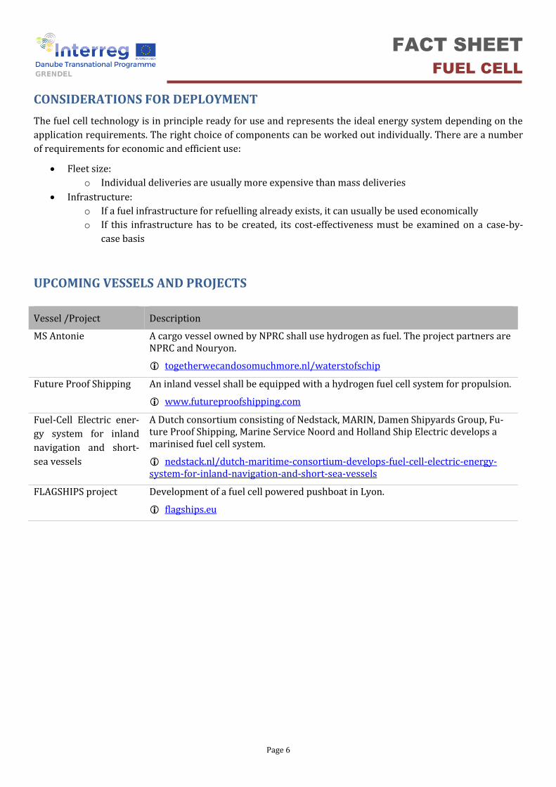
CONSIDERATIONS FOR DEPLOYMENT
The fuel cell technology is in principle ready for use and represents the ideal energy system depending on the
application requirements. The right choice of components can be worked out individually. There are a number
of requirements for economic and efficient use:
• Fleet size:
o Individual deliveries are usually more expensive than mass deliveries
• Infrastructure:
o If a fuel infrastructure for refuelling already exists, it can usually be used economically
o If this infrastructure has to be created, its cost-effectiveness must be examined on a case-by-
case basis
UPCOMING VESSELS AND PROJECTS
Vessel /Project Description
MS Antonie A cargo vessel owned by NPRC shall use hydrogen as fuel. The project partners are NPRC and Nouryon.
togetherwecandosomuchmore.nl/waterstofschip
Future Proof Shipping An inland vessel shall be equipped with a hydrogen fuel cell system for propulsion.
www.futureproofshipping.com
Fuel-Cell Electric ener-
gy system for inland
navigation and short-
sea vessels
A Dutch consortium consisting of Nedstack, MARIN, Damen Shipyards Group, Fu-ture Proof Shipping, Marine Service Noord and Holland Ship Electric develops a marinised fuel cell system.
nedstack.nl/dutch-maritime-consortium-develops-fuel-cell-electric-energy-system-for-inland-navigation-and-short-sea-vessels
FLAGSHIPS project Development of a fuel cell powered pushboat in Lyon.
flagships.eu

FACT SHEET
FUEL CELL
Page 7
DEPLOYMENT EXAMPLES
MS INNOGY Operator: Weisse Flotte Baldeney-GmbH Location: Germany, Baldeneysee, Ruhr, Rhein-Herne-Kanal Construction year: 2006 Modification: 2017 www.baldeneysee.com
Vessel type: excursion boat ENI: 04804940 Vessel size: 29 m × 4.9 m (L × W), Draught: 0.60 m Propulsion: electric motor 80 kW, reserve diesel engine 182 kW Fuell cell: 35 kW HT-PEM
Bunker capacity (Methanol): 330 liter Battery capacity: 2 × 60 kWh
FCS ALSTERWASSER Operator: ATG Alster-Touristik GmbH Location: Germany, Hamburg, Alster Construction year: 2008 Decommissioned : 2014 www.alstertouristik.de www.proton-motor.de
Vessel type: excursion boat – decommissioned Vessel size: 25.6 × 5.2 m (L × W), Draught (max): 1.33 m Propulsion: electric motor 100 kW Fuel cell : 2 × 48 kW LT-PEM
Bunker capacity (Hydrogen): 178 liter, tank pressure 350 bar Battery capacity: 7 × 29 kWh
NEMO H2 Operator: Rederij Lovers Location: Netherlands, Am-sterdam(canals) Construction year: 2009 In Operation: 2011 www.lovers.nl
Vessel type: excursion boat ENI: 02333096 Vessel size: 22 × 4.25 m (L × W), Draught (max): 1 m Propulsion: electric azimuth thruster 75 kW, electric bow thruster 11 kW, Fuel cell: 69 kW PEM
Bunker capacity (Hydrogen): 1200 liter, 24 kg, tank pressure 350 bar Battery capacity : 30-50 kW
Contact
For further information or suggestions how to improve this fact sheet please do not hesitate to contact:
DST – Development Centre for Ship Technology and Transport Systems Oststraße 77 47057 Duisburg, Germany
Phone: +49 203 99369 29 Fax: +49 203 99369 70 E-Mail: [email protected] Web: www.dst-org.de
Copyright: vlootschouw.nl
Fotocredit: EnergieAgentur.NRW, eventfotograf.in
Copyright: www.hzwei.info