fuel development status for fast reactor in china and
TRANSCRIPT
CEFR
Fuel development status for fast
reactor in China and irradiation
test plan on CEFR
Chen Huang*, Baoyu Xu, Xian Xu, Peisheng Zhang, Bangyue Yin
*Fast Reactor Research Center
Email: [email protected]
China Institute of Atomic Energy (CIAE)

CEFR
Contents
Irradiation technologies progressed Irradiation condition of CEFR Irradiation facilities designed
Irradiation plan on CEFR Irradiation plan Two Irradiation tests
Summary
Introduction Fuel development status for fast reactor MOX fuel Metallic fuel

CEFR
Contents
Irradiation technologies progressed Irradiation condition of CEFR Irradiation facilities designed
Irradiation plan on CEFR Irradiation plan Two Irradiation tests
Summary
Introduction Fuel development status for fast reactor MOX fuel Metallic fuel

CEFR
Introduction
Energy structure in China
Power generation in 2000
71.5%
2.8%
0.3%
24.8%
0.6%
Coal
Oil
Gas
Hydro
Nuclear
Power generation in
2050
55.6
4.4
5.6
14.4
13.3
6.7
Coal
Oil
Gas
Hydro
Nuclear
Other
Power generation in 2000 Power generation in 2050
55.6
13.3
71.5
0.6

CEFR
Thermal reactor Fast reactor
Fusion reactor
Fuel
China Experimental Fast Reactor (CEFR)
Critical in 2010 Operation at beginning of 2013
Irradiation technologies
Irradiation plan
Three steps for nuclear energy development

CEFR
Contents
Irradiation technologies progressed Irradiation condition of CEFR Irradiation facilities designed
Irradiation plan on CEFR Irradiation plan Two Irradiation tests
Summary
Introduction Fuel development status for fast reactor MOX fuel Metallic fuel

CEFR
Fuel development for fast reactor
● Under going ○ Application
UO2
2020 2030 2040 2050 2010 2000
MOX
MOX UPuZr
Operation
Operation
Operation
Operation
R&D Pilot Operation
Design &
Construction
● CEFR ○ CDFR
● PWR fuel reprocessing pilot
○ Industrial reprocessing plant
● MOX lab. 0.5 t/a
○ MOX Plant
○ UPuZr development

CEFR
U-Pu system for fuel cycle

CEFR
MOX fuel development
In 80’s: pre-research on MOX fuel pellets fabrication process and spent fuel
reprocessing.
Some MOX fuel pellet samples were obtained
in the laboratory.
In 90’s: the project "pre-research on feasibility of MOX fuel used in LWR".
Mechanical mixing method was determined as the main manufacturing process.
Technical specifications of MOX fuel pellet and fuel pin were primarily formulated.
From 2001 to now:
Experimental scale manufacture line of MOX fuel pellet was primarily built up.
A small laboratory for MOX fuel pellet simulation production was set up in CIAE.
Designing of MOX fuel assembly for CEFR, as well as the primary performance
analysis were carried out.

CEFR
area :1400 m, output: 500 kgHM/a
Experimental scale fabrication line of MOX fuel
2

CEFR
Flow sheet of MOX fuel pellet fabrication
UO2 PuO2
Mixing, blending
Milling
Pre-compaction
Crushing, granulation
Compaction
Sintering
Pellet inspection
Delivery check

CEFR
CEFR-MOX fuel subassembly design
Characteristics UO2 fuel MOX fuel
Assembly Length, mm 2590 2590
Pin number/SA 61 61
Wrapper size (width across flats) 59 59
Wrapper material 316(Ti)SS 316(Ti)SS
Fuel pin Length, mm 1350 1350
Cladding outer diameter, mm
Cladding thickness, mm
6.0
0.3
6.0
0.4
Cladding material CHS-68 316(Ti)SS
Fuel pellet Outer diameter, mm 5.2 5.05
Inner diameter, mm 1.6 1.6
Pu /(U+Pu), % / 25
O/M 2.000~2.015 1.96~1.99
Intrinsic density,% 95 95

CEFR
100 100
Core center
Upper blanket
Spring wire,
distance 100mm
Fuel lower blanket Pentium
Cladding
Wire
Plug CW 316(Ti) SS

CEFR
Metallic fuel development
In 90’s: research work on depleted uranium U-10Zr alloy.
Some testing devices were established, processing parameters were modified.
Some samples were fabricated.
Microstructures were observed, and physical properties were determined.
Heat treatment processing and phase transformation were studied.
In recent years, metallic fuel research work re-started.
Primary design on the metallic fuel assembly and core were finished.
Strategy of metallic fuel development in China, including production process and
re-processing was determined.
Isothermal section at different temperatures and vertical cross-section of different
compositions of U-Pu-Zr ternary alloy were calculated in order to give a
thermodynamic optimization of U-Pu-Am-Np-Zr phase diagram.
CEFR
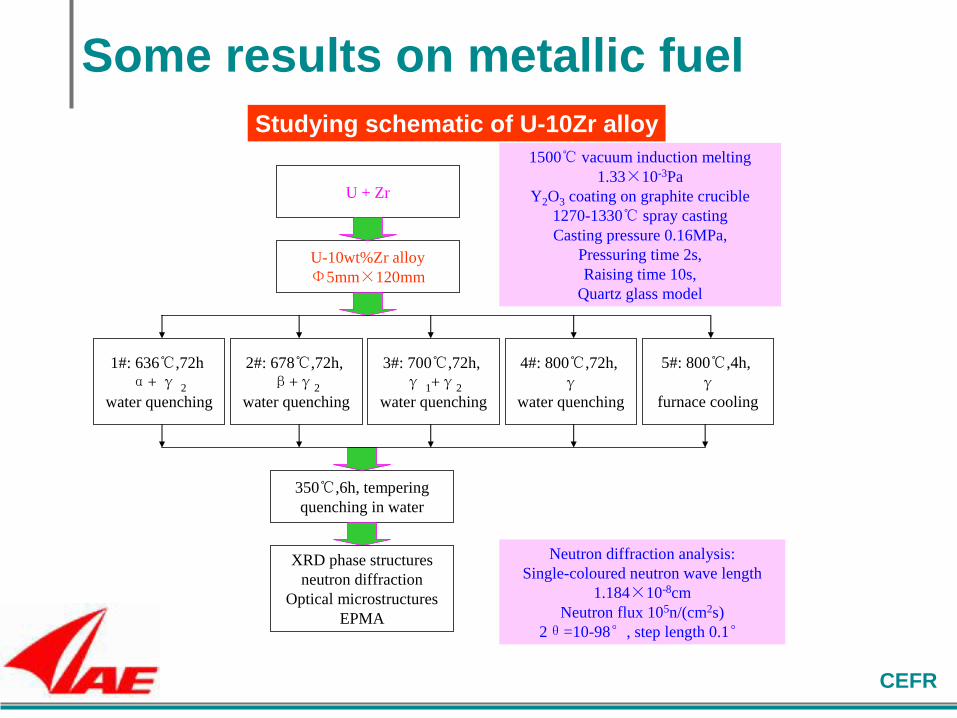
Some results on metallic fuel
U + Zr
U-10wt%Zr alloy
Φ5mm×120mm
1#: 636℃,72h
α+ γ 2
water quenching
1500℃ vacuum induction melting
1.33×10⁻³Pa
Y2O3 coating on graphite crucible
1270-1330℃ spray casting
Casting pressure 0.16MPa,
Pressuring time 2s,
Raising time 10s,
Quartz glass model
3#: 700℃,72h,
γ 1+γ2
water quenching
4#: 800℃,72h,
γwater quenching
350℃,6h, tempering
quenching in water
2#: 678℃,72h,
β+γ2
water quenching
XRD phase structures
neutron diffraction
Optical microstructures
EPMA
Neutron diffraction analysis:
Single-coloured neutron wave length
1.184×10⁻⁸cm
Neutron flux 105n/(cm2s)
2θ=10-98°, step length 0.1°
Studying schematic of U-10Zr alloy
5#: 800℃,4h,
γfurnace cooling

CEFR
Metallic fuel development roadmap
Contents 2010
2011
2012
2013
2014
2015
2016
2017
2018
2019
2020
2021
2022
2023
2024
2025
2026
2027
2028
2029
2030
2031
2032
U-Zr
U-Pu-Zr
Dry re-processing
CEFR MOX operation
2030, U-Pu-Zr irradiation test 2020, U-Zr irradiation test

CEFR
Contents
Irradiation technologies progressed Irradiation condition of CEFR Irradiation facilities designed
Irradiation plan on CEFR Irradiation plan Two Irradiation tests
Summary
Introduction Fuel development status for fast reactor MOX fuel Metallic fuel

CEFR
Main parameters (Reactor core)
Reactor Core
Item value
Normal power 65 MW
Fuel UO2(64.4%), MOX later
Max. neutron flux
E < 0.1MeV, 3.2×1015cm-2s-1
E > 0.1MeV, 2.5×1015cm-2s-1
Max./Ave. burnup
60.0/44.5 MWd/kg
Core
Height/diameter
450/600mm
UO2 mass 428kg
Max linear power
43 kW/m
Refuel period 80 d

CEFR
Fuel subassemblies
parameter value
Number of pins/SA 61
SA wrapper size 59×1.2 mm
Pin clad size Φ6.0×0.3 mm
Length of fuel zone 450 mm
Length of upper Blanket 100 mm
Length of lower Blanket 250 mm
Pentium length 450 mm
Pin length 1350 mm
SA length 2592 mm
Fuel mass/U mass 5.30/4.66 kg
Blanket material mass 4.5 kg
SA mass 29 kg

CEFR
Subassembly characteristics in operation
F_ I to F_IV refers to the four types of fuel subassemblies.
Parameter
Burn-up (%)
Max. Neutron
flux(1022cm-2)
Max. linear
power (KW/m)
Time in core
(eff. days)
Max. damage of
cladding (dpa)
F_I F_II F_III F_IV SH RE
6.2 5.8 5.4 6.3 6.5 12.9
0.65 0.61 0.55 0.62 0.63 0.63
40.1 37.0 34.2 30.5 19.4 6.5
240 240 240 240 240 400
27.0 25.0 23.0 26.0 25.0 22.0

CEFR
Core loading flexibility
1st inner ring of reflector SAs can be replaced by fuel SAs.
1st to 3nd ring of reflector SAs can be replaced by blanket SAs.
It is possible to install experimental SAs in the area of fuel SAs and reflector SAs.

CEFR
PIE technologies in CIAE
None-destructive exam. hot cell in CEFR
Semi-hot cell in CIAE
Destructive exam. hot cell: current and planed in CIAE

CEFR
Non-destructive examination hot cell
• Visual inspection
• Dimensional measurement of SA and pin
• X-ray radiography
• Gamma scanning
• Eddy current exam.

CEFR
Semi-hot cell

CEFR
Destructive examination hot cell
• Visual inspection and store for short fuel pin
• Dimension measurement
• Sample cutting
• Punch test
• Tensile test
• Metallography
• Density measurement

CEFR
New destructive examination hot cell (planned stage)
Two stories with the total building area of about 10800 m
Fuel test Materials
test
SA
re-assembly
2

CEFR
Irradiation facilities developed
for structural materials for fuel pin for fuel bundles
Off-line irradiation facility
temperature
neutron flux
On-line irradiation facility

CEFR
Irradiation facility for structural materials
Wrapper
Outer Container
Inner container
Samples

CEFR
Irradiation facility for single pin
Wrapper
Separation tube
Test pin
Capsule

CEFR
Item Value
Capsule Length, mm 453
Outer diameter, mm 7.2
Thickness, mm 0.4
Sodium quantity, g ~1.3
Tested pin Length, mm 392
Fuel stack height, mm 180
Outer diameter, mm 6
Cladding thickness, mm 0.4
Core center
Upper Connect Tested pin Capsule Lower connect

CEFR
Irradiation facility for fuel bundles
Wrapper
Outer tube
Fuel bundle
Inner tube

CEFR
Contents
Irradiation technologies progressed Irradiation condition of CEFR Irradiation facilities designed
Irradiation plan on CEFR Irradiation plan Two Irradiation tests
Summary
Introduction Fuel development status for fast reactor MOX fuel Metallic fuel

CEFR
Irradiation test plan on CEFR
2011 2012 2013 2014 2015 2016
Power test, power
generation
316(Ti)SS
Np added fuel
MOX fuel
15-15TiSS
FMS steel
Focus on domestic fuel irradiation.
Materials irradiation also considered.
Other irradiation tests.

CEFR
Irradiation test of 316(Ti)SS
• Material: CW316(Ti)SS
• Irradiation temperature: 450, 500, 600C
• Irradiation position: neutron source assembly
• Monitoring: temperature, neutron fluent
Double axis
creep test Swelling
test
Microstructure
Tensile,
creep
test
Cladding
tube
tensile test

CEFR
Irradiation test facility

CEFR

CEFR
Irradiation test for Np added fuel

CEFR
EU-China cooperation on irradiation test
• Access to Large Infrastructures in China and Europe (Under the Eu-7
programme)
• Cooperation partners: CEFR and SCK-CEN (Belgian Nuclear Research
Centre )
• Main research works:
Definition of access conditions to the participating infrastructures in
the EU and China.
Cooperation designing on irradiation facility
Structural materials irradiation in BR-2
Same materials irradiation in CEFR
• Irradiation temperature: ND
• Irradiation damage: ~8dpa
• Monitoring: on-line in BR-2, off-line on CEFR

CEFR
Contents
Irradiation technologies progressed Irradiation condition of CEFR Irradiation facilities designed
Irradiation plan on CEFR Irradiation plan Two Irradiation tests
Summary
Introduction Fuel development status for fast reactor MOX fuel Metallic fuel

CEFR
Summaries
The development trend of fast reactor fuel in China is similar as that
world wide. MOX fuel is the basic fuel type, and metallic fuel as well as
other advanced fuels are also considered.
The irradiation technologies of CEFR has being developed.
The primary irradiation plan has been determined, which emphasis is on
domestic MOX fuel.
CEFR will be the platforms for R & D international cooperation on
materials development for nuclear usage.

CEFR
CEFR
The platform for R&D international
cooperation on fast reactor
Thank you!

CEFR
Development schedule for cladding materials used in fast reactor
316(Ti)SS
2010 2011 2012 2013 2014 2015 2016
316(Ti)SS Mod. Or15-15TiSS
ODS
FMS
Supplemental tests
Irradiation test prep. Irradiation test PIE Commercial
application
Performance out-of-pile Irradiation test PIE
Performance out-of-pile
Irradiation test PIE Research for
commercial use
Performance out-of-pile

CEFR