fuel tank internal wiring installation quality...fuel tank inspections - what to look for fqis and...
TRANSCRIPT
Fuel Tank Internal WiringInstallation Quality
Larry Reising, ANM-140SFAA Seattle ACO425-227-2683
Purpose of Presentation■ Show results of in-tank wiring inspections on
new transport aircraft■ Overview of the tank inspection process■ Convey “lesson learned”
Background■ In 1998, the Seattle ACO Propulsion Branch
(ANM-140S) requested tank inspections on atransport airplane for compliance substantiationand continued airworthiness
■ Significant problems found, resulted in a CMR andan AD
■ Ever since, ANM-140S has periodically performedin-tank wire inspections on different airplanes
■ Examples of in-tank wiring are shown herein■ Limited discussion on other areas to inspect is
provided
Importance of In-Tank Wire Installation Quality
■ Good in-tank wire installation quality is one meansto help preclude ignition sources
■ Good wire installations mean less FQIS problems,leading to less tank entries, leading to reduced riskof tank contamination or component damage
■ Less in-tank FQIS wire problems also meanshappy operators
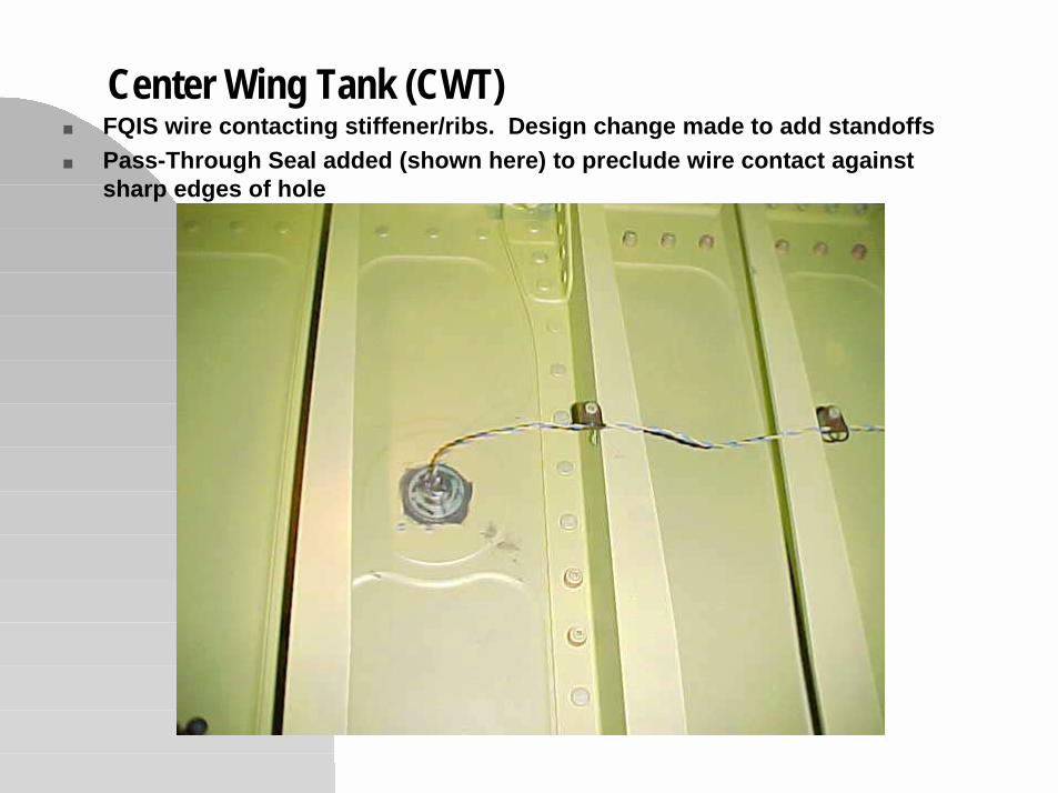
Center Wing Tank (CWT)■ FQIS wire contacting stiffener/ribs. Design change made to add standoffs■ Pass-Through Seal added (shown here) to preclude wire contact against
sharp edges of hole

CWT■ Drip Loop Contacting Floor

CWT■ Anything Wrong Here?

CWT■ Closer look, different angle reveals problems with wire
bundle contacting bracket edge.
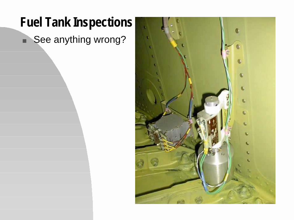
Fuel Tank Inspections■ See anything wrong?
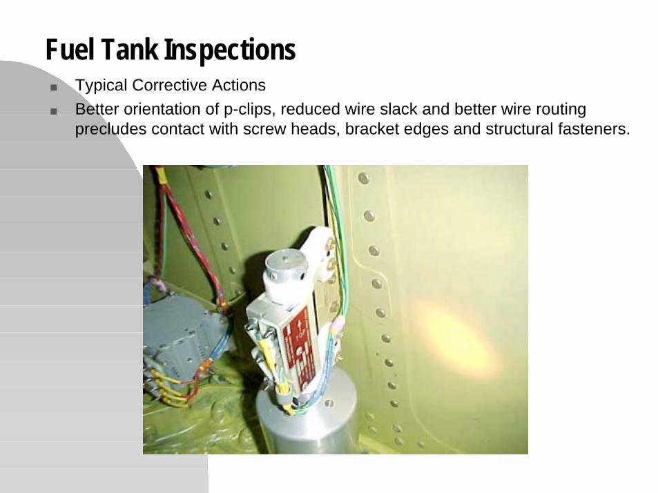
Fuel Tank Inspections■ Typical Corrective Actions■ Better orientation of p-clips, reduced wire slack and better wire routing
precludes contact with screw heads, bracket edges and structural fasteners.
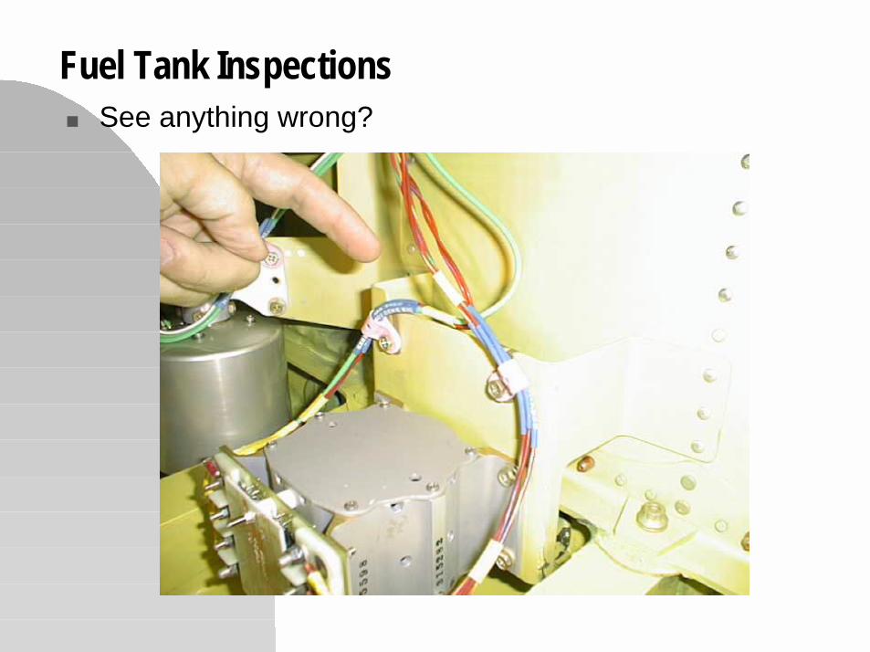
Fuel Tank Inspections■ See anything wrong?
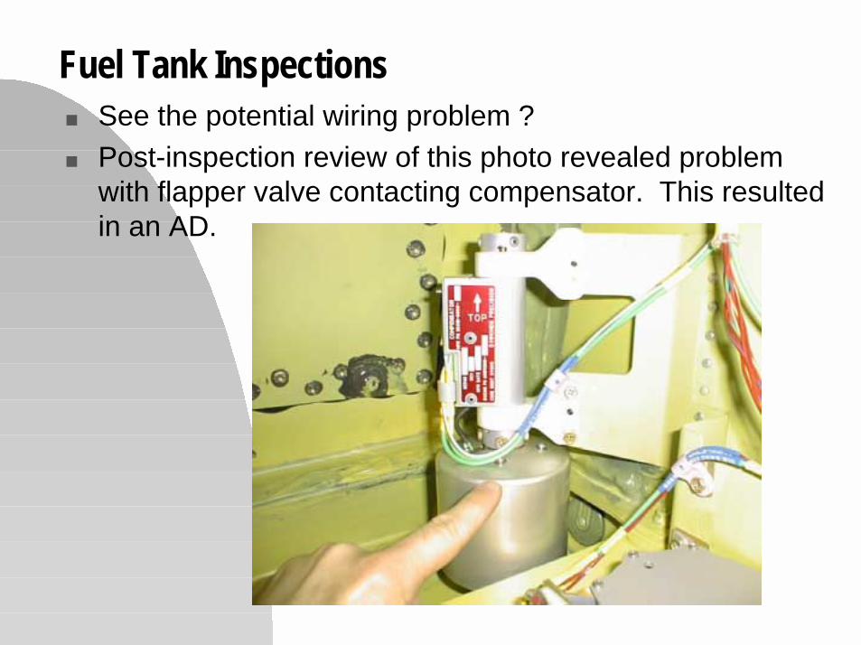
Fuel Tank Inspections■ See the potential wiring problem ?■ Post-inspection review of this photo revealed problem
with flapper valve contacting compensator. This resultedin an AD.
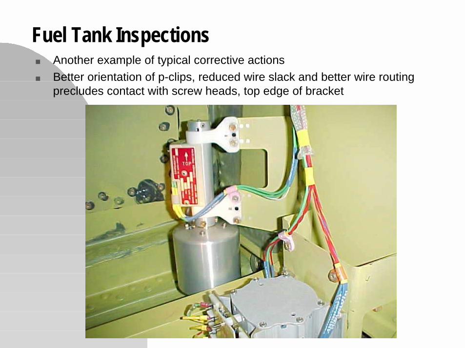
Fuel Tank Inspections■ Another example of typical corrective actions■ Better orientation of p-clips, reduced wire slack and better wire routing
precludes contact with screw heads, top edge of bracket
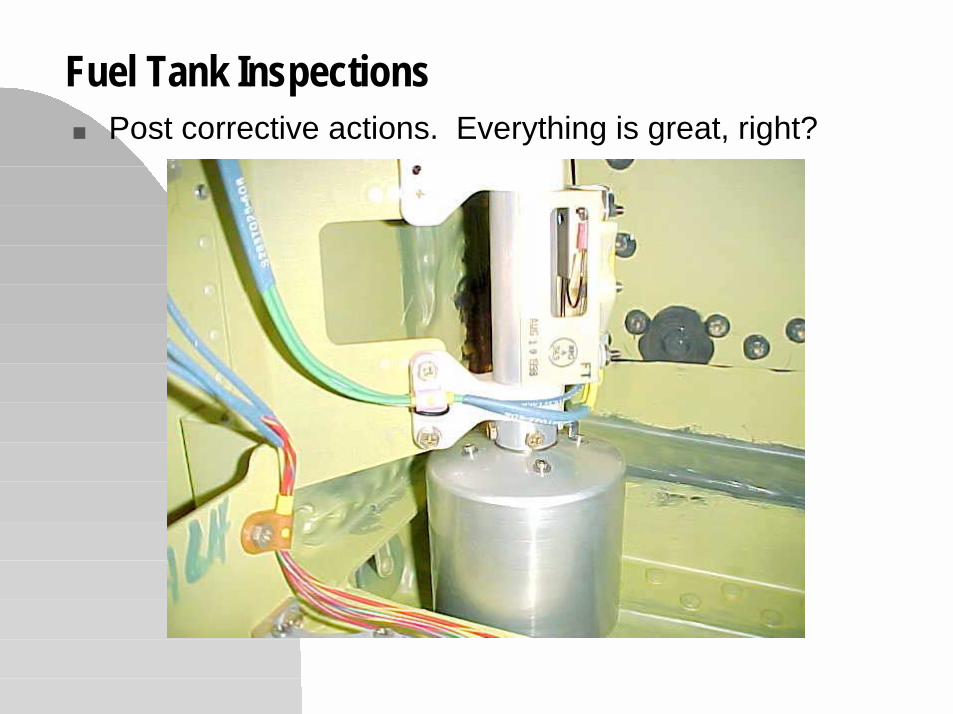
Fuel Tank Inspections■ Post corrective actions. Everything is great, right?
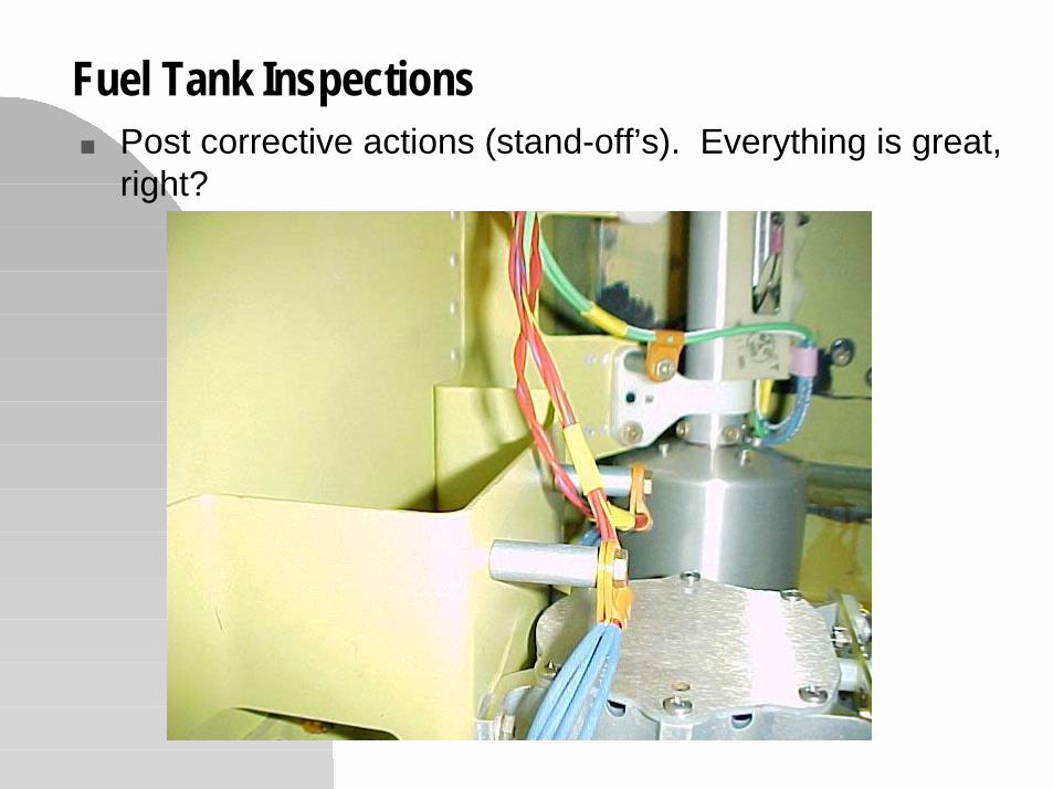
Fuel Tank Inspections■ Post corrective actions (stand-off’s). Everything is great,
right?

Conducting In-Tank Wire Inspections - Preparation(This was written for ACO’s. Others can benefit)
■ ACO’s should work with their MIDO, and request that theyinitiate, and conduct the inspections with ACO support
■ Make sure it is clear that you will only enter the tank afterQuality Assurance has accepted it, and it is ready to close
■ Attempt to get confined space and dry fuel cell entry training.It is not actually required, however, it is useful and contributesto safety. (For Boeing, these are courses 6C66193 and6C64314)
■ Assure that responsible DER’s, design engineer’s and QualityAssurance personnel will be available. Ask them to havedrawings available, and prepare a short familiarizationbriefing.
■ Sign out camera (preferably digital)
Conducting In-Tank Wire Inspections - The Day of
■ Bring camera■ Wear sneakers and “very casual” clothes. Don’t wear jewelry.■ Typically, you will be issued tank-entry equipment. Ask for guidance
in using all of this.■ Regarding the digital camera - verify it’s OK to use in the dry fuel
cell. DO NOT USE A CAMERA IN A WET TANK (a tank that hashad fuel in it is considered wet.)
■ When entering or exiting tanks, watch how other’s do it. Relax, takeyour time. Let others assist you.
■ When taking pictures, have someone shine a flashlight on thecomponent to help the camera focus. If you keep getting over-exposures, partially cover the flash with your finger. (Sony Mavica’swork great, but take a while to focus)
■ Sealant vapors can be strong. Take breaks as needed.

Fuel Tank Inspections■ ANM-130S Engineer Mr. Steve Oshiro Demonstrates
Correct Tank Entry Protocol
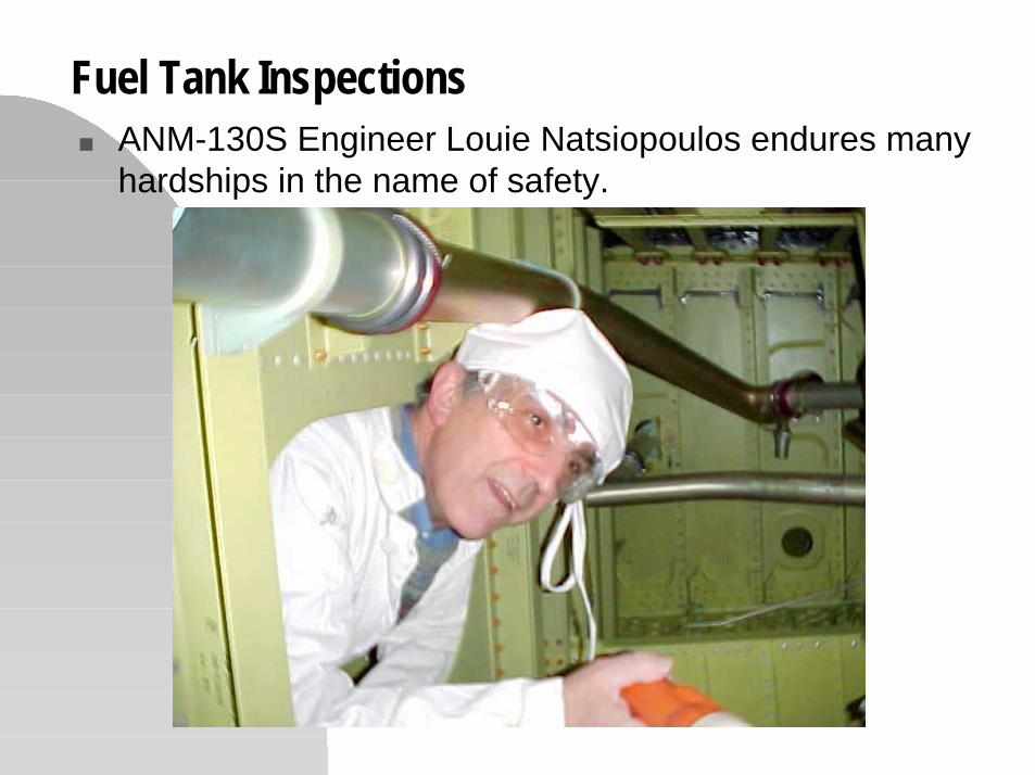
Fuel Tank Inspections■ ANM-130S Engineer Louie Natsiopoulos endures many
hardships in the name of safety.
Fuel Tank Inspections - What to look for■ FQIS and other in-tank wiring problems discussed herein■ Missing, or loose sealant■ Debris■ Damage to components■ Missing components, such as fuel pump inlet screens■ Missing or poorly installed bonding wire on tank plumbing■ Inappropriate faying surfaces (Consider spot-checking brackets for
appropriate faying surfaces. Note bracket location, check drawingrequirements later).
■ If you are inexperienced in what to look for, consider going in withsomeone more experienced in fuel tank inspections
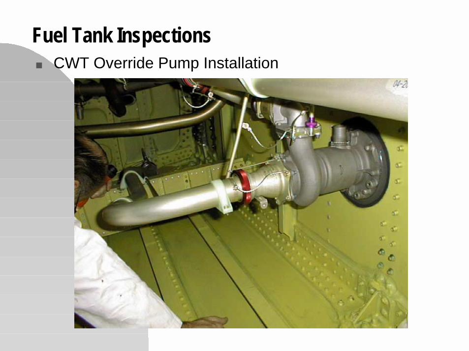
Fuel Tank Inspections■ CWT Override Pump Installation
Fuel Tank Inspections - Documentation■ Do it right away, while still on site■ Download digital pictures and use a laptop■ Nominate a scribe to document results■ Discuss each photo. Get other’s input■ Go back and re-inspect if you disagree on a problem■ Typically, QA & engineers will want to go back and discuss
appropriate fixes■ Often, you are presented with the rejection tags or similar
paperwork. If not, request that it be sent to you (so you can verifyit was correctly documented).
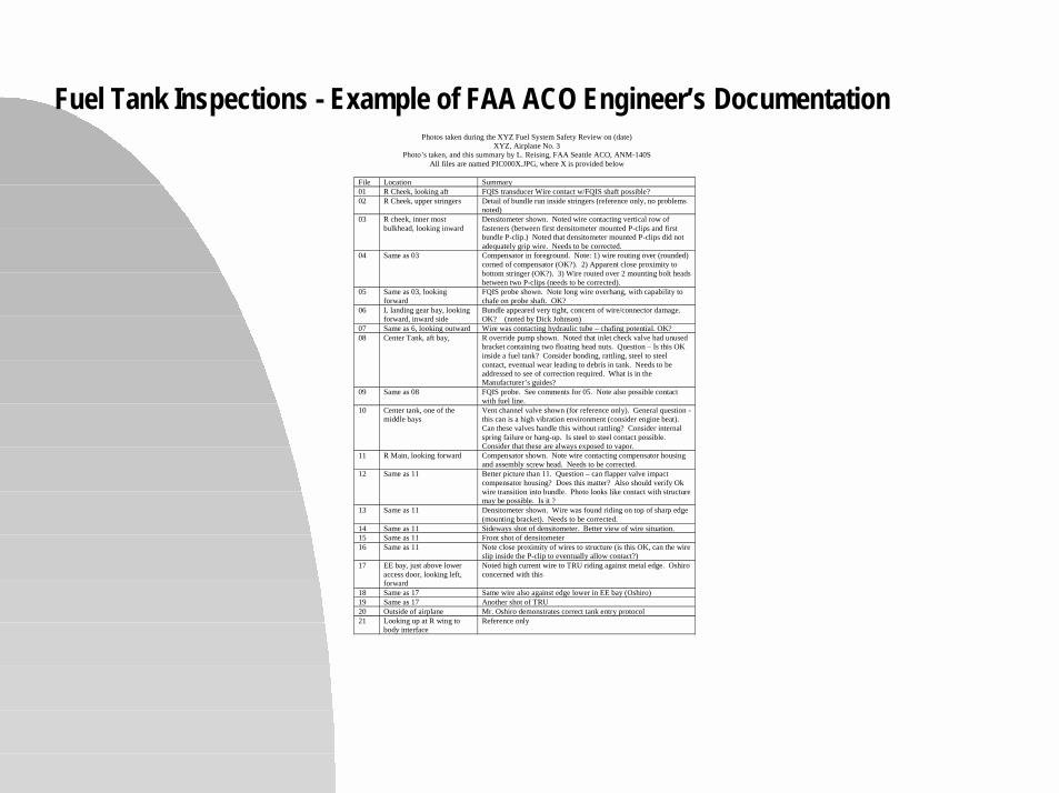
Fuel Tank Inspections - Example of FAA ACO Engineer’s DocumentationPhotos taken during the XYZ Fuel System Safety Review on (date)
XYZ, Airplane No. 3Photo’s taken, and this summary by L. Reising, FAA Seattle ACO, ANM-140S
All files are named PIC000X.JPG, where X is provided below
File Location Summary01 R Cheek, looking aft FQIS transducer Wire contact w/FQIS shaft possible?02 R Cheek, upper stringers Detail of bundle run inside stringers (reference only, no problems
noted)03 R cheek, inner most
bulkhead, looking inwardDensitometer shown. Noted wire contacting vertical row offasteners (between first densitometer mounted P-clips and firstbundle P-clip.) Noted that densitometer mounted P-clips did notadequately grip wire. Needs to be corrected.
04 Same as 03 Compensator in foreground. Note: 1) wire routing over (rounded)corned of compensator (OK?). 2) Apparent close proximity tobottom stringer (OK?). 3) Wire routed over 2 mounting bolt headsbetween two P-clips (needs to be corrected).
05 Same as 03, lookingforward
FQIS probe shown. Note long wire overhang, with capability tochafe on probe shaft. OK?
06 L landing gear bay, lookingforward, inward side
Bundle appeared very tight, concern of wire/connector damage.OK? (noted by Dick Johnson)
07 Same as 6, looking outward Wire was contacting hydraulic tube – chafing potential. OK?08 Center Tank, aft bay, R override pump shown. Noted that inlet check valve had unused
bracket containing two floating head nuts. Question – Is this OKinside a fuel tank? Consider bonding, rattling, steel to steelcontact, eventual wear leading to debris in tank. Needs to beaddressed to see of correction required. What is in theManufacturer’s guides?
09 Same as 08 FQIS probe. See comments for 05. Note also possible contactwith fuel line.
10 Center tank, one of themiddle bays
Vent channel valve shown (for reference only). General question -this can is a high vibration environment (consider engine beat).Can these valves handle this without rattling? Consider internalspring failure or hang-up. Is steel to steel contact possible.Consider that these are always exposed to vapor.
11 R Main, looking forward Compensator shown. Note wire contacting compensator housingand assembly screw head. Needs to be corrected.
12 Same as 11 Better picture than 11. Question – can flapper valve impactcompensator housing? Does this matter? Also should verify Okwire transition into bundle. Photo looks like contact with structuremay be possible. Is it ?
13 Same as 11 Densitometer shown. Wire was found riding on top of sharp edge(mounting bracket). Needs to be corrected.
14 Same as 11 Sideways shot of densitometer. Better view of wire situation.15 Same as 11 Front shot of densitometer16 Same as 11 Note close proximity of wires to structure (is this OK, can the wire
slip inside the P-clip to eventually allow contact?)17 EE bay, just above lower
access door, looking left,forward
Noted high current wire to TRU riding against metal edge. Oshiroconcerned with this
18 Same as 17 Same wire also against edge lower in EE bay (Oshiro)19 Same as 17 Another shot of TRU20 Outside of airplane Mr. Oshiro demonstrates correct tank entry protocol21 Looking up at R wing to
body interfaceReference only

Fuel Tank Inspections - Corrective Actions■ Typically involves both engineering changes and enhanced QA
activity
■ Recognize that factories can have relatively high turn-over in bothassembly personnel and in QA inspectors. For this reason, thebetter fix is a better design (i.e. one that does not require extremeattention to detail during assembly and inspection)
■ Clarification notes in drawings are rarely effective in the long run
■ If you find an unacceptable condition in the factory, be sure toassess the need for corrective actions for in-service airplanes.
In-Tank Wire Inspections - Long Term Effectiveness
■ Experience is that in-tank wire installation quality improvessignificantly after FAA inspection, but drops off after time
■ Consider asking the manufacturer to set up a quality team toassure that lessons learned get transferred across airplanemodels, and that the in-tank wire quality is maintained overtime
■ For FAA ACO personnel - consider working with MIDO to setup periodic FAA inspections to verify the results of themanufacturer’s quality team(s)